experimental investigation of the velocity distribution near the swirl...
TRANSCRIPT

18th International Symposium on the Application of Laser and Imaging Techniques to Fluid Mechanics・LISBON | PORTUGAL ・JULY 4 – 7, 2016
Experimental Investigation of the Velocity Distribution near the Swirl Generator of a Uniflow Cyclone for Performance Data Prediction
M. Pillei1,2,*, R. Goller1, T. Kofler1, A. Wierschem2, M. Kraxner1 1: Dept. of Environmental, Process & Energy Engineering, MCI - The Entrepreneurial School, Austria
2: Dept. of Fluid Mechanics, Friedrich-Alexander-Universität Erlangen-Nürnberg (FAU), Germany * Correspondent author: [email protected]
Keywords: 2D/3C-PIV, swirl flow, gas-solid-separation, uniflow cyclone
ABSTRACT
Uniflow cyclones are used for the separation of a dispersed solid phase from a continuous fluid phase. This separators have gas and particles passing through them in only one direction. In uniflow cyclones, particles separate due to centrifugal forces in the swirling flow, which is generated by the swirl generator, in radial direction towards the particle discharge area [1,2]. In early works the swirl generator blades and the vortex finder shape could be identified as key parameter strongly affecting the performance, by means of separation efficiency η and pressure drop Δp. [3] The aim of this work is to predict the effect of modifications in geometry on the performance of this type of gas-solid separators. For this purpose 2D/3C-PIV measurements have been carried out to evaluate the flow field distribution as a function of the outer vane angle α and the core ratio Dk/Dz of the swirl generator in an uniflow cyclone. We present a study on the fluid flow pattern in the swirl generator zone to predict the separation efficiency of a uniflow cyclone at moderate conditions. [4] Therefore an evaluation of the velocity distribution is carried out to identify the velocity peak of the circumferential component with the strongest impact. Moreover the peak position in the evaluated cross section is used to derive a correlation factor Γ. This factor is then compared with the results from the performed dedusting tests.
1. Introduction Uniflow cyclones used for separation have gas and particles passing through them in only one direction. This separator class is used especially in environments where easy retrofitting is needed and problems with space limitations occur. Due to the fact that currently in industry there is no generally accepted layout criteria defined, further investigations are necessary. Therefore systematic experimental studies are made to investigate the influences of essential geometry parameter changes in the swirl generator design. For the investigation of the high swirling flow 2D/3C-PIV measurements are carried out to investigate the velocity field distribution over the cross section area in the uniflow cyclones separation chamber. The MCI intends to develop design fundamentals for this separator class to provide deep insight into the operation of such devices. 2. Experimental

18th International Symposium on the Application of Laser and Imaging Techniques to Fluid Mechanics・LISBON | PORTUGAL ・JULY 4 – 7, 2016
For the experimental study two similar test stands are built to ensure comparability, one for the 2D/3C-PIV measurements fluid flow evaluation and the other one for the multiphase separation tests and the gravimetric analysis. Fig. 1 describes the components for the experimental setup. The raw gas is entering the separator in positive x-direction. The seeding generator creates tracer droplets with a modal diameter of approx. 1,2 µm. The diameter Dk describes the core diameter of the swirl generator and Dz the cyclones inner diameter. The laser sheet is aligned perpendicular to the main flow direction and the source is positioned in pos. z-direction at a position of 0,35 L/Dz in downstream direction of the swirl generator. The two cameras for the stereoscopic evaluation are positioned in an angle λ of 40° each. For depth of field enhancement the cameras use scheimpflug adapters with an angle of β = 8°.
Fig. 1 Schematic experimental setup.
The velocity distribution is examined with a stereoscopic 2D/3C-PIV system to evaluate all velocity components of the fluid flow simultaneously over the cross section area. The main parameters for the measurement are listed in Tab. 1. The separation chamber consists of borosilicate glass with a low surface roughness of the pipe to reduce the optical refractions and other artifacts e.g. flow-marks or fluctuations in wall thickness.

18th International Symposium on the Application of Laser and Imaging Techniques to Fluid Mechanics・LISBON | PORTUGAL ・JULY 4 – 7, 2016
Configuration Value
Laser Type Nd:YAG Frequency 532 nm Puls distance 10 µm
Optics Aperture f1.8 Camera Setup 2D/3C
Fluid flow Re approx. 65000
Tab. 1 Parameters of the 2D/3C-PIV measurement.
The uniflow cyclones performance data (separation efficiency η, pressure drop Δp) is obtained by dedusting tests conform to ISO 5011:2014 for inlet air cleaning equipment with a solids loading of 8,3e-4 g/g. A calibrated orifice plate is used to validate the fluid flow due to DIN EN ISO 5167-1:2004-01. For validation issues the scalar values of the axial velocities are integrated over the cross section area to fulfill the measurement requirements. With respect to the ambiguous problem (diameter, reconstruction of warped images, ...) the results show a good agreement with a max. variance < 4% between PIV and the reference measurement. The reason for the deviation is caused by the strong distortion especially in the near wall region resulting in deviant vectorial results. 2. Results & Discussion Fig. 2 describes the velocity distribution of the mainly contributing velocity components in axial direction v/v0 (Fig. 3a) and in circumferential direction u/u0 (Fig. 3b) in the flow field. Moreover the plots show the results of 3 different cyclones with different outer vane angles α (30°, 45°, 60°) at Dk/Dz = 0,5, see Fig. 3.
(a) norm. axial velocity v/v0 (b) norm. circumferential velocity u/u0
Fig. 2 Velocity distribution at L/Dz = 0,35 for different outer vane angles α.

18th International Symposium on the Application of Laser and Imaging Techniques to Fluid Mechanics・LISBON | PORTUGAL ・JULY 4 – 7, 2016
Fig. 3 Schematic experimental setup.
The radius r/Rz describes the normalized position r in radial direction of the cross section with respect to the normalized inner pipe radius Rz of the separation chamber. The radius Rz is defined as Dz/2, see Fig. 1. These outer vane angles α represent characteristic values for uniflow cyclones, see [5]. The normalized values u0, v0 correspond to a dataset of 9 cyclones with an additional modification of the Dk/Dz ratio of 0,375 and 0,625.
The error bars represent the standard deviation with a confidence interval of 95% of 3 repeated measurements each. Related values are normalized to the maximum value of each corresponding velocity component (e.g. u/u0 for circumferential velocity) of the dataset. The area shown grayed out represents the central section with low tracer particle seeding concentration due to the high centrifugal forces. The area shown in Fig. 3 represents for both images the worst case of the dataset. The dashed lines represent the region with limited correlation capabilities due to reduced seeding concentrations. The fitted velocities in Fig. 3a vfitted correspond to a fitting algorithm from similar velocity distributions to fulfill the law of conservation of mass. [6]
Fig. 4 Identification of circumferential velocity peak r-pos-max, u-pos-max.
18th International Symposium on the Application of Laser and Imaging Techniques to Fluid Mechanics・LISBON | PORTUGAL ・JULY 4 – 7, 2016
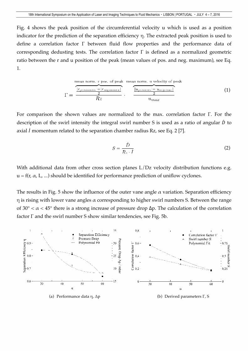
Fig. 4 shows the peak position of the circumferential velocity u which is used as a position indicator for the prediction of the separation efficiency η. The extracted peak position is used to define a correlation factor Γ between fluid flow properties and the performance data of corresponding dedusting tests. The correlation factor Γ is defined as a normalized geometric ratio between the r and u position of the peak (mean values of pos. and neg. maximum), see Eq. 1.
(1)
For comparison the shown values are normalized to the max. correlation factor Γ. For the description of the swirl intensity the integral swirl number S is used as a ratio of angular 𝐷 to axial 𝐼 momentum related to the separation chamber radius Rz, see Eq. 2 [7].
(2)
With additional data from other cross section planes L/Dz velocity distribution functions e.g. u = f(r, α, L, ...) should be identified for performance prediction of uniflow cyclones. The results in Fig. 5 show the influence of the outer vane angle α variation. Separation efficiency η is rising with lower vane angles α corresponding to higher swirl numbers S. Between the range of 30° < α < 45° there is a strong increase of pressure drop Δp. The calculation of the correlation factor Γ and the swirl number S show similar tendencies, see Fig. 5b.
(a) Performance data η, Δp (b) Derived parameters Γ, S

18th International Symposium on the Application of Laser and Imaging Techniques to Fluid Mechanics・LISBON | PORTUGAL ・JULY 4 – 7, 2016
Fig. 5 Comparison of performance data and derived parameters for Dk/Dz = 0,5.
3. Conclusions The separation efficiency η is rising with lower vane angles α corresponding to higher swirl numbers S. The peak position of the tangential velocity is used as a position indicator for the prediction of the separation efficiency η. The calculation of the correlation factor Γ and the swirl number S show similar tendencies. The peak of the circumferential velocity distribution is moving in radial direction which leads to a faster movement of particles towards the separation region near the vortex finder of the uniflow cyclone. 4. Outlook For the estimation of the cut size diameter of the separator also the radial component is relevant. A suitable ratio of radial to circumferential velocity in the vortex finder zone is needed for high separation efficiency and low pressure drop. Therefore the next step is the investigation of the radial component of the velocity field to get a deeper insight towards the separation fundamentals and optimized layout criteria. 5. Notation D Angular momentum PIV Particle image velocimetry DC Cyclone diameter Nd:YAG Neodymium-doped yttrium alu-
minium garnet Dk Core diameter I Axial momentum L Length r,R Radius S Swirl number u Circumferential vel. v Axial vel. α Vane Angle Γ Correlation factor Δp Pressure Drop η Separation efficiency

18th International Symposium on the Application of Laser and Imaging Techniques to Fluid Mechanics・LISBON | PORTUGAL ・JULY 4 – 7, 2016
6. References [1] Stiess M (2009) Mechanische Verfahrenstechnik. Springer, Berlin [2] Mothes H, Löffler F (1984) Bewegung und Abscheidung der Partikeln im Zyklon. Chemie
Ingenieur Technik 56(9):714-715 [3] Weng M (2002) Experimentelle und numerische Untersuchung von Gleichstrom-
zyklonen. Shaker, Aachen [4] Kraxner M (2013) Empirische Ermittlung von Auslegungskriterien für Gleichstrom-
zyklone in Multizyklonblöcken. PhD Thesis, TU München [5] Hofmann A C, Stein L E (2002) Gas Cyclones and Swirl Tubes - Principles, Design and
Operation. Springer, Berlin [6] Kraxner M, Pillei M, Muschelknautz U (2012) Stereoskopische PIV-Messung eines
Wirbelzerfalles bis 40x DRohr - Mathematische Modellierung. In: Leder A (2012) Lasermethoden in der Strömungsmesstechnik, GALA e.V., Karlsruhe
[7] Beer J M, Chigier N H (1972) Combustion Aerodynamics. Applied Science Publishers, London