experimental investigations on co -based … investigations on co 2-based transcritical rankine...
TRANSCRIPT
Experimental Investigations on CO2-Based Transcritical Rankine Cycle (CTRC) for Waste Heat Recovery of Diesel Engine
Lingfeng Shi, Gequn Shu, Hua Tian et al.
State Key Laboratory of Engines (SKLE), Tianjin University, Tianjin, China
Email: [email protected] / [email protected]

4. Summary
Outline
2. System and Method
3. Results
1. Background

3
Turbocharging
Thermoelectric generator
Power or Work
Thermodynamic Cycle: High efficiency
Well thermal match
Good feasibility
Thermodynamic Cycle
Background-Why Engine WHR?
WHR
Energy Saving

4 Backgroud-Why CTRC?
CO2 is a natural working fluid Safe: non-toxic, non-corrosive, inflammable, non-explosive
Environmentally friendly: ODP=0, GWP=1
High thermal stability: direct contact with HT exhaust gas
Supercritical CO2 has unique thermophysical properties Tcrit=31.1 ℃; Pcrit=7.38 MPa
High density, low viscosity
Small expansion ration Compact turbine, Compact HE

5 Backgroud-Why CTRC?
CTRC could achieve miniaturization
Meet the demand of mobile applications
CTRC could better recover exhaust and coolant energy
simultaneously (Applied Energy, 2016, 176:171-182. )
Even both utilization rate of 1
Utilization rate comparison between CTRC and ORC (R123)
Heat absorption capbility between CO2 and R123
CTRC
ORC
Low Utilizaiton rate of engine coolant for ORC
Engine Coolant
Exhaust Gas

6
Drawback of B-CTRC:
Low thermal efficiency
Low power output
Background-Basic CTRC
Thermal efficiency comparison between CTRC and ORCs ((Zhang et al. Appl. Eng. 88 (2011) 2740–2754))
B-CTRC Components:
Pump
Gas heater
Turbine & Generator
Condenser
B-CTRC: CTRC with Basic Configuration

7 Background-Modified CTRC
Efficient Solution: Modified Configurations
P-CTRC: CTRC with Preheated Configuration
1. Add energy input from outside: engine coolant as preheat source
2. Add energy input from inside: high temp. exhaust CO2
3. Both of 1 and 2
R-CTRC: CTRC with Regenerated Configuration
PR-CTRC: CTRC with Preheated and Regenerated Configuration
Object of study (experimental way): Compare thermodynamic performance between four CTRC configurations and find improved degree by modified CTRC

4. Summary
Outline
2. System and Method
3. Results
1. Background

Expansion Valve
PT
PTPT
T T
Diesel Engine
Gas Heater
Regenrator
PrecoolerCondenserCO2 TankFilter
CO2 Flowmeter
CO2 Pump
Damper
Refrigeration Unit
Preheater
PT PT
PT
T P
PT
PT
T
T
PT
PTT & P Sensor
T Display
P Display
ValveCooling Water
Exhaust Gas
Engine Coolant (EC)
CO2
T
EC Flowmeter1
EC Tank
EC Pump1
EC Pump2
Cooling Water Flowmeter
Cooling Jacket
1 2 3
456
7
9
c,1 c,2
g,1
ec,1
ec,2
ec,3
ec,4
c,3
g,2
g,0 PT
Valve1 Valve2
Valve3 Valve4
EC Flowmeter2
Cold EC Supplement
Valve5
Valve6
8T P
PT
PT
9 System Layout
Main design parameters:
Power output:4.5kW Maximum pressure : 11MPa Maximum temperature : 230℃
Diesel engine
system
Engine coolant
system
CTRC system

10 System Photos CTRC system
Control, Record and Alarm
Pump Gas heater
The other HEs Expansion Valve/ Turbine

Expansion Valve
PT
PTPT
T T
Diesel Engine
Gas Heater
Regenrator
PrecoolerCondenserCO2 TankFilter
CO2 Flowmeter
CO2 Pump
Damper
Refrigeration Unit
Preheater
PT PT
PT
T P
PT
PT
T
T
PT
PTT & P Sensor
T Display
P Display
ValveCooling Water
Exhaust Gas
Engine Coolant (EC)
CO2
T
EC Flowmeter1
EC Tank
EC Pump1
EC Pump2
Cooling Water Flowmeter
Cooling Jacket
1 2 3
456
7
9
c,1 c,2
g,1
ec,1
ec,2
ec,3
ec,4
c,3
g,2
g,0 PT
Valve1 Valve2
Valve3 Valve4
EC Flowmeter2
Cold EC Supplement
Valve5
Valve6
8T P
PT
PT
11 Four CTRC Switch
Control EC Pump1:
On: With Preheating
off: Without Preheating
Control Valve1-4:
On: With IHX
Off: Without IHX
B-CTRC R-CTRC P-CTRC PR-CTRC
EC Pump1 Off Off On On
Valve1-4 Off On Off On
Four CTRC configurations can be tested in this bench:
Expansion Valve
PT
PTPT
T T
Diesel Engine
Gas Heater
Regenrator
PrecoolerCondenserCO2 TankFilter
CO2 Flowmeter
CO2 Pump
Damper
Refrigeration Unit
Preheater
PT PT
PT
T P
PT
PT
T
T
PT
PTT & P Sensor
T Display
P Display
ValveCooling Water
Exhaust Gas
Engine Coolant (EC)
CO2
T
EC Flowmeter1
EC Tank
EC Pump1
EC Pump2
Cooling Water Flowmeter
Cooling Jacket
1 2 3
456
7
9
c,1 c,2
g,1
ec,1
ec,2
ec,3
ec,4
c,3
g,2
g,0 PT
Valve1 Valve2
Valve3 Valve4
EC Flowmeter2
Cold EC Supplement
Valve5
Valve6
8T P
PT
PT
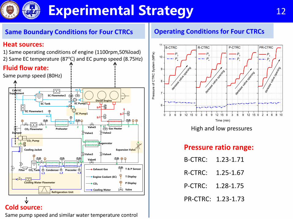
12 Experimental Strategy
Heat sources: 1) Same operating conditions of engine (1100rpm,50%load) 2) Same EC temperature (87℃) and EC pump speed (8.75Hz)
Fluid flow rate: Same pump speed (80Hz)
Cold source: Same pump speed and similar water temperature control
Same Boundary Conditions for Four CTRCs Operating Conditions for Four CTRCs
Pressure ratio range:
B-CTRC: 1.23-1.71
R-CTRC: 1.25-1.67
P-CTRC: 1.28-1.75
PR-CTRC: 1.23-1.73
High and low pressures

4. Summary
Outline
2. System and Method
3. Results
1. Background
Energy Input Net Power Output (estimation) Cooling load
{

14 Energy Input
Versus the B-CTRC, increase of Qa,total: R-CTRC: 18% P-CTRC:34% PR-CTRC :57% .
PR-CTRC(199) > P-CTRC > R-CTRC > B-CTRC (99)
Maximum Temp. of CO2 Heat Absorption Quantity (Qa,total)
Inlet Temp. of Gas Heater
Inlet temp. of CO2 affects final temp. of exhaust gas.
After adding the preheater and regenerator:
1. more energy input, especially the preheater
2. affect utilization rate of exhaust gas.

15 Net Power Output (Estimation)
Pressure ratio of 1.65
Net Power Output (Estimation,Wnet,est) Efficiency Increase of Engine
PR-CTRC: increases from 39.4% to 41.4% 2.0% absolute increase
Versus the B-CTRC, increase of Wnet,est: R-CTRC: 24% P-CTRC:60% PR-CTRC :101% .
After adding the preheater and regenerator:
1. about double net power output is achieved;
2. preheater makes more contribution.
Versus the B-CTRC, increase of Qa,total: R-CTRC: 18% P-CTRC:34% PR-CTRC :57%
÷ ÷ ÷
‖
R-CTRC: 1.33 P-CTRC:1.76 PR-CTRC :1.77
‖
‖

16 Cooling Load of Combined System
Regenerator: reduces the cooling load at the CTRC side. Both of them:
the minimum cooling load of combined system
CTRC
Engine
Utilization Rate of Engine Cooalnt
45.1%~55.6%, the residual is still the cooling load of engine.
Cooling Load of Combined System
Preheater: reduces the cooling load at the engine side.
Except output increase, the cooling
load reduction of combined system
(engine+CTRC) is another benefit after
adding preheater or regenerator

4. Summary
Outline
2. System and Method
3. Results
1. Background

Summary
• Compared with the B-CTRC, the PR-CTRC, the P-CTRC and the R-CTRC obtain net power output increase of 101%, 60%, 24%, respectively.
• Preheater makes more contributions to output than the regenerator.
• The PR-CTRC promotes engine efficiency from 39.4% to 41.4%.
1
More Power Output
2
By adding a preheater or a regenerator for CTRC system, benefits are achieved as following:
Less Cooling Load
• Preheater and regenerator has active impact on cooling load of combined system.
• Adding both of them, cooling load decreases from 80.7kW to 66.1kW.

Acknowledgements: • State Key Program of National Natural Science Foundation of China (No. 51636005) • Team member:
(Ph.D.) Xiaoyali, Guangdai Huang, Tianyu Chen (Master) Liwen Chang, Daiqiang Li, Yue Wang
Email: [email protected] / [email protected]