experimental measurement and comparison of …ijiee.org/papers/39-i043.pdfto an neutral point...
TRANSCRIPT

Abstract—It is known that by using the inverter to generate
three phase AC supply from a single DC source it introduces common mode (CM) voltage at the stator star point of the IM with respect to general ground (gnd). In addition high frequency switching noise pulses will be induced due to the fast switching of the inverter devices at the IM supply lines. This CM voltage and high frequency switching noise pulses are harmful and will be responsible for the flow of current through the bearing to the general gnd and also creates electromagnetic interference (EMI) problems respectively. The flow of bearing current leads to premature bearing failures and the EMI affects the communication and measuring systems / circuits. The influence of different parameters of a variable speed drive system on the phenomena of inverter-induced bearing currents has been studied earlier under exactly the same conditions on inverter-operated A.C motor. Detailed modeling may not always be possible with practical Applications in the field, where many parameters might be unknown. Therefore, this paper presents experimental methods of measurement of the common mode voltage,shaft voltage and bearing current for a modified 3- phase squirrel cage induction motor (IM) connected to an neutral point clamped (NPC) inverter bridge. Experiments have been carried out on 2-level and multi-level inverter fed IM drives using space vector modulation (SVM) scheme. Microcontroller was used to generate SVM pulses along with other associated electronic interface circuits to operate the inverter bridges. Necessary converter circuits were fabricated and tested for giving the proper DC voltage supply voltage to the inverter bridge. Standard current probe, LISN and high frequency 4-channel Digital Signal Oscilloscope (DSO) with differential probes and were used to measure the shaft voltage, bearing current& other parameters. 4 Channel Mixed Signal Oscilloscope (MSO) was used to record the digital signals from the µcontroller. As per Federal Communications Commission (FCC) and Special Committee on Radio Interference (CISPR) standard, graphs were plotted showing Frequency vs Common mode voltage,shaft voltage in dBμV and the bearing current in dBμA using the signal analysis software.
Index Terms—CM voltage, shaft voltage, bearing current, SVM scheme, 2-level inverter, multilevel inverter, induction motor.
I. INTRODUCTION The phenomena of bearing currents in adjustable speed
Manuscript received November 3, 2011; revised November 25 2011. B. Muralidhara is with the Electrical and Electronics engineering
Department, BMS Institute of Technology, Yelahanka, Bangalore- 560064, and India. (e-mail: muralimunny07@ yahoo.co.in).
A. Ramachandran, R. Srinivasan, and M. Channa Reddy are with the Electronics and communication Engineering Department, Vemana Institute of Technology, Koramangala, Bangalore-560034, India (e-mail: [email protected]).
drive systems using Converter-Inverter is due to the existence Of Common Mode (CM) voltage and also by fast switching ON and OFF of power electronic devices used in inverters have been reported for almost a decade [1]–[8]. Shaft voltages and their resulting currents were recognized by Alger in the 1920’s. The asymmetrical flux, through the arbour line loop (the shaft loop), induces CM voltage. In 1996, Chen and Erdman identified the capacitive CM voltage between stator and rotor due to a switch-mode variable speed motor drive. Since 2000, the number of papers dealing with capacitive electrical discharge machining (EDM) and its consequence (the lifetime reduction of bearing/bearing failure) has increased. Annette Muetze et al. [8] reports that the high-frequency (HF) components of the common mode voltage interact with capacitances of the motor that are not of influence at line operation, thereby possibly generating inverter-induced bearing currents. The induced bearing currents can be from influence of CM voltage on the shaft, the ground currents due to CM voltage and the capacitance between stator and rotor windings with high dv/dt at the input to the IM terminals [9]–[11]. D. Busse, J. Erdman, R. Kerkman, D. Schlegel, and G. Skibinski [12] have explained about the characteristics of shaft voltage induced in the IM due to converter-inverter adjustable speed drive system. All motors have some level of shaft voltage. Above a certain level, shaft voltage is a failure indicator of the Bearing.
II. COMMON MODE VOLTAGE IN INVERTER DRIVEN AC MACHINE
A. Common Mode Voltage In a three –phase AC system, the common-mode voltage
can be defined as the voltage difference between the power source and the neutral point of a three-phase load. If the load is an AC motor, the neutral point of the load means the stator neutral of the motor. It is important to define the common-mode voltage in mathematical terms in order to compare its characteristics among different types of source and load combinations.
In three-phase AC loads, the phase to ground voltages (Va-G, Vb-G and Vc-G) can be written as the sum of the voltages to the neutral point of the load and the neutral point of the load to system ground (VN-G). As per the definition, the common mode voltage is the voltage across the neutral point of the load and the system ground. Since in a balanced system, the sum of all three phase-to-neutral voltages is zero, the voltage from the neutral to ground (common-mode voltage) can be defined in terms of phase to ground voltage as shown below.
Experimental Measurement and Comparison of Common Mode Voltage, Shaft Voltage and the Bearing Current in Two-level and Multilevel Inverter Fed Induction Motor
B. Muralidhara Member, IACSIT, A. Ramachandran, R. Srinivasan, and M. Channa Reddy
245
and
(in balanced three phase AC loads)
From above,
(1)
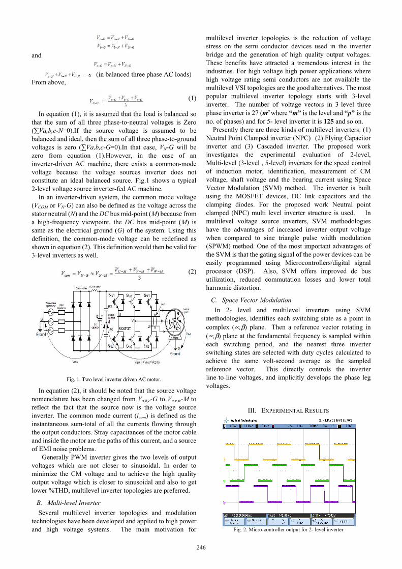
In equation (1), it is assumed that the load is balanced so that the sum of all three phase-to-neutral voltages is Zero (∑Va,b,c-N=0).If the source voltage is assumed to be balanced and ideal, then the sum of all three phase-to-ground voltages is zero (∑Va,b,c-G=0).In that case, VN-G will be zero from equation (1).However, in the case of an inverter-driven AC machine, there exists a common-mode voltage because the voltage sources inverter does not constitute an ideal balanced source. Fig.1 shows a typical 2-level voltage source inverter-fed AC machine.
In an inverter-driven system, the common mode voltage (VCOM or VN-G) can also be defined as the voltage across the stator neutral (N) and the DC bus mid-point (M) because from a high-frequency viewpoint, the DC bus mid-point (M) is same as the electrical ground (G) of the system. Using this definition, the common-mode voltage can be redefined as shown in equation (2). This definition would then be valid for 3-level inverters as well.
(2)
Fig. 1. Two level inverter driven AC motor.
In equation (2), it should be noted that the source voltage nomenclature has been changed from Va,b,c-G to Vu,v,w-M to reflect the fact that the source now is the voltage source inverter. The common mode current (icom) is defined as the instantaneous sum-total of all the currents flowing through the output conductors. Stray capacitances of the motor cable and inside the motor are the paths of this current, and a source of EMI noise problems.
Generally PWM inverter gives the two levels of output voltages which are not closer to sinusoidal. In order to minimize the CM voltage and to achieve the high quality output voltage which is closer to sinusoidal and also to get lower %THD, multilevel inverter topologies are preferred.
B. Multi-level Inverter Several multilevel inverter topologies and modulation
technologies have been developed and applied to high power and high voltage systems. The main motivation for
multilevel inverter topologies is the reduction of voltage stress on the semi conductor devices used in the inverter bridge and the generation of high quality output voltages. These benefits have attracted a tremendous interest in the industries. For high voltage high power applications where high voltage rating semi conductors are not available the multilevel VSI topologies are the good alternatives. The most popular multilevel inverter topology starts with 3-level inverter. The number of voltage vectors in 3-level three phase inverter is 27 (mp where “m” is the level and “p” is the no. of phases) and for 5- level inverter it is 125 and so on.
Presently there are three kinds of multilevel inverters: (1) Neutral Point Clamped inverter (NPC) (2) Flying Capacitor inverter and (3) Cascaded inverter. The proposed work investigates the experimental evaluation of 2-level, Multi-level (3-level , 5-level) inverters for the speed control of induction motor, identification, measurement of CM voltage, shaft voltage and the bearing current using Space Vector Modulation (SVM) method. The inverter is built using the MOSFET devices, DC link capacitors and the clamping diodes. For the proposed work Neutral point clamped (NPC) multi level inverter structure is used. In multilevel voltage source inverters, SVM methodologies have the advantages of increased inverter output voltage when compared to sine triangle pulse width modulation (SPWM) method. One of the most important advantages of the SVM is that the gating signal of the power devices can be easily programmed using Microcontrollers/digital signal processor (DSP). Also, SVM offers improved dc bus utilization, reduced commutation losses and lower total harmonic distortion.
C. Space Vector Modulation In 2- level and multilevel inverters using SVM
methodologies, identifies each switching state as a point in complex (∝,β) plane. Then a reference vector rotating in (∝,β) plane at the fundamental frequency is sampled within each switching period, and the nearest three inverter switching states are selected with duty cycles calculated to achieve the same volt-second average as the sampled reference vector. This directly controls the inverter line-to-line voltages, and implicitly develops the phase leg voltages.
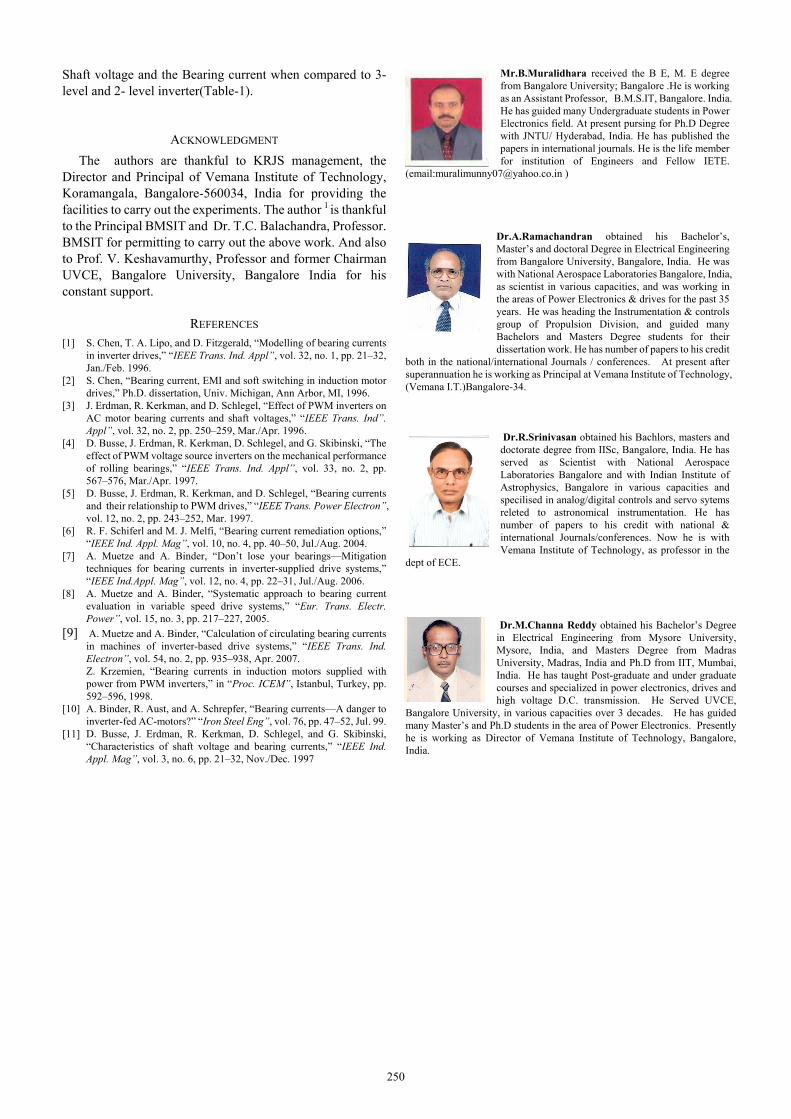
III. EXPERIMENTAL RESULTS
Fig. 2. Micro-controller output for 2- level inverter
246

Fig. 3. Gating signal generation (switching pattern) for 3-level inverter
Fig. 4. Gating signals of µ-controller output for NPC 5-Level NPC
inverter(only for top side devices).
Fig. 5. DSO recorded waveforms(2-level Inverter)
Ch 1: 200 : 1 Star point of IM to Gnd.
Ch 2: 200 : 1 Line voltage to IM.
Ch 3: 20 : 1 Vector sum of Ph current in terms of voltage.
Ch 4 1 : 1 Ph current in terms of voltage.
Fig. 6. DSO recorded waveforms(2-level inverter)
Ch 1: 200 : 1 Phase voltage to IM. Ch 2: 200 : 1 Line voltage to IM.
Ch 3: 20 : 1 Vector sum of current in terms of voltage. Ch 4: 1 : 1 One phase current in terms of voltage.
Fig. 7. DSO Recorded waveform. (3-level inverter)
Ch.1.200 : 1 Phase voltage.(2v/Div) Ch 2: 200 : 1 common mode voltage (1v/Div)
Ch 3: 1 : 1 Bearing current using the current probe
Fig. 8. DSO recorded waveform.(3-level inverter)
Ch 1: 200 : 1 Phase voltage Ch 2: 200 : 1 Line voltage Ch3: 1: 1 Vector sum of ph. current
Ch 4: 200 : 1 Common mode voltage
Fig. 9, DSO Recorded waveform (5-level NPC Inverter)
Ch 1: 200 : 1 Phase voltage (2V/div) Ch 2: 200 : 1 CM voltage (1V/div) Ch 3: 200 : 1 Shaft voltage(1V/div)
Fig. 10. DSO Recorded waveform (5-level NPC inverter)
Ch 1: 200 : 1 Phase Voltage Ch 2: 200 : 1 Line Voltage
Ch 3: 1 : 1 Sum of Ph. Current in terms of voltage Ch 4: 200 : 1 CM voltage
0 500 1000 1500 2000 25000
20
40
60
Frequency (Hz)
Am
plitu
de in
vol
ts
Fig. 11. FFT of Common mode voltage of IM. (20msec/Div,2-level
inverter)
0 400 800 1200 1600 20000
10
20
30
40
50
Frequency (Hz)
Am
plitu
de in
vol
ts
Fig. 12. FFT of CM voltage of IM (3-level inverter)
247

0 50 100 150 200 250 300 350 4000
10
20
30
40
50
Frequency (Hz)
Am
plitu
de in
vol
ts
Fig. 13. Expanded view of FFT of CM voltage (3-level inverter)
0 500 1000 1500 2000 25000
50
100
150
200
Frequency (Hz)
Am
plitu
de in
dB
μ V
Fig. 14. FFT of CM voltage of IM in dB µV(3-level inverter)
0 5 0 10 0 1 50 20 0 2 5 0 3 00 35 0 4 0 0 4 50 50 00
5 0
10 0
15 0
20 0
F re qu en c y (H z )
Am
plitu
de in
dB
μ V
Fig. 15. FFT of CM voltage of IM in dBµV (Expanded view, 3-level inverter)
0 500 1000 1500 2000 25000
10
20
30
Frequency (Hz)
Am
plitu
de in
Vol
ts
Fig. 16. FFT of Common mode voltage of IM in volts (5- level NPC inverter)
0 100 200 300 400 500 600 700 800 900 10000
2
4
6
8
10
F requ ency (H z)
Ampl
itude
in V
olts
Fig. 17. FFT of cm voltage of IM (X-Y expanded, 5-level NPC inverter)
0 500 1000 1500 2000 25000
50
100
150
200
Frequency (Hz)
Am
plitu
de in
dB
μ V
Fig. 18. FFT of common mode voltage of IM in DBµV(5-level NPC inverter)
0 400 800 1200 1600 2000 24000
10
20
30
40
Frequency (Hz)
Ampl
itude
in v
olts
Fig. 19. FFT of im shaft voltage in Volts(5-level NPC inverter)
-1000 0 1000 2000 3000 4000 50000
10
20
30
40
50
Frequency (Hz)
I.M.s
haft
& gn
d. v
olta
ge in
vol
ts
Fig. 20. FFT of IM shaft voltage (3-level inverter)
0 1000 2000 3000 4000 50000
20
40
60
Frequency (Hz)
I.M. s
haft
& gn
d. v
olta
ge in
vol
ts
Fig 21. FFT of I.M. shaft voltage (2-level inverter)
0 400 800 1200 1600 2000 24000
50
100
150
200
Frequency (Hz)
Ampl
itude
in d
B μV
Fig. 22. FFT of Shaft voltage in dB µV (5-level NPC inverter)
-100 0 100 200 300 400 500 600 700 800 900 10000
50
100
150
200
Frequency (Hz)
Ampl
itude
in d
B μ
volts
Fig. 23. FFT of Shaft voltage in dB µV (3-level inverter)
-100 0 100 200 300 400 500 600 700 800 900 10000
50
100
150
200
250
Frequency (Hz)
Am
plitu
de in
dBμ
V
Fig. 24. FFT of shaft voltage in dBμV (2-level inverter)
248

0 500 1000 1500 2000 25000
50
100
150
200
250
Frequency (Hz)
Am
plitu
de in
dB
μA
Fig. 25. FFT of Bearing current in µA(5-level NPC Inverter)
Fig. 26. FFT of bearing current in dBµA (3-level Inverter)
0 1000 2000 3000 4000 50000
50
100
150
200
250
Frequency (Hz)
Bea
ring
curre
nt in
dB
μ A
Fig. 27. FFT of bearing current in dBμA (2-level Inverter)
TABLE I: THE FFT OF COMMON MODE VOLTAGE, SHAFT VOLTAGE AND
THE BEARING CURRENT IN INVERTER FED INDUCTION MOTOR
Sl
No.
Inverter Level
FFT of CM Voltage
Frequency in Hz Value in volts
Value in dBµV
1.
2- Level Inverter
Fundamental frequency(40)
120 200 280 440
49 10 8 5 3
180 14 12 11 5
2.
3-Level Inverter
Fundamental frequency(40)
120 200 280 440
42 2 4 3 2
170 6 5 4 3
3
5- Level Inverter
Fundamental frequency(40)
120 200 280 440
36 1
2.5 3 1
160 1
1.5 2
0.8
Sl
No.
Inverter Level
FFT of Shaft Voltage with respect to gnd.
Frequency in Hz Value in volts
Value in dBµV
1.
2- Level Inverter
Fundamental frequency(40)
120 200 280 440
64 12 5 6 14
220 2 4 5
2.5
2.
3-Level Inverter
Fundamental frequency(40)
120 200 280 440
45 9 8 6 5
170 13 10 5 6
3
5- Level Inverter
Fundamental frequency(40)
120 200 280 440
38 5 7 4
1.5
155 10 9 7 2
Sl
No.
Inverter Level
Current flow from rotor shaft to the gnd through the Bearing (Bearing Current)
Frequency in Hz
Value in dBµA
1.
2- Level Inverter
Fundamental frequency(40)
120 200 280 440
220 1.5 1.3 1.2 1.1
2.
3-Level Inverter
Fundamental frequency(40)
120 200 280 440
145 2.2 2.1 1.9 1.9
3
5- Level Inverter
Fundamental frequency(40)
120 200 280 440
135 1.2 0.9 0.8 0.6
IV. CONCLUSION This work proposes a simple and efficient SVM method
that uses only outermost active voltage vectors. Due to these reasons the proposed SVM is computationally very simple and efficient. The research work presented in this paper is about the identification and the experimental measurement of the Common Mode Voltage in 2-level, 3-level and the 5-level (NPC) inverter fed induction motor drive and the technique of SVM scheme. This work also discusses identification as well as the experimental measurement of the rotor shaft voltage and the bearing current that is present in the modified squirrel cage three phase inverter fed induction motor drive. Figures 2, 3 and 4 shows the gating signal generation to the inverter circuits using micro-controller. Figures 5 to 10 shows the DSO recorded wave forms of the 2-level and multilevel Inverters. Figures 11to 27 shows the FFT results of the DSO Recorded waveforms using signal analysis software. The table-1 shows the comparison of the FFT results of the various parameters. It is observed experimentally by measuring the CM voltage and analyzing the same with FFT analysis using the Signal Analysis software that the 5-level inverters generates less CM voltage,
249
Shaft voltage and the Bearing current when compared to 3- level and 2- level inverter(Table-1).
ACKNOWLEDGMENT The authors are thankful to KRJS management, the
Director and Principal of Vemana Institute of Technology, Koramangala, Bangalore-560034, India for providing the facilities to carry out the experiments. The author 1 is thankful to the Principal BMSIT and Dr. T.C. Balachandra, Professor. BMSIT for permitting to carry out the above work. And also to Prof. V. Keshavamurthy, Professor and former Chairman UVCE, Bangalore University, Bangalore India for his constant support.
REFERENCES [1] S. Chen, T. A. Lipo, and D. Fitzgerald, “Modelling of bearing currents
in inverter drives,” “IEEE Trans. Ind. Appl”, vol. 32, no. 1, pp. 21–32, Jan./Feb. 1996.
[2] S. Chen, “Bearing current, EMI and soft switching in induction motor drives,” Ph.D. dissertation, Univ. Michigan, Ann Arbor, MI, 1996.
[3] J. Erdman, R. Kerkman, and D. Schlegel, “Effect of PWM inverters on AC motor bearing currents and shaft voltages,” “IEEE Trans. Ind”. Appl”, vol. 32, no. 2, pp. 250–259, Mar./Apr. 1996.
[4] D. Busse, J. Erdman, R. Kerkman, D. Schlegel, and G. Skibinski, “The effect of PWM voltage source inverters on the mechanical performance of rolling bearings,” “IEEE Trans. Ind. Appl”, vol. 33, no. 2, pp. 567–576, Mar./Apr. 1997.
[5] D. Busse, J. Erdman, R. Kerkman, and D. Schlegel, “Bearing currents and their relationship to PWM drives,” “IEEE Trans. Power Electron”, vol. 12, no. 2, pp. 243–252, Mar. 1997.
[6] R. F. Schiferl and M. J. Melfi, “Bearing current remediation options,” “IEEE Ind. Appl. Mag”, vol. 10, no. 4, pp. 40–50, Jul./Aug. 2004.
[7] A. Muetze and A. Binder, “Don’t lose your bearings—Mitigation techniques for bearing currents in inverter-supplied drive systems,” “IEEE Ind.Appl. Mag”, vol. 12, no. 4, pp. 22–31, Jul./Aug. 2006.
[8] A. Muetze and A. Binder, “Systematic approach to bearing current evaluation in variable speed drive systems,” “Eur. Trans. Electr. Power”, vol. 15, no. 3, pp. 217–227, 2005.
[9] A. Muetze and A. Binder, “Calculation of circulating bearing currents in machines of inverter-based drive systems,” “IEEE Trans. Ind. Electron”, vol. 54, no. 2, pp. 935–938, Apr. 2007. Z. Krzemien, “Bearing currents in induction motors supplied with power from PWM inverters,” in “Proc. ICEM”, Istanbul, Turkey, pp. 592–596, 1998.
[10] A. Binder, R. Aust, and A. Schrepfer, “Bearing currents—A danger to inverter-fed AC-motors?” “Iron Steel Eng”, vol. 76, pp. 47–52, Jul. 99.
[11] D. Busse, J. Erdman, R. Kerkman, D. Schlegel, and G. Skibinski, “Characteristics of shaft voltage and bearing currents,” “IEEE Ind. Appl. Mag”, vol. 3, no. 6, pp. 21–32, Nov./Dec. 1997
Mr.B.Muralidhara received the B E, M. E degree from Bangalore University; Bangalore .He is working as an Assistant Professor, B.M.S.IT, Bangalore. India. He has guided many Undergraduate students in Power Electronics field. At present pursing for Ph.D Degree with JNTU/ Hyderabad, India. He has published the papers in international journals. He is the life member for institution of Engineers and Fellow IETE.
(email:[email protected] )
Dr.A.Ramachandran obtained his Bachelor’s, Master’s and doctoral Degree in Electrical Engineering from Bangalore University, Bangalore, India. He was with National Aerospace Laboratories Bangalore, India, as scientist in various capacities, and was working in the areas of Power Electronics & drives for the past 35 years. He was heading the Instrumentation & controls group of Propulsion Division, and guided many Bachelors and Masters Degree students for their dissertation work. He has number of papers to his credit
both in the national/international Journals / conferences. At present after superannuation he is working as Principal at Vemana Institute of Technology, (Vemana I.T.)Bangalore-34.
Dr.R.Srinivasan obtained his Bachlors, masters and doctorate degree from IISc, Bangalore, India. He has served as Scientist with National Aerospace Laboratories Bangalore and with Indian Institute of Astrophysics, Bangalore in various capacities and specilised in analog/digital controls and servo sytems releted to astronomical instrumentation. He has number of papers to his credit with national & international Journals/conferences. Now he is with Vemana Institute of Technology, as professor in the
dept of ECE.
Dr.M.Channa Reddy obtained his Bachelor’s Degree in Electrical Engineering from Mysore University, Mysore, India, and Masters Degree from Madras University, Madras, India and Ph.D from IIT, Mumbai, India. He has taught Post-graduate and under graduate courses and specialized in power electronics, drives and high voltage D.C. transmission. He Served UVCE,
Bangalore University, in various capacities over 3 decades. He has guided many Master’s and Ph.D students in the area of Power Electronics. Presently he is working as Director of Vemana Institute of Technology, Bangalore, India.
250