experimental program for a plasma pinch space engine
TRANSCRIPT
IRVING GRANET and WILLIAM J. GUMAN
EXPE-WL PROGRAM-FOR A PLASM FmCH SPACE E N G m
TEE AUTHORS Irving Granet received his B.M.E. from The Cooper Union; his M.M.E. from Polytechnic Institute of Brooklyn; has taken Pre-Doctoral Studies at Po&- technic Institute of Brooklyn; and i s a graduate of the Oak Rid.ge SchooZ of Reactor Technology. He has worked in Republic's Plasma Propulsion Laboratory on nuclear pro- p u h systems, space radiators, thermodynamic power cycle considerations for generating electric power, and system design and operation fur %pace propulsion. H e wa8 fonnerly Director of Stu# Engineering, Nzlclear Energy Department, of Foster Wheeler Corporation where he directed engineering design and analysis for complete nuclear plants. Mr. Granet has taught thermodynamics and heut transfer at the Polytechnic Institute of Brooklyn, and at present is Adjunct Assistant Professor of Engineering and Physics at Long Island University. He has published over 40 articles in the @ids o f t h e r n w c l ~ n a k s , applied mechanics, heat transfer and nuclear energy. He is a member of the Anreri- can S o c i e ~ of Mechanical Engineers, N a h l Sociew of Professional Engi- neers, Pi Tau Sigma and Sigma Xi. He i s a licensed Professional Engineer in the State of N e w York. Mr. Granet i s listed in the 1960 edition of American M e n of Science and is a reviewer for the Amerkun Chemical Society's tech- nical publicatians.
William J . Guman received degrees of 8. Aero. E., M . Aero E., f7om and has completed courses for P U . Aero. E. at Rensselaer Polytechnic Institute. Since coming w Republic in 1959, M r . Guman h48 been conducting theore- tical and experimental studies on non-steady interactions and POU, processes in ptoSmn engine con+ration.s. Mr. Gumun was Assistant Professor tat Rensseluer Polytechnic Institute lecturing on fluid mtechnnics, d v & s , &ornuance and stability, and conducting lab0ratm-g courses in experi- mental fluid d ~ r n i c s and wind tunnel research. He also investigated induction and woad head of Rensseluer'a supers& wind tunnel laboram.
A.S.N.E. Jourml. November, 1961 n 745
PLASMA PINCH ENGINE EXPERIMENTS GRANGT & GUMAN
Mr. Guman performed a theoretical analysis in experimental aerodynamics at AVCO, and conducted analyses of experimental flight test data at Grum- mun. Mr. Guman huu authored papers published in the Journal of the Institute of The Aeronautical Sciences, Journal of Applied Physics, Journal of the American Rocket Society and the Physics of Fluids. Mr. Guman is listed in tke 1960 edition of American Men of Science and is a member of the Institute of the Aeronautical Sciences, Tau Betu Pi, Gamma Alpha Rho and sigma xi.
INTRODUCTION
IN A RECENT PAPER 111 the use of the electromag- netic pinch effect for space propulsion has been described in some detail. Theoretical studies using four analytical models were reported and certain significant conclusions were made based upon these studies. At the time that this earlier paper was writ- ten, experiments had been conducted and “proof of principle” had been established. Since that time, an extensive experimental program has been con- ducted at Republic’s Plasma Propulsion Laboratory and is reported in this paper, The field of plasma diagnostics is a very dililcult one due to the fact that it requires the ability to measure events occur- ring in less than one millionth of a second in the presence of large magnetic and electric fields. Since the process proceeds with velocities of the order of 100,000 miles per hour or greater, reliable measure- ments become very dficult to obtain.
Prior to discussing the experimental program it is briefly in order to answer two pertinent ques- tions, namely, “why have space missions?” and “where is each of the proposed propulsion systems applicable?” Table I 123 gives a partial listing of the many space missions that are desirable. As a last item, national prestige has been listed. Of all the reasons for space flight, this one should not be min- imized. It is necessary in the political atmosphere that exists at present in the world that the United States should demonstrate spectacular space accom- plishments. The balance of political power could easily rest on some spectacular, non-technical space shot.
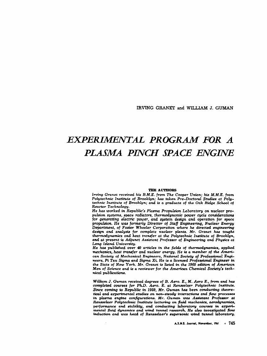
In order to answer the second question of ap- plicability of each of the proposed space propulsion systems it is necessary to make certain broad esti- mates. Figure 1, taken from many sources in the literature, gives the general range of performance and applicability of the most feasible propulsion systems. The ordinate is acceleration in “g’s’’ and represents the ratio of thrust to weight. Therefore, those systems whose “g” value is less than unity
YCLLCRATIOY
IN..’..
0 I , . I 1 . . . . I I I . . .,d 100 1000 m.ooo 100,000
S.tCIfIC I*P”LsL-sECS
Figure 1. Acceleration and Speei5c Impulse Spectrum.
cannot take off under their own power from earth. Only the chemical and nuclear fission devices can. The other coordinate, specific impulse is the ratio of velocity to “g” and represents the ratio of thrust developed to weight flow rate. Except for the mag- netohydrodynamic and ion engines, this figure shows that the maximum specific impulse is of the order of 1500 secs. This limitation is primarily due to materials limitations. The ion engine has difficul- ties at specific impulse less than 10,000 secs. arising from its extremely low efficiency in this range and there appears to be a major problem area due to electrostatic space charge phenomena.
The magnetohydrodynamic devices have a useful range of specific impulse ranging from 1,000 to 20,- 000 secs. System and mission studies performed at Republic C3l have indicated that for firesently con- ceived earth-orbit missions and for an earth-orbit to Mars-orbit mission the optimum specific impulse is in the range of from 1,000 to 7,000 secs. It should be noted that the magnetohydrodynamic devices fal l into two categories, pulsed and steady flow. As was indicated in C11, the pulsed device shows
certain advantages such as low average material temperatures, small loss of electrode material over extended operational periods, reliable start-stop operation, etc.
746 A.S.N.E. Journal, Novrmbrr, IWI

GRANET & GUMAN PLASMA PINCH ENGINE EXPERIMENT'S
TABLE I
TYPES OF FUNCTIONAL MISSIONS
I. Space Environment Missions IV. Communication Missions A. Physics
1. Atmospheric a. Composition b. Total density c. Electron and ion density d. Air glow or auroral
2. Magnetic fields 3. Micrometeorites 4. Cosmic radiations
a. Composition, direction, and energy b. Primary electrons and protons c. Primary gamma (x-rays) d. Ultraviolet and infra-red e. Light, color, and intensity f. Galactic noise, below ionospheric
cutoff B. Space environment
1. Exposure of: a. Materials b. Equipment c. Living things (recoveryis necessary)
Bacteria and yeast organisms
Rats Monkeys Man
Flowering plants
11. Astronomical and Astrophysical Missions
A. Propagation and ionospheric measure- ments 1. Electron density 2. Electron density above F-layer 3. Magneto-ionic ducts 4. Propagation
B. Satellite communication C. Worldwide communcaticm relays
1. Active 2. Passive (nonspherical)
V. Technological Missions
1. Geodetic 2. Relativistic effects on orbits, atomic
clock 3. Improvemept of tracking and launch-
guidance systems -4. Orbit modifications and transfer
1. Solar power collectors (parabolic) 2. Cooling radiators 3. Energetic liquids stored at low temper-
A. Precision orbital measurement for
B. Power Systems
ature and shielded from sun C. Stabilization systems for
1. Small payloads A.
B.
C. D.
Low-resolution optical scanning in ultra- violet and infra-red of the sun, moon, 3. Large payloads planets, and galaxy (stars, clouds, space). D. Guidance systems
2. Medium payloads
E. Space fight propulsion F. Reentry and recovery G. Manned Satellite
High-resolution optical survey in far ultraviolet of the sky Solar radiation Radio astronomy, below ionospheric cut- off of solar, planetary, galactic (stars) &, Transport and Supply Missions noise.
VII. Military Missbm A, Early warning B. Weapon delivery
111. Meterological Missions A. Cloud cover plus atmospheric heat bal-
ance B. Atmospheric heat balance only VIII. National Prestige
A.S.N.E. Journal. November, 1961 747
PLASMA PINCH ENGINE EXPERIMENTS GRANET & GUMAN
EXPERIMENTAL PROGRAM
GENERAL
In order to properly supplement the theoretical areas of investigation, Republic’s Plasma Propulsion Laboratory has designed, constructed and tested several test units specifically built and instrumented for research in the field of plasma physics. As an adjunct to this experimental program, Republic has accumulated considerable experience in the selec- tion and design of such equipment as switches (trig- gered gap switches, solenoid operated vacuum switches, ignitrons, thyratrons) ; capacitors; vacuum pumping and measuring equipment; high power transmission (coaxial cables, connectors, strip lines) ; insulation (ceramics, plastics) ; and induct- ance coils.
Experimental investigations in this field are diffi- cult and require carefully planned and executed diagnostic programs. Republic’s experience from both the theoretical and practical viewpoints is ex- tensive and detailed. The Plasma Propulsion Lab- oratory has developed and utilized advanced con- cepts of streak photography, ionization probes, light probes, magnetic probes, pressure transducers, etc. In addition, a considerable amount of experience has been gained in the placing of instrumentation to reduce its detrimental influence on the behavior of the plasma.
Some of the principal test units that have been used for these programs are:
Test Rig No. 1. Test Rig No. 2 Triggered Gap Switch. Fast Acting Gas Valve.
A brief description of these units in which their use and capability are indicated follows.
TEST RIG No. 1 Test Rig No. 1 has been used as a system for
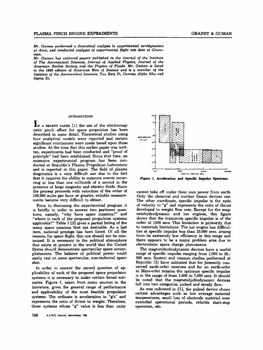
general experimentation with plasmas. Figure 2 is a photograph of Test Rig No. 1. It is on this rig that pinch experiments have been made using gas triggering and electrode nozzles to demonstrate the feasibility of a pulsed plasma pinch space engine. Considerable experience has been obtained on this rig with gas triggered discharges, and knowledge has been acquired on the requirements for obtain- ing this type of discharge between electrode nozzles of various shapes. In the course of this work, inter- esting data pertinent to a propulsion system have been obtained.
One of the most important considerations for an electric propulsion system is the initiation process, i.e., the processes affecting the establishment of a pinch, its stab&@ and its strength. In order to in- vestigate this fmdamental parameter, it was neces- sary to determine and develop certain circuit re-
748 A.S.N.E. Journal. Normmbor. IHI
F i r e 2. Test Rig No. 1 During Operation
quirements. To this end the current rise time and the ringing frequency of this rig have been altered by the insertion into the electrical circuit of coils of various values of inductance and resistance. These coils have been made at Republic and are used to vary the rate at which a pinch is propagated into the gas located in the inter-electrode spacing. The coils have been used particularly in stability studies of the action of a “slow” pinch and this work has been reported by T. Donner and L. Aron- owitz [41.
A streak camera has been used with this rig as have other forms of instrumentation, such as light probes for velocity measurement, pressure trans- ducers (Kistler gauge and barium titanate pellets) and current sensing coils in a plasma stream. Im- portant knowledge has been obtained of the effect of instrumentation on discharges and pinches and of the influence of temperature, pressure, magnetic fields and voltage on instrumentation. Valuable ex- perience has been acquired on the interpretation of instrumentation results and on the general tech- niques applicable to experimentation in this field.
TEST RIG NO. 2 Test Rig No. 2, designed for use in investigating
the production and acceleration of plasmas for space propulsion applications, has been operating success- fully far some time and valuable data have been obtained. The greater flexibility built into this test rig has been a major factor in obtaining extensive experimental data pertinent to the design of a space propulsion system. Figure 3 is a photograph of the unit showing all of the principal components and some of the instrumentation.
The components of Rig No. 2 are described in some detail in the following discussion:
Electrode Nozzles: Experience with aluminum

G R A ” & GUMAN PLASMA PINCH ENGINE EXPERIMENTS
Figure 3. Test Rig No. 2.
electrode nozzles has shown that they have very little erosion over long periods of operation and, furthermore, that the operational temperature of the nozzles stays less than 220OF. In these nozzles, the pinch is initiated by the introduction of the pro- pellant through a series of holes or slots near the outer periphery. Figure 4, a typical nozzle, has the top electrode removed and shows the propellant supply orifices.
The upper and lower electrodes are separated at the outer periphery by an electrical insulator. En- flon has been used successfully, and at no time was it found that arc-over from one of the electrodes to the other occurred due to the accumulation of debris at the surface of the insulator. Numerous electrode shapes have been tried, and the experi- mental results obtained on radially dominant, quar- ter circle and elliptic nozzles are presented in an- other section of this paper.
Capacitors: The pinch discharge depends upon low source impedance of a bank of capacitors for proper performance. It has been empirically deter- mined that at this experimental state of the art, re- liable pinchjng can be achieved at approximately 120 microfarads and 3000 volts. The present experi- mental rig uses industrial type capacitors that weigh two pounds per microfarad. Each of the ca- pacitors used is 30 microfarads and is capable of being charged to 6000 volts. A study program has been initiated at Republic with several prominent capacitor manufacturers to obtain small, light, re- liable high-energy capacitors. This is a continuing program and some benefits have already been de- rived and are incorporated in Prototype Test En- gine No. 3, which is described later in this paper.
Vacuum Chamber and Vacuum Pumping Sub- system: The vacuum chamber is 30 inches in diame- ter by 36 inches long, and is of welded aluminum construction. This chamber is presently operating
Fiure 4. Typical Nozzle Showing Propellant Supply Oriilces.
at vacua of lV4 mm Hg and has a capability of even lower pressures. Ultimates of 5x1V7 mm Hg have been achieved with the pumping system using water cooled baflles. The system is composed of six inch diffusion pumps, water cooled M e s , a me- chanical backing pump and a mechanical holding pump. In its present mode of operation, gas is in- jected into the chamber in pulses; each pulse being of the order of 5 ~ 1 P gms mass. The unit is capable of maintaining a vacuum of mm when it is pulsed at the rate of one pulse per second, demon- strating its capability to “clean up” this throughput. Port holes are provided for visual inspection and
streak photography. Connectors to plug-in instru- mentation and monitoring equipment are provided as shown in Figure 3.
Electrical Subsystem: The test rig is’operated by discharging a bank of capacitors across a shaped electrode assembly. The capacitors are stored in the cylindrical rack which is capable of acommoclating 20 units rated at a total capacity of 600 microfarads at 6000 volts. These units can be subjected to a dead short repeatedly without damage. The capacitors are connected to a central collection drum by low resistance, low inducthce coaxial cables to provide ease of arrangement, access and maintenance of the collectors. The entire circuit has an inductance of 0.030 microhenrys, including cappitors, cables, col-
A.S.N.E. Journal, Novornber. 1961 749

PLASMA PINCH ENGINE EXPERIMENTS GRANET & GUMAN
lector drum and electrodes. The system has a ring- ing frequency of 50 kilocycles per second under normal operation, showing a rise time of five micro- seconds to maximum current in the fmt quarter cycle. A significant finding is that a fast current rise
contributes to the early formation of a good current sheath, one of the essentials to obtain a stable pinch. With fast current rise (even with minimum energy levels), stable pinches have been obtained without external pre-ionization, other than normal background radiation.
Several power supplies are available that can charge the capacitors in times ranging from less than one second to several seconds.
Control Console: The console shown in Figure 3 contains the controls for the general operation and monitoring of the engine system. Automatic se- quencing circuits are provided such as that for the operation of a streak camera. In this circuit, after the initial parameters of the experiment are estab- lished, the operation of the streak camera is auto- matically keyed in to make each exposure at the correct time. The console also contains a panel to control the operation of the gas valve. The frequen- cy as well as the duration of the gas pulse can be controlled from the console.
Triggered Gap Switch An experimental assembly utilizing the inverse
pinch process was devised as an application of the inverse pinch to develop a triggered gap switch. Republic is interested in the use of such a high- energy switch for application in pulsed plasma de- vices in order to take advantage of the self-extin- guishing feature of such a geometry. The equipment is also being used for general investigation into the physics of an inverse pinch, particularly in its ap- plication as a high current density switch. The unique feature of this device is F t it can be used both as a switch and a valve for controlling propel- lant injection. Figures 5 and 6 show the triggered gap switch developed at the Plasma Propulsion Laboratory at FkpuWc.
It
Figure 6. V i m of Triggmd Gap Switch
Fast Acting Cas Valve During the early investigations, it was realized
that gas triggering of high energy discharges was advantageous. Such a mode of operation eliminates the need for a triggered gap switch in a propulsion system. This form of initiation has now become standard at Republic and is utilized in all propul- sion experiments. Although commercial valves can be used for this purpose, it is readily apparent that some applications require better gas utilization and propellant injection control than is available with commercial equipment. In an attempt to meet some of these requirements, Republic has been develop- ing a valve of unusual design. Several valves and their assorted electrical circuits have been made and are currently being evaluated.
DIAGNOSTICS
The ultimate purpose of an engine for space pro- pulsion is to provide thrust for the specified mission efficiently so that the total weight of the propulsion system is minimized. In order to properly design a device to meet this objective, it is necessary to be knowledgeable in all subsystem areas pertinent to the engine. In this section the parameters of par- ticulag interest for engine development are categor- ized. Diagnostic equipment and pertinent specific test data will be presented. The areas of interest and also those in which the Plasma Propulsion Lab- oratory has expanded a great deal of experimental effort are:
Velocity of the plasma in the engine and the ve- locity of d u x of the plasma from the engine.
Mass of propellant injected per pinch and the mass of propellant actually involved in the electro-gas dynamical processes after initiation of the pinch.
Thrust of the device. Electrodynamic parameters of the system. Pinch initiation requirements. It must be emphasized that the electro-gas dy-
namical transients associated with such an engine require diagnostic ability to obtain reliable data in times of the order of one microsecond or less in the presence of extremely large transient magnetic
750 A.S.N.E. Journal, November. 1961

G R A " & GUMAN
fields. Therefore, in each of the foregoing areas, sev- eral techniques have been used to obtain reliable, reproducible data. In the following material some of the pieces of special test equipment in use at the Plasma Propulsion Laboratory are briefly described prior to the presentation of specific experimental results.
Rotating Drum Camera Republic (in conjunction with Photo Mechan-
isms,, Inc.) designed and built a high speed rotat- ing drum camera. This camera monitors the movement of a plasma over a length of 12 inches from a distance of 20 inches. When the fdm is pro- jected to full scale, the time resolution is four microseconds per inch. Ten microsecond timing markers and a zero time mark are placed on the film simultaneously with the exposure of each event. Figure 7 shows this camera as used in Test Rig No. 1. Rotating Mirror C a w a
A rotating mirror camera has recently been pur- chased. Continuous optical records of the plasma motion can be obtained by means of hexagonal mir- ror rotating up to 3000 rps. At the peak speed, the mirror provides a writing speed of 3.9 millimeters per micrasecond for a total writing time of 50 microseconds. The 70-mm wide film used provides
PLASMA PINCH ENGINE EXPEXMEWIS
large images which enhance the accuracy in the data reduction. Typical. test results obtained with this camera are shown in Figures 8 and 9.
Light Probes Two photocells (1P42) spaced a known distance
apart have been used to determine the leading edge plasma velocity leaving a given nozzle as well as plasma front velocity distribution beyond the vzzle
circus 9. Tppial stre&pbobgnpb--Fslm AlatlOn M- Figure 7. Inskummtation on Teat Big No. 1. lel to Thrust Art.
A.S.N.E. J w r r l . Nwombor. 1961 751
PLASMA PINCH ENGINE EXPERIMENTS GRANET & GUMAN
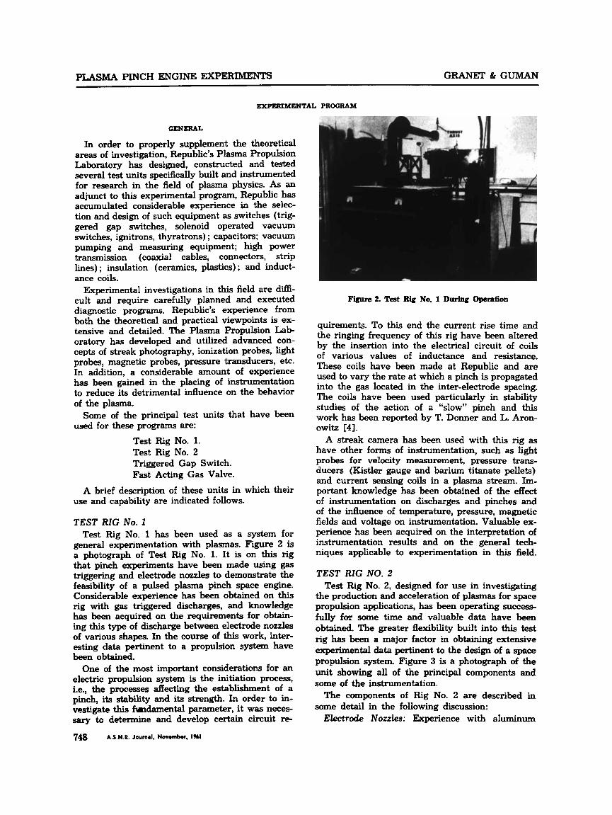
exit. The technique used is essentially that em- ployed by other investigators in the field of plasma physics. This technique has been refined consider- ably through the extensive use of light shields, long light tubes and electrical shielding. A typical light
probe installation is shown in Figures 10, 11, and 12. A typical result is shown in Figure 13.
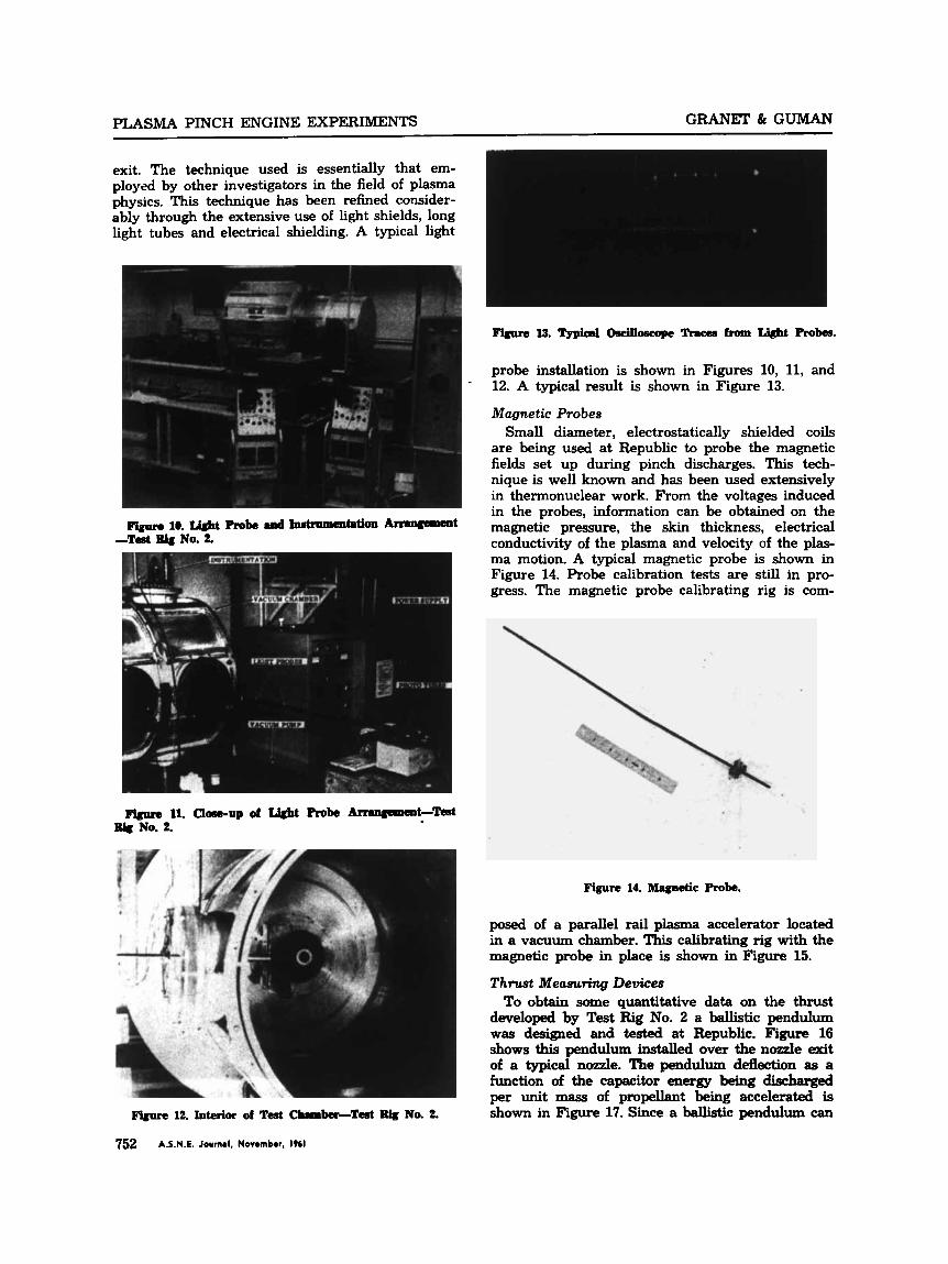
Magnetic Probes Small diameter, electrostatically shielded coils
are being used at Republic to probe the magnetic fields set up during pinch discharges. This tech- nique is well known and has been used extensively in thermonuclear work. From the voltages induced in the probes, information can be obtained on the magnetic pressure, the skin thickness, electrical conductivity of the plasma and velocity of the plas- ma motion. A typical magnetic probe is shown in Figure 14. Probe calibration tests are still in pro- gress. The magnetic probe calibrating rig is com-
P ’ b w 10. Wt Probe .ad Inatmmmtati~ ArnaCcansnt -Ted RJg No. 2.
Figure 14. Magnetic Robe.
posed of a parallel rail plasma accelerator located in a vacuum chamber. This calibrating rig with the magnetic probe in place is shown in Figure 15.
T h r w t Measuring Devices To obtain some quantitative data on the thrust
developed by Test Rig No. 2 a ballistic pendulum was designed and tested at Republic. Figure 16 shows this pendulum installed over the nozzle &t of a typical nozzle. The pendulum deflection as a function of the capacitor energy being dischaged per unit mass of propellant being accelerated is shown in Figure 17. Since a ballistic pendulum can Figure 12. Interior of Test Cbrmb6r-Ted No. 2.
752 A.S.N.E. Journal. Novombor, 1961

GRANET & GUMAN PLASMA PINCH ENGINE EXPERIMENTS
12
10
U
f Y O n 5 R
E
z 0 6
2 U
Y
I 3 . a w
2
PENDULlJh: DEFLEClION AS A FUNCTION OF THE CAPACITOR ENERGY PER UNIT MASS OF PROPELLANT
( T E S T ENGlNE*Z I
INITIAL PROPELLAN1 PRESSUnE SO mm Hp
- 0 100 mm Hq
0 IS0 mm Hq
r .
~ .. -
0 10 2 0 XI 4 0
CAPICITOR ENERGY PERUNIT M 4 S S ( z L - E - S n 10a)OF PROPELLh1.T KP
Figure 17. Ballistic Pendulum Test Results.
never truly give correct thrust readings of a pulsed plasma accelerator, work is now in progress to sus- pend a self contained plasma pinch engine on a pen- dulum type thrust stand. The engine and the thrust stand will be mounted in a large vacuum chamber. The latest design of the thrust stand will support the engine in an inverted vertical cantilever fashion on modular flexures. The restoring moment of the flexures is couiiteracted by an adjustable counter- poise. An adju5table damping unit will also be pro- vided. This instrument, shown in Figure 18, will provide accurate readings of the thrust developed by the plasma pinch engine taking into account the thrust developed by the momentum efflux as well as the pressure forces generated. Based upon these thrust measurements the ballistic pendulum will be calibrated.
Figure 15. Wch Rig for Wbrnti011 Of m@dC Probes.
1
STEADY STATE CALIBRATOR (LEVER TYPE)
I IMPULSE CALIBRATOR .UM TYPE)
/
ELECTRICAL POWER’
Figure 16. Ballistic Pendulum M ~ m t e d in Test IUg No. 2. Figure 18. Roposed Thrust Staod-Aerosfhce, hc.
A.S.N.E. Journal. Novombr. IT61 753

GFtA.NET & GUMAN PLASMA PINCH ENGINE EXPERIMENTS
Surface Thermocozlples Two surface thermocouples have been obtained
for the purpose of measuring the surface tempera- ture as well as for “time-of-arrival” measurements. These thermocouples have a response of less than a microsecond. This rapid response is achieved by having the thermal junction of the surface thermo- couple at the interface of a polished coaxial assem- bly and a junction thickness of only one micron. One of these thermocouples is shown in Figure 19.
Figure IS. m i d Response Surface Thermocouple.
Schlieren Shadowgraph System The Schlieren Shadowgraph system shown in
Figure 20, has been designed and built to study the flow of moving plasma in the region of objects in- serted in its path and to obtain density gradients in various regions of flow. Furthermore, the equip- ment can be used to analyze the flow and distribu- tion of gases between electrodes and also in the vacuum chamber in the absence of an electrical discharge. This system is designed to contribute in- formation to improve the design of gas triggering equipment (to aid in the establishment of the best time for pinch or discharge after gas injection and to give indications of the rate of expansion of gas into the vacuum chamber). This system will be used in conjunction with a pulsed Kerr Cell to map flow and density patterns at precise times after initiation. Streak back lighting has also been at- tempted. A Kerr Cell having an ef€ective exposure time of five millimicroseconds mounted on Test Rig No. 1 is shown in Figure 7.
Velocity Spectrometer A probe was developed to discern the velocity of
electrons and ions in a localized area of a low den- sity moving plasma. This probe, shown in Figure 21, is used to map out the variation of particle velocity at Merent distances and positions from the plasma
754 A.S.N.E. Journal, Novombot. IT61
Fiignm 21. velocity speehurmeter.
source. To accomplish this, a narrow beam of plas- ma is directed into a cavity across which a mag- netic field is applied. The field causes separation of particles to either side of the beam, according to their charge. Two plates are placed in the paths of the particles, one for the negative stream and one for the positive. A “stopping” potential can now be applied to each plate and by variation of the po- tentials the particles can be stopped. From the po- tentials applied, an estimate can be made of the particle speed. The plot of the percentage of par-
GRANET & GUMAN PLASMA PINCH ENGINE EXPERIMENTS
ticles stopped for each applied potential gives an indication of the distribution of velocities within the sample taken.
Experimental Results
In this section, specific experimental results are cited which were obtained at the Plasma Propul- sion Laboratory, and which are pertinent to the understanding and evaluation of a space propulsion system utilizing the pinch process. 0
Plasma Velocity One of the significant parameters of interest in a
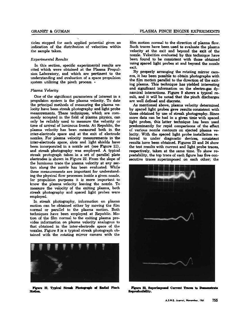
propulsion system is the plasma velocity. To date the principal methods of measuring the plasma ve- locity have been streak photography and light probe measurements. These techniques, which are com- monly accepted in the field of plasma physics, can only be reliably used to measure the velocity or time of arrival of luminous fronts. At Republic, the plasma velocity has been measured both in the inter-electrode space and at the exit of electrode nozzles. For plasma velocity measurements in the inter-electrode space, slots and light shields have been incorporated in a nozzie set (see Figure ll), and streak photography was employed. A typical streak protograph taken in a set of parallel plate electrodes is shown in Figure 22. From the slope of the luminous trace the plasma velocity at any sec- tion along the nozzle has been evaluated. While these measurements are important for understand- ing the physical flow processes inside a given nozzle, for propulsion purposes it is more important to know the plasma velocity leaving the nozzle. To measure the velocity of the exiting plasma, both streak photography and spaced light probes were employed.
In streak photography, information on plasma motion can be obtained either by moving the film normal or parallel to the plasma motion. Both techniques have been employed at Republic. Mo- tion of the film normal to the exiting plasma pro- vides information on plasma velocity analogous to that obtained in the inter-electrode space of the nozzles. Figure 8 is a typical streak photograph ob- tained with the rotating mirror camera with the
film motion normal to the direction of plasma flow. Such traces have been used to evaluate the plasma velocity at the exit and beyond the exit of the nozzle. Velocities evaluated by this technique have been found to be consistent with those obtained using spaced light probes at and beyond the nozzle exit.
By properly arranging the rotating mirror cam- era, it has been possible to obtain photographs with the film motion parallel to the direction of the exit- ing plasma. This technique has yielded interesting and sisnificant information on the electro-gas dy- namical interactions. Figure 9 shows a typical re- sult, and it will be noted that the pinch discharges are well defined and discrete. As mentioned above, plasma velocity determined
by spaced light probes gave results consistent with those obtained by use of streak photography. Since more data can be had in a given tinie with spaced light probes, this latter technique has been used predominantly for rapid comparisons of the effect of various nozzle contours on ejected plasma ve- locity. With the spaced light probe installation re- ferred to under diagnostic devices, consistent results have been obtained. Figures 23 and 24 show the test results with current and light probe traces, respectively, taken at the same time. To show re- peatability, the top trace of each figure has five con- secutive traces superimposed on each other; the
PLASMA PINCH ENGINE EXPERIMENTS GRANET & GUMAii
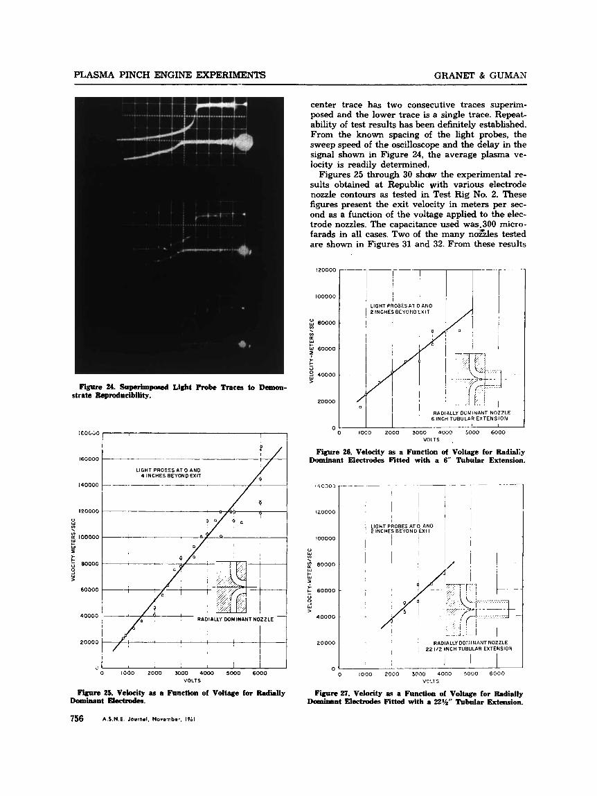
center trace has two consecutive traces superim- posed and the lower trace is a single trace. Repeat- ability of test results has been definitely established. From the known spacing of the light probes, the sweep speed of the oscilloscope and the delay in the signal shown in Figure 24, the average plasma ve- locity is readily determined,
Figures 25 through 30 shaw the experimental re- sults obtained at Republic with various electrode nozzle contours as tested in Test Rig No. 2. These figures present the exit velocity in meters per sec- ond as a function of the voltage applied to the elec- trode nozzles. The capacitance used was.300 micro- farads in all cases. Two of the many nozles tested are shown in Figures 31 and 32. From these results
Figure 24. Superimposed Light Robe Traces to Demon- strate Reproducibility.
IEO(130
I60000
140000
120000
V IU v)
v)
w W
LI 100000
: 5 80000 9 W
60000
40000
20003
P I -______ /
LIGHT PRO?ES AT 0 A N 0 4 INCHES BEYOND EXIT
7 ~~~~
0 1000 2000 moo0 4000 SO00 6000 VOLTS
Figure 25. Velocity as a Function of Voltage for Radially Dominent Electrodes.
756 A S.N.E. Journal. November. 1961
l20000
100000
: eoooo v) . In
W
60000 7 k
9 40000 0
W
20000
I I I 1 I
0 1000 2000 3000 4000 GOO0 6000 VOLTS ,
Figure 28. Velocity as a Function of Voltage for Radialiy Dominant Electrodes Fitted with a 6" Tubular Extension.
1 'I 00oCJ
l20000
100000
0
% g 80000 L 5
f:
W
60000 V
W > 40000
20000
0
- ~ _ _ _ - _ _ _ _
LIGHT PROBES I 1 AT 0 AN0
2 INCHES EEYONO EXIT
! I
- 1 . -
, RADIALLY 0OI.iINANT NOZZLE ~ 22 1/2 INCH TUBULAR EXTENSIC I I
j 1 I
0 1000 2000 3000 4000 5000 6000 VCLTS
F m 27. Velocity as a Function of Voltage for Radially Dominant Electrodes Fitted with a 22%" Tubular Extension.

GRANET & GUMAN PLASMA PINCH ENGINE EXPERIMENTS
~
REDUCED DIAMETER I I 1 I OUARTERCIRCLENOZZLE I
I
0 1000 2000 3000 4000 5000 6000 VOLTS
Figure 28. Velocity as a Function of Voltage for a Re- duced Diameter Quarter Cirde Electrode.
160000
140000
I 2 C C 3 0
V w n
u) (r W
b- W
>
u 0 -I
\ 100000
7 80000 k
60000
40000
20000
0
Figure 29. Velocity as a FnnetiOn of Voltage for a Quar- ter C i l e Electrode.
160000
140000
120000
:: 100000
(r W I- W I. I 80000 > t V 0 -I $! 60000
40000
20000
0
ELLIPTIC NOZZLE MAJOR AXIS HORIZONTAL
0 1000 2000 3000 4000 5000 6000 VOLTS 0 ,
Figure 30. Velocity as a Function of Voltage for an Ellip- tic N o d e with the Major Axis HorizOntaL
Figure 31. Typical Nozzle Sct-Elliptic with Major Axis Horizontal.
F m 32. Typical N o d e Set-Ibdi.lly Domhunt.
A.S.N.E. Journal, Norwnbw. 1961 757
PLASMA PINCH ENGINE EXPERIMENTS GRANET & GUMAN
it has been concluded that some nozzle configura- tions are not too well suited for a practical propul- sion device. However, such configuration as a nozzle whose center-line is a quarter circle and which has an inter-electrode gap spacing of one-half inch, as well as radially dominant nozzles, appear to be well suited for propulsion applications. For example, Figure 25 shows the test results obtained with the radially dominant nozzles. By varying the applied voltage from 800 to 6000 volts, the exit velocity was found to vary from about 20,000 meters per second to about 170,000 meters per second. If one can talk of a "local specific impulse," this would encompass a range from 2000 to 17000 seconds. For a given applied voltage the quarter circle nozzle referred to accelerated the ejected plasma to an even higher velocity. Figure 29 shows the test results with these quarter circle nozzles. It will be noted that for the nozzle shapes tested the exit velocity varied linear- ly with the applied voltage over the range of vari- ables investigated.
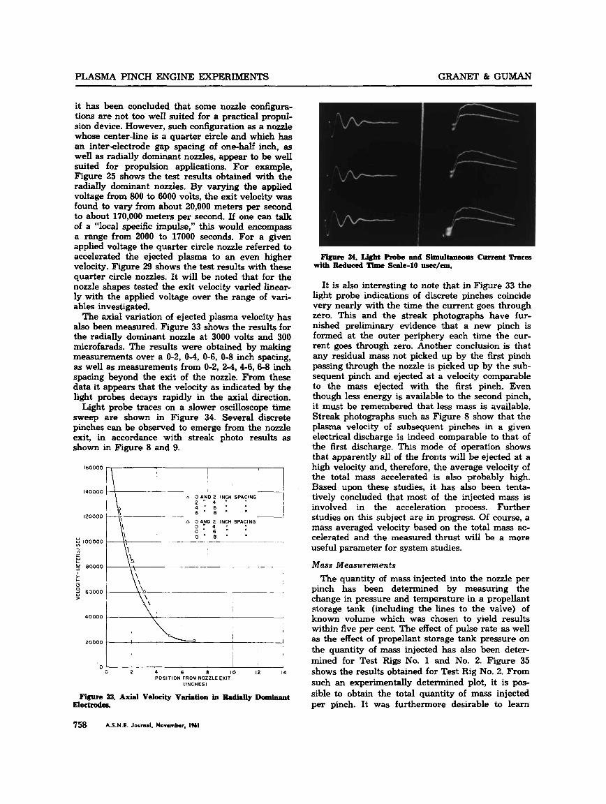
The axial variation of ejected plasma velocity has also been measured. Figure 33 shows the results for the radially dominant nozzle at 3000 volts and 300 microfarads. The results were obtained by making measurements over a 0-2, 0-4, 0-6, 0-8 inch spacing, as well as measurements from 0-2, 2-4,4-6, 6-8 inch spacing beyond the exit of the nozzle. From these data it appears that the velocity as indicated by the light probes decays rapidly in the axial direction.
Light probe traces on a slower oscilloscope time sweep are shown in Figure 34. Several discrete pinches can be observed to emerge from the nozzle exit, in accordance with streak photo results as shown in Figure 8 and 9.
160000
1 4 0 0 0 0
120000
2 100000 . n ci w
g 80000 r t
60000 5
4 0 0 0 0
20000
I 1 I
o 0 AFD 2 INCH SPACING
6 " 8 " "
2 4 , I ,, I I I 1
h 0 AND 2 INCH SPACING I
I 0 ' 8 . - i 77 _ _ _ - -I
\'A
1
I 4
1 I
! I 'I
I I I
! 'I
I I I
0 0 2 4 6 8 10 I2 14
[INCHES) POSITION FROM NOZZLE EXIT
Fisurc 33. Axial Velocity Variation in Sadially Dominant EltXtZOdSa
758 A.S.N.E. Journal, November, 1961
Figure 34. Light Probe and Simultaneous Current Traces with Reduced Timc scale-10 usec/an.
It is also interesting to note that in Figure 33 the light probe indications of discrete pinches coincide very nearly with the time the current goes through zero. This and the streak photographs have fur- nished preliminary evidence that a new pinch is formed at the outer periphery each time the cur- rent goes through zero. Another conclusion is that any residual mass not picked up by the first pinch passing through the nozzle is picked up by the sub- sequent pinch and ejected at a velocity comparable to the mass ejected with the first pinch. Even though less energy is available to the second pinch, it must be remembered that less mass is available. Streak photographs such as Figure 8 show that the plasma velocity of subsequent pinches in a given electrical discharge is indeed comparable to that of the first discharge. This mode of operation shows that apparently all of the fronts will be ejected at a high velocity and, therefore, the average velocity of the total mass accelerated is also probably high. Based upon these studies, it has also been tenta- tively concluded that most of the injected mass is involved in the acceleration process. Further studies on this subject are in progress. Of course, a mass averaged velocity based on the total mass ac- celerated and the measured thrust will be a more useful parameter for system studies.
Mass Measurements
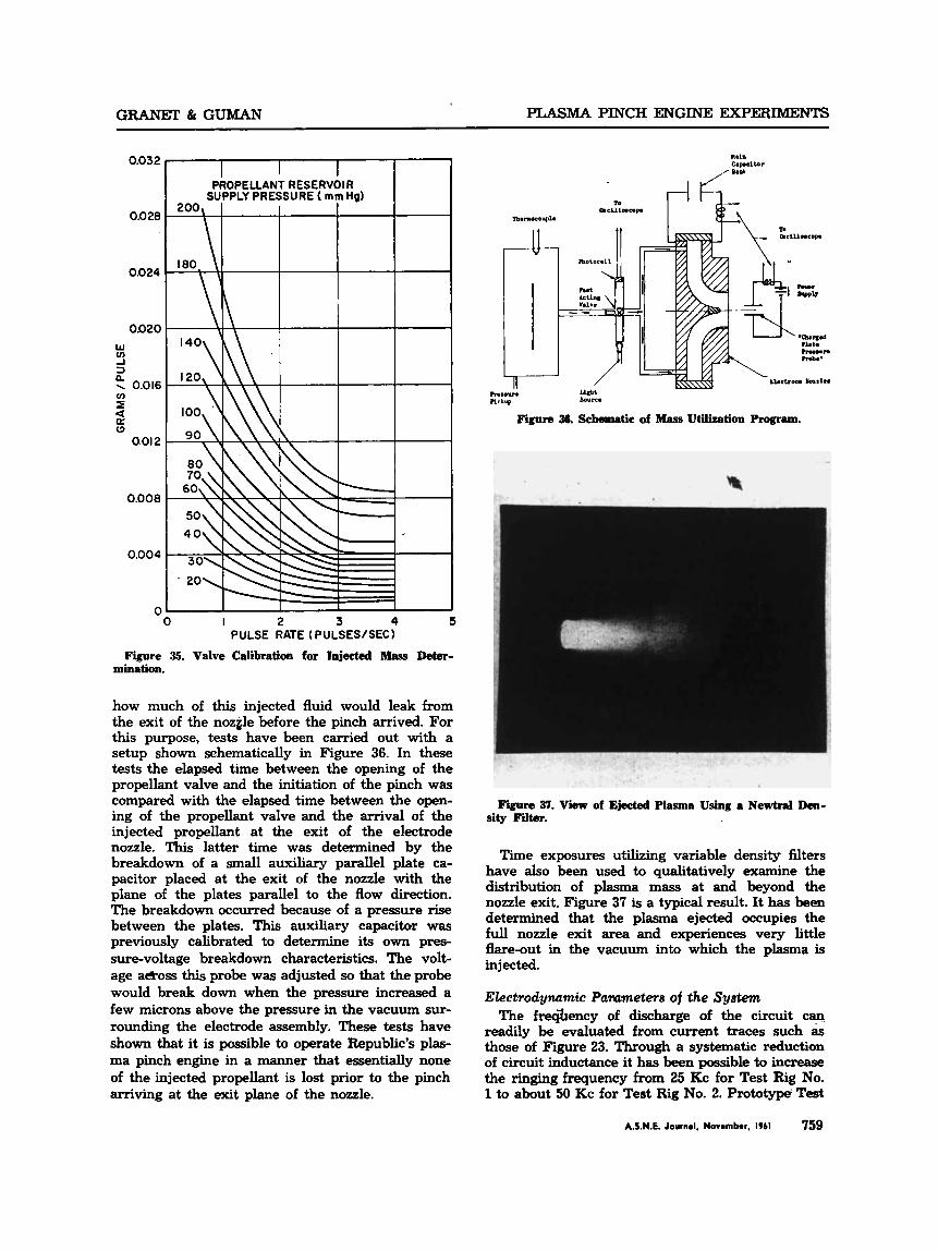
The quantity of mass injected into the nozzle per pinch has been determined by measuring the change in pressure and temperature in a propellant storage tank (including the lines to the valve) of known volume which was chosen to yield results within five per cent. The effect of pulse rate as well as the effect of propellant storage tank pressure on the quantity of mass injected has also been deter- mined for Test Rigs No. 1 and No. 2. Figure 35 shows the results obtained for Test Rig No. 2. From such an experimentally determined plot, it is pos- sible to obtain the total quantity of m a s injected per pinch. It was furthermore desirable to learn
GRANGT & GUMAN PLASMA PINCH ENGINE EXPERIMENTS
0.032 I I I I
0.028
0.024
0.020 W UJ -.I 3 0 \ 0.016 UJ E
(3
a a 0.01 2
0.008
0.004
PROPELLANT RESERVOIR SUPPLY PRESSURE ( mm Hg)
200,
I
0' I I 1 I 1
0 I 2 3 4 5 PULSE RATE (PULSEWSEC)
Figure 35. Valve Calibration for Injected Mass Deter- mination.
how much of this injected fluid would leak from the exit of the noz&le before the pinch arrived. For this purpose, tests have been carried out with a setup shown schematically in Figure 36. In these tests the elapsed time between the opening of the propellant valve and the initiation of the pinch was compared with the elapsed time between the open- ing of the propellant valve and the arrival of the injected propellant at the exit of the electrode nozzle. This latter time was determined by the breakdown of a small auxiliary parallel plate ca- pacitor placed at the exit of the nozzle with the plane of the plates parallel to the flow direction. The breakdown occurred because of a pressure rise between the plates. This auxiliary capacitor was previously calibrated to determine its own pres- sure-voltage breakdown characteristics. The volt- age a&oss this probe was adjusted so that the probe would break down when the pressure increased a few microns above the pressure in the vacuum sur- rounding the electrode assembly. These tests have shown that it is possible to operate Republic's plas- ma pinch engine in a manner that essentially none of the injected propellant is lost prior to the pinch arriving at the exit plane of the nozzle.
Figure 36. Scheauatic of Mass Utilization Program.
Figure 37. View of Ejected Plasma Using a Newtral Dem- sity Filter.
Time exposures utilizing variable density filters have also been used to qualitatively examine the distribution of plasma mass at and beyond the nozzle exit. Figure 37 is a typical result. It has been determined that the plasma ejected occupies the full nozzle exit area and experiences very little h e - o u t in the vacuum into which the plasma is injected.
Electrodynamic Parameters of the System The f q a e n c y of discharge of the circuit can
readily be evaluated from current traces such & those of Figure 23. Through a systematic reduction of circuit inductance it has been possible to increase the ringing frequency from 25 Kc for Test Rig No. 1 to about 50 Kc for Test Rig No. 2. Prototypei Test
A.S.N.E. Journal. Novmbw. 1961 759

PLASMA PINCH ENGINE EXPERIMENTS GRANET & GUMAN
Figure 38. Voltage Breakdown Curve for Nitrogen-Test Ri le No. 1 and 2-Radially Dominant Aluminum Electroder.
Engine No. 3 will have a higher ringing frequency than Test Rig No. 2. It has already been pointed out that the higher ringing frequency is desirable from the point of view of pinch initiation.
The inductance of Test Rig No. 2 was calculated from measurements of the ringing frequency, f, as the capacitor bank was decreased from 10 capaci- tors to 5 capacitors. (The capacitors were 30 micro- farads each.)
It was assumed that the resistance of the rig was negligible and that the inductance, L, is given by:
L, + L, L= ___ n
Where
L, = inductance of a single capacitor and its connect-
L,= inductance of the remainder of the circuit ing cable
n=rlumber of capacitors in the bank
When the measured data were fitted to the equa- tion by the method of least squares, the following values were obtained.
L, = 1.56 x 1C8 henrys L, = 2.43 x lCT henrys
Thrust Early estimates of the thrust were based on
knowing the quantity of mass injected and velocity of the plasma ejected. To further demonstrate the thrust-developing capabilities of the vertically mounted Test Engine No. 1, a specially designed lightweight cup was placed in the stream of the ejected plasma. This technique had many shortcom- ings. To obtain some quantitative data of the thrust developed by Test Rig No. 2, a specially designed ballistic pendulum was used (Figure 16). The pen- dulum deflection was measured and plotted as a function of the stored capacitor energy per unit mass of plasma ejected. The results are shown in Figure 17. Since such a ballistic pendulum can never truly measure the thrust developed by a non- steady pulsed device ejecting compressible plasma, it is intended to mount the self-contained Prototype Engine No. 3 on a pendulum type thrust stand in a vacuum chamber, Most of the preliminary studies on this have already been carried out, and the thrust measuring device referred to earlier will be available for testing in the near future.
Pinch Initiation In the Republic pulsed plasma pinch engine, the
pinch is initiated by the injection of gas into the inter-electrode space near the outer periphery. For both a fundamental understanding of the formation of the pinch as well as to obtain data necessary for the reliable operation of the engine, experimental
TABLE I-(TEsT RIG No. 2 ) Study of Low Energy Pinches To Relate the Pinch Plasma Phenomena
T o Discharge Energy and Current
~
6A I 120 100 0.2 735 5.75 1 yes 1 regatofitem6 PI Inlet Pressure (nun Hg) Pt Chamber Pressure (mm Hg)
760 A.S.N.E. Journal. Novwnbu. 1961

GRANET & GUMAN PLASMA PINCH FNGINE EXPERIMENTS
studies on the initial breakdown characteristics of the propellant in the inter-electrode space have been performed. Figure 38 shows the voltage-pres- soure breakdown curves (Paschen curves), for the radially dominant nozzles in both Test Rigs No. 1 and No. 2 with nitrogen under static conditions. It has also been determined that these curves are a function of the electrode surface conditions and the gas used. By reference to these curves it has been possible to predict the proper operating voltage levels for the case of injected propellant.
Since efficient energy utilization is obviously of importance to a space propulsion device, an effort has been made to study the minimum energy re- quirements for a pinch as a function of system re- quirements. Table I shows some of the data from these studies taken on Test Rig No. 2 with a con- stant capacitance of 120 microfarads. This table shows whether a pinch was formed at all and the type of pinch, all based upon streak photographs of the inter-electrode space. Data on other gases and gas mixtures have, also been taken as part of this overall program.
The third item under the heading of pinch initia- tion that has been investigated is the study of time lags in gaseous discharges. Preliminary work re- ported in Republic’s AFOSR TN-60-59 111 indicates that the time lag in the discharge is a function of capacitor energy, pressure and type of gas. It was concluded that the greater the capacitor energy and gas pressure the shorter the time lag. There is also a sharp decrease in the time lag once a critical ca- pacitor voltage is exceeded.
The entire program of pinch initiation is a con- tinuing part of the fundamental and applied studies being investigated in the Plasma Propulsion Labo- ratory.
ACKNOWLEDGMENT
The authors wish to acknowledge the invaluable aid of Messrs. e. C. Cavalconte and A. Steinberg in devising some of the test equipment, setting it up, and in carrying out some of the work described in this report. In addition, the cooperation of Messrs. William Johnson, H. Latz, and E. Poggi in the execution of this program is gratefully acknowl- edged. Since it is not possible to mention by name all of the personnel who individually contributed in some measure to this work; the writers take this opportunity to collectively thank them. This work was sponsored in part by the Office of
Naval Research under Contract Nonr-2851(00) and in part by the Air Force Office of Scientific Re- search under Contract AF’49 (638) -552.
REFERENCES
Granet, I., Guman, William J., and Mcnroy, W., “Studies of a Plasma Pinch Space Engine,” A S N E Journal, November 1960, pp. 715-725. Unterman, M., Republic Aviation,+rporation, Plasna Propulsion Project Private Communication. McIlroy, William, Republic Aviation Corporation, Plas- ma Pro ulsion Project, Private Communication. D o n n e r ~ . and Aronowitz, L., “Experimental Investi- gations of Electromagnetically Induced Detonatio- Part I-Parameters Affecting the Formation of the Pinch,” AFOSR TN 60-59 November 1959. Granet, 1. and Guman, William J., “A Review of Re- public’s Pinch Engine Experimental program,” PPL-60- 15 (160) October 21, 1960 ONR.
NAVAL ARCHITECTS
MARINE ENGINEERS
M. ROSENBLATT & SON, Inc.
NEW YORK CITY SAN FRANCISCO 3 i O BROADWAY 216 MARKET ST. BEekrnsn 3-7430 Mbrad: 7-3596
H. NEWTON WHITTELSEY Inc.
NAVAL ARCHITECTS MARINE ENGINEERS
17 BAlTERY PLACE, NEW YORK 4, N. Y. Whohall 3-6260 Cabla WHRSHIP
A.S.N.E. Journal. Novornbar. 1961 761