experimental realization of dynamic walking for a …cga/legs/paper_2.pdfexperimental realization of...
TRANSCRIPT

- 1 - Advanced Robotics (RSJ)
Experimental Realization of Dynamic Walking for a Human-Riding Biped Robot, HUBO FX-1
JUNG-YUP KIM, JUNGHO LEE and JUN-HO OH HUBO Laboratory, Humanoid Robot Research Center
Department of Mechanical Engineering,
Korea Advanced Institute of Science and Technology,
373-1 Guseong-dong Yuseong-gu, Daejeon 305-701, South Korea,
E-mail: [email protected] , [email protected]
Abstract
This paper describes a control strategy of the stable walking for the human-riding biped
robot, HUBO FX-1. HUBO FX-1 largely consists of two legs with 12 DOF (Degree of
freedom), a pelvis and a cockpit. A normal adult can easily ride on HUBO FX-1 by means
of a foothold and can change the walking direction and speed continuously through the use
of a joystick. Principally, this kind of robot must be able to carry a payload of at least 100
kg in order to carry a person easily. A sufficient payload can be accomplished by two ways.
The first is through the choice of a high efficient actuator. The second is through the weight
reduction of the robot body frames. As an efficient actuator, a high-power AC servo motor
and a backlash-free harmonic drive reduction gear were utilized. Furthermore, the
thickness and the size of the aluminum body frames were sufficiently reduced so that the
weight of HUBO FX-1 can be light enough. The disadvantage of the weight reduction is
that HUBO FX-1 was not able to walk stably due to structural vibrations, as the body
structures become more flexible due to this procedure. This problem was solved through
the use of a simple theoretical model and a vibration reduction controller based on sensory
feedback. In order to endow the robot with a stable biped walking capability, a standard
walking pattern and online controllers which are based on the real-time sensory feedback
were designed. Finally, the performance of the real-time balance control strategy was
experimentally verified and the stable dynamic walking of the human-riding biped robot,
HUBO FX-1, carrying one passenger was realized.
Keywords: Human-riding biped robot, real-time balance control, HUBO FX-1

- 2 - Advanced Robotics (RSJ)
1. INTRODUCTION
The research concerning biped walking robots has been conducted largely in Japan since the 1970s.
Biped walking robots have since grown into biped humanoid robots due to breakthroughs in the
fundamentals and in related areas of high technology in the late of the 20th century. The biped
humanoid robot has been recognized as a representative research topic in the intelligent robot research
areas of the 21st century, and many companies, universities and research institutes continue to pursue
knowledge in the area of biped humanoid robots [1-7]. Some of the results have been ASIMO of
Honda, QRIO of Sony, WABIAN of Waseda University, H-7 of the University of Tokyo, and HRP-2
of AIST(National Institute of Advanced Industrial Science and Technology). These are the most
advanced and well-known biped humanoid robots in the world. These research groups have
established their own walking strategies for biped robots, and have developed new humanoid robots
each year in their quests for a more human-like robot. In the author’s institute, the biped humanoid
robot, KHR-1, KHR-2, HUBO and Albert HUBO have been developed, starting in 2001 [8-10].
Through these robots, our unique design philosophy and dynamic walking control strategy for a biped
humanoid robot has been developed.
It is not yet clear how humans will use biped humanoid robots effectively. One of the main reasons
for this is due to the fact that the artificial intelligence of a robot does not meet human expectations.
Thus far, most biped humanoid robots work by means of an operator’s commands or through a
well-defined program without the need for self-judgment, which would be based on the artificial
intelligence. Biped humanoid robots are primarily used as a research robot platform or as an
entertainment device. From this point of view, at present, the usable range of the biped humanoid
robots is extremely narrow, thus any value in the marketplace remains low. Furthermore, human
welfare characteristics are also lacking. For these reasons, it is necessary to enhance the artificial
intelligence and functions related to human welfare in order to promote the commercial viability for
these types of robots.
For a practical use of a biped walking robot, authors developed a human-riding biped robot, HUBO
FX-1. A person can easily ride on HUBO FX-1, and controls the robot through the use of a joystick.
One of the most important features of HUBO FX-1 is that it does not need a great amount of artificial
intelligence, as the passenger makes the judgments regarding motion and moves the robot. In other
words, the human brain takes the place of the robot’s intelligence. The human-riding robot can
provide mobility to the physically impaired, be used as a lifesaving robot at the site of an accident, or
serve as a military combat robot in the army. Hence, this type of robot is a viable example of putting a
robot to practical use and realizing the potential of a biped walking robot enhancing the human
welfare. The Takanishi Laboratory at Waseda University has developed their biped locomotors, in
development since 2001, that are capable of carrying a person [11]. Toyota Co. also developed the

- 3 - Advanced Robotics (RSJ)
human-riding biped robot known as “iFoot” in 2005. The reason why these biped walking robots have
been developed by automobile companies is due to the part a biped walking robot may play in terms
of mobility. From this perspective, the development of the human-riding robot is very important in
order to prepare for the age of private robots in which robots fulfill the functions as today’s private
car.
For the biped walking control of HUBO FX-1, a real-time balance control strategy is used, which is
the most important and fundamental from among three walking control strategies (real-time balance
control, walking pattern control and predicted motion control) that were developed after author’s
previous research works [8,9]. In particular, for HUBO FX-1, the special online controllers of a
vibration reduction controller and a landing shock absorber were added to the existing real-time
balance control strategy that was applied to KHR-2 and HUBO. In the case of HUBO FX-1, it
underwent the aforementioned weight reduction by minimizing the size and thickness of the body
frame, as this was important in order for the robot to manage a payload of over 100 kg. Through this
process, a structural bending problem arose, and this developed into strong structural vibrations
occurring while the robot walked. A small amount structural vibration also existed in the author’s
other humanoid robots but could be neglected. However, the strong structural vibrations of this
human-riding robot caused the passenger to experience a swinging motion, and the swinging of the
passenger caused further disturbance to the robot’s system. In addition, a swinging leg was shaking in
the air, thus the landing point became inaccurate and the walking stability was lowered. Therefore, it
is essential that an online controller that reduces the structural vibration should be added so that the
real-time balance control strategy can be effectively applied. To reduce the vibration, the robot was
modeled as a mass-spring system, and the vibration reduction controller was designed using a lead
compensator design. Moreover, the structural vibrations were experimentally reduced during walking
through the use of rate gyros and accelerometers.
This paper is organized as follows: in Section 2, the human-riding biped robot, HUBO FX-1, is
given a brief introduction, which includes its overall specifications. In Section 3, two vibration modes
of the robot while walking are described. Section 4 presents a vibration reduction control that is
composed of a simple mass-spring model, compensator design, and sensory devices. In addition, the
performances of the vibration reduction control in a static single support phase are experimentally
shown. In Section 5, online controllers of the real-time balance control strategy are described. In
Section 6, walking experiments of HUBO FX-1 carrying a mass are performed, and the performance
of the walking control algorithm is verified. Finally, Section 7 concludes the paper with an
explanation of our future research by the authors.
2. AN OVERVIEW OF THE HUMAN-RIDING BIPED ROBOT, HUBO FX-1

- 4 - Advanced Robotics (RSJ)
HUBO FX-1 is a practical biped robot that can carry a person. It has a height of 139cm (199 cm
including the cockpit), a weight of 120 Kg (150 Kg including its body covers and a cockpit), 12 DOFs,
and an aluminum body structure (Fig. 1). As its payload capacity is rated at 100 kg, an average person
is able to ride on HUBO FX-1 easily. As joint actuators, AC servo motors and harmonic reduction
gears are used to generate sufficient torque and power as well as to minimize the backlash. The
precise reduction gear ratio was finely tuned through the use of a pulley/belt mechanism. Table 1
shows the degrees of freedom, and dimensions of HUBO FX-1. The specifications of the AC servo
motors and harmonic reduction gears are summarized in Table 2.
The control architecture of HUBO FX-1 is the distributed control system. A Windows-based single
board computer was used as a main computer and the real-time control ability was established by
installing RTX (Real-Time eXtension, VenturCom Co.), a commercial software application, and a
CAN (Controller Area Network) card on the main computer. If the main computer sends reference
signals via the CAN communication line, each sub motor controller performs a position control
according to the reference signal in real time. HUBO FX-1 has two types of sensory devices. One is
an inertial sensor unit and the other is a force/torque/acceleration sensor unit. Each sensory device has
a micro controller and transmits sensor data to the main computer through the CAN. The control
frequency of the main computer is 100 Hz. The specifications of the sensory devices are described in
Table 3. The electric power source for the robot is supplied from the outside, as this research is in an
early stage. A passenger can operate the robot through the use of the direction control device
commonly known as a joystick. In addition, the robot can be tele-operated by means of a laptop
computer through a wireless LAN (Local Area Network).
Figure 1: Photograph and joint structure of HUBO FX-1.
Hip(roll,pitch & yaw)
Knee(pitch)
Ankle(roll & pitch)
- 5 - Advanced Robotics (RSJ)
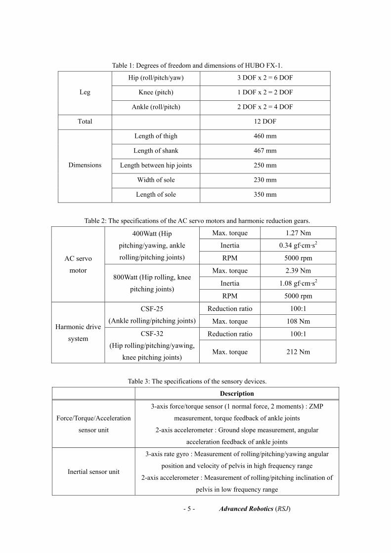
Table 1: Degrees of freedom and dimensions of HUBO FX-1.
Hip (roll/pitch/yaw) 3 DOF x 2 = 6 DOF
Knee (pitch) 1 DOF x 2 = 2 DOF Leg
Ankle (roll/pitch) 2 DOF x 2 = 4 DOF
Total 12 DOF
Length of thigh 460 mm
Length of shank 467 mm
Length between hip joints 250 mm
Width of sole 230 mm
Dimensions
Length of sole 350 mm
Table 2: The specifications of the AC servo motors and harmonic reduction gears.
Max. torque 1.27 Nm
Inertia 0.34 gf·cm·s2 400Watt (Hip
pitching/yawing, ankle rolling/pitching joints) RPM 5000 rpm
Max. torque 2.39 Nm
Inertia 1.08 gf·cm·s2
AC servo motor
800Watt (Hip rolling, knee pitching joints)
RPM 5000 rpm
Reduction ratio 100:1 CSF-25 (Ankle rolling/pitching joints) Max. torque 108 Nm
Reduction ratio 100:1 Harmonic drive
system CSF-32
(Hip rolling/pitching/yawing, knee pitching joints)
Max. torque 212 Nm
Table 3: The specifications of the sensory devices.
Description
Force/Torque/Acceleration
sensor unit
3-axis force/torque sensor (1 normal force, 2 moments) : ZMP
measurement, torque feedback of ankle joints
2-axis accelerometer : Ground slope measurement, angular
acceleration feedback of ankle joints
Inertial sensor unit
3-axis rate gyro : Measurement of rolling/pitching/yawing angular
position and velocity of pelvis in high frequency range
2-axis accelerometer : Measurement of rolling/pitching inclination of
pelvis in low frequency range

- 6 - Advanced Robotics (RSJ)
3. VIBRATION MODES OF HUBO FX-1 DURING WALKING
As the body frames of HUBO FX-1 are not sufficiently stiff, two types of large structural vibrations
are generated during walking. One is the vibration of the swinging leg, and the other is the vibration
of the torso with respect to the hip joint of the supporting leg. It is important to note that the dynamics
of the second vibration mode is dependent to the weight of the passenger, while that of the first
vibration mode are not. These vibration modes have a detrimental effect on the walking stability and
the comfort passenger. Hence, it is essential for HUBO FX-1 to reduce the vibrations while walking.
3.1. The First Mode Vibration : rolling/pitching vibrations of the swinging leg
When the biped robot is walking, it is easy to observe the shaking of the swinging leg. This structural
vibration is usually generated due to the hard position control of the joints and flexible frames that
connect the leg to the pelvis. Fig. 2 shows schematics of this first mode vibration. The swinging leg is
oscillating in rolling and pitching directions during the single support phase. The vibration negatively
influences the walking stability, as the swinging foot cannot accurately land on the desired point of the
ground. Actually, it was observed that the landing position error is approximately ± 5 ~ 10 mm.
Furthermore, the swinging foot may collide with the supporting leg, and the data of the force/torque
sensor thus becomes contaminated with noise.
Figure 2: Schematics of the first mode vibration.
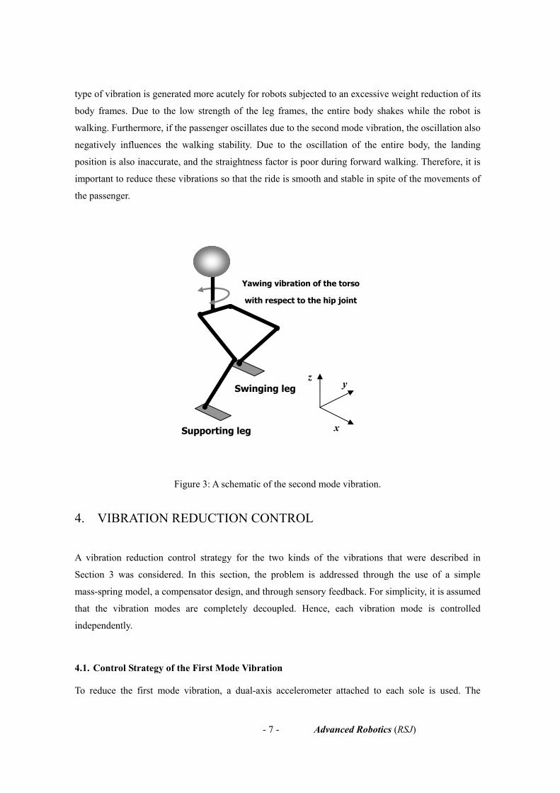
3.2. The Second Mode Vibration : yawing vibration of torso
The second mode vibration is caused by the torsional bending of the supporting leg in the single
support phase. More specifically, the upper body oscillates in the yaw direction with respect to the hip
joint of the supporting leg. A schematic of the second mode vibration is represented in Fig. 3. This
Coronal Plane View Sagittal Plane View
Rolling
VibrationPitching
Vibration
Swinging
leg
Supporting
leg
Swinging
leg
Supporting
leg
- 7 - Advanced Robotics (RSJ)
type of vibration is generated more acutely for robots subjected to an excessive weight reduction of its
body frames. Due to the low strength of the leg frames, the entire body shakes while the robot is
walking. Furthermore, if the passenger oscillates due to the second mode vibration, the oscillation also
negatively influences the walking stability. Due to the oscillation of the entire body, the landing
position is also inaccurate, and the straightness factor is poor during forward walking. Therefore, it is
important to reduce these vibrations so that the ride is smooth and stable in spite of the movements of
the passenger.
Figure 3: A schematic of the second mode vibration.
4. VIBRATION REDUCTION CONTROL
A vibration reduction control strategy for the two kinds of the vibrations that were described in
Section 3 was considered. In this section, the problem is addressed through the use of a simple
mass-spring model, a compensator design, and through sensory feedback. For simplicity, it is assumed
that the vibration modes are completely decoupled. Hence, each vibration mode is controlled
independently.
4.1. Control Strategy of the First Mode Vibration
To reduce the first mode vibration, a dual-axis accelerometer attached to each sole is used. The
Supporting leg
Swinging leg
Yawing vibration of the torso
with respect to the hip joint
z
x
y
- 8 - Advanced Robotics (RSJ)
advantages of the accelerometer are that it can measure both the inclination of the ground during the
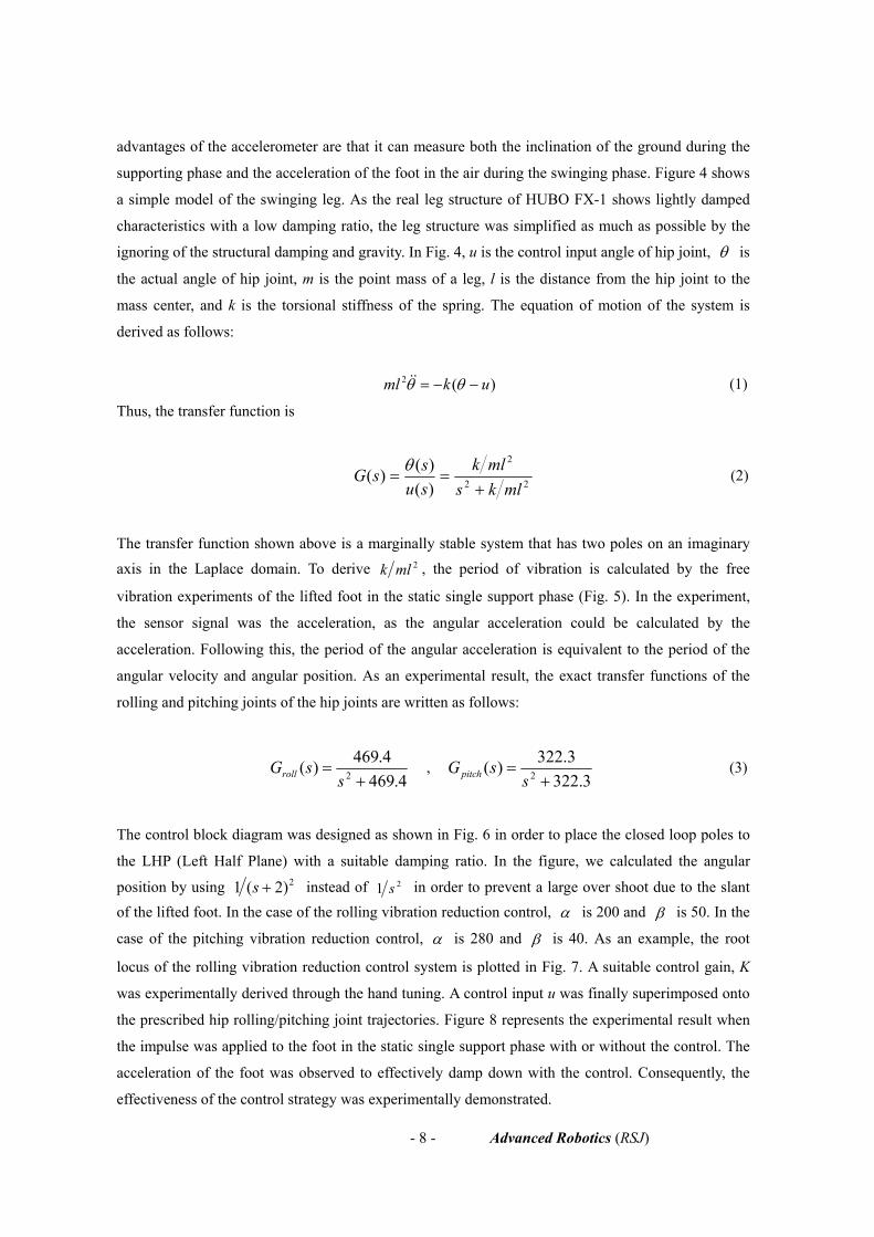
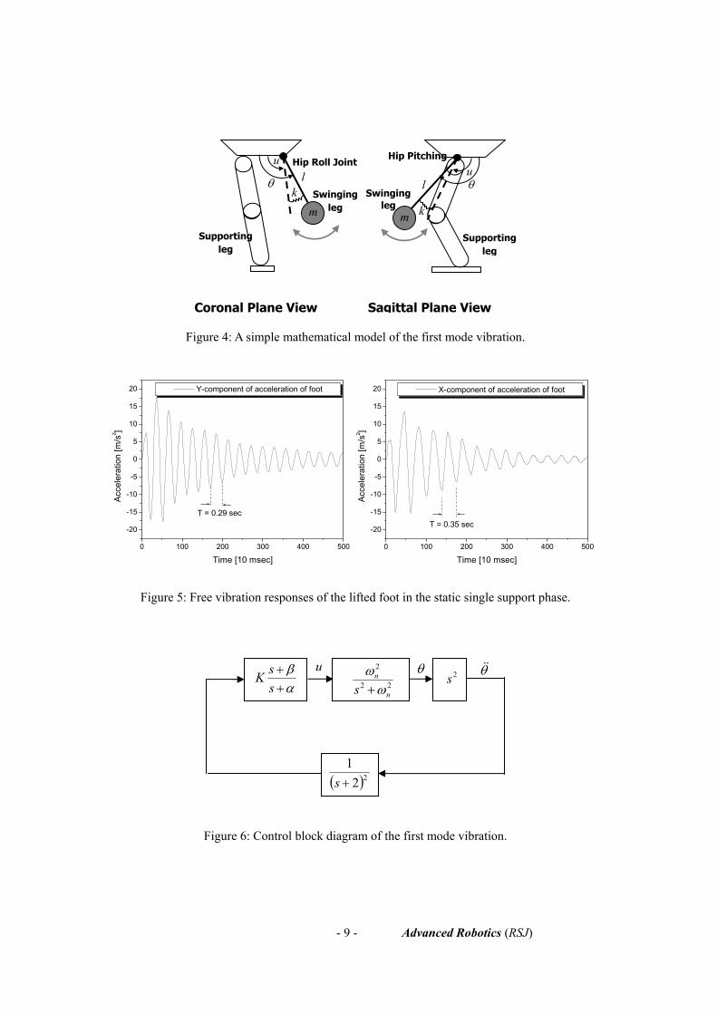
supporting phase and the acceleration of the foot in the air during the swinging phase. Figure 4 shows
a simple model of the swinging leg. As the real leg structure of HUBO FX-1 shows lightly damped
characteristics with a low damping ratio, the leg structure was simplified as much as possible by the
ignoring of the structural damping and gravity. In Fig. 4, u is the control input angle of hip joint, θ is
the actual angle of hip joint, m is the point mass of a leg, l is the distance from the hip joint to the
mass center, and k is the torsional stiffness of the spring. The equation of motion of the system is
derived as follows:
)(2 ukml −−= θθ&& (1)
Thus, the transfer function is
22
2
)()()(
mlksmlk
sussG
+==
θ (2)
The transfer function shown above is a marginally stable system that has two poles on an imaginary
axis in the Laplace domain. To derive 2mlk , the period of vibration is calculated by the free
vibration experiments of the lifted foot in the static single support phase (Fig. 5). In the experiment,
the sensor signal was the acceleration, as the angular acceleration could be calculated by the
acceleration. Following this, the period of the angular acceleration is equivalent to the period of the
angular velocity and angular position. As an experimental result, the exact transfer functions of the
rolling and pitching joints of the hip joints are written as follows:
4.469
4.469)( 2 +=
ssGroll ,
3322.322.3)( 2 +
=s
sGpitch (3)
The control block diagram was designed as shown in Fig. 6 in order to place the closed loop poles to
the LHP (Left Half Plane) with a suitable damping ratio. In the figure, we calculated the angular
position by using 2)2(1 +s instead of 21 s in order to prevent a large over shoot due to the slant of the lifted foot. In the case of the rolling vibration reduction control, α is 200 and β is 50. In the
case of the pitching vibration reduction control, α is 280 and β is 40. As an example, the root
locus of the rolling vibration reduction control system is plotted in Fig. 7. A suitable control gain, K
was experimentally derived through the hand tuning. A control input u was finally superimposed onto
the prescribed hip rolling/pitching joint trajectories. Figure 8 represents the experimental result when
the impulse was applied to the foot in the static single support phase with or without the control. The
acceleration of the foot was observed to effectively damp down with the control. Consequently, the
effectiveness of the control strategy was experimentally demonstrated.
- 9 - Advanced Robotics (RSJ)
Figure 4: A simple mathematical model of the first mode vibration.
0 100 200 300 400 500
-20
-15
-10
-5
0
5
10
15
20
0 100 200 300 400 500
-20
-15
-10
-5
0
5
10
15
20
T = 0.35 secT = 0.29 sec
Acc
eler
atio
n [m
/s2 ]
Time [10 msec]
Y-component of acceleration of foot
Acc
eler
atio
n [m
/s2 ]
Time [10 msec]
X-component of acceleration of foot
Figure 5: Free vibration responses of the lifted foot in the static single support phase.
Figure 6: Control block diagram of the first mode vibration.
Coronal Plane View Sagittal Plane View
u
mk
m k
uθ θl l
Hip Roll Joint
Supporting leg
Swinging leg
Swinging leg
Hip Pitching
22
2
n
n
s ωω+α
β++
ssK 2s
θ θ&&
( )221+s
u
Supporting leg

- 10 - Advanced Robotics (RSJ)
Figure 7: Root locus plot of rolling vibration reduction control.
0 100 200 300 400 500
-20
-15
-10
-5
0
5
10
15
20
0 100 200 300 400 500
-20
-15
-10
-5
0
5
10
15
20
Acce
lera
tion
[m/s
2 ]
Time [10 msec]
Y-comp. of foot acceleration without control Y-comp. of foot acceleration with control
Acce
lera
tion
[m/s
2 ]
Time [10 msec]
X-comp. of foot acceleration without control X-comp. of foot acceleration with control
Figure 8: Free vibration responses of the lifted foot with or without control
in the static single support phase.
4.2. Control Strategy of the Second Mode Vibration
To reduce the second mode vibration, a rate gyro sensor was utilized, which measures the angular
velocity. As the torso oscillates in the z-direction (yaw direction) with respect to the hip joint of the
supporting leg, the rate gyro was attached to the pelvis center to measure the yaw angular position for
the feedback control. Figure 9 shows a simple model of the second mode vibration, which is identical
to the mass-spring model in Section 4.1. The pelvis and the swinging leg was also assumed to be a
mass-spring model as it acts like a lightly damped system with a small damping ratio. In Fig. 8, u is
the control input angle of the hip yawing joint, θ is the actual angle of the hip yawing joint, m is the
point mass of the pelvis, the lifted leg, and the passenger, l is the distance between the hip joint and

- 11 - Advanced Robotics (RSJ)
the mass center, and k is the torsional stiffness of the spring.
The equation of motion is identical to (1). In the same manner, the transfer function was derived by
calculating the period of vibration from the experiments (Fig. 10). It is important to note that the
equivalent mass varies according to the weight of the passenger. As the weight of each passenger is
different, the dynamic characteristics of the system also vary. However, at this moment, a constant
mass was used first, thus the weight of the passenger is always 81 kg. This is assumed as the weight of
a normal adult is approximately 81 kg. Variable mass will be considered as a future work. As an
experimental result, the transfer function was derived as follows:
74.246
74.246)()()( 2 +==
ssussGyaw
θ (4)
In the above system, a lead compensator was added, thus a control block diagram was designed as
shown in Fig. 11. In this diagram, a high pass filter was used for cutting off the low-frequency sensor
drift. The angular position was calculated by integrating the filtered signal with respect to time. In the design of the lead compensator, α is 280 and β is 40. The root locus of this feedback control
system is plotted in Fig. 12. The control gain K was tuned experimentally. The control input u is
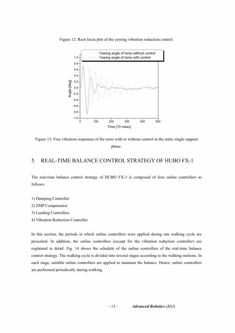
superimposed on the prescribed hip yawing trajectory of the supporting leg. Fig. 13 shows
experimental result when a disturbance was applied to the body in the static single support phase. It is
clear that the yawing vibration of the torso was damped down with a higher damping ratio.
Consequently, it is shown that the control strategy is effective for reducing the yawing vibration of the
torso.
m
Ankle
Knee
Hip Yawing Joint
x y
z
Yaw
Roll Pitch
k uθSupporting
Leg l

- 12 - Advanced Robotics (RSJ)
Figure 9: Simple model of the second mode vibration.
0 100 200 300 400 500-1.0
-0.8
-0.6
-0.4
-0.2
0.0
0.2
0.4
0.6
0.8
1.0
T = 0.4 sec
Ang
le [d
eg]
Time [10 mesc]
Yawing angle of torso
Figure 10: Free vibration response of the torso in the static single support phase.
Figure 11: Control block diagram of the second mode vibration.
22
2
n
n
s ωω+α
β++
ssK sθ θ&u
628.0+ss
High Pass Filter
s1
- 13 - Advanced Robotics (RSJ)
Figure 12: Root locus plot of the yawing vibration reduction control.
0 100 200 300 400 500-1.0
-0.8
-0.6
-0.4
-0.2
0.0
0.2
0.4
0.6
0.8
1.0
Ang
le [d
eg]
Time [10 mesc]
Yawing angle of torso without control Yawing angle of torso with control
Figure 13: Free vibration responses of the torso with or without control in the static single support
phase.
5. REAL-TIME BALANCE CONTROL STRATEGY OF HUBO FX-1
The real-time balance control strategy of HUBO FX-1 is composed of four online controllers as
follows:
1) Damping Controller
2) ZMP Compensator
3) Landing Controllers
4) Vibration Reduction Controller
In this section, the periods in which online controllers were applied during one walking cycle are
presented. In addition, the online controllers (except for the vibration reduction controller) are
explained in detail. Fig. 14 shows the schedule of the online controllers of the real-time balance
control strategy. The walking cycle is divided into several stages according to the walking motions. In
each stage, suitable online controllers are applied to maintain the balance. Hence, online controllers
are performed periodically during walking.

- 14 - Advanced Robotics (RSJ)
Figure 14: The schedule of the online controllers of the real-time balance control strategy.
5.1. Damping Control
The damping controller was designed to eliminate the sustained oscillation of the torso caused by the
force/torque sensors installed at the ankle joints in the single support phase [8]. As the strain gages are
used to measure the forces and torques, the sensor structure is compliant. Therefore, the robot is
oscillating with respect to the ankle joint. To damp down this oscillation, the robot was modeled as an
inverted pendulum with a compliant joint and the damping controller was designed to impose the
damping forces at the ankle joints without change of steady state value. Figure 15 and 16 show the
mathematical modeling and the control block diagram respectively. In Fig. 15, l is the distance from
the ground to the center of the mass, m is the total point mass, u is the reference joint angle, θ is the
actual joint angle due to the compliance, K is the stiffness of the leg, T is the measured torque, and g is
the gravitational acceleration. In Fig. 16, α is lgmlK −2 , β is 2mlK , kd is the damping
control gain and uc is the compensated joint angle. The equation of motion (5) and the damping
control law (6) are as follows:
)(2 uKmlmglT −=−= θθθ && (5)
θ̂&dc kuu −= (6)
left leg
right leg
SSP DSP SSP DSP SSP SSP
Damping Controller ZMP Compensator
Landing Controllers
Vibration Reduction Controller
Vibration Reduction Controller
Damping Controller ZMP Compensator
Landing Controllers
One Walking Cycle
Max. altitude of left foot
Max. altitude of right foot

- 15 - Advanced Robotics (RSJ)
Figure 15: Inverted pendulum model with compliant joint in the single support phase.
Figure 16: Block diagram of the damping control.
5.2. ZMP Compensator
The ZMP compensator was designed in the single support phase as the damping controller alone
would not suffice to maintain stable walking [9]. Equation (7) shows the ZMP dynamics of the simple
inverted pendulum model with a compliant joint. Here, Ypelvis is the lateral displacement of the pelvis, l
is the distance from the ground to the center of mass, g is the gravitational acceleration and YZMP is the
lateral ZMP. As the pelvis displacement and acceleration is related to the ZMP, it is desirable to
control simultaneously both the torso movement by the damping controller and the ZMP by the ZMP
compensator.
pelvispelvisZMP YglYY &&−= (7)
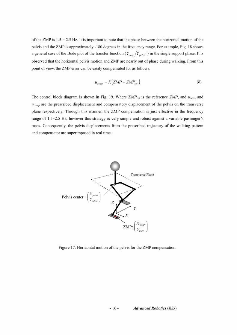
To compensate for the ZMP error, the pelvis displacement was used as the control input (Fig. 17).
That is, the X-component and Y-component of ZMP are compensated by moving the pelvis in forward
and lateral directions on the transverse plane. In previous research by the authors, the transfer
functions between the horizontal motion of the pelvis and ZMP were experimentally derived by
carrying out a frequency response analysis. Generally, when the robot is walking, the frequency range
dk observer
y T=2
2
( )sKs
β αα
− + −+
+
-
u
θ̂&
cu
K
u
θ
T
g m
l
- 16 - Advanced Robotics (RSJ)
of the ZMP is 1.5 ~ 2.5 Hz. It is important to note that the phase between the horizontal motion of the
pelvis and the ZMP is approximately -180 degrees in the frequency range. For example, Fig. 18 shows a general case of the Bode plot of the transfer function ( pelviszmp YY ) in the single support phase. It is
observed that the horizontal pelvis motion and ZMP are nearly out of phase during walking. From this
point of view, the ZMP error can be easily compensated for as follows:
( )refcomp ZMPZMPKu −= (8)
The control block diagram is shown in Fig. 19. Where ZMPref is the reference ZMP, and upelvis and
ucomp are the prescribed displacement and compensatory displacement of the pelvis on the transverse
plane respectively. Through this manner, the ZMP compensation is just effective in the frequency
range of 1.5~2.5 Hz, however this strategy is very simple and robust against a variable passenger’s
mass. Consequently, the pelvis displacements from the prescribed trajectory of the walking pattern
and compensator are superimposed in real time.
Figure 17: Horizontal motion of the pelvis for the ZMP compensation.
YZ
X
Pelvis center :
Transverse Plane
⎟⎟⎠
⎞⎜⎜⎝
⎛
pelvis
pelvis
YX
ZMP: ⎟⎟⎠
⎞⎜⎜⎝
⎛
ZMP
ZMP
YX

- 17 - Advanced Robotics (RSJ)
0.1 1 10-10
-5
0
5
10
15
20
25
30
0.1 1 10-360
-270
-180
-90
0
M
agni
tude
[dB
]
Frequency [rad/s]
Pha
se [d
eg]
Frequency [rad/s]
Figure 18: Experimental example of a Bode plot of the transfer function ( pelviszmp YY ) in the single
support phase.
Figure 19: ZMP compensation diagram.
5.3. Landing Controllers
The landing controllers are composed of the landing orientation controller and the landing shock
absorber. As for the landing orientation controller, it is designed for a smooth landing even if the
ground is inclined or the sole is inclined at the moment of contact with the ground. For a soft landing,
when the robot performs a heel-first landing, as shown in Fig. 20, the ankle joint moves as if the
spring-damper system is installed. In this case, the mass of the sole is neglected. By using the torque
feedback of the force/torque sensor, the control input of the landing orientation control is
superimposed on the prescribed ankle trajectory, as in (9).
KCssTuuc +
+=)(
(9)
ZMP)(sGpelvisu
-
+ compu
K
+
+refZMP

- 18 - Advanced Robotics (RSJ)
Here, T is the measured torque, C is the damping coefficient, K is the stiffness, u is the reference ankle angle and cu is the compensated reference ankle angle.
Figure 20: The schematics of the landing orientation control.
Next, the landing shock absorber that reduces the vertical shock was designed. The control method is
identical to that of the landing orientation control; however, a normal force is used as a feedback data
instead of the torque. Fig. 21 shows the schematics of the landing shock absorber. A virtual
spring-damper system is installed between the hip joint and ankle joint so that the vertical shock at the
moment of landing can be absorbed through a rapid modification of the height of the hip joint.
Equation (10) represents the control input of the landing shock absorber, which is superimposed on
the prescribed height of the hip joint.
kcsmssFzz z
c +++= 2
)( (10)
Here, zF is the measured normal force, c is the damping coefficient, k is the stiffness, z is the
reference pelvis height, cz is the compensated reference pelvis height and m is the equivalent mass.
Figure 21: The schematics of the landing shock absorber.
T
Landing orientation control C
CK
K
Sagittal plane view
m
Virtual Shock Absorberc kcz
zF
- 19 - Advanced Robotics (RSJ)
6. BIPED WALKING EXPERIMENT WITH A PASSENGER
In this section, the dynamic walking experiments of HUBO FX-1 are described. In the experiments, a
mass of 81 kg was loaded onto the robot in order to make the case that an adult person may ride the
robot. The walking experiments were performed on the ordinary room floor. Figure 22 shows the
prescribed forward walking pattern. The design parameters of the walking pattern are defined in Table.
4. First, to verify the effectiveness of the damping controller, the angular velocity of the pelvis with or
without the damping controller was measured. In Fig. 23, when the damping control was applied to
the ankle joint, the range of the angular velocity was reduced. In particular, the rolling angular
velocity was more diminished than the pitching angular velocity. On average, the rolling angular
velocity was reduced by 30%. This is because the lateral sinusoidal motion of the pelvis moves much
more dynamically than the forward motion of the pelvis, thus the pitching motion of the pelvis is
fundamentally stable. However, when the robot becomes unstable in the pitching direction, the robot
can tip over suddenly unless the damping control is applied.
Secondly, to verify the effectiveness of the ZMP compensator, the ZMP was plotted in Fig. 24 by
the force/torque sensor with or without the ZMP compensator. When the ZMP compensation was
applied, it was observed that the ZMP error was somewhat reduced. In other words, a horizontal
pelvis motion using a simple proportional negative feedback control was effective for the
compensation of the ZMP. Of course, initially, a well designed walking pattern is fundamentally
needed to generate suitable ZMP trajectory, but this simple ZMP compensation method is sufficient to
reduce the ZMP errors caused by the swinging of the passenger, vibrations of the body frames and
unevenness of the ground.
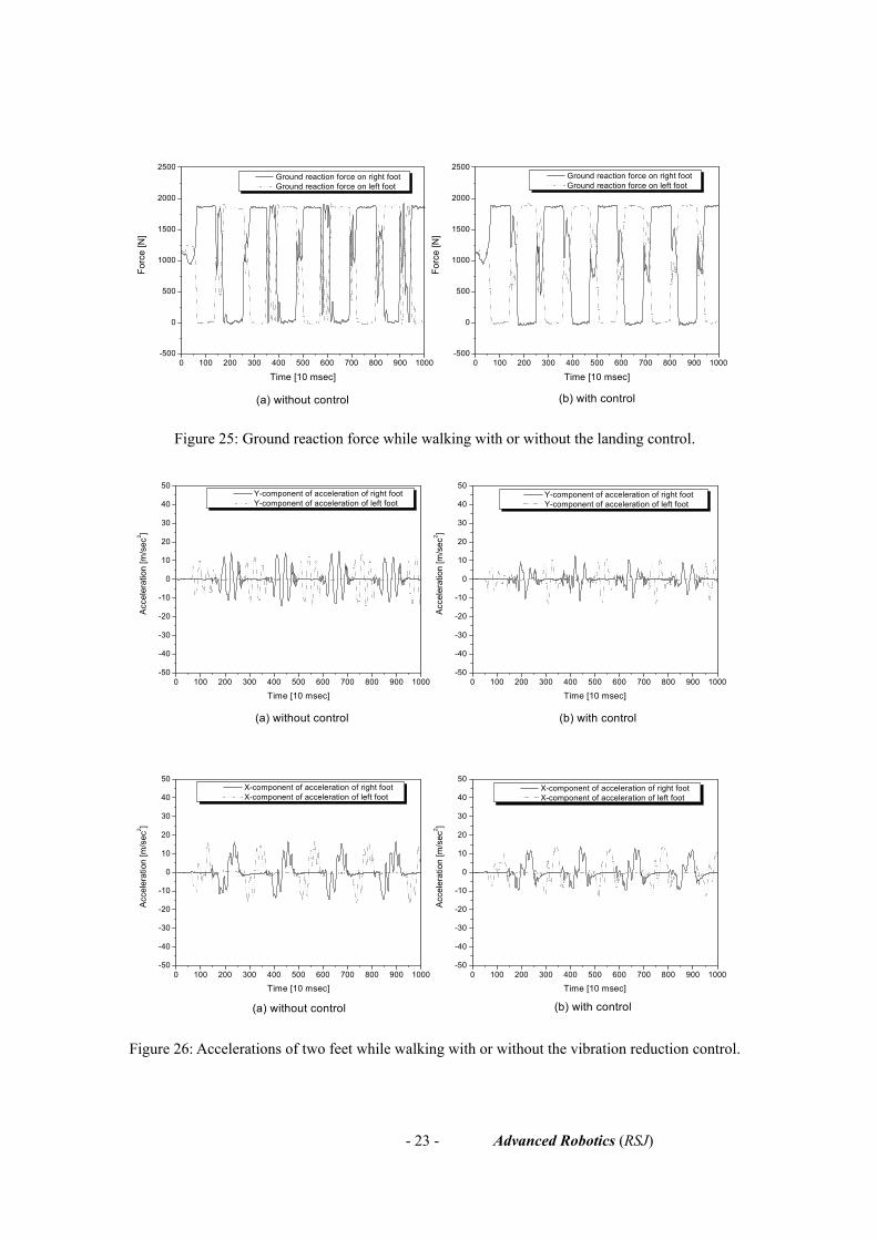
Thirdly, to verify the effectiveness of the landing controllers, the ground reaction forces of the soles
were represented with or without the landing controllers, as shown in Fig. 25. It was found that the
landing was more stable when the landing controllers were applied considering the small rate of
change in the forces.
Finally, the accelerations of two feet and the angular velocity of the pelvis were measured during
forward walking in order to verify the effectiveness of the vibration reduction controller. In Fig. 26, it
is observed that the amplitudes of the accelerations of two feet were reduced by about thirty percent.
In addition, in Fig. 27, the amplitude of the yawing angular velocity was not reduced at all. However,
the rate of change of angular velocity was reduced much.
Through these experiments, the real-time balance control strategy of HUBO FX-1 was shown to be
effective. Figure 28 shows a snapshot of the forward walking motion of HUBO FX-1 loading the
passenger. A dynamic biped walking movie of HUBO FX-1 can be seen on the web site
(http://www.hubolab.com).

- 20 - Advanced Robotics (RSJ)
Table 4: The design parameters of the forward walking pattern.
Description Value
Apelvis Lateral swing amplitude of pelvis 110 (mm)
Hfoot Maximum elevation of foot 40 (mm)
Lstep Step length (stride/2) 250 (mm)
Tstride Walking period (stride time) 2.2 (seconds)
Tstep Step time 1.1 (seconds)
Tdelay Delay time 0.11 (second)
dspκ Double support ratio 0.05 (5 %)
Tssp Single support time )0.1( dspstepT κ−×
Tdsp Double support time dspstepT κ×

- 21 - Advanced Robotics (RSJ)
0 100 200 300 400 500-100
-80
-60
-40
-20
0
20
40
60
80
100
0 100 200 300 400 500-250
0
250
500
750
1000
1250
Tdsp
Tssp
Hfoot
TdelayTstride
Tstep
Dis
plac
emen
t [m
m]
Time [10msec]
Pelvis displacement in Y direction Right foot displacement in Z direction Left foot displacement in Z direction
Apelvis
Dis
plac
emen
t [m
m]
Time [10msec]
Pelvis displacement in X direction Right foot displacement in X direction Left foot displacement in X direction
Lstep
Figure 22: The forward walking pattern.

- 22 - Advanced Robotics (RSJ)
-15 -10 -5 0 5 10 15-10
-5
0
5
10
15
20
-15 -10 -5 0 5 10 15-10
-5
0
5
10
15
20
Pitc
hing
Ang
ular
Vel
ocity
,ωp [d
eg/s
ec]
Rolling Angular Velocity,ωr [deg/sec]
(b) With Damping Control
Pitc
hing
Ang
ular
Vel
ocity
,ωp [d
eg/s
ec]
Rolling Angular Velocity,ωr [deg/sec]
(a) Without Damping Control
Figure 23: Angular velocity of the pelvis while walking with or without the damping control.
0 100 200 300 400 500 600 700 800 900 1000-300
-250
-200
-150
-100
-50
0
50
100
150
200
250
300
0 100 200 300 400 500 600 700 800 900 1000-300
-250
-200
-150
-100
-50
0
50
100
150
200
250
300
Dis
plac
emen
t [m
m]
Time [10 msec]
YZMP Reference YZMP
(b) with control
Dis
plac
emen
t [m
m]
Time [10 msec]
YZMP Reference YZMP
(a) without control
0 100 200 300 400 500 600 700 800 900 1000-500
0
500
1000
1500
2000
2500
0 100 200 300 400 500 600 700 800 900 1000-500
0
500
1000
1500
2000
2500
(d) with control(c) without control
Dis
plac
emen
t [m
m]
Time [10 msec]
XZMP
Reference XZMP
Dis
plac
emen
t [m
m]
Time [10 msec]
XZMP
Reference XZMP
Figure 24: ZMP while walking with or without ZMP compensation.
- 23 - Advanced Robotics (RSJ)
0 100 200 300 400 500 600 700 800 900 1000-500
0
500
1000
1500
2000
2500
0 100 200 300 400 500 600 700 800 900 1000-500
0
500
1000
1500
2000
2500
(b) with control
Forc
e [N
]
Time [10 msec]
Ground reaction force on right foot Ground reaction force on left foot
(a) without control
Forc
e [N
]
Time [10 msec]
Ground reaction force on right foot Ground reaction force on left foot
Figure 25: Ground reaction force while walking with or without the landing control.
0 100 200 300 400 500 600 700 800 900 1000-50
-40
-30
-20
-10
0
10
20
30
40
50
0 100 200 300 400 500 600 700 800 900 1000-50
-40
-30
-20
-10
0
10
20
30
40
50
(b) with control
Acc
eler
atio
n [m
/sec
2 ]
Time [10 msec]
Y-component of acceleration of right foot Y-component of acceleration of left foot
(a) without control
Acc
eler
atio
n [m
/sec
2 ]
Time [10 msec]
Y-component of acceleration of right foot Y-component of acceleration of left foot
0 100 200 300 400 500 600 700 800 900 1000-50
-40
-30
-20
-10
0
10
20
30
40
50
0 100 200 300 400 500 600 700 800 900 1000-50
-40
-30
-20
-10
0
10
20
30
40
50
(b) with control
Acc
eler
atio
n [m
/sec
2 ]
Time [10 msec]
X-component of acceleration of right foot X-component of acceleration of left foot
(a) without control
Acc
eler
atio
n [m
/sec
2 ]
Time [10 msec]
X-component of acceleration of right foot X-component of acceleration of left foot
Figure 26: Accelerations of two feet while walking with or without the vibration reduction control.

- 24 - Advanced Robotics (RSJ)
0 100 200 300 400 500 600 700 800 900 1000-30
-20
-10
0
10
20
30
0 100 200 300 400 500 600 700 800 900 1000-30
-20
-10
0
10
20
30
Angu
lar v
eloc
ity [d
eg/s
ec]
Time [10 msec]
Yawing Angular velocity of pelvis
(b) with control(a) without control
Angu
lar v
eloc
ity [d
eg/s
ec]
Time [10 msec]
Yawing Angular velocity of pelvis
Figure 27: Yawing angular velocity of the pelvis while walking with or without the vibration
reduction control.
Figure 28: Snapshot of the forward walking motion of HUBO FX-1 loading the passenger.
7. CONCLUSION AND FUTURE WORK
This paper described the experimental realization of dynamic walking for the human-riding biped
robot, HUBO FX-1. The most important feature of a human-riding robot is a practical application. A
person directly controls the robot without the need for intelligence by the robot, and the robot may
possibly be utilized as a medical robot, military robot or lifesaving robot or may serve other function.
Moreover, to perform the above practicalities effectively, the robot should be able to carry a heavy
person and work for a long time. Therefore, a weight reduction is essential for this human-riding robot.
The size and the thickness of the body frames were specifically reduced in order to increase the
payload capacity. Unfortunately, HUBO FX-1 was not able to walk stably due to the strong structural
vibrations caused by the weak body frames. The body structure was reinforced with aluminum bars,
but this was not effective. Eventually, these structural vibrations were reduced through a sensory
feedback control. The vibrations were found to have two modes, and the robot was modeled as a

- 25 - Advanced Robotics (RSJ)
simple spring-mass system. A vibration reduction controller was designed using a lead compensator
and the vibrations were experimentally reduced through the use of sensory feedback. As a walking
control algorithm, a real-time balance control strategy composed of a damping controller, a ZMP
compensator, landing controllers and a vibration reduction controller was applied to HUBO FX-1. The
real-time balance control strategy is a fundamentally switching control method based on real-time
sensory feedback. That is, in every walking cycle, online controllers are applied separately and in
sequence. Eventually, the control inputs of the online controllers are superimposed on a prescribed
walking pattern in real time. The performances of the online controllers were verified by a walking
experiment on a normal room floor of HUBO FX-1 which was loaded with a mass of 81 kg. Therefore,
the real-time balance control strategy was demonstrated.
As for future work, it is necessary to design the online controllers considering the variable mass and
consider a robot that uses internal batteries. Furthermore, two control strategies will be added to the
current walking control algorithm. One is an online walking pattern control strategy, which adapts the
robot to the ground condition and consumes only a minimum amount of energy while walking, thus
this may lead to longer battery life for the internal batteries. The other is a predicted motion control
strategy, which anticipates the future walking stability in order to prevent unworkable walking
situations. At present, the maximum step length is limited to 350 mm in consideration of the walking
stability. However, the maximum step length will be over 500 mm through the future work.
Acknowledgements This research was supported by MOCIE (Ministry of Commerce, Industry and Energy) of Republic of
Korea.
REFERENCES
[1] Y. Sakagami, R. Watanabe, C. Aoyama, S. Matsunaga, N. Higaki, and K. Fujimura, The
Intelligent ASIMO: System Overview and Integration, in Proc. IEEE/RSJ Int. Conf. on
Intelligent Robots and Systems, pp. 2478-2483 (2002)
[2] T. Ishida, Development of a Small Biped Entertainment Robot QRIO, in Proc. Int. Symp. on
Micro-Nanomechatronics and Human Science, pp. 23-28 (2004)
[3] Y. Ogura, H. Aikawa, H. Lim, and A. Takanishi, Development of a Human-like Walking Robot
Having Two 7-DOF Legs and a 2-DOF Waist, in Proc. IEEE Int. Conf. on Robotics & Automation,
pp. 134-139 (2004)
[4] K. Nishiwaki, T. Sugihara, S. Kagami, F. Kanehiro, M. Inaba, and H. Inoue, Design and
- 26 - Advanced Robotics (RSJ)
Development of Research Platform for Perception-Action Integration in Humanoid Robot: H6, in
Proc. IEEE/RJS Int. Conf. on Intelligent Robots and Systems, pp.1559-1564 (2000)
[5] S. Kagami, K. Nishiwaki, J. J. Kuffner Jr., Y. Kuniyoshi, M. Inaba, and H. Inoue, Online 3D
Vision, Motion Planning and Biped Locomotion Control Coupling System of Humanoid Robot :
H7, in Proc. IEEE/RSJ Int. Conf. on Intelligent Robots and Systems, pp. 2557-2562 (2002)
[6] S. Kajita, F. Kanehiro, K Kaneko, K Fujiwara, K Harada, K Yokoi, and H. Hirukawa, Biped
Walking Pattern Generation by using Preview Control of Zero-Moment Point, in Proc. IEEE Int
Conf. on Robotics & Automation, pp. 1620-1626 (2003)
[7] K. Akachi, K. Kaneko, N. Kanehiro, S. Ota, G. Miyamori, M. Hirata, S. Kajita, and F. Kanehiro,
Development of Humanoid Robot HRP-3P, in Proc. IEEE/RAS Int. Conf. on Humanoid Robots,
pp. 50-55 (2005)
[8] J. H. Kim and J. H. Oh, Realization of Dynamic Walking for the Humanoid Robot Platform
KHR-1, Advanced Robotics, Vol. 18, No. 7, pp. 749-768 (2004)
[9] J. Y. Kim, I. W. Park, and J. H. Oh, Experimental Realization of Dynamic Walking of Biped
Humanoid Robot KHR-2 using ZMP Feedback and Inertial Measurement, Advanced Robotics,
Vol. 20, No. 6, pp.707-736 (2006)
[10] I. W. Park, J. Y. Kim, J. Lee, and J. H. Oh, Mechanical Design of Humanoid Robot Platform
KHR-3(KAIST Humanoid Robot-3 : HUBO), in Proc. IEEE/RAS Int. Conf. on Humanoid Robots,
pp. 321-326 (2005)
[11] Y. Sugahara, H. Lim, T. Hosobata, Y. Mikuriya, H. Sunazuka, A. Takanishi, Realization of
Dynamic Human-Carrying Walking by a Biped Locomotor. Proc. IEEE Int. Conf. on Robotics &
Automation, pp.3055-3060 (2004)