experimental studies on hypersonic stagnation point ... educational notes/rto-en... · experimental...
TRANSCRIPT

RTO-EN-AVT-142 13 - 1
Experimental Studies on Hypersonic Stagnation Point Chemical Environment
O. Chazot VKI, 72 Chaussée de Waterloo
1640 Rhode-St-Genese Belgium
1 Introduction ............................................................................................................................................................................. 1 2 Stagnation point testing configuration..................................................................................................................................... 2
2.1 Methodology................................................................................................................................................................. 2 2.2 Ground testing facility .................................................................................................................................................. 4 2.3 Probes and measurements techniques ........................................................................................................................... 7 2.4 Numerical tools........................................................................................................................................................... 11 2.5 Hypersonic versus Subsonic testing............................................................................................................................ 12
3 Stagnation point reactor......................................................................................................................................................... 14 3.1 BL general definitions................................................................................................................................................. 14 3.2 Chemical environment evaluation............................................................................................................................... 16 3.3 Damköhler probes...................................................................................................................................................... 19
4 Application to the determination of TPS properties .............................................................................................................. 21 4.1 Emissivity determination ............................................................................................................................................ 21 4.2 Catalycity determination ............................................................................................................................................. 22 4.3 Reference catalycity determination............................................................................................................................. 24 4.4 The 0-model................................................................................................................................................................ 26
5 Conclusions ........................................................................................................................................................................... 27 6 Acknowledgements ............................................................................................................................................................... 28 7 References ............................................................................................................................................................................. 28
1 INTRODUCTION
Development of space transportation is a very challenging task for the aerospace research and industry. Hypersonic flight should be investigated in details to allow designing spacecraft according to the severe environment of their flight conditions. Typically during a planetary re-entry, when a capsule or a space vehicle approaches the relatively dense atmosphere a strong bow shock takes place ahead of the vehicle detached from its nose. It is subjected to wide range of pressure, heat transfer and shear levels. Several features, specific of hypersonic regime appear, as thin shock layer, entropy layer, viscous interaction … which are described in classical textbook [1-3]. Among those phenomena one could remark the high temperature effects since they appear as one of the critical points in the design phase of the vehicle mission. Indeed across the shock a large amount of kinetic energy is converted into thermal energy. This large energy density leads to high temperature of the gas mixture where dissociation and ionization take place. It results into a plasma flow which impinges on the vehicle wall. To sustain this important heat-transfer the spacecraft must be equipped with suitable Thermal Protection System (TPS). Their role is essential for the success of the re-entry manoeuvre, but their design is difficult due to the complexity of the heat-transfer phenomena. This later can be described with two main contributions [4]: a conductive heat-flux from the very high temperature flow reaching the wall, and a diffusion one due to chemical recombination at the wall activated by the catalytic properties of the TPS. The radiative part is left aside in this description, but one should remember that it could be important in certain condition.
From this situation it could be understood that ground testing appear as a strong requirement for TPS design. Number one they represent a first convenient step at reduce cost before the launch of a mission.
Chazot, O. (2007) Experimental Studies on Hypersonic Stagnation Point Chemical Environment. In Experiment, Modeling and Simulation of Gas-Surface Interactions for Reactive Flows in Hypersonic Flights (pp. 13-1 – 13-32). Educational Notes RTO-EN-AVT-142, Paper 13. Neuilly-sur-Seine, France: RTO. Available from: http://www.rto.nato.int/abstracts.asp.

Experimental Studies on Hypersonic Stagnation Point Chemical Environment
13 - 2 RTO-EN-AVT-142
Number two the tests allow a better control for the environment and for the measurement techniques to investigate TPS properties. However the development of high–enthalpy facilities for hypersonic testing is a challenge in itself. It involved the management of very high pressure levels to set-up extreme test conditions. Moreover, as it is known, a complete experimental simulation of hypersonic condition is most of the time impossible to achieve in a ground test facility [5]. If not all the conditions could be reproduced at once a lot of complementary facilities have been set-up. They are of several kinds to address at best these flight environments. They have been widely used to study the typical features of hypersonic flows and assess the critical issues associated with aerospace flight [6].
When the investigations concern high temperature effects, and their consequences on TPS material, specific ground facilities have to be used allowing long time range and chemical reacting flows. Classically plasma wind tunnel are used: Arc-jet facilities in which supersonic testing in different configuration is available at very high power [7] and very large scale [8], or Plasmatron facility offering usually a better chemical environment with subsonic testing [9,10]. This lectures focus on this last type of facility and attends to present the use of such plasma wind tunnel to study the chemical environment of a re-entry flight as well as the catalytic properties of TPS material. It will deal with the methodology adapted for the Plasmatron testing, some aspects of the facility design, the development of the specific measurement techniques and the data processing in connection with appropriate CFD tools. It will finally concentrate on the application of this ground testing methodology to the determination of TPS properties in real flight conditions.
2 STAGNATION POINT TESTING CONFIGURATION
2.1 Methodology In real flight condition the flow along the stagnation line present very different situations from the gas at rest in front of the shock up to the wall of the vehicle downstream. Across the bow shock the flow gain a large amount of thermal energy, it leads to high temperature and excites the different internal energy mode of the gas particles. Immediately after the shock appears a region of non-equilibrium flow. The excitation processes re-equilibrate downstream through a relaxation region and then reach an intermediate zone where Local Thermodynamic Equilibrium (LTE) can be consider in certain conditions. At the wall the flow enter the boundary layer area which can be mainly consider as a chemical non-equilibrium flow. This brief description is very schematic and does not pretend to give a complete view of all the processes occurring in reality. Figure 1 summarized this rough presentation. Many times the different regions overlap and it becomes much more complex. Classical textbook about gasdynamics must be consulted for more accurate details [11, 12].
Figure 1:real flight situation (stagnation line)

Experimental Studies on Hypersonic Stagnation Point Chemical Environment
RTO-EN-AVT-142 13 - 3
The reproduction of this kind of flow environment requires specific facilities. As it has been mentioned in the introduction the complete re-entry simulation, as it could interest the designer, is impossible or at best impratical in a laboratory. A classical similarity analysis as it used to be practiced in a wind tunnel cannot be carry out in this case. However the experimentalists can consider the problem in different parts and provide sufficient simulation for the study of various aspects of the re-entry flights. For instance, concerning the heat-transfer for the hypersonic stagnation point, an inspection of the Boundary Layer (BL) equation as it could be written in those conditions illustrate this situation. Considering the treatment of the compressible axisymmetric BL equations done by Lees [13] after Cohen and Reshotko [14] using the Howarth-Doronitzin transformation with Mangler transformation and η as similitude parameter, it can be read:
∫∞
=0
02dyr
sue ρη with ∫
∞
=0
20 dxrus eee ρµ (1)
(Only the final result is given here, the derivative of the function f corresponds to the non-dimensional longitudinal velocity, the function g corresponds to the non-dimensional temperature and z to a non-dimensional concentration.)
x-momentum: ( ) 02 2 =⎟⎠
⎞⎜⎝
⎛ ′−∂∂
+′′+′′′ fsu
usfffl ee
e ρρ (2)
total energy:
0)11(Pr
)Pr11(2
2Pr
2
=⎟⎟⎠
⎞⎜⎜⎝
⎛′−+
′⎟⎠⎞
⎜⎝⎛ ′′′−+⎟
⎠⎞
⎜⎝⎛ ′+′ ∑ ii
se
ie
se
e zhhc
LeLelffl
hglgf µ (3)
Atom mass conservation: 021
=⎟⎠⎞
⎜⎝⎛−
′⎟⎠⎞
⎜⎝⎛ ′+′
−
is
ie
cdxduz
Sclzf
ρω (4)
One can notice that these equations are not similar due to dimensional terms and extra terms accounting for diffusion and production rate. In some case, as the cold wall at equilibrium with some approximation the set of equations can be reduced to a similar one [13]. However in the general case, if the production term vanishes (ωi = 0) by considering equilibrium it appears that He, Pe and du/dx are the values that have to be reproduced at stagnation point to have identical situations from equations (2) and (3). In this condition it has been shown that a complete duplication of real flight condition is possible in ground facility, if the total enthalpy (He), the total pressure (Pe) and the velocity gradient (β = du/dx), of the flight conditions, can be matched locally on the test sample [4, 13-15]. Experiments based on this approach could be designed and the very first ground facility set up to study those aerothermodynamics effects was the shock tube [16]. It allows an accurate duplication of the flow for the stagnation location [15]. It is still used nowadays to study gas reaction rate in the hypervelocity conditions. Its simple principle allows a good control of the test environment. But like most of the others hypersonic ground facilities the test duration (1 ~ 100 ms) are too short to be suitable for TPS testing. These material tests require high enthalpies associated with long time scale (in this order of the material thermal inertia) to be representative of re-entry conditions. In this frame facilities like arcjet and Plasmatron have been developed [17]. They are able to produce dissociated flows for a long time base which is suitable for tests involving aero-thermochemistry. The tests are restricted to local area where the flight conditions could be reproduced. It concerns specifically the stagnation point. The complete theory of stagnation point heat transfer for dissociated flows have been elaborated for hypersonic boundary layers [4], the expression for equilibrium flow is given below (Le = 1):

Experimental Studies on Hypersonic Stagnation Point Chemical Environment
13 - 4 RTO-EN-AVT-142
( ) ( ) Pr//67.02/1
4.0w
ewwwwee hHe
dxduQw −⎟
⎠⎞
⎜⎝⎛= µρµρµρ (5)
The theory is well suited for hypersonic facilities and in the introduction of their paper Fay and Riddel [4] make a short remark about the relevance of boundary layer in re-entry problems. Indeed the hypothesis of the existence of a boundary layer should be preserved for the development of the theory. In the case of plasma facility where the analysis involving non-dimensional numbers as Mach and Reynolds can no longer be maintained this question had to be re-examined. In this purpose the theoretical frame has been adapted for plasma wind tunnel by Kolesnikov, in a methodology called Local Heat Transfer Simulation (LHTS) [18] and a very careful justification of this development is given in the PhD thesis of Barbante [19]. The duplication of the flight condition at stagnation point is strictly reduced to the boundary layer with its appropriate treatment. In the case of a subsonic plasma facility like the VKI Plasmatron [20] the testing configuration could be presented as in figure 2.
Figure 2 : Testing in Plasmatron facility in LHTS conditions
Knowing the total enthalpy Hs and the total pressure Ps, the extrapolation to the freestream flight conditions are achieved considering the conservation of enthalpy and momentum along the stagnation line [18, 21].
H∞ + ½. V∞ = Hs (6)
P∞ + ½. ρ∞V∞ = Ps (7)
2.2 Ground testing facility The knowledge of the working principles and the operating conditions of the ground facility used to carry out the experimental study is essential for the interpretation and a relevant discussion about the results obtained. This lecture presents developments achieved in the VKI Plasmatron and some details concerning this type of facility is given here.
A plasmatron is a plasma wind tunnel using an Inductively Coupled Plasma (ICP) torch as plasma source. ICP torches have been developed for 50 years, initially in Russia, in the context of electrical discharge in

Experimental Studies on Hypersonic Stagnation Point Chemical Environment
RTO-EN-AVT-142 13 - 5
low pressure gases [22]. These devices are used in spectroscopy , material processing, spray coating, powder synthesis, chemical vapor deposition and in many, generally called Thermal Plasma Processes (TPP) [23]. Their applications to high enthalpy wind tunnel are mainly due to their high purity and high energy density flow characteristics which are very beneficial for aerothermodynamic studies. The stagnation configuration of TPS testing with ICP torch is sketch in figure 3.
Figure 3 : Sketch of an ICP torch for TPS tests in a Plasmatron facility
The basic concept of ICP torches is also schematically shown in this figure (fig. 3). A coil with a few turns, connected to a high-frequency generator, surrounds a quartz tube, where gas is injected (argon, air, CO2). Once an initial ionization is created by suitable means, the coil induces eddy currents in the conducting gas, transferring energy and maintaining it into a plasma state.
The so-called “torch” is the chamber where the plasma discharge takes place. It is designed basically with two coaxial flows inside the quartz tube surrounded by the coil. The plasma region can be divided in two parts, the most sensitive part is the coil region called “the discharge region” where all the parameters interact strongly and the downstream part named the "plasma jet" (fig.3). Historically this design has been evolving during the last two decades, as a result of direct observation of the torch discharge and of its behavior [24-28]. For the same purpose, measurements of emission intensity of samples introduced into the plasma have been made. By these methods “empirical laws” have been established to match the minimum flow rate [26], the tube configuration [27], and critical geometrical parameters in an ICP torch [28]. All these criteria led to a torch design characterized by an easy ignition, a good stability and a low consumption of plasma gas. A correct axi-symmetry of the of the plasma jet is also of major importance for the stagnation point testing. This aspect has to be attentively checked and the torch properly designs to achieve good testing conditions [29]. Torch design is a very important point for a Plasmatron facility it could be investigate by careful experiments [30] joined with CFD computations [31].
The fundamental phenomenon occurring in an ICP torch is radiation/matter interaction. The plasma discharge is heated by electrical currents induced by a time varying magnetic field and fed by a gas flow. This leads to an interaction between the fluid flow field, the temperature field and the electromagnetic field in the discharge region. As shown in figure 4, each field directly interacts with the other two.

Experimental Studies on Hypersonic Stagnation Point Chemical Environment
13 - 6 RTO-EN-AVT-142
Figure 4 : Modes of interaction between the fluid flow field, the temperature field
and the electromagnetic field
The operation of an ICP torch can be described in a more practical way. Basically the discharge depends on two parameters: the magnetic field imposed by the current intensity and the coil design, and the flow field imposed by the gas mass flow rate and the injection system design. The temperature field appears as a result of the interaction of these two parameters.
Unsteadiness of the discharge is a more complex problem because of all the interconnected parameters. Nevertheless two main sources of unsteadiness can be distinguished: the electrical effects and the fluids dynamic effects. The electrical fluctuations due to the time varying electro-magnetic fields represent a very high frequency (1/f = τw ~ 10-6s) and can be average in comparison of the characteristic time of the flow (D/U = δt ~ 10-3s). However some interactions exist: the modulation of the current after the rectifier, in the power generator, is reflected in the energy deposition into the plasma discharge. This phenomenon occurs on a time base of the order of the flow time (τe ~ 10-3s). It could be reduced by adjusting the plasma setting. In addition to those phenomena one have to consider the influence of the confined recirculation zone in the ICP torch which induce a vortex shedding and creates unsteadiness traveling in the plasma flow [32].
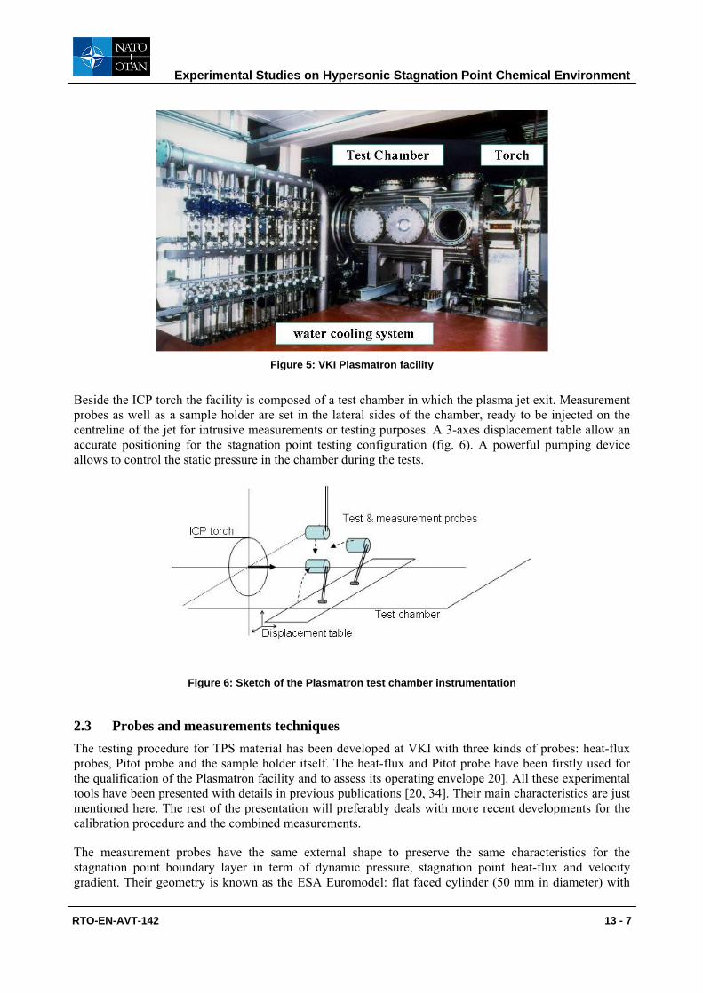
The plasma facility used at VKI for the testing is a Plasmatron-type using an Inductively Coupled Plasma (ICP) torch (fig. 5). Its basic working principle and operation, as well as the test configuration correspond to what has been presented above (fig. 3). The main control parameters are the mass flow injected into the torch, the pressure in the test chamber and the generator power imposed. In the context of TPS testing and catalycity determination it could be relevant to mention that it is an appropriate facility for those purposes: It allows testing in a subsonic plasma jet, where LTE conditions are more likely to be verified, produced by a ICP torch which provide chemical purity. This last point has been checked by spectroscopic measurements for the most powerful emission line of copper, silicon and iron [33].
Experimental Studies on Hypersonic Stagnation Point Chemical Environment
RTO-EN-AVT-142 13 - 7
Figure 5: VKI Plasmatron facility
Beside the ICP torch the facility is composed of a test chamber in which the plasma jet exit. Measurement probes as well as a sample holder are set in the lateral sides of the chamber, ready to be injected on the centreline of the jet for intrusive measurements or testing purposes. A 3-axes displacement table allow an accurate positioning for the stagnation point testing configuration (fig. 6). A powerful pumping device allows to control the static pressure in the chamber during the tests.
Figure 6: Sketch of the Plasmatron test chamber instrumentation
2.3 Probes and measurements techniques The testing procedure for TPS material has been developed at VKI with three kinds of probes: heat-flux probes, Pitot probe and the sample holder itself. The heat-flux and Pitot probe have been firstly used for the qualification of the Plasmatron facility and to assess its operating envelope 20]. All these experimental tools have been presented with details in previous publications [20, 34]. Their main characteristics are just mentioned here. The rest of the presentation will preferably deals with more recent developments for the calibration procedure and the combined measurements.
The measurement probes have the same external shape to preserve the same characteristics for the stagnation point boundary layer in term of dynamic pressure, stagnation point heat-flux and velocity gradient. Their geometry is known as the ESA Euromodel: flat faced cylinder (50 mm in diameter) with

Experimental Studies on Hypersonic Stagnation Point Chemical Environment
13 - 8 RTO-EN-AVT-142
rounded corners (10 mm radius) (fig. 7). The probes are water cooled and mounted on a foot to allow their injection in the plasma jet. A cylindrical channel along the centre of the probe body is available for the passage of the sensor device. At the front a sensing element of 14 mm in diameter is installed in the cylinder. It corresponds to a water cooled calorimeter for heat-flux measurement (fig. 7) or a water cooled pressure orifice for the total pressure measurement (fig. 8).
Figure 7: Sketch of the heat flux probe, with water-cooled calorimeter installed inside
Figure 8: Pitot probe mounted to 50mm diameter probe
The Sample holder is composed of two coaxial tubes in which water circulates for cooling. At the extremity, a SiC cover is attached to the holder body by three metallic pins. The sample to be tested is installed in this support, maintained at its periphery by the cover and at its back by an insulator (fig.9). The sample holder has the same shape as the stagnation point probes to preserve the similitude in the test conditions. The surface temperature is measured on the front part by a 2-colors pyrometer (λ1:0.75-1.1µm, λ2:0.95-1.1µm). The conductive heat flux passing through the TPS sample is measured at the back, after an insulating material, by a water-cooled calorimeter (fig. 9).

Experimental Studies on Hypersonic Stagnation Point Chemical Environment
RTO-EN-AVT-142 13 - 9
Figure 9: Sketch of the Sample Holder
Stagnation point heat-flux calibration for plasma flow is not trivial to realize since it is difficult to reproduce and control the thermal environment of the dissociated gas in a reference test bench. Several calibration benches, involving radiative heat-transfer, have been tested at VKI but the problems in determining the reference heat-flux were limitating to achieve accurate results [ref VKI reports]. They end-up in a never ending loop to reach a relevant calibration procedure. To come over those difficulties the method finally set-up at VKI proposes to compare in-situ the current measurement technique, using water cooled calorimeter with a reference one, using a slug calorimeter, following the designation of the American Society for Testing and Materials (ASTM) [35]. This procedure presents the advantage of direct measurements in the same environment and the same configuration that the calorimeter to calibrate. The calibration process requires careful and diligent experiments with an appropriated Data Acquisition System to allow high enough sampling rate. In parallel to those a data processing method have been set-up at VKI to exploit at best the transient measurements an evaluate the related losses. Only a schematic view of the Copper Slug installation used for the calibration in the VKI plasmatron is shown in figure 10, the complete study is reported in a VKI Technical Note [36]. The final accuracy for the current stagnation point heat-flux probe is found to be 7 %.
Figure 10: Schematic view of Copper Slug Calorimeter for heat-transfer calibration
A combined probe which permits to measure simultaneously heat-transfer and total pressure at stagnation point has been designed at VKI [37-39]. It is based on a classical measurement probe in which the water
Probe
Ice Bath BNC Connection
Type K Thermocouple
Plasma Jet
Special Tape
Teflon ring
Air Gap
Copper Slug

Experimental Studies on Hypersonic Stagnation Point Chemical Environment
13 - 10 RTO-EN-AVT-142
cooled calorimeter is equipped with a pressure line for total pressure evaluation (fig. 11). A test campaign has been carried out to assess its performance and to compare its measurement results with the classical heat-flux probe ones; good agreement has been found (fig. 12). The integration of the combined probe is a major advantage to determine the stagnation point characteristics in a single probe injection. This probe is permanently installed in the Plasmatron test chamber. It allows checking the testing conditions just before placing the test article into the plasma jet. This procedure avoids the problems link to repeatability issue and lead to a large improvement in the test accuracy.
Figure 11: Combined calorimeter
Figure 12: Heat-flux and Combined probe comparison

Experimental Studies on Hypersonic Stagnation Point Chemical Environment
RTO-EN-AVT-142 13 - 11
2.4 Numerical tools The methodology as presented in the first section, adapted to the experimental stagnation point configuration requires as well the use of CFD codes. It is usually presented as an hybrid methodology where experiments and CFD are intimately linked. If the facility allows to set up the boundary layer physically at the stagnation point, the CFD allows to describe it and determine its parameters with two main numerical codes:
1- The ICP code simulates the experimental configuration. It computes the flow in the ICP torch and around the sample in the test chamber. It solves the time averaged magneto-hydrodynamic equation at low Mach and low magnetic Reynolds number. In this computation local thermodynamic equilibrium and axisymmetric flow is assumed. It was developed by D. vanden Abeele [40] and T. Magin [41].
2- The BL code simulates the boundary layer that develops in the neighborough of the stagnation point. It solves the laminar chemically reacting boundary layer for axisymmetric or 2D flows. It was developed by P. Barbante [19].
These codes are interfaced with the Pegase library, written at VKI [42], which performs the computation of thermodynamic and transport properties for arbitrary gas mixture as well as the chemistry of the flow. ICP furnish a NS solution from which the external conditions for the boundary layer problem are determined by Non Dimensional Parameter (NDP). They represent a non-dimensional axial velocity (Ve), a non-dimensional radial velocity gradient (u1e), a non-dimensional derivative of the velocity gradient (u1y) and a non-dimensional thickness for the boundary layer (∆). Some more details will be given about the NDP in the next section (fig. 15). The numerical data are transfered from ICP to the BL code which computes the stagnation point heat-flux. By comparing the numerical heat-flux obtained with the experimental one measured in an iterative procedure the dimensional conditions at the edge of the BL, assuming LTE, can be determined. The heat-flux measurement is realised with the copper calorimeter which is assumed to be fully catalytic, in this condition its value can be consider fairly close to what one should obtained for a equilibrium boundary layer. The rebuilding procedure for the methodology is summarized in figure 13. It allows to determine the enthalpy and the dimensional velocity gradient at the stagnation point.

Experimental Studies on Hypersonic Stagnation Point Chemical Environment
13 - 12 RTO-EN-AVT-142
Figure 13: Rebuilding procedure
2.5 Hypersonic versus Subsonic testing For aerospace ground testing, in one hand hypersonic facilities allow a good reproduction of stagnation point condition but offer very short test time. In the other hand Plasmatron facilities are ideal with long test run, for TPS design, but their duplication is strictly limited to stagnation point heat transfer and require a proper treatment for the boundary layer (BL) model. According to the methodology presented all these facilities generate analogous BL conditions with the one existing at the stagnation point in a real flight. In order to compare their actual performance, in terms of testing condition, one could use empirical stagnation point heat-transfer relations which have been developed to predict, with a simple and accurate method the stagnation point heating rate for various gases in high enthalpy facilities [43]. It results in a compilation of numerous experimental data and predicting methods for high enthalpy levels. Such relations allow to compare results obtained in hypersonic testing as it can be found in many references [43-45]. The simplest one is expressed by a linear relation between the heat flux rate (Qw), normalized with an effective radius (Reff,H) divided by a stagnation pressure (ps) and the enthalpy difference at the stagnation location (He-hw). This formulation is derived from a rearrangement of Fay & Riddell equation at equilibrium (5), it reads:
)(,wh
s
Heff hHeKP
RQw −= (8)

Experimental Studies on Hypersonic Stagnation Point Chemical Environment
RTO-EN-AVT-142 13 - 13
Kh is a constant deduced from the compilation of data for each gas mixtures [43]. The concept of effective radius (Reff,H) is used for non-spherical bodies. It corresponds to the radius of an equivalent sphere leading to the same velocity gradient at stagnation point. Reff,H is mostly useful for flight extrapolation. In hypersonic, where the modified Newton theory applied, Reff,H is easily defined in the expression of the velocity gradient (β) [46, 47]:
⎟⎟⎠
⎞⎜⎜⎝
⎛−= ∞
tt
t
Heff ppp
R1
21
, ρβ (9)
Expression (8) provides a way to plot in a same graph experimental results obtained from different hypersonic tests that can be found in the literature for equivalent conditions. In order to compare these latter’s with the VKI Plasmatron results achieved in a subsonic air plasma one has to found a proper way to normalized the subsonic results as it is known that the expression of velocity gradient (i.e effective radius) is different in this case. Starting from the same equation (5) an empirical relation for the stagnation point heat-transfer in subsonic could be found [47-49].
)(4
,ws
s
Seff hHeKPPe
RQw −=
∆⋅ (10)
∆Ps is the dynamic pressure and Reff,S is expressed in this case with the NPD defined at the edge of the BL computed by ICP as it has been presented in the previous paragraph.
2/1
21
11
,
1 ⎟⎟
⎠
⎞
⎜⎜
⎝
⎛+
=
e
yee
mSeff
uuv
u
RR (11)
Using expression (8) for hypersonic cases and (10) for the subsonic one experimental results taken from the references [15, 43, 50-55] for the hypersonic testing can be compare in the same graph with VKI Plasmatron data [56] (fig. 13).

Experimental Studies on Hypersonic Stagnation Point Chemical Environment
13 - 14 RTO-EN-AVT-142
Figure 14: Comparison of hypersonic and subsonic results for stagnation-point heating rates
The hypersonic and subsonic results properly normalized compare reasonably well. From the graph the constant Ks appearing in the relation (10) for the plasmatron tests is close to the constant Kh defined in (8). The good matching of the results allow to establish the correspondence between hypersonic and subsonic effective radius and to assess the flight extrapolation related to the subsonic case. This equivalence has also been checked by numerical computation [21, 57]. Even if the points are fairly well aligned many comments could be done on the scattering of the data. In all the rebuilding procedure the LTE hypothesis is always invoke, but this point remains questionable. The predicting methods represented, from the quoted references, reveal quite large dispersion for high enthalpies. The prediction of Onera [50] is limited by two curves (Onera+ and Onera-) which represent the extreme values and illustrate the large scattering of the data. One could remark that the enthalpy determination may bring a lot of differences in the final results depending on the method used [17, 56]. However this method could be useful to compare testing conditions in different plasma wind tunnel as well.
3 STAGNATION POINT REACTOR
3.1 BL general definitions In the previous section it has been seen that thanks to a “local similarity” form real flight stagnation-point boundary layer could be duplicated in a Plasmatron facility. Assuming LTE at the outer edge of the boundary layer the enthalpy (He), the total pressure (Pe) and the velocity gradient (βe) are the three parameters to reproduce for matching the conditions. In this case LTE was considered and equation (4)

Experimental Studies on Hypersonic Stagnation Point Chemical Environment
RTO-EN-AVT-142 13 - 15
from the set of BL equations was ignored. Another way to disregard equation (4) is to assume a frozen BL in which the production terms also vanish. This situation has been treated by Fay & Riddell as an extreme case [4]. In the present section we would like to inspect more general feature of the reacting BL including diffusion and reaction processes, taking into account the full set of BL equations.
The “big picture” of the BL, from where the NDP are determined is composed by an axial velocity, a radial velocity gradient profile and a temperature profile. These normalized quantities on the stagnation line in front of the calorimeter wall are represented in figure 15 with the mention of the different NDP.
Figure 15: General view of the stagnation-point BL
In top of this view species profiles of the gas mixture should appear as they are computed by the BL code. From here one could see that, if we could check, in the previous section, the ability of a ground testing facility to duplicate the outer conditions of the BL, one has now to investigate how the inner conditions could be match as well by reproducing the term for chemistry production as it appears in equation (4). The question could be put in this way, in which limit a plasma facility is able to generate the same chemical environment as it exists in a real flight stagnation point. The question will not be address directly since it is far beyond the scope of this lecture.(Such investigations would be based at least on heavy flight experiments, modeling development and a number of optical diagnostics).
A first step for the assessment of the plasma testing is to set up tools to evaluate the chemical environment at the stagnation point. The very first and more direct way is the laser based optical diagnostics in the region of the stagnation point as they are currently developed at VKI or already realized in some facilities [59]. In any ways the chemical phenomena happening in the BL will be inspect in fine through a model. One can then take the problem by the other end, since different chemistry models are implemented in the BL code, and explore which chemical situation can be produce with the VKI Plasmatron facility, in stagnation point configuration.

Experimental Studies on Hypersonic Stagnation Point Chemical Environment
13 - 16 RTO-EN-AVT-142
Usually a reacting BL is described by its dynamic BL, thermal BL and chemical BL in which different diffusion processes take place and lead to the different profiles already mentioned (fig. 15). It can also be describe with characteristic non-dimensional number as Pr (Prandtl number), Le (Lewis number) and Sc (Schmidt number). This characterization is well suited when we consider the ideal diatomic gas [4, 13], but it becomes less effective for gas mixture with a lot of species to take into account. Our approach is to consider the stagnation point as a local chemical reactor (Stagnation Point Reactor: SPR) where gas chemistry happen as well as surface chemistry. Its control parameters have been already mentioned, they are:
At the BL outer edge: He, Pe, βe. At the wall: γ (recombination probability coefficient, as it will be presented in the last section). In the gas: Da (Damköhler number, to be defined in the following paragraph). This description requires NDPs coming from ICP computations which have been organized at VKI in a database for a large number of Plasmatron testing conditions [60]. Having this complete definition we will focus on the chemical environment produce in the SPR.
3.2 Chemical environment evaluation Flow chemistry involves a very large number of processes and microscopic phenomena, they are usually summarized in a set of chemical reactions, with their own kinetics, which still constitute numerous forward and backward reactions. To account for the chemical state of the mixture is a quite complex problem. The only reference state is equilibrium when all reactions balance each other and end-up in a stable composition. For chemical non-equilibrium different point of views could be adopted. A characteristic non-dimensional number (Da) has been suggested by Damkölher [61] to account for the chemical (non)equilibrium of a gas mixture. He proposed to compare a characteristic time for the chemistry to happen (τc) with a characteristic time of the flow (τf) in the same region:
c
fDaττ
= (12)
This number could be regard as a chemistry scaling: For chemical equilibrium flow: τf >> τc : Da → ∞ For frozen flow: τf << τc : Da → 0 For non-equilibrium flow Da will take a finite number that could be ranged as it will be deal with in the following. The same non-dimensional quantity can be found if one considers the last term of the LHS of equation (4). β−1 = (du/dx)-1 appears as a mechanical time when (wi/ρi) has a dimension of a time for the chemical production. This last term of the equation can be interpreted as a Danköhler number. To build a chemistry scaling for the SPR one has to define a relevant flow time and an appropriate chemical time. By following the statement of Fay & Riddell [4] the inverse of the velocity gradient, (du/dx)-1, could represent at first glance “the time for a particle in the free stream to move a distance equal to the nose radius, and thus also the time for a particle to diffuse through the boundary layer at the stagnation point” (sic). This term is convenient to choose for a characteristic flow time since it is one of the parameters of the SPR and it is computed using a NDP in the rebuilding procedure, τf = (du/dx)-1.
A chemical time is more difficult to define since one has to face a large number of very different times associated with all the chemical processes happening, and it is not easy to pick up just one representative for the chemical state. Different strategies could be found in the literature. In a case of the ideal diatomic gas Fay and Riddell proposed a recombination rate parameter (C1) :

Experimental Studies on Hypersonic Stagnation Point Chemical Environment
RTO-EN-AVT-142 13 - 17
125.32
11
−
−− ⎟⎠⎞
⎜⎝⎛=
s
ess dx
duRTKC ρ (13)
It can also be expressed as:
i
i
s
e
dxduC
ρω
⋅⎟⎠⎞
⎜⎝⎛=
−1
1 (14)
We recognize the term of equation (4) which is no more than a Damköhler number for the binary mixture. This approach as also been followed by Baumgart at VKI to assess the design of an enthalpy probe [62].
To treat an air mixture an overall production rate (R) considering the dissociation-recombination process can be defined for A2 molecules [63]. A2 being O2 or N2 and M a generic collision particle. With kf and kb the reaction rate constant R reads:
R = Σ (-kf [A2][M] + kb [A]2[M]) (15)
A characteristic chemical time is formulated as the inverse of the ratio of R over the sum of all the species concentrations in the mixture. The advantage is its validity for multi-elemental mixture but its physical meaning is not straight forward.
A more general way for building a characteristic time scale for the chemistry can be found in the approach of Barbante [19]. It is proposed as a first approximation to linearize the expression of the mass production rate in function of the composition around a known state (ωi
0). Instead of having as in the general case a system of non-linear ODE it can be written:
ωi = ωi0 + [A].ρi [ ] ⎥
⎦
⎤⎢⎣
⎡∂∂
=i
i
ρωA (16)
ωi and ωi0 are vectors of dimension i and [A] is a matrix of dimension i*j. Each element (i,j) of the matrix
has a dimension of 1/t. They could be interpreted as the sensibility of species i production rate to an evolution of species j quantity in the mixture. Barbante suggests to find a norm for [A] to compute a characteristic chemical time. Following this approach, Herpin in her report tackle the problem of establishing a chemical time from this “sensibility matrix” [64]. This matrix is a jacobian matrix of the mass production rate made of 5 x 5 components if one considers a 5 species air mixture. It is computed by the BL code all along the stagnation line in the boundary layer. To extract a single value representative of the chemical time in the SPR from all these numbers physical hypothesis are take into account.
We first selected particular species, O2 and N2 molecules, which specify two lines on the matrix. In each line we focus on the positive terms, because we assume that recombination is the main reaction occuring in the SPR, and drop the negative on. On the components which are left we pick-up the one concerning the major population. For doing so each term representing the sensitivity to a specie is weighted by the mass fraction of this specie. With these considerations the characteristic time for a molecule i is expressed like:

Experimental Studies on Hypersonic Stagnation Point Chemical Environment
13 - 18 RTO-EN-AVT-142
∑∑ >
>
∗⋅=)0(
)0(
)(11aj
jij
ajji
xaxτ
(17)
τi is computed for O2 and N2 along the stagnation line. The typical time is selected from the (1/ τi) profile on the location corresponding to half of the final mass fraction for equilibrium. More details on these developments are given in VKI publication [64] where the Da computation is included in the rebuilding procedure [65]. An example extract from [64] is shown (fig. 16) for two chemical models, Park [66] and Dunn-Kang [67]. The typical conditions for the SPR are: He = 26 MJ/kg, Pe = 202 mbar, β = 731 s -1.
Figure 16: Chemical characteristic time for O2 and N2 recombination
from different chemistry models
The Danköhler numbers for O2 and N2 computed in this situation give: DaO2 = 6.83*10-2 DaN2 = 1.21*102 It could be interpreted using a classical scaling for Da that N2 recombination is just at equilibrium, when O2 recombination is in non –equilibrium near to a frozen flow in the SPR considered (fig. 17).
Figure 17: General scaling for chemistry with Da

Experimental Studies on Hypersonic Stagnation Point Chemical Environment
RTO-EN-AVT-142 13 - 19
3.3 Damköhler probes The chemical state can be evaluated at the stagnation point for given parameters of the SPR by a proper computation for Da number as presented above. On the experimental side the interest is to control the chemical environment in order to be able to adjust it in order to reproduce real flight conditions. Concerning ground testing for aero-thermochemistry it would be very useful to have the ability of scanning a large range of Da numbers. In the SPR chemistry is ruled by a model and is influenced by the parameters of the reactor like He, Pe and β which are somehow interconnected. In this situation there is no direct control on the chemical time. However the Da number could be changed independently by acting on the flow time given from the velocity gradient. On that purpose several probes were designed based on a generic geometry. Their shape is defined by two parameter: a body radius (Rb) and a corner radius (Rc) (fig. 18). It corresponds to the geometry of the heat flux probe prescribed in the first section and to typical parameters used for probes in hypersonic testing as well [46].
Figure 18: Generic geometry for the Da probes
These probes are called “Danköhler probes” since each of them addresses a particular domain on the Da number scale. It has been decided to have, in addition to the standard probe used for typical non-equilibrium BL, a “equilibrium” probe and a “frozen” probe. During the design process CFD computations have been run on different geometries to determine their respective performance in term of velocity gradient for given plasma jet condition [64]. Three probes were finally designed, manufacftured and tested for the plasmatron facility.
The characteristic geometries of the Danköhler probes used at VKI are given below (in mm):
“Equilibrium” probe: Rb = 57.54 Rc = 5
Standard probe: Rb = 25 Rc = 10
“Frozen” probe: Rb = 15 Rc = 15
The classical water-cooled calorimeter can be installed in each of the Da-probe to allow stagnation point heat-flux measurement in the test chamber (fig. 19-21). The “equilibrium” probe is well suited to generate equilibrium BL, when the “frozen” one is efficient to produce frozen conditions. They give a larger variability to the SPR and each of them could be used for specific applications as it will be shown in the next section.

Experimental Studies on Hypersonic Stagnation Point Chemical Environment
13 - 20 RTO-EN-AVT-142
Figure 19: Equilibrium probe in the VKI plasmatron
Figure 20: Standard probe in the VKI plasmatron
Figure 21: Frozen probe in the VKI plasmatron

Experimental Studies on Hypersonic Stagnation Point Chemical Environment
RTO-EN-AVT-142 13 - 21
4 APPLICATION TO THE DETERMINATION OF TPS PROPERTIES
Having defined the external parameters for the stagnation point BL and set-up a method to control and evaluate the chemical environment of this region we address in this section the conditions at the wall which represent the other limit of the boundary layer. This limit is of particular interest since it corresponds to the TPS location. Thus using the experimental apparatus to operate in stagnation point configuration with the measurement techniques and the processing tools developed the TPS can be tested in the VKI plasmatron facility for a specified real flight condition. In this representative situation one could test and investigate the material properties.
At the wall the heat transfer balance reads, with a general form for the diffusion term and neglecting the radiation from the gas:
4w
iii TnJh
nT σελ =⋅⋅+
∂∂
− ∑ (18)
The properties of the surface are represented by the emissivity (ε) and the wall chemical activity, roughly speaking, that it called “catalycity” in these notes that influences the diffusive flux Ji of the LHS. They are the two properties that the designer needs to assess the performances of a TPS (disregarding the mechanical strength).
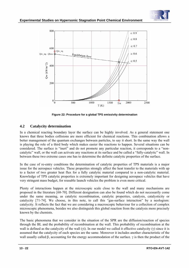
4.1 Emissivity determination If one considers TPS testing with an “equilibrium” probe type, it allows to impose high heat-flux comparable to the one of a planetary re-entry without any chemistry involve. In these conditions the outer edge enthalpy could be determined by heat-flux measurement and the rebuilding procedure, as presented above, with the rest of the parameters for the SPR. In that case the heat-flux reaching the wall could be computed depending on the surface temperature (Tw) by the BL code, it is also given by equation (5).
With a TPS sample mounted in an equilibrium-probe type and instrumented as it is shown in figure 9 the heat transfer at the surface can be expressed like :
Qweq(Tw) = σ.ε.(Tw)4 + Qcond (19)
Qweq is the heat-flux measured by the water-cooled calorimeter for the equilibrium-probe and Qcond is the conductive heat-flux passing through the insulating material at the back of the TPS sample and measured by a calorimeter (fig. 9). One can plot in the same graph (Qweq(Tw) - Qcond) and a family of curves fε(Tw)=σ.ε(Tw)4 for several ε values. They intercept for different Tw (fig. 22). The global emissivity coefficient could be determined by measuring the surface temperature of the sample (Tw) in the testing condition. A precise experimental set-up with several pyrometers, properly calibrated, is required to achieve accurate surface measurements in this situation. At VKI it is proposed to proceed at a first estimation with a 2-colors pyrometer, calibrated in its experimental environment.
Experimental Studies on Hypersonic Stagnation Point Chemical Environment
13 - 22 RTO-EN-AVT-142
Figure 22: Procedure for a global TPS emissivity determination
4.2 Catalycity determination In a chemical reacting boundary layer the surface can be highly involved. As a general statement one knows that three bodies collisions are more efficient for chemical reactions. This combination allows a better management of the quantum exchanges between particles, to say it short. In the same way the wall is playing the role of a third body which makes easier the reactions to happen. Several situations can be considered. The surface is “inert” and do not promote any particular reaction, it corresponds to a “non-catalytic” wall, or the wall can activate any reactions at its surface and be called a “fully-catalytic” wall. In between these two extreme cases one has to determine the definite catalytic properties of the surface.
In the case of re-entry conditions the determination of catalytic properties of TPS materials is a major issue for the aerospace vehicles. These properties strongly affect the heat transfer to the materials with up to a factor of two greater heat flux for a fully catalytic material compared to a non-catalytic material. Knowledge of TPS catalytic properties is extremely important for designing aerospace vehicles that have very stringent mass budget, for reusable launch vehicles the problem is even more critical.
Plenty of interactions happen at the microscopic scale close to the wall and many mechanisms are proposed in the literature [68-70]. Different designation can also be found which do not necessarily come under the same meaning, as catalytic recombination, catalytic properties, catalysis, catalysticity or catalycity [71-74]. We choose, in this note, to call this “gas-surface interaction” by a neologism: catalycity. It reflects the fact that we are considering a macroscopic behaviour for a collection of complex microscopic phenomena, besides we also distinguish this global reaction from the catalysis more precisely known by the chemists.
The basic phenomena that we consider in the situation of the SPR are the diffusion/reaction of species through the BL and the probability of recombination at the wall. This probability of recombination at the wall is defined as the catalycity of the wall (γi). In our model we called it effective catalycity (γ) since it is assumed that the catalycity of each species are the same. Moreover it includes another characteristic of the wall usually called β, accounting for the energy accommodation of the surface. γ is then the product of the

Experimental Studies on Hypersonic Stagnation Point Chemical Environment
RTO-EN-AVT-142 13 - 23
recombination probability γi, assumed equal for all species, with β. It appears as a production term for the boundary condition in the BL problem to compute. This term is built with the impinging mass flux (mi.Mi↓) multiply by the probability coefficient γ:
ωicat = γ.mi.Mi↓ (20)
For a fully catalytic wall γ equal 1 and for a non-catalytic wall γ equal 0. For a finite catalycity γ takes a value between 0 and 1 which represents the ability of the surface to enhance recombination. This boundary condition is implemented in the BL code to compute the heat-transfer at the wall depending on γ.
The determination of the catalycity by a plasmatron testing in stagnation point configuration results in an identification process. Heat-flux combined with pressure measurements with the standard probe are primarily achieved on a reference copper water-cooled calorimeter for which γ is assumed to be 1. This hypothesis is often done for convenience and its validity will be discussed in the following section. It allows to consider that the measurement corresponds fairly to the equilibrium heat-flux. Nevertheless one can point out that the equivalence between the equilibrium heat-flux and the heat-flux on a fully-catalytic surface is strictly valid only if Le =1.
In any case starting with a heat-flux and a pressure measurement the rebuilding procedure allows to determine the enthalpy, and the other parameters of the SPR, as soon as the corresponding NDP are given with a known catalycity. Thus the enthalpy is obtained for the experimental conditions.
With this value and the parameters of the SPR the heat-transfer (Qw) can be computed varying the surface temperature with γ as parameter. A series of curves are obtained which form a heat-flux abacus, in a Qw-Tw plot, from the fully catalytic condition to non-catalytic one (fig. 23). The TPS sample to be tested is placed in the same stagnation point condition (same plasma jet with same probe geometry) and the surface temperature (Ts) with the total heat-flux at the surface (Qtot) are measured by a 2-colors pyrometer for the radiative part and a water-cooled calorimeter for the conductive one (fig. 9). By plotting the experimental results (Qtot, Ts) on the heat-flux abacus the effective catalycity can be identified by interpolation (fig. 23).
Figure 23: Example of heat-flux abacus for γ identification

Experimental Studies on Hypersonic Stagnation Point Chemical Environment
13 - 24 RTO-EN-AVT-142
This γ determination method is based on several hypotheses and models that have to be furthered checked, but it already allows to characterize a surface material for TPS design. It is a quite long procedure (fig. 24) and one has to assess the accuracy and the validity of the hypotheses at each step. Such checking has been initiated at VKI carrying out a critical approach on the numerical side [60] and a careful calibration on the experimental side [36]. It has been found that the uncertainty on the catalycity determination is mainly due to the heat-flux measurement in relation to the enthalpy rebuilding. A precise set-up operating with successive probe injection for the testing is highly recommended to get rid of the repeatability issue of the plasma testing.
Figure 24: Procedure for effective catalycity determination
4.3 Reference catalycity determination By looking closer, the previous method for catalycity determination provides only a relative value for the effective catalycity compared to the cold copper surface which is taken as reference. The determination procedure in itself does not present major limitation except the fact that the reference catalycity is not known and is assumed to be 1 a priori. This assumption is somehow not realistic and present some physical inconsistency as it is often pointed out [19]. It is usually said that it can be viewed as an ideal situation and because of the typical S-curve of Qw vs. γ and the uncertainty on calorimeter measurements only the “highly catalytic” hypothesis for the copper surface is of importance. Taking γ=1 will not change drastically the results and is in some way a conservative approach for TPS design. Nevertheless the situation can be sometime more critical and a better accuracy on the value of γ is required. In this case one should work with a known value of γ as reference or determine the reference catalycity. It could be thought to carry out these measurements in another facility as a chemical reactor which allows an absolute determination. But such experiments are not easy to realise due to the oxidation of the surface cause by the low operating pressure of those devices. Moreover, as for the heat-flux calibration, the measurement should be done in the proper experimental condition to do it at best.
In this path, a new determination process has been set-up at VKI. At first one can remark that the rebuilding procedure, presented above (section 4.2), could function starting with any γ value, as well as the heat-flux abacus computed by the BL code for the γ-determination. These two processing programmes need only a reference catalycity. The first one rebuild an enthalpy (He) at the outer edge of the BL from the reference measurement when the second one determines a catalycity from the test measurements. The
Experimental Studies on Hypersonic Stagnation Point Chemical Environment
RTO-EN-AVT-142 13 - 25
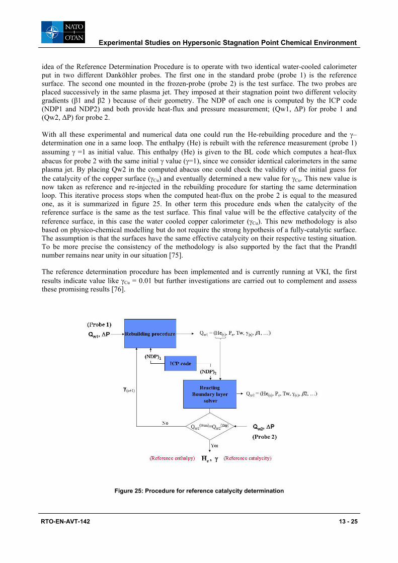
idea of the Reference Determination Procedure is to operate with two identical water-cooled calorimeter put in two different Danköhler probes. The first one in the standard probe (probe 1) is the reference surface. The second one mounted in the frozen-probe (probe 2) is the test surface. The two probes are placed successively in the same plasma jet. They imposed at their stagnation point two different velocity gradients (β1 and β2 ) because of their geometry. The NDP of each one is computed by the ICP code (NDP1 and NDP2) and both provide heat-flux and pressure measurement; (Qw1, ∆P) for probe 1 and (Qw2, ∆P) for probe 2.
With all these experimental and numerical data one could run the He-rebuilding procedure and the γ–determination one in a same loop. The enthalpy (He) is rebuilt with the reference measurement (probe 1) assuming γ =1 as initial value. This enthalpy (He) is given to the BL code which computes a heat-flux abacus for probe 2 with the same initial γ value (γ=1), since we consider identical calorimeters in the same plasma jet. By placing Qw2 in the computed abacus one could check the validity of the initial guess for the catalycity of the copper surface (γCu) and eventually determined a new value for γCu. This new value is now taken as reference and re-injected in the rebuilding procedure for starting the same determination loop. This iterative process stops when the computed heat-flux on the probe 2 is equal to the measured one, as it is summarized in figure 25. In other term this procedure ends when the catalycity of the reference surface is the same as the test surface. This final value will be the effective catalycity of the reference surface, in this case the water cooled copper calorimeter (γCu). This new methodology is also based on physico-chemical modelling but do not require the strong hypothesis of a fully-catalytic surface. The assumption is that the surfaces have the same effective catalycity on their respective testing situation. To be more precise the consistency of the methodology is also supported by the fact that the Prandtl number remains near unity in our situation [75].
The reference determination procedure has been implemented and is currently running at VKI, the first results indicate value like γCu = 0.01 but further investigations are carried out to complement and assess these promising results [76].
Figure 25: Procedure for reference catalycity determination

Experimental Studies on Hypersonic Stagnation Point Chemical Environment
13 - 26 RTO-EN-AVT-142
4.4 The 0-model It has already been mentioned that innumerable microscopic phenomena are happening at the surface in a reacting boundary layer. The effective catalycity (γ) that is defined in a previous section is only a global coefficient that helps to characterize catalytic properties in the purpose of TPS design. The catalycity property of a surface is implemented as a production term for the boundary condition of the BL problem to solve. The formulation of this term comes under a proper modelling which is used for the data processing of the experimental results. This reflects the fact that the methodology presented is a determination of catalycity and not a direct measurement of it. The point here is not to list or discuss the large number of models which can be found in the literature but rather to propose a simple view. As experimentalist in the perspective of surface properties characterization for TPS design it is always an interest to adopt a global approach for catalycity. Nevertheless the model used should be simple enough without being simplistic. Considering one of the simplest models in use a first approach can be find, in the early work of Goulard, where the gas-surface interaction is treated as an additional first order reaction [71]:
ωi = ki.ρi.Ci (21)
A second approach currently used is the one presented in this lecture which defines a recombination probability (γ) for the flux impinging on the wall, given by (20).
Each of this approach is appealing by its simplicity but none of these formulation gives a wall chemical composition that tends correctly to the local equilibrium composition for a fully catalytic wall as it has often been remarked [19]. Some new formulations help to remove their inconsistencies as it is proposed by Sarma [77] for the first approach and Rini for the second one [78]. But in one hand the first order reaction imposed at the wall appears not really justified for high temperature surfaces and in the other hand imposing γ = 1 is strictly speaking no physical since it should remain an asymptotic value.
If one wants to treat catalysis at the wall with a global approach, it can be simply consider that the reactions are accelerated at the wall. Instead of looking at “gas-surface reactions” one could focus on “gas reactions at the surface”. In this view, no specific model is needed for the reaction at the wall but the set of equations for gas chemistry is conserved and their reaction rate are multiplied by a “booster-coefficient” for the condition at the wall, to indicate that the reactions could happen faster at this location:
kfS = kf*10w kbS = kb*10w w : [0, ∞[ (22)
kfS, kbS are the forward and backward reaction rate for the gas chemistry at the surface and the catalytic property of the surface is defined by:
w = 0 for non-catalytic surface. w = ∞ for a fully catalytic surface.
We propose to call this simple model the “0-model” since no specific model are implemented for the wall which is simply considered as a location where gas chemistry could happen faster. This approach has several advantages:
The physical nature of the catalysis is preserved, the wall has a role of a catalyst which is not involved in the reaction but helps them to happen. The wall chemical composition is no more a problem since the final chemical state is ruled by the gas chemistry which is automatically coherent with the wall condition. Finally the catalycity which is still defined as a probability of recombination is now an outcome of the BL solution. The catalycity (γi) can be processed for each specie with the diffusion fluxes computed by the BL solver. The same expression as before can be rearranged to give:

Experimental Studies on Hypersonic Stagnation Point Chemical Environment
RTO-EN-AVT-142 13 - 27
ii
i
mMJi
⋅=
↓
γ (23)
γ = 1 remains an asymptotic situation and for w = 0 there is no catalycity and the wall behave chemically as part of the gas at its surface temperature. The 0-model presents many benefits to deal with a simple and coherent model. It is currently implemented on VKI code to test its efficiency for ground testing situation. Further fine consideration can be made for its improvement but it is believed to be a efficient tool to deal with the characterization of the TPS catalytic properties.
5 CONCLUSIONS Experimental hypersonic stagnation point studies are at the confluence of many aspects of aerothermochemistry. At this point the reproduction of the real flight conditions in a high enthalpy wind tunnel requires a specific methodology, adapted to the ground testing facility. For a plasmatron facility the LHTS methodology has been proved to be accurate and efficient. Nevertheless a great care has t be taken to set-up the plasma facility and design the experiment environment because many disturbances can occur to perturb the ideal stagnation point configuration. To ensure accurate flight duplication as well as to support material testing that aim to determine fine properties of the TPS the quality of the measurements is of first importance. To that purpose careful probe design together with extensive calibration campaign must be carried out.
In these investigations experiments and computations are intimately linked on two levels. Firstly through a rebuilding procedure which leads to the characterization of the flow parameters of the stagnation point, and secondly because the measurements are interpreted with physico-chemical models implemented in a proper boundary layer solver.
With all these tools we were able to treat the stagnation point as a local chemical reactor in which a Damköhler number has been defined to scale the chemical environment produced in the ground testing facility. Measurement probes have been designed to expand the testing capabilities of the facility in a wide range of chemical non-equilibrium situation. Applications of these developments have been presented for emissivity and catalycity determination of TPS. An innovative method for the determination of the reference catalycity has been explained, it results in a definite improvement for the characterization of TPS catalytic properties.
A new model for the surface catalycity has been proposed to keep a simple approach avoiding major inconsistencies. It is called the “0-model”, since no specific models are considered for the wall, but involves only gas chemistry which can be accelerated at the wall by a booster-coefficient for the chemical rates.
Finally some questions should be raised. As a first one everybody could wonder which chemical model has to be used for the hypersonic stagnation location. This study cannot reply directly since it is based on existing models, at least a relative comparison could be done. But the experimental set-up in its stagnation point configuration with its careful characterization methodology is a useful basis for laser based diagnostics which could investigate such problems for these reacting flows.
More practically stagnation point as it is treated in these studies requires axisymetry and steadiness which are situations not likely to happen easily in nature. At this point very diligent efforts must be done on the experimental set-up to assess the testing conditions. Most of the attention should be focused on the ICP torch design which represents the most sensitive part of the plasma wind tunnel. Very instructive investigations are currently carried out at VKI on those problematic [32].

Experimental Studies on Hypersonic Stagnation Point Chemical Environment
13 - 28 RTO-EN-AVT-142
At the end a more fundamental interrogation concerns the nature of the dissociated flow generated in a ground testing facility. One could ask how the reacting flow present at the nose of an hypersonic vehicle could be compared to the one produced by an electrical discharge on a ground based facility. Certainly optical diagnostics should be involved for free stream characterization since LTE appears as a unique reference which is important to check in the facilities. But flight experiments are also essentials to consider since a lot still to be learnt concerning real hypersonic flights to address at best ground studies from numeric and experimental sides.
6 ACKNOWLEDGEMENTS
The author would like to thank Sophie Herpin and Hyun Woo Krassilchikoff, VKI students, Cem Asma, VKI research engineer and Pascal Collin, VKI Technician for their useful and efficient collaboration in the VKI Plasmatron experimental studies.
7 REFERENCES
[1] AGARD, Aerothermodynamics of Hypersonic Vehicles, AGARD R-761, 1988.
[2] Dorrance WH, Viscous Hypersonic Flow, MacGraw-Hill, New York, 1962.
[3] Anderson, J.D. Jr., Hypersonic and high temperature gas dynamics, MacGraw-Hill Book Compagny, New York, 1989.
[4] Fay, J.A., Riddell, F.R., Theory of stagnation point heat transfer in dissociated air, Journal of Aeronautical Sciences, Vol. 25, No. 2, February 1958, p. 73-85.
[5] Neumann R.D., Experimental Methods for Hypersonics: Capabilities and Limitations, 2nd Joint Europe-US Short Course on Hypersonic: GAMNI-SMAI and Uni. Of Texas at Austin, USAF Academy, Colorado springs, CO 80840, January 1989.
[6] Ferri, A., Hypersonic flight testing, International Science and Technology, April 1964, pp 64-76.
[7] Winovich, W., Carlson, W.C.A., The 60-MW Shuttle interaction heating facility, 25th Int. Instr. Symposium, Anaheim, May 1999.
[8] Caristia, S., De Fillipis, F., SCIROCCO Project a major plasma wind tunnel for the year 2000, proceeding of International Symposium on Atmospheric Re-entry Vehicles and Systems, Arcachon (F), 16-18 May 1999.
[9] Gordeev, A.N., Overview of characteristics and experiments in IPM plasmatrons, RTO-VKI Special course. Measurement Techniques for High Enthalpy and Plasma Flows, October 1999
[10] Bottin, B., Carbonaro, M., Decré, M., Mazauric, S., Novelli, A. Design of a new inductively-coupled plasma wind tunnel for reentry material testing at the von Kármán Institute, Wind tunnels and wind tunnel test techniques, Cambridge (UK), 1997.
[11] Vincenti W.G., and Kruger, C.H., Introduction to Physical Gas Dynamics, John Wiley & Sons, 1965.
[12] Park, C. Nonequilibrium Hypersonic Aerothermodynamics. John Wiley & Sons, 1990.

Experimental Studies on Hypersonic Stagnation Point Chemical Environment
RTO-EN-AVT-142 13 - 29
[13] Lees L., Laminar heat transfer over blunt-nosed bodies at hypersonic flight speed, Jet Propulsion, Vol. 26, April 1956, pp. 259-269.
[14] Cohen, K, Reshotko, E., Similar solutions for the compressible laminar boundary layer with heat transfer and pressure gradient, NACA TN 3325, 1955.
[15] Rose P.H., Stark W.I., Stagnation-point heat transfer measurements in dissociated air, J. Aeron. Sci., Vol. 25, No. 2, February 1958, pp. 86-97.
[16] Bleakney, W., Weimer, D.K., and Fletchner, C.H., The shock tube: A facility for investigations in fluid dynamics, Review of Scientific Instruments, Vol. 20, pp. 807-815, November, 1949.
[17] Warren W.R. & Diaconis N.S., Air arc simulation of hypersonic environments, ARS Int. Hyp. Conf. Cambridge, Massachusetts, Aug. 16-18, 1961.
[18] Kolesnikov, A. Extrapolation from high enthalpy tests to flight based on the concept of LHTS. Belgium. RTO-VKI Special course. Measurement Techniques for High Enthalpy and Plasma Flows, October 1999.
[19] Barbante, P.F. : Accurate and Efficient Modelling of High Temperature Nonequilibrium Air Flows. PhD thesis, Université Libre de Bruxelles, May 2001.
[20] Bottin, B., Chazot, O., Carbonaro, M., Vander Haegen, V., Paris, S. : The VKI Plasmatron Characteristics and Performances. Belgium. RTO-VKI Special Course. Measurement Techniques for High Enthalpy and Plasma Flows, October 1999.
[21] Barbante, P.F., Chazot, O., Flight extrapolation of plasma wind tunnel of stagnation region flowfield, J. Thermophys. Heat Transfer, (accepted for publication)
[22] Babat, G.I., Electrodeless discharges and some allied problems, J. Institution of Electrical Engineers, part III, 94 (27), January 1947, pp 27-37
[23] Boulos M. I., The inductively coupled R.F.plasma, Pure & Appl. Chem., vol. 57, 1985, pp 1321-1352
[24] Reed T. B., induction- coupled plasma torch, J. Appl. Phys., vol. 32, 1961, pp 821-824.
[25] Dunken H., Pforr G., Z. Chem., vol. 6, 1966
[26] Mermet J.M., Trassy C., A plasma torch configuration for inductively coupled plasma as a source in optical emission spectroscopy and atomic absorbtion spectroscopy, Appl. Spectrosc. vol. 31, 1977, pp 237-239
[27] Allemand C. D., Barnes R.M., A study of inductively coupled plasma torch configurations, Appl. Spectrosc. vol. 31, 1977, pp 434-443
[28] Rezaaiyaan R., Hieftje G.M., Anderson H., Kaiser H., Meddings B., Design and construction of low-flow, low-power torch for inductively coupled plasma spectrometry, Appl. Spectrosc. vol. 36, 1982, pp 627-631

Experimental Studies on Hypersonic Stagnation Point Chemical Environment
13 - 30 RTO-EN-AVT-142
[29] Chazot, O., Van Der Haegen,V., Carbonaro, M. Flow visualization with a cold model for ICP torch design, Progress in Plasma Processing of Materials 1999, begell house, ,inc., New York, Wallingford, u.k., pp 41-47.
[30] Chazot, O., Study of flow field topology in an ICP torch by surface pressure measurements and numerical calculations, Progress in Plasma Processing of Materials 2001, begell house,inc., New York, Wallingford, u.k., pp 241-248.
[31] Vanden Abeele D., and Degrez, G., Efficient computational model for inductive plasmas flows. AIAA Journal, 38 (2), 2000, pp 234-242.
[32] Playez, M., VKI private communication
[33] Bottin, B., Carbonaro, M., Van Der Haegen, V., Paris, S. Predicted and measured capability of the VKI 1.2 MW Plasmatron regarding re-entry simulation, 3rd European Symposium on Aerothermodynamics for Space Vehicles, ESA SP-426, 1999, p.553-560.
[34] Bottin, B. Aerothermodynamic model of an inductively-coupled plasma wind tunnel. PhD Thesis, Université de Liège, October 1999.
[35] Caimano D., Chazot O., Calibration of Heat Flux Measurement and Development of data Acquisition System for Inductively Coupled Plasma Wind Tunnel, FLUCOME’03, 7th Triennial International Symposium on Fluid Control, Measurement and Visualization, Sorrento, August 25-28, 2003.
[36] Caimano D., Chazot O, D.A.S and Heat Flux Measurements for Plasma Wind Tunnels, VKI Technical Note, TN 202, December 2003.
[37] Sahin, P. Simultaneous pressure and heat-flux measurement in high-enthalpy facilities for aerospace applications. 2002. VKI SR 2002-26.
[38] Bonnewijn, S. Combined measurements in Plasmatron facility for planetary entry simulation. VKI SR. June 2003.
[39] Vera, I., Assessment of pressure and enthalpy rebuilding for simulation of planetary re-entry conditions in a plasmatron facility, August 2004, VKI SR 2004-37.
[40] Vanden Abeele, D., An efficient computational model for inductively coupled air plasma flows under thermal and chemical non-equilibrium. PhD Thesis, KU Leuven, November 2000.
[41] Magin, T., A model for inductive plasma wind tunnels, PhD Thesis, Université Libre de Bruxelles, June 2004.
[42] Bottin, B., Vanden Abeele, D., Carbonaro, M., Degrez, G., and Sarma G.S.R., Thermodynamic and transport properties for inductive plasma modelling. J. Thermophys. Heat Transfer, 13(3), July-September 1999, pp 343-350.
[43] Zoby, E.V., Empirical stagnation-point heat-transfer relation in several gas mixtures at high enthalpy levels, Langley Research Center, NASA TN D-4799, 1968.
[44] Marvin J.G., Deiwert G.S, Convective heat transfer in planetary gases, NASA TR R-224, 1965.

Experimental Studies on Hypersonic Stagnation Point Chemical Environment
RTO-EN-AVT-142 13 - 31
[45] Sutton, K., Graves R. A., A general stagnation point convective-heating equation for arbitrary gas mixtures, Langley Research Center, NASA TR R-376, 1971.
[46] Boison J.C. & Curtiss H.A., An Experimental Investigation of Blunt Body Stagnation Point Velocity Gradient, ARS Journal, Vol. 29, Feb. 1959, pp 130-135.
[47] Chazot O., R. Régnier and A. Garcia Muñoz, Simulation Methodology in Plasmatron Facility and Hypersonic Wind Tunnels, 12th International Conference on Method of Aerophysical Research, Akademgorodok, Novosibirsk, Russia, June 28 – July 4, 2004.
[48] Pirard, B., Experimental simulation of planetary re-entry condition in the VKI Plasmatron, September 2001, VKI SR 2001-29
[49] Regnier R., Rebuilding of re-entry conditions by combined measurements in a Plasmatron Facility, VKI SR 16, 2003.
[50] Sagnier P., Vérant, J.-L., Flow characterization in the ONERA F4 high-enthalpy wind tunnel, AIAA J., Vol. 36, No. 4, April 1998, pp. 522-531.
[51] De Fillipis F, Serpico M., Air high enthalpy stagnation point heat flux calculation, CIRA TN 96-014, Jan. 1996.
[52] Horton T.E., Babineaux T.L., Influence of atmosphere composition on hypersonic stagnation-point convective heating, AIAA J., Vol. 5, No. 1, January 1967, pp. 36-43.
[53] Rose P.H., Stankevics J.O., Stagnation-point heat transfer measurements in partially ionized air, AIAA J., Vol. 1, No.12, December 1963, pp. 2752-2763.
[54] Yee L., Bailey H.E., Woodward H.T., Ballistic range measurements of stagnation-point hat transfer in air and in carbon dioxide at velocities up to 18,000 feet per second, NASA TN D-777, 1961.
[55] Sagnier, P., Masson, A., Mohamed, A.K., Verant, J.L., and Devezeaux, D., Synthesis of mstp calibration campaigns in onera F4 hot shot wind tunnel, ONERA TP, 86, 1995.
[56] Krassilchikoff, H, Weinquin, V., Etude des conditions de simulations de rentrees atmospherique pour souffleries a haute enthalpie, VKI SR- 2005.
[57] Barbante P.F., Reacting flows simulation with application to ground to flight extrapolation. RTO-VKI Special course. Experiments, modelling and simulation of gas-surface interactions for reactive flows in hypersonic flights. February 2006.
[58] Pope R.B., Measurements of Enthalpy in Low-Density Arc-heated Flows, AIAA J., Vol. 6, No. 1, Jan. 1968, pp 103-110.
[59] Fletcher, D.G., Nonintrusive diagnostic strategies for arcjet stream characterization, Belgium. RTO-VKI Special course. Measurement Techniques for High Enthalpy and Plasma Flows, October 1999.
[60] Thömel, J., Local heat transfer simulation of air and CO2, July 2005, VKI PR 2005-01.
[61] Wicke, E. Gerhard Damköhler – Founder of chemical reaction engineering, International chemical engineering, 25, n. 4, Oct. 1985, pp 770-773.

Experimental Studies on Hypersonic Stagnation Point Chemical Environment
13 - 32 RTO-EN-AVT-142
[62] Baumgart, J., Design of an enthalpy probe, VKI SR 2002-12.
[63] Gokcen, T., Effects of flowfield nonequilibrium on convective heat transfer to blunt body, J. Thermophys. Heat Transfer, vol. 10, n.2, April-June 1996, pp 234-241.
[64] Herpin, S., Chemical aspects of hypersonic stagnation point heat transfer, August 2005, VKI PR 2005-10.
[65] Sureda, M., del Campo, V., Determination of Damköhler number at stagnation point in experimental simulation of re-entry conditions, August 2005, VKI SR 2005-36
[66] Park, C., Review of chemical-kinetics problems of future NASA Missions, I Earth Entries. J. of Thermophysics and Heat Transfer 7, 3 (1993), pp 385-398.
[67] Gnoffo, P.A., Gupta, R.N., Shinn, J.L., Conservation equations and physical models for hypersonics air flows in thermal and chemical nonequilibrium. Technical 2867, NASA (Langley), Virginia, 1989.
[68] Rosner, D.E., Recent advances in convective heat transfer with dissociation and atom recombination, Jet Propulsion, July 1958, pp 445- 451.
[69] Deutschmann, O., Riedel, U., and Warnatz, J., Modeling of Nitrogen and Oxygen Recombination on Partial Catalytic Surfaces, Journal of Heat Transfer, Vol. 117, 1995, pp. 495-501.
[70] Natsui, F., Barbato, M., and Bruno, C., Material-Dependent Catalytic Recombination Modeling for Hypersonic Flows, Journal of Thermophysics and Heat Transfer, Vol. 10, 1996, pp. 131-136.
[71] Goulard, R., On catalytic recombination rates in hypersonic stagnation heat transfer. Jet Propulsion 28, November 1958, pp 737-745.
[72] Stewart, D.A., “Surface Catalysis and Characterization of Proposed Candidate TPS for Access-to-Space Vehicles,” NASA TM-112206, July 1997.
[73] Neuman, R. D., Flight experiments for hypersonic vehicle development, RTO-AVT-VKI lectures series 2006.
[74] Chazot O., S. Paris, P. Collin, M. Bickel, T. Ullman, TPS Testing and Catalycity Determination in the VKI Plasmatron Facility, Atmospheric Reentry Vehicles and Systems Symposium, arcachon, France, March 2003.
[75] Bottin, B., Pegase 4.4 Tables of thermodynamic and transport properties for air and argon plasmas, December 1997, VKI IN 109.
[76] Krassilchikoff, H., VKI private communication.
[77] Sarma, G.S.R., Physico-Chemical Modelling in Hypersonic Flow simulation, Progress in Aerospace Sciences, 36, 3-4 (2000), pp 281-349.
[78] Rini, P., Garcia, A, Magin, T., Degrez, G., Numerical simulation of nonequilibrium stagnation line CO2 Flows with catalyzed surface reactions. J. of Thermophysics and Heat transfer vol. 18, n. 4, October-december 2004, pp 511-518.