experimental study in the effect of welding parameters on · pdf filethe important parameters...
TRANSCRIPT

International Journal of Advance Research In Science And Engineering http://www.ijarse.com
IJARSE, Vol. No.4, Special Issue (01), April 2015 ISSN-2319-8354(E)
503 | P a g e
EFFECT OF PROCESS PARAMETERS ON FRICTION
STIR WELDED AA 6061 ALUMINUM ALLOY BUTT
JOINTS.
P.Srinivasulu1, Dr.G. Krishnamohan Rao
2, M.SatyanarayaGuptha
3
1Assoc.Prof. of Mechanical Engineering, Vaagdevi College of Engineering, Warangal, TS, (India)
2Professor, Department of Mechanical Engineering, JNTUH-Hyderabad, TS (India)
3Professor of Mechanical Engineering, MLRIT, Hyderabad, TS, (India)
ABSTRACT
Friction stir welding is a solid state welding process for joining metallic alloys has emerged as an alternative
technology used for high strength alloys that are difficult to join with conventional techniques. The applications
of FSW Process are found in several industries such as aerospace, automotive and marine industries for joining
Aluminum, magnesium and copper alloys. The FSW Process parameters such as rotational speed, welding
speed, tool pin profile, tilt angle, plunge speed, axial force play vital role in the analysis of weld quality
deciding joint strength. AA6061 aluminum alloy (A1mg-si) has widely used in fabrication of light weight
structures. An attempt has been made to investigate the effect of different welding parameters on the weld
quality of AA6061 aluminum alloy. Cylindrical pin profile is used for tool pin profile in this research. The
quality of the weld is well and no defect is found using this tool. Consequently, the obtained results explained
the variation of stress as a function of strain and the effect of different welding parameters on yield strength,
ultimate tensile strength & elongation.
Keywords: Friction Stir Welding, AA6061 Aluminum Alloy, Tool Rotational Speed, Welding
Speed, Mechanical Properties.
I. INTRODUCTION
Friction stir welding (FSW) is a solid state joining Process developed and patented by the welding institute
(TWI), UK in 1991[1]. FSW is a continuous, hot shear, auto genius Process involving a Non-consumable
rotating tool of the harder material then the base Material. FSW has emerged as welding Technique used in high
strength alloys (2xxx, 6xxx, 7xxx and 8xxx series) for Aerospace, automotive and marine applications [2] that
were difficult to join with conventional Techniques. Defect free welds with good mechanical Prosperities have
been made with FSW in a variety of aluminum alloys. This solid state process leads to minimal micro
structural changes and better mechanical prosperities then conventional welding. In this investigation, an
attempt has been made to understand the effect of parameters on the weld quality of AA6061 alloys using FSW
process. Cylindrical pin is used as tool pin profile in this research. The pin traveled longitudinally at different
welding speeds (mm/min) and the tool rotation speed was held between 800Rpm to 1500Rpm in all of the
experiments. Consequently the appearance of the weld for different welding parameters has been examined by

International Journal of Advance Research In Science And Engineering http://www.ijarse.com
IJARSE, Vol. No.4, Special Issue (01), April 2015 ISSN-2319-8354(E)
504 | P a g e
using x-ray Radiography technique and the Impact of the stress as a function of strain and the effect of different
welding parameters on ultimate tensile strength yield strength and elongation are analyzed.
II. FRICTION STIR WELDING PROCESS
FSW is produced by rotating and plunging a specially designed cylindrical, shouldered tool with a small
diameter pin into the joint line between two butted plates [3]. Frictional heat causes the metal to soften and
allows the tool to traverse along the joint line. In this process, the two plates are clamped on a rigid back plate.
The fixturing prevents the plates from spreading apart or lifting during welding. The welding tool, consists of a
shank, Shoulder and pin, is then rotated to a prescribed speed. The tool is slowly plunged in to the work piece
material at the butt line, until the shoulder of the tool forcibly contacts the upper surface of material and pin is a
short distance from the back plate. A downward force is applied to maintain the contact and a short dwell time
(10sec) is observed to allow for the development of the thermal fields for preheating and softening the material
along the joint. Upon reaching end of the weld, the tool is withdrawn while it is still being rotated. As the pin is
withdrawn, it leaves a keyhole at the end of the weld. The FSW process of butt joint is as shown in fig 1, the key
hole at the end of the weld as shown in fig 2.
Fig 1. Principle of the FSW process for butt joints. Fig2.Key holes at the end of the welds.
III. SELECTION OF MATERIAL
Aluminum Alloy AA 6061:- Aluminum alloy AA 6061 is a high strength alloy with excellent corrosion
Resistance. This alloy is known as structural alloys. In plate form, AA 6061 is the alloy most commonly used
for machining. The addition of large amount of manganese controls the grain structure which in turn results in a
stronger alloy.
Table1:- Chemical Composition of Aluminum alloy AA 6061 (wt%)
Si Fe Cu Mn Mg Ti Cr Others Aluminum
0.598 0.343 0.265 0.07 1.095 0.016 0.204 0.048 Balance
Table2:- Mechanical Properties of Aluminum alloy AA 6061.
Base material AA 6061
Density (X 1000 kg/m3 ) 2.7
Elastic Modulus (Gpa) 70

International Journal of Advance Research In Science And Engineering http://www.ijarse.com
IJARSE, Vol. No.4, Special Issue (01), April 2015 ISSN-2319-8354(E)
505 | P a g e
Ultimate Tensile Strength (Mpa) 240.921
Yield Strength (MPa) 176.247
Hardness (VHN)5kg 105
Percentage Elongation 16.78
IV. TOOL DESIGN
Tool design influences heat generation, plastic flow, the power required and the uniformity of the Welded Joint
[4]. The shoulder generates most of the heat and prevents the plasticized material from escaping from the work
piece while, both the shoulder and the tool pin affect the material flow. Friction Stir Welded Tool in this study
as shown in fig3.
Fig 3: Schematic Diagram of Tool pin Profile.
V. SELECTION OF PROCESS PARAMETERS
The important parameters affecting tensile strength are tool rotational speed, welding speed, plunge speed, tool
tilt angle, axial load, tool penetration depth. Out of these parameters such as tool tilt angle and axial load can be
varied only on machines dedicated to FSW. The other factors which primarily affect the strength of the joint yet
can be varied easily on any vertical machine centre are tool rotation speed (N), tool traverse speed (V) and tool
plunge speed (P). Therefore these three parameters are chosen in the present study.
VI. TOOL MANUFACTURING
The FSW Tool is designed for this Research is tool pin profile of cylinder of D/d ratio 3. Out of various Tool
materials like tool steel, High speed steel (HSS), high carbon chromium steel, carbon and carbon boron nitride,
among which HSS steel is chosen as Tool material because of it’s high strength, high hot hardness, easy to
process, easily available and low cost. The FSW tool is manufactured using CNC Turning centre and wire cut
EDM (WEDM) machine. The tools are oil hardened to obtain a hardness of 60-62 HRC.
The tool material properties as given in table (3). The hardening temperature of HSS-M2 is 1240-12900C, the
quenching medium is oil/air, the tempering temperature is 550-5800C and Brinel Rockwell hardness is 64-66.
International Journal of Advance Research In Science And Engineering http://www.ijarse.com
IJARSE, Vol. No.4, Special Issue (01), April 2015 ISSN-2319-8354(E)
506 | P a g e
Table3: Chemical Composition of Tool Material
C Si MN Cr Ni W Co V Mo
0.75-0.9 0.10-
0.35
0.20-
0.40
3.57-
4.50
- 5.50-
6.50
- 1.75-
2.00
5.50-
6.50
VII. WELDING PARAMETERS
The initial Joint Configuration was obtained by securing the plates in position using mechanical clamps. The
direction of welding as normal to the rolling direction. Single pass welding procedure was used to fabricate the
joint. The welding parameters used to fabricate the joints are presented in Table (4). Welding parameters
influence the friction stir welded joints. If the tool rotational speed increases, it shows that there is a increase in
elongation [5].
Table 4:- Welding Parameters
Welding Parameters/Range Minimum(-) Maximum(+)
Tool Rotational Speed (Rpm) 800 1500
Welding Speed (mm/min) 30 80
Plunge Speed (mm/min) 10
20
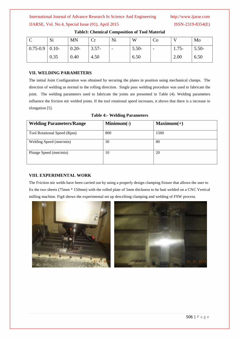
VIII. EXPERIMENTAL WORK
The Friction stir welds have been carried out by using a properly design clamping fixture that allows the user to
fix the two sheets (75mm * 150mm) with the rolled plate of 5mm thickness to be butt welded on a CNC Vertical
milling machine. Fig4 shows the experimental set up describing clamping and welding of FSW process.

International Journal of Advance Research In Science And Engineering http://www.ijarse.com
IJARSE, Vol. No.4, Special Issue (01), April 2015 ISSN-2319-8354(E)
507 | P a g e
Fig4. Experimental Set up Describing Clamping and Welding of FSW Process
In this investigation the base material AA 6061 which is widely used in aircraft and auto motive applications
due to its high strength. FSW plates were examined using X- ray Radiography. There were no apparent defects
in welded plates.
IX. DESIGN OF EXPERIMENTS
Table 5: Design of Experiments (DOE)
EXP No Speed
(N)Rpm
Welding
speed(f)
(mm/min)
Plunge
Speed
(mm/min)
Fu
(N/mm2)
Fy
N/mm2
%
elongation
1 1500 80 20 115.749 114.597 2.48
2 1500 80 10 118.07 114.578 3.76
3 1500 30 20 114.56 113.38 3.3
4 1500 30 10 96.653 96.653 4.7
5 800 80 20 117.025 117.025 2.6
6 800 80 10 117.025 117.025 2.66
7 800 30 20 134.6 134.6 2.1
8 800 30 10 119.89 109.9 3.7
X. MECHANICAL TESTS
Friction stir welded samples were tested for tensile, impact, microstructure and micro hardness properties. The
testing procedures, geometry of the samples including dimensions as per ASTM standards.
10.1 Tensile Test Plain tensile strength and notch tensile strength are carried on UTM (10,000Kgf). The ASTM standard test
samples are shown in fig 5 & fig6.

International Journal of Advance Research In Science And Engineering http://www.ijarse.com
IJARSE, Vol. No.4, Special Issue (01), April 2015 ISSN-2319-8354(E)
508 | P a g e
Fig5: Tensile Test Sample
Fig6: Notch Tensile Sample
10.2 Impact Test Impact test samples are prepared from the welded joint. The charpy V- notch impact toughness test carried on
FIT-300(EN) machine. ASTM standard test sample as shown in fig (7).
Fig 7: Impact Toughness Test Sample

International Journal of Advance Research In Science And Engineering http://www.ijarse.com
IJARSE, Vol. No.4, Special Issue (01), April 2015 ISSN-2319-8354(E)
509 | P a g e
10.3 Hardness Test
The samples are cut from welded joints by wire cut EDM and polished and etched. Micro hardness tests were
conducted using digital micro hardness tester. A 100 gram load is applied for all the samples for a period of
15secs while measuring the hardness. The micro hardness was measured at equal intervals across weld ments.
10.4 Bend Test
Bend tests were carried out using UTM (10000 Kgf) tester. 90˚ bend tests were conducted. The ASTM standard
bend test specimen as shown in fig8.
Fig8: Bend Test Specimen
10.5 Metallography
A low magnification Metscope -1 make was employed for observing the beed shape. The friction stir welded
samples were sectioned by using wire cut EDM. Silver mirror image is obtained after following the standard
procedural steps of Metallography. Etching is done carefully using Keller’s regent (3ml Hcl, 5ml HNO3, 2ml HF
and 190ml distilled water). Micro scope was used for determination of microstructures at various locations.
XI. RESULTS & DISCUSSIONS
11.1 Visual Inspection
Visual inspection of the welds revealed that the welds are of high quality and defect free. However pin holes are
formed at being and termination of the tool along centre line of weld. Surface roughness and semi circular
striations are found in weld made at low welding speeds. Welds are smooth at high welding speed.
11.2 Tensile Strength Test
It is observed that the increase in rotational speed has resulted in increases of Tensile strength. The reason is
that higher the speed, the higher will be the deformation and heat generation in the weld. This will result in
finer grain structures, because of which tensile strength is increases. The result by tensile test which was
observed during the experiments were shown in Graphs 1 to 8. The fractured specimens as shown in fig (9).

International Journal of Advance Research In Science And Engineering http://www.ijarse.com
IJARSE, Vol. No.4, Special Issue (01), April 2015 ISSN-2319-8354(E)
510 | P a g e
Fig 9. Fractured Specimens after Tensile Test
Graph 1.Stress-Strain Diagram for Specimen 1 Graph2.Stress-Strain Diagram for Specimen 2
Graph 3.Stress-Strain Diagram for Specimen 3 Graph4.Stress-Strain Diagram for Specimen 4

International Journal of Advance Research In Science And Engineering http://www.ijarse.com
IJARSE, Vol. No.4, Special Issue (01), April 2015 ISSN-2319-8354(E)
511 | P a g e
Graph 5.Stress-Strain Diagram for Specimen 5 Graph6.Stress-Strain Diagram for Specimen 6
Graph 7.Stress-Strain Diagram for Specimen 7 Graph8.Stress-Strain Diagram for Specimen 8
11.3 Notch Tensile Test
The specimens prepared for notch tensile test as shown in fig 10(a).The Failure of the specimens during notch
tensile test as shown in fig 10(b). The yield strength, ultimate tensile strength & %elongation during notch
tensile test for all the specimens are tabulated in table (6). The stress-strain Graphs during notch tensile test as
shown below. Notch Tensile test is carried on TUE-600(C).The ASTM test samples are prepared. The tensile
strength is decreasing when weld speed decrease. Stress Strain diagrams for specimens as shown in graphs 9-12.
Comparison of notch ultimate tensile stress, notch yield stress and % elongation with parent metal as shown in
figures 11(a), 11(b) and 11(c).
Fig (10) a) Notch tensile test specimens b) Notch tensile test specimens after failure
International Journal of Advance Research In Science And Engineering http://www.ijarse.com
IJARSE, Vol. No.4, Special Issue (01), April 2015 ISSN-2319-8354(E)
512 | P a g e
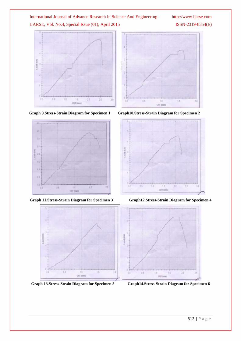
Graph 9.Stress-Strain Diagram for Specimen 1 Graph10.Stress-Strain Diagram for Specimen 2
Graph 11.Stress-Strain Diagram for Specimen 3 Graph12.Stress-Strain Diagram for Specimen 4
Graph 13.Stress-Strain Diagram for Specimen 5 Graph14.Stress-Strain Diagram for Specimen 6
International Journal of Advance Research In Science And Engineering http://www.ijarse.com
IJARSE, Vol. No.4, Special Issue (01), April 2015 ISSN-2319-8354(E)
513 | P a g e
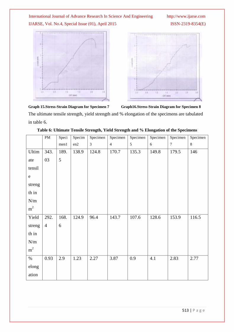
Graph 15.Stress-Strain Diagram for Specimen 7 Graph16.Stress-Strain Diagram for Specimen 8
The ultimate tensile strength, yield strength and % elongation of the specimens are tabulated
in table 6.
Table 6: Ultimate Tensile Strength, Yield Strength and % Elongation of the Specimens
PM Speci
men1
Specim
en2
Specimen
3
Specimen
4
Specimen
5
Specimen
6
Specimen
7
Specimen
8
Ultim
ate
tensil
e
streng
th in
N/m
m2
343.
03
189.
5
138.9 124.8 170.7 135.3 149.8 179.5 146
Yield
streng
th in
N/m
m2
292.
4
168.
6
124.9 96.4 143.7 107.6 128.6 153.9 116.5
%
elong
ation
0.93 2.9 1.23 2.27 3.87 0.9 4.1 2.83 2.77

International Journal of Advance Research In Science And Engineering http://www.ijarse.com
IJARSE, Vol. No.4, Special Issue (01), April 2015 ISSN-2319-8354(E)
514 | P a g e
Fig11 (a). Comparison of Notch Ultimate Tensile Stress
Fig11 (b). Comparison of Notch yield stress
Fig11(c). Comparison of % Elongation
11.4 Bend Test
Root and face bend tests were used as an important tool to understand about the ductility and toughness of
Friction Stir Welds.

International Journal of Advance Research In Science And Engineering http://www.ijarse.com
IJARSE, Vol. No.4, Special Issue (01), April 2015 ISSN-2319-8354(E)
515 | P a g e
As friction stir weld samples passes 900
bend as shown in fig 12(a). The root bend and face bend as shown in
fig12 (b), 12(c). The results reveal that at low welding speeds the specimens withstands maximum bending load.
The comparison of bending load on the root side and face side with parent metal as show in fig13 (a) and 13(b).
Fig 12 (a) Bend test set up (b) Root bend (C) Face bend
Table 7: Details of Bend Test for Root & Face bends comparing with parent metal
PM Speci
men1
Specimen
2
Specimen
3
Specimen
4
Specimen
5
Specimen
6
Specimen
7
Specimen
8
Root
Bend
8KN 7.85K
N
7.8 KN 7.9 KN 7.95 KN 7.9 KN 7.7 KN 7.9 KN 7.8 KN
Face
Bend
8KN 7.8
KN
7.8 KN 8 KN 7.9 KN 8.5 KN 7.9 KN 8 KN 8 KN
Fig 13(a) Comparison of Bending Load on Root Side
Fig.13 (b) Comparison of Bend Load for Face Side
International Journal of Advance Research In Science And Engineering http://www.ijarse.com
IJARSE, Vol. No.4, Special Issue (01), April 2015 ISSN-2319-8354(E)
516 | P a g e
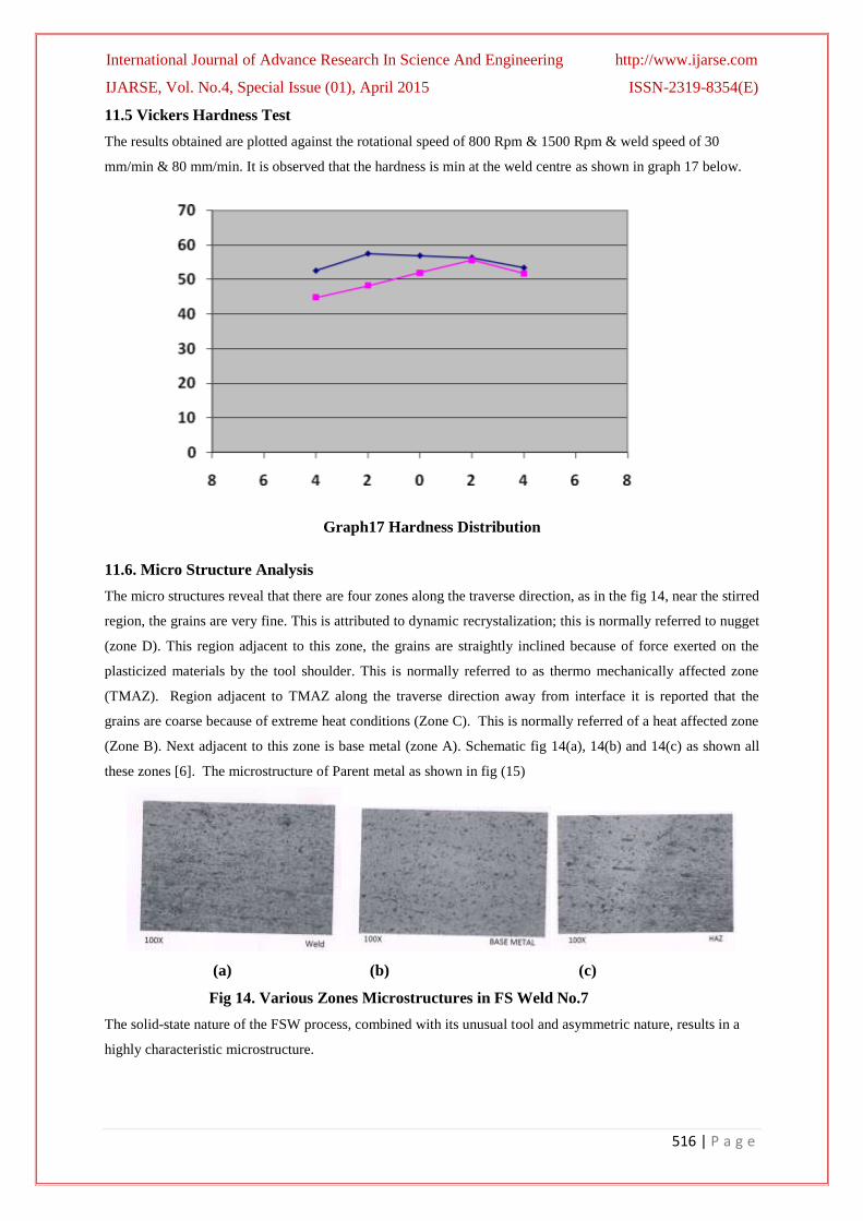
11.5 Vickers Hardness Test
The results obtained are plotted against the rotational speed of 800 Rpm & 1500 Rpm & weld speed of 30
mm/min & 80 mm/min. It is observed that the hardness is min at the weld centre as shown in graph 17 below.
Graph17 Hardness Distribution
11.6. Micro Structure Analysis
The micro structures reveal that there are four zones along the traverse direction, as in the fig 14, near the stirred
region, the grains are very fine. This is attributed to dynamic recrystalization; this is normally referred to nugget
(zone D). This region adjacent to this zone, the grains are straightly inclined because of force exerted on the
plasticized materials by the tool shoulder. This is normally referred to as thermo mechanically affected zone
(TMAZ). Region adjacent to TMAZ along the traverse direction away from interface it is reported that the
grains are coarse because of extreme heat conditions (Zone C). This is normally referred of a heat affected zone
(Zone B). Next adjacent to this zone is base metal (zone A). Schematic fig 14(a), 14(b) and 14(c) as shown all
these zones [6]. The microstructure of Parent metal as shown in fig (15)
(a) (b) (c)
Fig 14. Various Zones Microstructures in FS Weld No.7
The solid-state nature of the FSW process, combined with its unusual tool and asymmetric nature, results in a
highly characteristic microstructure.

International Journal of Advance Research In Science And Engineering http://www.ijarse.com
IJARSE, Vol. No.4, Special Issue (01), April 2015 ISSN-2319-8354(E)
517 | P a g e
Fig 15. Micro structure of Parent Metal AA 6061
By comparing all microstructures, with parent metal, the formation of very fine grain microstructure, uniformly
distributed fine precipitates and higher stir zone hardness are obtained in joint 7 at 800 RPM, 30mm/min feed at
20 mm/min.
11.7 IMPACT TOUGHNESS
Table 8, Gives the results of Charpy V-Notch impact toughness of the Friction Stir Welded Aluminum alloy
using cylindrical pin profile including that of the parent material. The comparison of the impact specimens and
specimen’s after failure as shown in fig 16(a) & 16(b). Impact toughness values for specimens including parent
metals as shown in table 8. The comparison of impact toughness of the welds with parent metals as shown in fig
17.
Fig 16 a) impact test specimens b) impact test specimens after failure
Table 8: Impact Toughness of Friction Stir Welding
Metal PM Specim
en1
Specim
en2
Specime
n3
Specime
n4
Specime
n5
Specime
n6
Specime
n7
Specime
n8
Impact
toughness
in Joules
42
36
35
30
38
30
48
48
38

International Journal of Advance Research In Science And Engineering http://www.ijarse.com
IJARSE, Vol. No.4, Special Issue (01), April 2015 ISSN-2319-8354(E)
518 | P a g e
Fig 17: Comparison of Impact Toughness of the Welds
Maximum toughness is reported in weld specimens 6 & 7 were the spindle speed is 800 Rpm; it is about 114%
as comparing with parent metal.
XI. CONCLUSION
1) FSW was successfully carried out on a CNC milling machine and the quality of the welded joints was found
to be satisfactory.
2) Friction stir welding of AA6061 alloy resulted in a dynamically recrystalized zone, TMAZ and HAZ. A
Softened region has clearly occurred in the friction stir welded joints of AA6061 alloy.
3) Mechanical properties of FS welded aluminum alloy AA6061 are influenced by process parameters.
4) Tensile strength of the FS welded joints is directly proportional to the travel speed, spindle speed and
plunge speed.
5) The tensile strength, yield strength, percentage elongation, Hardness, notch tensile properties of the welded
joints are lower than that of the parent metal.
6) The impact toughness of some of the specimens6 & 7 is more than that of the parent metal about 114%.
7) Bending load for face bend of specimen 4 is about 99.375% of parent metal. Where as bending load for root
bend of specimen 5 is about 106% of parent metal.
8) Hardness drop was observed in the weld region. This softening was mostly evident in the HAZ on the
advancing side of the welds. This zone corresponds to the failure location in tensile tests.
9) Maximum tensile strength is 134.6 N/mm2
in Joint No.7 with a spindle speed of 800 Rpm, travel speed
30mm/min & plunge speed is 20 mm/min.
10) Maximum yield strength is 134.6 N/mm2
in Joint No.7 with a spindle speed of 800 Rpm, travel
speed 30mm/min & plunge speed is 20mm/min.
11) Maximum % elongation is about 4.7% in joint 4 with a spindle speed 1500 Rpm ,travel speed is 30mm/min
& plunge speed is 10mm/min
12) Tool breakage was avoided
13) Maximum Notch tensile stress is 189.5 N/mm 2 in joint no.1 with a spindle speed of 1500Rpm, travel speed
is 80mm/min & plunge speed is 20mm/min.
14) Maximum Notch yield stress is 168.6 N/mm2
in joint no.1 with a spindle speed of 1500Rpm, travel speed is
80mm/min & plunge speed is 20mm/min.
15) Maximum % elongation is 4.1% in joint no.6 with a spindle speed of 800Rpm, travel speed 80mm/min,
plunge speed 10mm/min.
International Journal of Advance Research In Science And Engineering http://www.ijarse.com
IJARSE, Vol. No.4, Special Issue (01), April 2015 ISSN-2319-8354(E)
519 | P a g e
REFERENCES
[1]. M.W. Thomas1, J.Nicholas
2, J.C. Needham, M.G. Murch, P. Temple smith, C.J. Dawaes, “ Friction stir butt
welding” ( Dec 1991), G.B. Patent Number. 9125978.8.
[2]. G.Raghubabu1 et. al, “Microstructure and mechanical properties characterization of friction stir AA 6082
Aluminum alloy weldments”. IJAEA, Vol 2, Issue 1, 2009, PP 45-64.
[3]. H.S. Patil, S.N. Soman et.al “ Experimental study on the effect of welding speed and tool pin profiles on
AA 6082- O Aluminum friction stir welded butt joints”. International Journal of Engineering Science and
Technology, Vol 12, No.5, 2010, PP 268-275.
[4]. T. Pavankumar1. et. al.” Influence of tool geometry in friction stir welding on material flow pattern”.,
International Journal of Current Engineering and Technology, Vol 2, SI , 2014, PP 230-235.
[5]. N. Rajamanickam and V. Balusamy “ Effect of process parameters on mechanical properties of friction stir
welds using design of experiments”, Indian Journal of Current Engineering and Materials Science, Vol 15,
Aug 2008, pp 293-299.
[6]. S. Ravikumar, V. Sheshagirirao and R.V. Pranesh “ Effect of process parameters on mechanical properties
of friction stir welded dissimilar materials between AA 6061- T 651 and AA 7075- T 651 alloys”,
International Journal of Advanced Mechanical Engineering, Vol 01, 2014, PP 101-114