experimental study of electrostatic precipitator ... · experimental study of electrostatic...
TRANSCRIPT

*Corresponding author. Tel.: #82-62-970-2438; fax: #82-62-970-2434.E-mail address: [email protected] (K.W. Lee)
Journal of Electrostatics 48 (1999) 3}25
Experimental study of electrostatic precipitatorperformance and comparison with existing
theoretical prediction models
S.H. Kim, K.W. Lee*Kwangju Institute of Science and Technology, Department of Environmental Science and Engineering,
1 Oryong-dong, Puk-gu, Kwangju 500-712, South Korea
Received 1 February 1999; received in revised form 21 May 1999; accepted 2 June 1999
Abstract
A laboratory-scale single-stage electrostatic precipitator (ESP) was designed, built andoperated in a wind tunnel. As a "rst step, a series of experiments were conducted to seek theoperating conditions for increasing the particle collection e$ciency by varying basic operatingparameters including the wire-to-plate spacing, the wire radius, the air velocity, the turbulenceintensity and the applied voltage. As the diameter of the discharging wires and the wire-to-plate spacing are set smaller, the higher collection e$ciency has been obtained. In thesingle-stage multiwire ESP, there exists an optimum wire-to-wire spacing which providesmaximum particle collection e$ciency. As the air velocity increases, the particle collectione$ciency decreases. The turbulent #ow is found to play an important role in the relatively lowelectric "eld region. In the high electric "eld region, however, particles can be deposited on thecollection plates readily regardless of the turbulence intensity. The experimental results werecompared with existing theories and Zhibin and Guoquan (Aerosol Sci. Technol. 20 (1994)169}176) was identi"ed to be the best model for predicting the ESP performance. As the secondstep, the in#uence of particle contamination at the discharging electrode and at the collectionplates were experimentally measured. The methods were sought for keeping the high collectione$ciency of ESP over elapsed time by varying the magnitude of rapping acceleration, the timeinterval between raps, the types of rapping system (hammer/vibrator) and the particle re-entrainment. The rapping e$ciency and the particle re-entrainment were increased withincreasing magnitude of rapping acceleration and time interval between raps. However, whenthe thickness of deposited #y ash layer is su$ciently high, the concentration of re-entrainedparticles starts decreasing abruptly due to the agglomeration force which can interact among
0304-3886/99/$ - see front matter ( 1999 Elsevier Science B.V. All rights reserved.PII: S 0 3 0 4 - 3 8 8 6 ( 9 9 ) 0 0 0 4 4 - 3

deposited particles. The combined rapping system is found more e!ective for removingdeposited particles than the hammer rapping system only. ( 1999 Elsevier Science B.V. Allrights reserved.
Keywords: Electrostatic precipitation; Turbulent #ow; Rapping; Particle re-entrainment; Collection e$-ciency; Negative corona
1. Introduction
Electrostatic precipitators (ESPs) are one of the most commonly employedparticulate control devices for collecting #y ash emissions from boilers, incineratorsand from many other industrial processes. They can operate in a wide range ofgas temperatures achieving high particle collection e$ciency compared with mechan-ical devices such as cyclones and bag "lters. The electrostatic precipitation processinvolves several complicated and interrelated physical mechanisms: creationof a non-uniform electric "eld and ionic current in a corona discharge, ionicand electronic charging of particles moving in combined electro- and hydro-dynamic "elds, and turbulent transport of charged particles to a collectionsurface.
Generally, the collection e$ciency of ESP decreases as the discharging electrodeand collection plates are contaminated with particulates. Thus, a rapping system isneeded for removing the collected particulates periodically. While there have beennumerous theoretical and experimental studies on particle collection characteristics ofelectrostatic precipitators, a relatively small number of the studies addressed thee!ects of particle accumulation both at the discharging electrodes and at the collec-tion plates. Both phenomena are known to in#uence adversely the performance ofelectrostatic precipitators. Many researchers, such as Deutsch [1], Cooperman [2],Leonard et al. [3], Khim et al. [4], Zhibin and Guoquan [5], and Kallio and Stock[6], conducted particle collection measurements of ESP. However, they concentratedmostly on the e!ects of both turbulent mixing and secondary wind in multiwiresingle-stage electrostatic precipitators. Speci"cally, Cooperman [2] considered re-entrainment and longitudinal turbulent mixing e!ects, Leonard et al. [3] the "nitedi!usivity, and Zhibin and Guoquan [7] the non-uniform air velocity pro"le. Amongthem, only Zhibin and Guoquan [7] measured the collection e$ciency of a single-stage ESP covering a wide particle size range. Even though their experimental dataare considered to be practical and useful, their experimental conditions were notidenti"ed clearly.
In the present study, well-de"ned collection e$ciency data for an ESP are presentedcovering the particle size range of 0.1}100 lm. The particles used in the present studycame from the Bo-Ryung power plant in Korea. In addition, the ESP performancewas evaluated in terms of optimum operating conditions. Finally, the optimumrapping conditions were sought under which the rapping e$ciency increases and theparticle re-entrainment decreases.
4 S.H. Kim, K.W. Lee / Journal of Electrostatics 48 (1999) 3}25

Fig. 1. Schematic diagram of the wind tunnel for the eight wired single-stage ESP performance test.
2. Review of theoretical models
2.1. Particle charging
Fig. 1 shows the laboratory-scale electrostatic precipitator. The particle chargingsystem consists of discharge wires with diameter (D
8) and two grounded parallel
plates of length (¸). A high negative voltage (<8) is applied to the corona discharge
wires, and suspended particles of diameter (d1) #ow with air between the plates at
a velocity (;) in the y-direction. In the whole range of particle sizes, both "eldcharging and di!usion charging mechanisms contribute to signi"cant charges [8,9].In these theoretical analyses, it is nearly correct to sum the rates of charging from thetwo mechanisms and then solve for the particle charging as follows:
dq1
dt"
q4qA1!
q
q4B
2#
d21eN
04 S
8k¹p
mexpA!
2qe
d1k¹B (1)
where q1is the particle charge, q
4is the saturation charge, N
0is the average number of
molecules per unit volume, e is the electronic charge ("1.6]10~19 C), b is the ionmobility ("1.4]10~4 m2/V s), e
0is the permittivity of free space ("8.85]
10~12 F/m), d1
is the diameter of particle, k is the Boltzmann constant ("1.38]10~23 J/K), ¹ is the absolute temperature ("293 K), m is the mass of a particle("(p/6)d3
1o1), and o
1is the particle density ("2.25]103 kg/m3).
2.2. Theoretical models of particle collection ezciency
Theoretical models of ESPs were provided by Deutsch [1], Cooperman [2],Leonard et al. [3], Zhibin and Guoquan [7] and others. The Deutsch model for
S.H. Kim, K.W. Lee / Journal of Electrostatics 48 (1999) 3}25 5

calculating the particle collection in an ESP assumes complete mixing by turbulent#ow and thereby uniform concentration pro"les. In order to improve the drasticassumption of in"nite di!usivity in the Deutsch model, many researchers tried todevelop "nite di!usivity models by dealing with the convective-di!usion equationwith various boundary conditions.
Cooperman [2] developed a theory which modi"es the Deutsch model to accountfor the e!ects of turbulence and particle turbulent di!usion. The major limitations ofthe Cooperman model lie absence of a general method to estimate the re-entrainmentfactor and the particle di!usivity. Leonard et al. [3] developed a more complicatedtwo-dimensional model using the method of the separation of variables from theconvective-di!usion equation. He assumed uniformity of velocity components ofcharged particles and particle di!usivity. This assumption fails to adequately describethe particle di!usivity near the collection plates, where it is governed mainly by themolecular transport and, therefore, the di!usivity near the wall is signi"cantly lowerthan the di!usivity in the turbulent core. Zhibin and Guoquan [7] suggested a newmodel for the single-stage ESP which takes into account the e!ect of turbulencemixing by electric wind. Predicted collection e$ciencies of the above theoreticalmodels are summarized as follows:
gDe"1!exp(!De), (2)
gCoo
"1!expC;¸
2D!SG A
;¸
2DB2#(1!R)PeA
¸
=B2
HD, (3)
gLeo
"1!P1
0
PAm!De
J2De/PeBdm, (4)
gZhi
"1!SPe
4pDeP1
0
expC!Pe
4De(m!De)2Ddm, (5)
where <t
is the migration velocity ("q1EC
#/3pkd
1), C
#is the slip correction fac-
tor ("1#(2/Pd1)[6.32#2.01 exp(!0.1095Pd
1)]), P is the absolute pressure
("76 cm Hg), E is the electric "eld intensity ("<8/=),= is the width of wire-to-
plate, De is the Deutsch number ("<t¸/;=), Pe is the electric Peclet number
("<t=/D
1), D
1is the particle di!usivity, and P(z) in Eq. (4) is the Gaussian probabil-
ity distribution function given by
P(z)"1
J2pPz
~=
expA!B2
2 BdB. (6)
In order to evaluate the particle di!usivity for the calculation of De and Pe, the #owis assumed to be a fully developed turbulent channel #ow. The related physicalquantities are speci"ed like below [10]
1
f 1@2"!1.8 log
10A6.9
ReB, ;q"Sf;2
8,
D5"0.12;q=, D
B"
k¹C#
3pkd1
, D1"D
5#D
B(7)
6 S.H. Kim, K.W. Lee / Journal of Electrostatics 48 (1999) 3}25

Fig. 2. Comparison of measured fractional number of particles with existing theoretical predictions.Experimental conditions: D
8"1 mm, <
8"50 kV, S
x"150 mm, S
y"37.5 mm, ;"1 m/s, ¹
6"12%.
where f is the friction factor, Re is the Reynolds number ("2;=/v),;q is the frictionvelocity, D
5is the turbulent di!usivity, and D
Bis the Brownian di!usivity.
With the measured data of fractional number of particles at the inlet of thesingle-stage ESP, measured fractional number of particles at the outlet of the single-stage ESP was compared with calculated results of each theoretical prediction modelas shown in Fig. 2. The grade e$ciency is computed over the particle size range0.1}100 lm, and then integrated the grade e$ciency to obtain the overall masse$ciency, where the particle size distribution function is assumed to be lognormal.The size distribution of most polydisperse aerosols is found very close to the lognor-mal distribution. Thus, this assumption is quite reasonable. The lognormal particlesize distribution function is given by Herdan [11]:
f (d)"1
d ln p'(2p)0.5
expC!(ln d!ln d
')2
2 ln2 p'D (8)
where :=0
f (d)dd"1, the geometric mean diameter d'"5.03 lm and the geometric
standard deviation p'"1.73 from the measured data. The fraction number of each
particle size at the outlet of ESP can be described by this particle size distributionfunction. Finally, the theoretical overall collection e$ciency is calculated for compari-son with the experimental results.
S.H. Kim, K.W. Lee / Journal of Electrostatics 48 (1999) 3}25 7

Table 1The dimensions and operating conditions for the present eight wire single-stage ESP
Dimensions and operating conditions Values
Diameter of discharge wire, D8
(mm) 1, 2, 3, 4Wire-to-plate spacing, S
x(mm) 50}200
Wire-to-wire spacing, Sy(mm) 12.5}50
Length of collection plate, ¸ (m) 0.75Height of collection plate, H (m) 0.3Air #ow velocity, ; (m/s) 0.8}2.5Applied voltage on wires, <
8(kV) 10}70
Turbulence intensity, ¹6
(%) 12, 15, 18Air temperature, ¹ (K) 293Air pressure, P (atm) 1
3. Experimental procedure
The experimental apparatus used in this study consisted of six components: anaerosol generation system, a wind tunnel, a laboratory-scale ESP, a rapping system,an aerosol sampling system, and a particle concentration measurement system. TheESP was 30 mm (=)]500 mm (H)]750 mm (¸) in size and was equipped with eightdischarge wires. The schematic diagram of the ESP is shown in Fig. 1. The basicoperating conditions of the ESP and the parameters used are shown in Table 1. Thesingle-lane wind tunnel was made of plexiglas and operated at the ambient temper-ature. It can provide air velocities ranging from 0.1 to 6 m/s. A thermo-anemometer(Model 8525, Alnor Instrument Company) was used to measure the air velocity. Theair "ltered with a high e$ciency particulate "lter (HEPA) was supplied with a turbu-lence intensity of about 12% and at a "xed mean velocity of 1 m/s. The #y ashparticles which came from the Bo-Ryung electric power plant in Korea were dispersedusing a microdust feeder (Model MF-2, Sibata Scienti"c Technology Ltd.). The #y ashwas analyzed using chemical, physical and electrical methods and the analysis resultsare shown in Table 2. The microdust feeder utilizes a variable-speed turntable totransport #y ash at a constant rate to the test section in the wind tunnel. Thelaboratory-scale single-stage ESP described previously was installed in the test sectionas shown in Fig. 1. For aerosol sampling, an isokinetic sampling tube was used tomeasure the concentration and the size distribution of the #y ash particles. Themeasuring points were positioned at the center of the cross-sectional area of the windtunnel. Measurements of the particle concentrations upstream and downstream weremade by Aerosizer (Model Mach II and LD, API) which is capable of measuringindividually the size of particles in the range of 0.2}200 lm regardless of the particleshapes. Finally, the overall collection e$ciency, g
%91, was evaluated with the mass
loading of the particles measured at inlet and outlet of the ESP:
g%91
"
[(m)*/-%5
!(m)065-%5
]
(m)*/-%5
, (9)
8 S.H. Kim, K.W. Lee / Journal of Electrostatics 48 (1999) 3}25

Table 2Results of chemical, physical, and electrical analysis of #y ash
Classi"cation Values
Chemcial components of #y ash SiO2
(46.47 wt%)Al
2O
3(24.48 wt%)
Fe2O
3(15.28 wt%)
CaO (4.06 wt%)MgO (1.56 wt%)Na
2O (0.35 wt%)
K2O (1.17 wt%)
SO3
(4.20 wt%)TiO
2(1.18 wt%)
Measurement of particle size distribution GMD 5.03 mGSD 1.73d1)4.23 lm
d1'4.23 lm
Electrical resistivity 4.3]109 () m)
where (m)*/-%5
is the mass loading of particles at the ESP inlet. (m)065-%5
is the massloading of particles at the ESP outlet.
Presently, two philosophies are prevalent with regard to removal and transfer of theparticulate from the collection plates. One approach is to rap periodically and toprovide maximum rapping acceleration of in-plane vibration to the collection platesduring each rap in an attempt to minimize the thickness of the residual dust layer. Theother approach is to vary the intensity and frequency of rapping in order to minimizethe quantity of material re-entrained. Although rapping is an important procedure foroperating electrostatic precipitators, a relatively small number of studies addressedthe e!ects of rapping and particle re-entrainment [12}16].
In this study, a rapping system was designed that consisted of a hammer anda vibrator. The optimum operating conditions for rapping were sought. Particlere-entrainment phenomenon was also studied at the same time. Accelerations of thehammer, the vibrator, and the collection plates were measured using a dynamic signalanalyzer (Model 35670A, Hewlet Packard) and an accelerometer (Model 353B16,353B34, Hewlet Packard). The impacting magnitude of the hammer was controlled bychanging the angle of the handle of the hammer. The magnitude of vibration wascontrolled with a remote controller.
4. ESP performance under various operating conditions
As the "rst step, the optimum operating conditions for the ESP were sought byvarying the design and operating parameters such as the wire-to-plate spacing, thewire-to-wire spacing, the air #ow velocity, the turbulence intensity, and the diameter
S.H. Kim, K.W. Lee / Journal of Electrostatics 48 (1999) 3}25 9

Fig. 3. Current}voltage characteristics in eight wire single-stage ESP. Experimental conditions:D
8"2 mm, S
y"25 mm, ;"1 m/s, ¹
6"12%.
of discharge wires. Before operating the ESP, corona current}voltage characteristicswere measured for evaluating the electrical charge of loaded particles. While the highvoltage was applied to the discharge electrode, the current was measured at thecollection plates. For supplying high negative voltage, a DC power supply was used.One of the measured data is shown in Fig. 3. As the wire-to-plate spacing is decreased,the corona onset voltage is seen to decrease. The magnitude of the current changesgreatly at a small wire-to-plate spacing even though applied voltage is small. Becausethe gas #ow "eld is changed by increased movement of gas ions which is acceleratedby the corona discharge. As the applied voltage increases more, sparkover which canchange electric "eld occurs due to the unbalanced space charge density of local area inthe present ESP. When the wire-to-plate spacing was increased, the collection e$cien-cy decreased as shown in Fig. 4. In the given experimental conditions, Deutsch [1],Cooperman [2], and Zhibin and Guoquan [7] models are in a relatively goodagreement with the experimental data in the wire-to-plate spacing range of0.1}0.15 m. However, as the wire-to-plate spacing becomes larger than 0.1 m, Deutsch[1] and Cooperman [2] models underestimate the collection e$ciency of ESP about60% lower as shown in Fig. 5. The theory of Leonard et al. [3] overestimates thecollection e$ciency. Because it is becoming common to develop a wide-pitch ESP, thewire-to-plate distance was set at a "xed value, S
x"150 mm in subsequent ex-
periments. The discharging electrode was designed such that the wire-to-wire spacingcan be varied from 12.5 to 50 mm. Fig. 6 shows that the wire-to-wire spacing
10 S.H. Kim, K.W. Lee / Journal of Electrostatics 48 (1999) 3}25
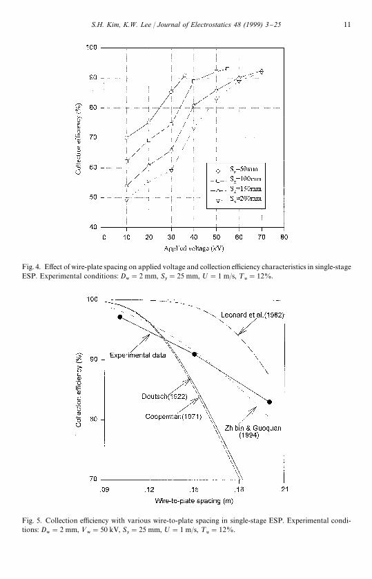
Fig. 4. E!ect of wire-plate spacing on applied voltage and collection e$ciency characteristics in single-stageESP. Experimental conditions: D
8"2 mm, S
y"25 mm, ;"1 m/s, ¹
6"12%.
Fig. 5. Collection e$ciency with various wire-to-plate spacing in single-stage ESP. Experimental condi-tions: D
8"2 mm, <
8"50 kV, S
y"25 mm, ;"1 m/s, ¹
6"12%.
S.H. Kim, K.W. Lee / Journal of Electrostatics 48 (1999) 3}25 11

Fig. 6. E!ect of wire-to-wire spacing and applied voltage on collection e$ciency characteristics insingle-stage ESP. Experimental conditions: D
8"2 mm, S
x"150 mm, ;"1 m/s, ¹
6"12%.
Fig. 7. E!ect of applied voltage and SCA on collection e$ciency characteristics in single-stage ESP.Experimental conditions: D
8"2 mm, S
x"150 mm, S
y"37.5 mm, ¹
6"12%.
12 S.H. Kim, K.W. Lee / Journal of Electrostatics 48 (1999) 3}25

Fig. 8. Comparison of the total e$ciency with the various velocities in single-stage ESP. Experimentalconditions: D
8"2 mm, <
8"50 kV, S
x"150 mm, S
y"37.5 mm, ¹
6"12%.
Fig. 9. E!ects of turbulence intensity on applied voltage and collection e$ciency characteristics insingle-stage ESP. Experimental conditions: D
8"2 mm, S
x"150 mm, S
y"37.5 mm, ;"1 m/s.
S.H. Kim, K.W. Lee / Journal of Electrostatics 48 (1999) 3}25 13

Fig. 10. E!ect of wire diameter on applied voltage and collection e$ciency characteristics in single-stageESP. Experimental conditions: S
x"150 mm, S
y"37.5 mm, ;"1 m/s, ¹
6"12%.
has signi"cant e!ects on the ESP performance. In a given eight wire ESP, thewire-to-wire spacing was maintained at a "xed value, S
y"37.5 mm where the collec-
tion e$ciency is maximum. The speci"c collection are (SCA) de"ned as the ratio of thetotal collection area to the total gas volume #ow rate is an important parameter thatcharacterizes the performance of ESP. In this experiment, the total collection area ofthe plates was "xed. Thus, the SCA value was changed by varying the #ow velocity (1,1.3, 1.6, 2 and 2.5 m/s). As the #ow velocity is increased, the SCA value becomes smalland the collection e$ciency of ESP decreases as shown in Fig. 7. The experimentaldata of the single-stage ESP were also compared with theoretical prediction models asshown in Fig. 8. It is observed that the Zhibin and Guoquan model is in a goodagreement with the experimental data. The particles pass through a turbulenceproducing square mesh grid before entering an ESP. The turbulent #ow "eld can becharacterized by measuring both the mean velocity pro"le;(x, y) and the streamwiseroot mean square turbulent velocity u
3...4.(x, y). Here, the velocity in the x-direction
can be ignored because it is so small compared with the velocity in the y-direction.Two types of mesh grids were designed. They were large mesh (M"12 mm,d8"1.2 mm) and small mesh (M"6 mm, d
8"0.6 mm) where M is the mesh size
and d8
is the diameter of mesh wires. These meshes were installed in front of the ESPtest section providing di!erent turbulence intensities. The measured turbulence inten-sity (¹
6) was 12% without the mesh, 15% with large mesh and 18% with the small
mesh, respectively. As seen in Fig. 9, the collection e$ciency could greatly increase as
14 S.H. Kim, K.W. Lee / Journal of Electrostatics 48 (1999) 3}25
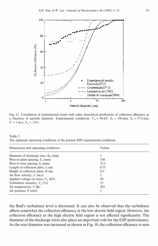
Table 3The optimum operating conditions of the present ESP experimental conditions
Dimensions and operating conditions Values
Diameter of discharge wire, D8
(mm) 1Wire-to-plate spacing, S
x(mm) 150
Wire-to-wire spacing, Sy(mm) 37.5
Length of collection plate, ¸ (m) 0.75Height of collection plate, H (m) 0.3Air #ow velocity, ; (m/s) 1Applied voltage on wires, <
8(kV) 50
Turbulence intensity, ¹6
(%) 15Air temperature, ¹ (K) 293Air pressure, P (atm) 1
Fig. 11. Correlation of experimental result with other theoretical predictions of collection e$ciency asa function of particle diameter. Experimental conditions: <
8"50 kV, S
x"150 mm, S
y"37.5 mm,
;"1 m/s, ¹6"12%.
the #uid's turbulence level is decreased. It can also be observed that the turbulencea!ects somewhat the collection e$ciency at the low electric "eld region. However, thecollection e$ciency at the high electric "eld region is not a!ected signi"cantly. Thediameter of the discharge wires also plays an important role for the ESP performance.As the wire diameter was increased as shown in Fig. 10, the collection e$ciency is seen
S.H. Kim, K.W. Lee / Journal of Electrostatics 48 (1999) 3}25 15

Fig. 12. Collection e$ciency and thickness of deposited #y ash layer as a function of elapsed time.Experimental conditions: D
8"1 mm, S
x"150 mm, S
y"37.5 mm, <
8"50 kV, ;"1 m/s, ¹
6"12%.
to decrease. It is because an increase in the wire diameter leads to higher coronastarting voltages and low electric "eld intensities at the surface of the wire at thecorona onset. For a given applied voltage above the corona starting voltage, thecorona will decrease as the wire diameter is increased. For the same average currentdensity at the collection plate, the space charge density near the wire decreases as thecorona wire diameter is increased. Thus, as the wire diameter is increased to maintainthe average current density at the collection plate, it is necessary to increase theapplied voltage. From these subsequent experiments, the optimum operating condi-tions which can give the highest particle collection e$ciency of ESP are obtained asshown in Table 3. Fig. 11 shows comparison of the experimental results with thecollection e$ciency predicted by the models of Deutsch [1], Cooperman [2], Leonardet al. [3], and Zhibin and Guoquan [7]. This comparison shows that the collectione$ciency measured is higher than that of all the used other models for the particlesize range of 0.1}3 lm. Deutsch [1] and Cooperman [2] did not considernon-ideal parameters such as leakage, particle re-entrainment etc. Even thoughLeonard et al. [3] concentrated on the "nite di!usivity, they could not predictsuccessfully the behavior of small particles. Among the theories considered, the Zhibinand Guoquan [7] model which considered non-uniform gas velocity is again inrelatively good agreement with the present experimental measurement results.
16 S.H. Kim, K.W. Lee / Journal of Electrostatics 48 (1999) 3}25
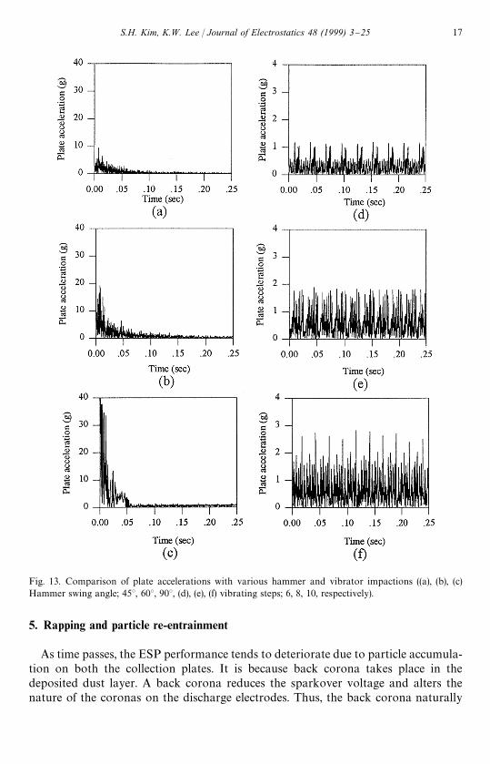
Fig. 13. Comparison of plate accelerations with various hammer and vibrator impactions ((a), (b), (c)Hammer swing angle; 453, 603, 903, (d), (e), (f) vibrating steps; 6, 8, 10, respectively).
5. Rapping and particle re-entrainment
As time passes, the ESP performance tends to deteriorate due to particle accumula-tion on both the collection plates. It is because back corona takes place in thedeposited dust layer. A back corona reduces the sparkover voltage and alters thenature of the coronas on the discharge electrodes. Thus, the back corona naturally
S.H. Kim, K.W. Lee / Journal of Electrostatics 48 (1999) 3}25 17

Fig. 14. Particle size distribution of inlet and outlet dusts for an ESP showing severe re-entrainment andagglomeration of the dust.
impairs performance of an electrostatic precipitator. Fig. 12 illustrates this phe-nomenon. After the elapsed time reaches 300 min, the collection e$ciency is seen tohave decreased to 80% from the initial e$ciency of 95%. To study the e!ects of rap-ping, a rapping system equipped with two hammers plus a vibrator was designedand implemented [17,18]. During the rapping experiments, accelerations of thehammers, the vibrator, and the plates were measured using the dynamic signalanalyzer and the accelerometer. The sensor was attached to the center of the collectionplate. The hammer rapping system is limited to collecting electrode for cleaning ofdry-type horizontal #ow ESP [19]. The mechanism consists of a shaft runninghorizontally across the ESP between banks of collecting plates. The shaft is turned byhands. The hammers are connected to the shaft and then strike against the collectingplates. The rapping intensity was varied by adjusting the angle of the hammer swing. Thehammers impacted the collection plate with a peak acceleration of 400}600 g, where g isa gravitational acceleration (g"9.8 m/s2). Depending on the angle of the hammer swing(45, 60, and 903), the collection plates experienced a peak in-plane acceleration value,G
H(10g, 20g, and 40g) as in Fig. 13 [(a), (b), and (c), respectively]. In the case of
vibrator, electromagnetic vibrators consisted of a balanced, spring-loaded armaturesuspended between two synchronized electro-magnetic coils. When energized, thearmature vibrates at the line frequency. This vibrating energy is transmitted througha rod to the collection plates. In full scale ESPs, this device is used mainly in the
18 S.H. Kim, K.W. Lee / Journal of Electrostatics 48 (1999) 3}25
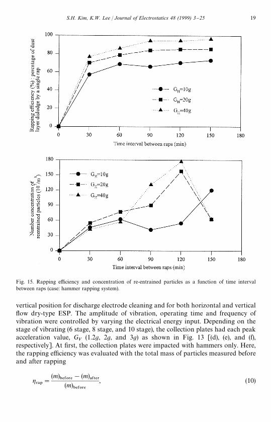
Fig. 15. Rapping e$ciency and concentration of re-entrained particles as a function of time intervalbetween raps (case: hammer rapping system).
vertical position for discharge electrode cleaning and for both horizontal and vertical#ow dry-type ESP. The amplitude of vibration, operating time and frequency ofvibration were controlled by varying the electrical energy input. Depending on thestage of vibrating (6 stage, 8 stage, and 10 stage), the collection plates had each peakacceleration value, G
V(1.2g, 2g, and 3g) as shown in Fig. 13 [(d), (e), and (f),
respectively]. At "rst, the collection plates were impacted with hammers only. Here,the rapping e$ciency was evaluated with the total mass of particles measured beforeand after rapping
g3!1
"
(m)"%&03%
!(m)!&5%3
(m)"%&03%
, (10)
S.H. Kim, K.W. Lee / Journal of Electrostatics 48 (1999) 3}25 19

Fig. 16. Rapping e$ciency and concentration of re-entrained particles as a function of time intervalbetween raps (case: combined rapping system).
where (m)"%&03%
is the total mass of deposited particles before rapping. (m)!&5%3
is the totalmass of deposited particles after rapping.
Concurrently, the particle size distribution was measured at the outlet of ESP tocheck the in#uence of the re-entrained particles. Fig. 14 shows that re-entrainedparticles are larger than the original particles. Obviously, the particles wereaggregated to become compact during deposition. Fig. 15 shows that the rappinge$ciency increased with increasing time interval between raps. It is because thethickness of deposited #y ash layer is increased. In other words, the aggregating forceof deposited particles is su$ciently strong. Thus, if particles are impacted with shearforce provided by the hammer, they would become separated from the collection
20 S.H. Kim, K.W. Lee / Journal of Electrostatics 48 (1999) 3}25
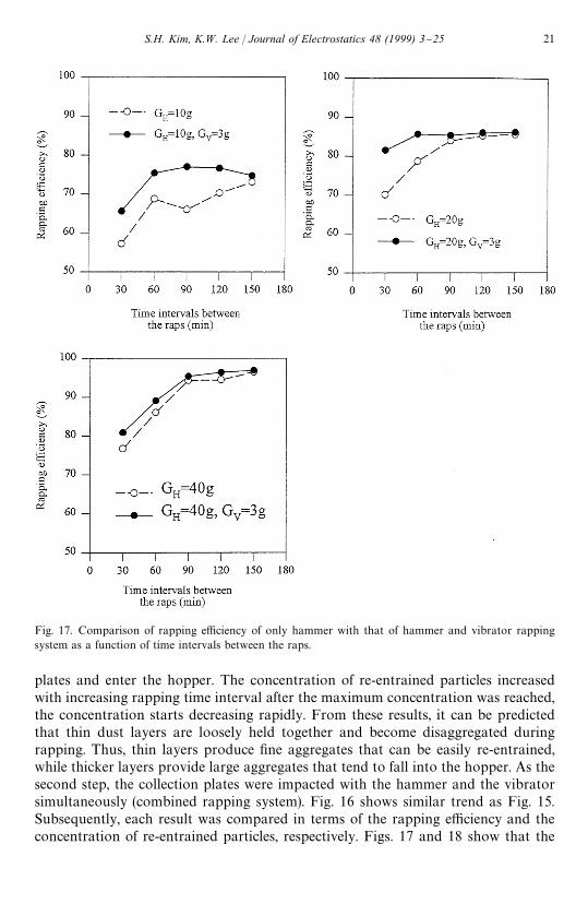
Fig. 17. Comparison of rapping e$ciency of only hammer with that of hammer and vibrator rappingsystem as a function of time intervals between the raps.
plates and enter the hopper. The concentration of re-entrained particles increasedwith increasing rapping time interval after the maximum concentration was reached,the concentration starts decreasing rapidly. From these results, it can be predictedthat thin dust layers are loosely held together and become disaggregated duringrapping. Thus, thin layers produce "ne aggregates that can be easily re-entrained,while thicker layers provide large aggregates that tend to fall into the hopper. As thesecond step, the collection plates were impacted with the hammer and the vibratorsimultaneously (combined rapping system). Fig. 16 shows similar trend as Fig. 15.Subsequently, each result was compared in terms of the rapping e$ciency and theconcentration of re-entrained particles, respectively. Figs. 17 and 18 show that the
S.H. Kim, K.W. Lee / Journal of Electrostatics 48 (1999) 3}25 21

Fig. 18. Comparison of the concentration of re-entrained particles by only hammer rapping with that of re-entrained particles by combined rapping (hammer plus vibrator) as a function of time interval between theraps.
e$ciency of the combined rapping is higher by 2}10% than that of the hammerrapping only. The concentration of re-entrained particles of combined rapping isgenerally much higher than that of only hammer rapping. From this result, it is foundthat unless the rapping system operates at a su$ciently high acceleration, only "neaggregates will be dislodged and re-entrained. Thus, this mechanism can adverselya!ect the performance of electrostatic precipitators. Finally, the optimum operatingcondition which had the combined rapping system (G
H"40g, G
V"3g) and the time
interval between raps (¹*/5"150 min) was applied to the ESP operating for 5 h and
the change of the particle collection e$ciency was measured. As seen in Fig. 19, thecombined rapping system is recommended to keep the higher collection e$ciencyover a long elapsed operating time.
22 S.H. Kim, K.W. Lee / Journal of Electrostatics 48 (1999) 3}25

Fig. 19. E!ect of rapping on collection e$ciency as a function of elapsed time. Experimental conditions:D
8"1 mm, S
x"150 mm, S
y"37.5 mm, <
8"50 kV, ;"1 m/s, ¹
6"12%.
6. Conclusions
In this study, a laboratory-scale eight wire single-stage electrostatic precipitatorwas designed, built, and operated in a wind tunnel. At "rst, the optimum ESPoperating conditions were sought for achieving relatively high collection e$ciency.Secondly, characteristics of the rapping mechanisms were studied by varying di!erentparameters including the thickness of #y ash layer, the magnitude of rapping acceler-ation, the hammer type and the vibrator type. As a result of the present experimentalstudy, the following conclusions can be reached:(1) As the diameter of discharging wires and the wire-to-plate spacing are decreased,
a higher collection e$ciency of ESP is obtained. For cases in which the wire-to-plate spacing is small (S
x(10 mm), theoretical models predict much higher
collection e$ciency than experimentally measured e$ciency. When the wire-to-plate spacing is large (S
x'15 mm), the Deutsch [1] and the Cooperman [2]
S.H. Kim, K.W. Lee / Journal of Electrostatics 48 (1999) 3}25 23

models underestimate the collection e$ciency compared to the experimentaldata. As the wire-to-plate spacing increased, the decreasing trend of experimentalcollection e$ciency is similar to the model of Zhibin and Guoquan [7].
(2) In the multiwire single-stage ESP, there exists an optimum wire-to-wire spacing.In the present experiment, the highest collection e$ciency occurred at S
y"
37.5 mm. Thus, the wire-to-wire spacing proves to be one of the importantvariables for achieving high collection e$ciency with a multiwire single-stageESP.
(3) As the air #ow velocity increases, the overall particle collection e$ciency de-creases. Among the theories used, the Zhibin and Guoquan [7] model was foundto be in a better agreement with the experimental data than the other models.
(4) Turbulence intensity before the precipitating region plays an important role in thelow electric "eld region. However, in the high electric "eld region, particlesdeposit on the collection plates readily regardless of turbulence intensity.
(5) As the thickness of #y ash layer and the acceleration of rapping increase, therapping e$ciency increases. A combined rapping system consisting of hammerplus vibrator is recommended to maximize the rapping e$ciency. Under theexperimental conditions used in this study, a combination G
H"40g for hammer,
GV"3g for vibrator and a time interval between raps of ¹
*/5"150 min, provided
the highest rapping e$ciency.(6) With respect to particle re-entrainment, we con"rmed that the number concentra-
tion of re-entrained particles increased with an increasing elapsed time. Afterreaching the maximum concentration, it decreases rapidly. This is in goodagreement with the observations of Plato [20], Nichols et al. [21].
(7) The particles re-entrained during rapping are generally larger than originalparticles. Apparently, the size increase is due to the aggregating mechanismoperating while particles remain deposited.
References
[1] W. Deutsch, Bewegung und Ladung der Elektrizitastrager im Zylinderkondensator, Ann Phys. 68(1922) 335}344.
[2] G. Cooperman, A new theory of precipitator e$ciency, Atmos. Environ. 5 (1971) 541}551.[3] G.L. Leonard, M. Mitchner, S.A. Self, Experimental study of the e!ect of turbulent di!usion on
precipitator e$ciency, J. Aerosol Sci. 13 (1982) 271}284.[4] K.D. Khim, M. Mitchner, S.A. Self, Comparison of wire-plate and plate-plate electrostatic precipita-
tors in turbulent #ow, J. Electrostat. 19 (1987) 21}32.[5] Z. Zhibin, Z. Guoquan, New model of electrostatic precipitation e$ciency accounting for turbulent
mixing, J. Aerosol Sci. 23 (2) (1992) 115}121.[6] G.A. Kallio, D.E. Stock, Interaction of electrostatic and #uid dynamic "elds in wire-plate electrostatic
precipitators, J. Fluid Mech. 240 (1992) 133}166.[7] Z. Zhibin, Z. Guoquan, Investigations of the collection e$ciency of an electrostatic precipitator with
turbulent e!ects, Aerosol Sci. Technol. 20 (1994) 169}176.[8] H.J. White, Industrial Electrostatic Precipitation, Addison-Wesley, Reading, MA, 1963.[9] N.A. Fuchs, On the stationary charge distribution on aerosol particles in a bipolar ionic atmosphere,
Geo"s. Pure Appl. 56 (1963) 185}193.
24 S.H. Kim, K.W. Lee / Journal of Electrostatics 48 (1999) 3}25
[10] K.H. Yoo et al., Charging and collection of submicron particles in two-stage parallel-plate electro-static precipitators, Aerosol Sci. Technol. 27 (1997) 308}323.
[11] G. Herdan, Small Particle Statics, 2nd ed., Academic Press, New York, 1980.[12] W.T. Sproull, Minimizing rapping loss in precipitators at a 2000-megawatt coal-"red power station, J.
Air Pollu. Control Assoc. 22 (3) (1972) 181}186.[13] H.W. Spencer, Rapping re-entrainment in a nearly full scale pilot electrostatic precipitator, Environ-
mental Protection Agency Publication, EPA-600/2-76-140, 1976.[14] H.W. Spencer, Rapping re-entrainment in a nearly full scale pilot electrostatic precipitator, EPA-
600/2-76-140, 1976.[15] H.W. Spencer, D. Juricic, Electrostatic precipitator plate rapping and reliability, Joy Industrial
Equipment Company, FP-1006, Vol. 3, Part 1, Los Angels, CA, 1980.[16] O.J. Tassicker, Rapping re-entrainment losses in full-scale electrostatic precipitators, Conference and
Course on Electrostatic Precipitation, Leura, NSW, Australia, 1978.[17] J.R. McDonard, A.H. Dean, Electrostatic Precipitator Manual, Noyes Data Corporation, New
Jersey, 1982.[18] S. Oglesby, B. Grady, Electrostatic Precipitation, Marcel Dekker, New York, 1978.[19] J.K. Lee et al., An experimental study of electrostatic precipitator plate rapping and re-entrainment,
Proceedings of Seventh International Conference on Electrostatic Precipitation, Kyongju, Korea,1998, pp. 155}162.
[20] H. Plato, Rapping of collecting plates in electrostatic precipitators, Staub-Reinhalt, Luft 29 (1969)22}30 (in English).
[21] G.B. Nichols, H.W. Spencer, J.D. McCain, Rapping re-entrainment study, Report to Tennessee ValleyAuthority, TVA Agreement TV36921A, November 1975.
S.H. Kim, K.W. Lee / Journal of Electrostatics 48 (1999) 3}25 25