experimental study on vibrations of shafts … study on vibrations of shafts suspended by regular...
TRANSCRIPT
Experimental Study on Vibrations of Shafts Suspended by Regular and Irregular Bore Journal Bearing
E.M.Attia1 A.N .Mohamed2
1Alexandria University- Faculty of Engineering -Department of mechanical engineering, Now on leave in Arab Academy for Science, Technology & Maritime Transport, Faculty of
Engineering, [email protected]
2Alexandria University- Faculty of Engineering -Department of mechanical engineering,
Abstract Practical applications of machine elements supported by a flexible support are rotating shafts mounted on bearings. The bearings in general are journal or rolling which have stiffness and damping characteristics. The shaft itself has hysteric damping due to the deflection and whirling. The problem of journal bearing vibrations is a great importance in whirling of the rotating shafts and it is important to minimize the vibrations acting on that bearings. A very recent method for doing this is the creation of smart journal bearings using irregular surface. This type of surfaces will cause an alteration in the dynamic properties of the journal bearing and thus the dynamic performance of the rotating shaft. This paper introduces an experimental model of whirling flexible shaft carrying a load at a mid-point and is supported by two identical journal bearings at its ends. Two types of journal bearings are fabricated, the first one its bore was made from regular surface and the second its bore was made from irregular surface. The analysis here is based on measuring the vibrations in the presence of regular and irregular bore journal bearing. Hammering and run - up test was made and analyzed for the two cases. Also effect of changing speed and load acting on each bearing was studied experimentally. An overall vibration is measured for different loads and the results were compared as the shaft is mounted by regular bore bearing or irregular type. Keywords: Journal Bearings, Regular, Irregular, Vibrations, Dynamic, Measurements. 1 Introduction Study the effect of bearing surface texture on the bearing performance and loads is an effective approach for the optimization of the bearing. It helps in effective lubrication and thus it optimizes the bearing performance. Anno et al. [1] studied the performance of journal bearing with asperity surface. Deterministic micro-asperities were of a prescribed shape, size, orientation and distribution that compromise an engineered surface texture. The asperities can be made from robust materials including metal, ceramics and plastic, making them ideal for a wide variety of bearing and sealing applications. Krodkicwski et al [2] presented the modeling and analysis of a rotor-bearing system with a type of active oil bearing. The active bearing was supplied with a flexible sleeve whose deformation may be changed during operation of the rotor. The results showed that within a large region of configuration parameters of the rotor-bearing system, the self-excited vibration may be eliminated or reduced during operation by properly controlled deformation of the flexible sleeve and
optimal choice of the hydrodynamic damper parameter. Fujita et al. [3] examined the stability analysis of hydrodynamic journal bearings using the nonlinear equations of motion. The nonlinear fluid forces in radial and tangential directions were obtained and the stability of journal by the numerical simulation on vibration behavior of journal was investigated. Girish et al.[4] introduced an approach to predict the unbalance by driving a mathematical model for vibrations based prognosis for effect of unbalance on journal bearing and also discussed the effect of unbalance on journal bearing. Ravinder and Lyndon [5] presented a numerical study of the effect of different shapes of deterministic micro-asperities in sliding-surface-lubrication with circular, square, diamond, hexagonal and triangular cross-sections of particular shape .Ighil et al. [6] introduced a comparative study of the hydrodynamic effects of a few deterministic texture shapes in a journal bearing application. The geometry and the size of textures affect load capacity and friction torque. The
WSEAS TRANSACTIONS on APPLIED and THEORETICAL MECHANICS E. M. Attia, A. N. Mohamed
E-ISSN: 2224-3429 8 Volume 11, 2016
parallelepiped textures showed advantages compared to the other geometries for the improvement of the performances of the bearing. Peng HE et al. [7] provided a comprehensive analysis of misaligned journal bearings based on two different mass-conservative models which appropriately took into account film rupture and reformation.The results showed that cavitation has great effect on bearing performances, especially when the surface roughness is large. Therefore, it is necessary to consider the effects of journal misalignment alongside inter-asperity cavitation theory in the design and analysis of journal bearings. Mehta et al. [8] presented the stability analysis of a two lobe hydrodynamic bearing operating with couple stress fluids that has been solved using the finite element method. A non-dimensional parameter has been used to indicate the length of the long chain polymer added to the bulk Newtonian fluid. Kamal [9] studied the stability problem of vibrating rotors supported by hydrodynamic journal bearing with interval parameters. The considered vibrating system is modeled such that the oil film coefficients are intervals rather than single-valued quantities. An interval analysis technique is applied to evaluate the stability of the system. Mancilla et al. [10] introduced a new closed-form expression for calculating the linear stability thresholds for rigid and flexible Jeffcott systems and the imbalance response for a rotor supported on a hybrid bearing. Using the roto-dynamic into the expression for the corresponding velocity thresholds and imbalance response, the system stability and vibration performances are estimated and analyzed. Abdo et al. [11] investigated the dynamic behavior of the plain cylindrical journal bearing having three-dimensional asperity shell (liner). For a given asperity model, asperity height, surface asperity pattern (geometry factor) and density of the asperities are the parameters introduced to control the shape of the three-dimensional asperity in the bearing liner. Nacer et al. [12] examined the texture location influence on the hydrodynamic journal bearing performance. A numerical modelling was used to analyze the cylindrical texture shape effect on the characteristics of a hydrodynamic journal bearing. The theoretical results showed that the most important characteristics can be improved through an appropriate arrangement of the textured area on the contact surface. Ighil [13] introduced a numerical approach in the analysis of texture effects on bearing characteristics. Modeling and understanding the evolution of journal-bearing characteristics with textures was studied. A rigorous
methodology was recommended. The work was divided into two steps. The first one serves to quantify the evolution of the characteristics with the texture parameters and to deduce their optimized values. The second step enhances the performance of the journal bearing by progressively taking into account the optimized values of texture parameters. Rong [14] studied the steady state hydrodynamic lubrication of journal bearings with three-dimensional asperities. The numerical procedure used incorporates a cavitation algorithm, which automatically predicts film rupture and reformation in the bearings. Numerical simulation results showed that the pressure distribution caused by an asperity depends not only on asperity height but also on asperity dimensions. Singh and Sharma [15] studied the improvements in different shapes of textures on journal at different location of texture zone which was reported to have significance influence on the bearing performance. Different types of surface roughness (texturing) has been proposed and evaluated for this purpose. Ishida, Y., and Liu, J [16] introduced a new vibration suppression method utilizing a discontinuous spring by using additional springs with preload. This method is effective for nonstationary vibration. The characteristics of the vibration suppression were demonstrated theoretically and experimentally. A. Chasalevris and F. Dohnal, A [17] investigated the development of a journal bearing with variable geometry. The journal bearing with variable geometry is presented in this work in its final form with the detailed design procedure. The current journal bearing was constructed in order to be applied in a simple real rotor bearing system that already exists as an experimental facility. A. Chasalevris and F. Dohnal [18] introduced a variable geometry journal bearing (VGJB), recently patented, is applied for the mounting of a large scale rotor bearing system operating at the range of medium speed. The simulation of the rotor bearing system incorporates a recent method for simulation of a multi-segment continuous rotor in combination with nonlinear bearing forces. The aim of the present work is, constructing an experimental model for a shaft supported at each end by a journal bearing. Two types of bearings are manufactured, the first one its bore surface is regular and the second its bore surface is irregular. Hammering and run - up test was made and analyzed for the two cases. Also effect of changing speed and load acting on each bearing was studied experimentally. The overall vibrations are measured for different loads and the results were compared as
WSEAS TRANSACTIONS on APPLIED and THEORETICAL MECHANICS E. M. Attia, A. N. Mohamed
E-ISSN: 2224-3429 9 Volume 11, 2016
the shaft is mounted by regular bore bearing or irregular type. 2 Experimental model constructions The experimental model is constructed from many mechanical and hydraulic elements as shown in Fig.1, 2 and these elements can be classified as the following, 2.1. Electric motor An electric motor is used with power 5 hp and its speed (n) is variable with a maximum value of 3000 rpm. 2.2. Journal bearings The journal bearing is manufactured from two half’s of sleeve and a cover which is fixed to the base. The bearing is constructed from two layers. The outer layer is made from cast iron to increase the damping and decrease the vibrations acting on the bearing.
The inner layer is made from soft metal in older to avoid the wear of the shaft .The inner diameter and length of the bearing is taken to be 47 mm and 23.5 mm respectively, thus the ratio between the bearing length and its diameter is (L/D = 0.5). The radial clearance of the bearing is set up to be 0.05mm. Also an axial groove is made to feed the oil through the radial clearance between the shaft and the sleeve. A hydraulic circuit (see Fig.2) is constructed for feeding the oil inside the bearing and its components are, oil tank, gear pump, relief valve, oil cooler, temperature and pressure gauges. The lubrication of bearing is realized by pushing oil inside the bearing using a gear pump which is derived by an electric motor and the output flow of pump is derived with a pressure of 0.5 bar for each bearing. The oil used inside the bearing is Mobil type and its viscosity is 0.03 Pa.s at a temperature of 400.
Motor
Coupling
Gauge temperature
Journal Bearing Gauge
Pressure Rotating Disc
Fig. 1: Main components of dynamic model
WSEAS TRANSACTIONS on APPLIED and THEORETICAL MECHANICS E. M. Attia, A. N. Mohamed
E-ISSN: 2224-3429 10 Volume 11, 2016

2.3 Irregular surface formulation The irregular surface of bore bearing is formed by using a lathe with a cutting pen and the depth of cut is equal to the width and its value is 0.25 mm. Density of irregular surface depends on the number of asperities formed in the surface and the shape of asperities pattern is clear by Fig.3. 2.4. Shaft and load acting on journal bearing The shaft is made from mild steel and is formed by using a lathe with diameter of 47 mm and length of
750 mm. The weight of the shaft is 100 N. A flanged coupling is used to connect the shaft and electric motor. The shaft is supported by two journal bearings and an (Easy – Laser Alignment) is used to achieve the alignment of the shaft. A flat disc is fixed at a midpoint of the shaft and its weight can be changed by using a multiple half’s discs which is secured to the flat disc as shown in Fig. 1 and 2. The load acting on each bearing (W) is represented by ½ (weight fixed to the shaft + weight of shaft itself).
Fig. 4: Main components of hammering test
Fig.3: Journal bearing components and shape of irregular surface
Fig.2: Main components of hydraulic circuit
Input oil
Output oil
Gauge temperature
Oil tank
WSEAS TRANSACTIONS on APPLIED and THEORETICAL MECHANICS E. M. Attia, A. N. Mohamed
E-ISSN: 2224-3429 11 Volume 11, 2016

Fig.6 : Model form used for vibrations measurements
Fig.5. Easy – Laser Alignment system
2.5. Vibrations measurement devices The devices of measuring the vibrations used in this work is, hammer, accelerometer, pulse device, tachometer, analyzer and Easy –Laser Alignment system. Figs.4, 5 and 6 show some of the devices used for measuring the vibrations level.
3 Experimental setup The load acting on each bearing is changed in each experiment to be (W=50 N, 87.5 N, 107.5 N, 126 N and 145.5 N). This is done as the shaft is supported by a journal bearing its internal surface is regular and then the bearing is replaced by another type its bore is irregular shape. The steps of each experiment is summarized as the following, 1-Hammering test for each load is performed in which coherence number, phase angle and frequency response is measured. 2- Run up test for each load is performed as the speed of shaft is changed from 600 to 3000 rpm with step change of 100 rpm.
3-The measured and recorded diagrams during run –up test are classified to be, water fall diagram, vibrations velocity, phase angle and auto spectrum (Fast Fourier Transform -FFT). 4- Overall vibrations is measured for different loads and speeds by using the analyzer. Since the number of graphs obtained from the experimental results is large, so a sample of these graphs is introduced in this paper. 3.1 Hammering test, load of each bearing is 50 N Indication of resonance frequencies is important for any machine .The machine must run with a speed far away from that frequency in order to avoid high vibrations level. If the turning speed goes with the machine's resonance frequency, the speed in this case is a critical speed. The hammering test is important to indicate the resonance frequencies of the machine. The hammer and probe are connected to the pulse device and the device is turned on after setting the connection, in addition the program of measuring the vibrations is also ready to record the results. Coherence function β is defined as a measure of the noise present in the signals. The value of this function is between one and zero, and is a measuring of the degree of linearity between two related signals, such as the input force to the structure and the vibration response. Usually β =1 near the natural frequency of the system because the signals are large and are less influenced by the noise. Fig. 7 shows the relation between frequency and coherence number when the shaft is supported by regular bore bearings and load acting on each bearing is 50 N. As the value of coherence number is unity, this indication for accuracy of vibrations measurement, since the noise is ignored from the system.
Fig. 7: Coherence number versus frequency - regular bore bearing - W=50N
Frequency (HZ)
Coh
eren
ce n
umbe
r
WSEAS TRANSACTIONS on APPLIED and THEORETICAL MECHANICS E. M. Attia, A. N. Mohamed
E-ISSN: 2224-3429 12 Volume 11, 2016

Fig.9 : Frequency response of hammering test –regular bore bearing - W=50N
Frequency (HZ)
Res
pons
e (m
m/s
2 )/N
The phase angle and corresponding frequency is recorded from hammering test as illustrated by Fig 8. When the phase shifts by 90 degrees, the frequency at which it occurs is a natural frequency (Fig.9). Also Fig. 9 covers the relation between frequency and hammering response (acceleration/force). It is found from this figure that, the first resonance frequency is indicated as 280 Hz (point a). With this information, we can create operating condition shapes to visualize the vibrating system.
3.2 Run up test - Load of each bearing is 50 N A common way to identify resonance empirically is to operate the equipment across its range of operating speeds while measuring the vibration it exhibits. Run-up tests, which monitor vibration from standstill to maximum speed, are a quick way to see if troublesome resonance is present in the system.
The run-up test is a collection of amplitude readings over a changing speed range. Some of the setup information will depend upon how long the run up will occur. It can be anywhere from a few minutes to a few hours. At the beginning of this test, the device is set at first speed and its value 600 rpm. The speed of shaft is measured by using a tachometer. The velocity of vibrations is measured as the speed increases with a step of 100 rpm and the maximum speed is 3000 rpm.
Fig.10 shows a waterfall graph obtained from vibrations of the system during running the shaft. This figure observes frequency as order of rpm in x-axis. The y-axis displays the amplitude of vibrations velocity and z-axis displays the speed.
Also Fig, 11 deals with the amplitude of velocity during run –up test and its recorded value varies from 0.1 mm/s to 1.2 mm/s as the speed of shaft is changed from 600 rpm to 28oo rpm.
Frequency (order of rpm)
Fig. 10 : Water fall diagram - regular bore bearing - W=50N
Vel
ocity
mm
/s
Fig. 8: Phase angle versus frequency - regular bore bearing - W=50N
Frequency (HZ)
Phas
e an
gle
(deg
.)
WSEAS TRANSACTIONS on APPLIED and THEORETICAL MECHANICS E. M. Attia, A. N. Mohamed
E-ISSN: 2224-3429 13 Volume 11, 2016

Frequency (Hz)
Fig. 13: Spectrum FFT diagram - regular bore bearing - W=50N
V
eloc
ity (m
m/s
)
Fig. 15 Coherence number versus frequency- irregular bore bearing - W= 126 N
Frequency (Hz)
Coh
eren
ce n
umbe
r
The variation in phase angle during run up test is illustrated by figure 12. It is found from this figure that, the phase angle fluctuates about -1500
as the speed of shaft is changed from 600 to 2800 rpm. Figures 13 demonstrates the measured Auto- Spectrum (FFT), as the shaft rotates at (n= 1100 rpm). 3.3 Hammering test - Load of each bearing 126 N Hammering test is provided for two cases, the first one, when the shaft is supported by regular bore bearing and the second case when the shaft is supported by irregular bore bearing. Figs 14 and 15 show the relation between coherence number and frequency for mentioned two cases. At the end of experiment the cursor moves to indicate a unity value of coherence number at which there is no noises during the measured of other parameters such as the indicated resonance frequencies.
Fig.11: Response of run- up test - regular bore bearing W=50N
Speed (rpm)
Vel
ocity
(mm
/s)
Speed (rpm) Fig. 12: Phase angle of run –up test - regular
bore bearing, W=50N
Phas
e an
gle
(deg
.)
Fig. 14: Coherence number versus frequency- regular bore bearing - W=126N
Frequency (Hz)
Coh
eren
ce n
umbe
r
WSEAS TRANSACTIONS on APPLIED and THEORETICAL MECHANICS E. M. Attia, A. N. Mohamed
E-ISSN: 2224-3429 14 Volume 11, 2016

Fig.17: Phase angle versus frequency- irregular bore bearing - W=126N
Frequency (Hz)
Phas
e an
gle
(deg
.)
Figs 16 and 17 show a graph of phase angle during a hammering test. The angle is indicated related to a unity coherence number and its value at first resonance frequency ( point a ) is -23.3 degree when the shaft is supported by regular bore bearing and -42.8 degree ( point b) as the irregular bore bearing was used for supporting the shaft. The frequency response (acceleration/force) of hammering test as the regular bore bearing is used is seen by Figs. 18. It is found from this figure that, the first resonance frequency appears at a frequency of 246 Hz (point a).
When the same experiment is repeated again and the shaft is supported by irregular bore bearing (see Fig.19), it is found that, first resonance frequency is indicated at 200 Hz (point b). Comparing the results of these figures, we can conclude that, in practical applications, using regular bore bearing is better for very high speeds of rotating shafts, since the first resonance frequency is far away from the operating speed.
Fig.16: Phase angle versus frequency- regular bore bearing - W=126N
Frequency (Hz)
Phas
e an
gle
(deg
.)
Fig.19: Frequency response of hammering test- irregular bearing -W=126N
Frequency (Hz.)
Res
pons
e (m
m/s
2 )
Frequency (Hz)
Res
pons
e (m
m/s
2 ) / N
Fig.18: Frequency response of hammering test –regular bore bearing (W=126 N)
WSEAS TRANSACTIONS on APPLIED and THEORETICAL MECHANICS E. M. Attia, A. N. Mohamed
E-ISSN: 2224-3429 15 Volume 11, 2016

Fig. 21: Water fall diagram - irregular bore bearing - W=126N
Frequency (order of rpm)
Vel
ocity
(mm
/s)
3-4 Run up test- load of each bearing is 126 N The water fall graph is indicated as the rotating speed of shaft changes from 600 to 3000 rpm with step of 100 rpm. Fig. 20 shows a water fall diagram when the regular bore bearings is used for supporting the shaft at each end, while Fig. 21 illustrates the same diagram as the irregular bore bearing is used. Also Fig. 22 indicates the amplitude of vibrations velocity during run up test as the shaft is supported by regular bore bearing. It is seen from these figures that, the amplitude of velocity response varies from 0.1 mm/s to 4.2 mm/s as the speed of shaft changes from 600 rpm to 2800 rpm.
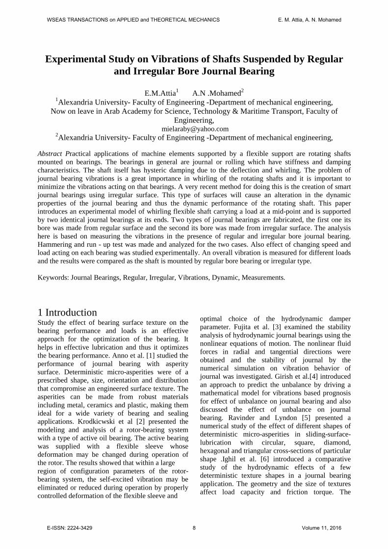
When regular bore bearing is replaced by irregular type and the experiment is repeated again it is found that , the response varies from 0.1 to 3 mm/s as the speed is changed from 600 to 2800 rpm as shown in Fig.23. By comparing the two figures it can be concluded that, using irregular inner surface for journal bearings is better to minimize the vibrations level acting on the support during the shaft rotation. Figs. 24 and 25 shows the variation in the measured phase angle during run-up test .The phase angle is changed from -85.70 to -130.70 for regular bore bearing ,while its value changes from -69.20 to -92.3 0 for irregular bore bearing .
Fig. 20: Water fall diagram- regular bore bearing -W=126N
Frequency (order of rpm)
Vel
ocity
(mm
/s)
Fig.23: Response of run-up test -irregular bore bearing - W=126 N
Speed (rpm)
Vel
ocity
(mm
/s))
Fig.22: Response of run-up test - regular bore bearing - W=126 N
Vel
ocity
(mm
/s)
Speed (rpm)
WSEAS TRANSACTIONS on APPLIED and THEORETICAL MECHANICS E. M. Attia, A. N. Mohamed
E-ISSN: 2224-3429 16 Volume 11, 2016
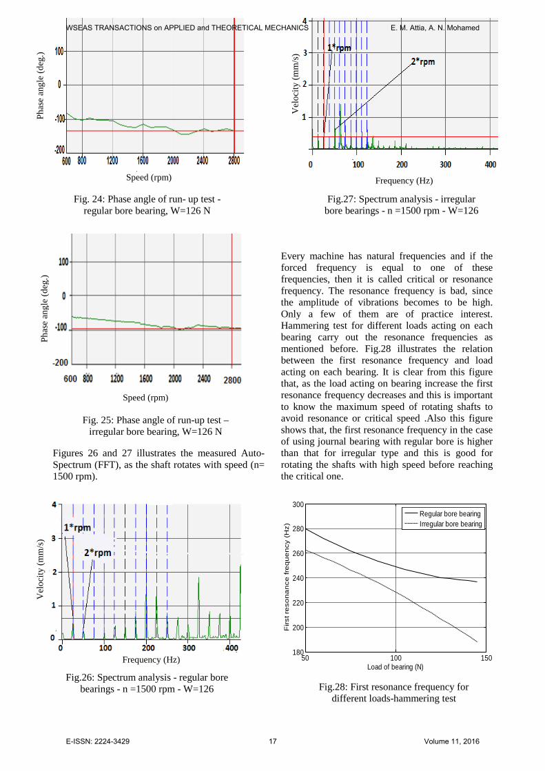
Fig.28: First resonance frequency for different loads-hammering test
50 100 150180
200
220
240
260
280
300
Load of bearing (N)
Firs
t re
son
an
ce fr
eq
ue
ncy
(H
z)
Regular bore bearing Irregular bore bearing
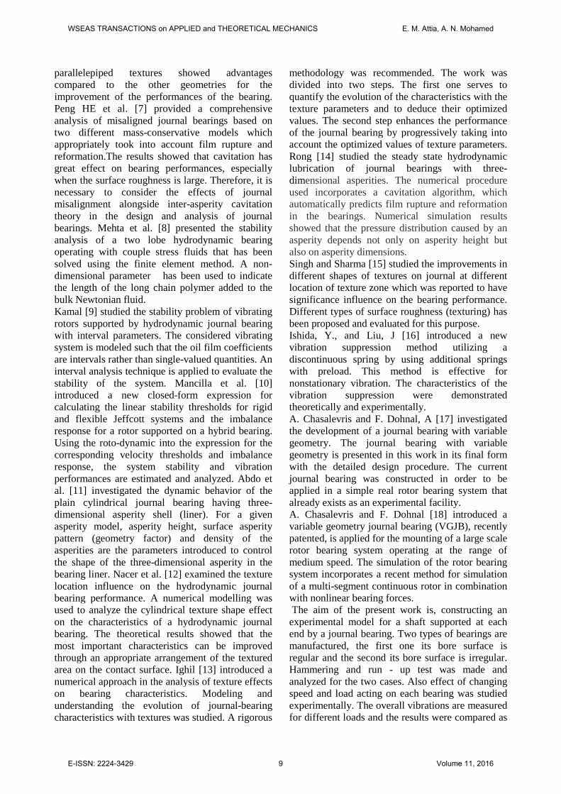
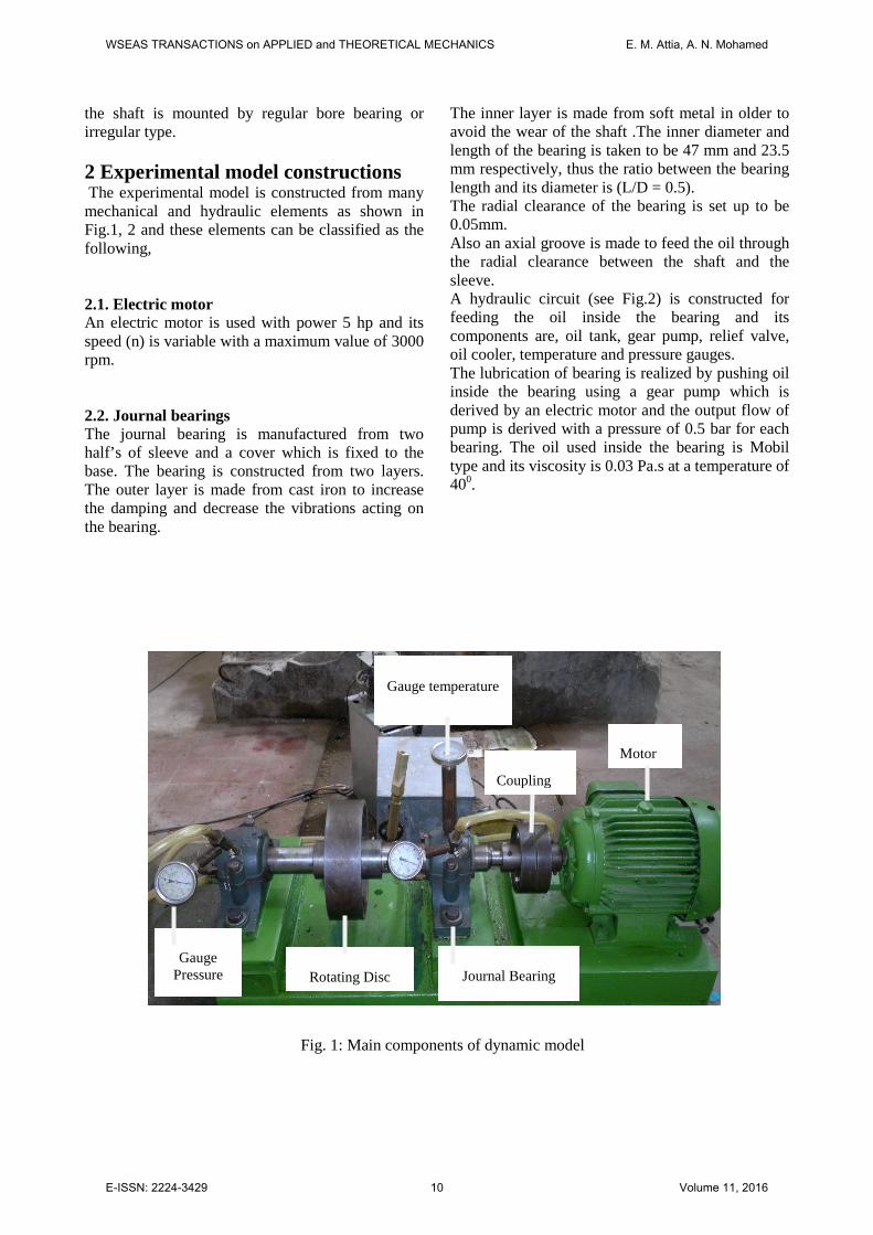
Figures 26 and 27 illustrates the measured Auto- Spectrum (FFT), as the shaft rotates with speed (n= 1500 rpm).
Every machine has natural frequencies and if the forced frequency is equal to one of these frequencies, then it is called critical or resonance frequency. The resonance frequency is bad, since the amplitude of vibrations becomes to be high. Only a few of them are of practice interest. Hammering test for different loads acting on each bearing carry out the resonance frequencies as mentioned before. Fig.28 illustrates the relation between the first resonance frequency and load acting on each bearing. It is clear from this figure that, as the load acting on bearing increase the first resonance frequency decreases and this is important to know the maximum speed of rotating shafts to avoid resonance or critical speed .Also this figure shows that, the first resonance frequency in the case of using journal bearing with regular bore is higher than that for irregular type and this is good for rotating the shafts with high speed before reaching the critical one.
Frequency (Hz)
Vel
ocity
(mm
/s)
Fig.26: Spectrum analysis - regular bore bearings - n =1500 rpm - W=126
Fig. 24: Phase angle of run- up test - regular bore bearing, W=126 N
Speed (rpm)
Phas
e an
gle
(deg
.)
Fig. 25: Phase angle of run-up test – irregular bore bearing, W=126 N
Speed (rpm)
Phas
e an
gle
(deg
.)
Vel
ocity
(mm
/s)
Frequency (Hz)
Fig.27: Spectrum analysis - irregular bore bearings - n =1500 rpm - W=126
WSEAS TRANSACTIONS on APPLIED and THEORETICAL MECHANICS E. M. Attia, A. N. Mohamed
E-ISSN: 2224-3429 17 Volume 11, 2016

Fig.30: Overall vibrations response versus speed and load- regular bore
bearing
Fig.31: Overall vibrations response versus speed and load- irregular bore bearing
A comparison between using regular bore bearing and irregular type during run-up test is seen by Fig.29.This figure indicates the vibrations amplitude as the shaft rotates at 2800 rpm and the load acting on each bearing is changed from 50 to 145.5 N. Also this figure illustrates that, using irregular bore for journal bearing is good to reduce the amplitude of vibrations during the rotation of shaft especially for low loads. 4 Overall vibrations Overall vibrations is measured by an analyzer and its reading gives a vibrations value which cover most frequencies produced from the machine . Overall vibrations velocity is measured for different loads acting on bearing as mentioned before. The measurements are divided into two steps, the first one, when the shaft is suspended by regular bore journal bearing and the second step, when the bearing is changed to be irregular type. The relation between speed of shaft and overall vibrations for different loads of regular bore bearing is clear by Fig. 30.
Also Fig. 31 demonstrates variation of overall response for different speed and loads but for irregular bore bearing. Table 1 illustrates a comparison between overall vibrations in the presence and absence of irregular surface for journal bearing (W= 87.5 N).
Table 1. Vibrations response for regular and irregular bore bearing W=87.5 N
Speed (rpm)
Response Regular bore bearing
(mm/s)
Response Irregular bore
bearing (mm/s)
200 0.0302 0.0197 300 0.0271 0.0168 400 0.0333 0.0221 600 0.0579 0.0318 800 0.0565 0.0317 1000 0.0996 0.0489 1300 0.1309 0.0619 1700 0.2045 0.0891 2000 0.3452 0.1169 2300 0.5378 0.1868 2600 1.009 0.4278 2700 1.187 0.5231 2900 1.628 0.7291 3000 1.959 0.7956
50 100 1501
1.5
2
2.5
3
3.5
4
4.5
Load (N)
Vib
ratio
ns a
mpl
itude
(mm
/s)
Regular bore bearings Irregular bore bearings
Fig.29: Vibrations amplitude-run up test n= 2800 rpm
WSEAS TRANSACTIONS on APPLIED and THEORETICAL MECHANICS E. M. Attia, A. N. Mohamed
E-ISSN: 2224-3429 18 Volume 11, 2016

Comparing the results of these figures it is found that, the overall vibrations in the presence of irregular bore journal bearing is less than that for regular type. Also these figures show that, the difference between the responses in the two cases increases as the speed of rotating shaft increases. Using irregular surface for journal bearing minimize the vibrations amplitude by 50 % .Also the load acting on the bearing is a main factor for changing the response since as the load increases the overall vibrations increases. Fig. 32 represents the relation between the load acting on bearing and the response difference in the case of using regular surface and irregular type for journal bearing. It is found from this figure that, the difference in vibrations amplitude changes from 0.1 mm/s to 6.5 mm /s as the speed varies from 1000 rpm to 3000 rpm while the load acting on the bearing is 145.5 N .Also this figure demonstrates that the difference in amplitude at low speeds (1000 rpm or less) can be neglected irrespective of bearing load .In addition to this results, as the bearing load increases the difference between the amplitude increases. A graph of phase angle for different speeds of shaft and bearing loads is illustrated by Figs.33 and 34. These graphs are indicated from the measurements of phase angles during run up test as the shaft is supported by regular and irregular bore bearing respectively.
5 Conclusion A model of rotating shaft carrying a rotating load at a mid-point is manufactured. A journal bearing having a regular and irregular bore was fabricated and was used for supporting the shaft at each end. Also a hydraulic circuit with pressure and temperature sensors is constructed for feeding the oil inside the bearing. Vibrations measurements is analyzed for the model as the regular and irregular bore journal bearing was used and the load acting on each bearing is changed.
Fig.33: Phase angle during run-up test- regular bore bearing
Fig.34: Phase angle during run-up test- irregular bore bearing
80 90 100 110 120 130 140 1500
1
2
3
4
5
6
7
Journal bearing load (N)
Ove
rall
vibr
atio
ns d
iffer
ence
(mm
)
n=1000 rpmn=1500 rpmn=2000 rpmn=2500 rpm n=3000 rpm
Fig.32: Effect of load on overall vibrations response difference
Ove
rall
vibr
atio
ns d
iffer
ence
(mm
/s)
WSEAS TRANSACTIONS on APPLIED and THEORETICAL MECHANICS E. M. Attia, A. N. Mohamed
E-ISSN: 2224-3429 19 Volume 11, 2016

The experimental results also demonstrated the importance of using irregular surface for bore of journal bearings. From vibrations analysis we can conclude the following: 1- Vibrations level acting on shaft support depends on the load acting on the journal bearing irrespective of the shape of its bore. As the load increases the amplitude of vibrations increases especially for high speed of rotating shaft while at low speed, changing the load has no effect. 2- The irregular bore of journal bearing minimizes the overall vibrations acting on rotating shafts for different speeds. 3- Resonance frequencies are dependent on bore shape of journal bearing, since irregular shape minimizes the resonance frequencies. So it is better to use regular bore bearings for very high rotating speed of the shaft. 4- The irregular bore of journal bearing minimizes the vibrations level during run-up of rotating shafts. 5-The difference between vibrations level for the case of using regular and irregular bore bearing increases as the load and speed of shaft increases but the effect of load diminishes at low speed. References [1] Anno J.N., Walwit J.A., and Allen C.M. (1969).
Load Support and Leakage from Micro Asperity Lubricated Face Seals. ASME Journal Lubrication Technology, pp. 726 -731
[2] Krodkiewski J.M., Cen, Y and Sun L (1997).Improvement of Stability of Rotor System by Introducing a Hydrodynamic Damper into Active Journal Bearings. International Journal of Rotating Machinery, Vol. 3 No. 1, pp. 45-52,
[3] FujitaK., Shintani A.and Yoshioka K. (2000).Simulation Study on Vibrations Behavior of Fluid Journal Bearings with Incompressible Fluids. Proceeding of the 7th International Conference on Flow-Induced Vibration, FIV, Lucerne, Switzerland, 19-22 June,
[4] Girish D. Mehta, Vijaykumar S. Shende, Prerna. S.Borkar A. (2013). Mathematical Model for Vibration Based Prognosis for Effect of Unbalance on Journal Bearing. IJERA, Vol. 3, Issue 1, pp.537-544.
[5] Ravinder B. Siripuram and Lyndon S. Stephens, (2004). Effect of Deterministic
Asperity Geometry on Hydrodynamic Lubrication. Journal of Tribology, Transaction of the ASME, Vol.126, pp.527-533.
[6] Ighil N.T., P. Maspeyrot, M. Fillon and A. Bounif (2007).
Hydrodynamic Effects of
Texture Geometries on Journal Bearing Surfaces. 10th International Conference of Tribology, pp.8-10, November,
[7] Zhen-peng He, Jun-hong Zhang, Zhou-yu Li, Lin Ba, Gui-chang Zhang, Kai-nan Wang, Xing Lu ,(2013). Inter-Asperity Cavitation for Misalignment Journal Lubrication Problem Based on Mass Conservative Algorithm. Journal of Zhejiang University-Science A, Applied Physics and Engineering, Vol.14, No.9, pp: 642-656,
[8] Mehta N.P, Rattan S.S. and Rajiv Verma, (2010). Stability Analysis of two Lobe Hydrodynamic Journal Bearings with Couple Stress Lubricant. ARPN Journal of Engineering and Applied Sciences, Vol.5 No.1 January
[9] Kamal A.F. Mustafa, (1999).Stability of Journal Bearing – Rotor Systems with Interval Bearings Parameters. Journal of Vibration and Control, November, Vol.,5 No.6, pp.941-953
[10] MancillaJ.G.,Valeri Nosov and Nararo G.S. (2005).Rotor–Bearing System Stability Performance Comparing Hybrid versus Conventional Bearings. International Journal of Rotating Machinery, Vol.1 pp. 16-22,
[11] Khalead M Abdou , E.M. Attia , E. Saber (2010) ,Effect of Three-Dimensional Surface Irregularities on the Dynamic Stability of Finite Hydrodynamic Journal Bearings. European Journal of Scientific Research, Vol.46 No.1 pp.036-047.
[12] Nacer Tala-Ighil , Michel Fillon , Patrick Maspeyrot (2011). Effect of textured area on the Performances of a hydrodynamic journal bearing. Tribology International - Vol. 44, No. 3, pp. 211-219,
[13] N. Tala-Ighil , P. Maspeyrot , M. Fillon , A. Bounif (2007).Effects of Surface Texture on Journal- Bearing Characteristics under steady-state operating Conditions. Proceedings of the Institution of Mechanical Engineers, Part J:
WSEAS TRANSACTIONS on APPLIED and THEORETICAL MECHANICS E. M. Attia, A. N. Mohamed
E-ISSN: 2224-3429 20 Volume 11, 2016
Journal of Engineering Tribology, Vol. 221 No. 6, 623-633,
[14] Lin Tsann - ong (1994). Steady State Performance of Finite Hydrodynamic Journal Bearing with Three dimensional Irregularities. Vol. 176, No. 1, pp. 95– 102
[15] Singh P.and Sharma N. (2014). Optimum Design of Journal Bearing Through Surface Texturing- a Review .International Journal of Research in Advent Technology, Vol.2, Issue 1, January pp.428-431
[16] Ishida, Y., and Liu ,J.,(2008).Vibration Suppression of Rotating Machinery Utilizing Discontinuous Spring Characteristics. ASME J.Vibr Acoust., 130 (3), p. 03100
[17] A. Chasalevris and F. Dohnal, (2015). A Journal Bearing with Variable Geometry for the Suppression of Vibrations in Rotating Shafts: Simulation, Design, Construction and Experiment Mechanical Systems and Signal Processing, 52-53, pp. 506
[18] A. Chasalevris and F. Dohnal, (2014). Vibration Quenching in a Large Scale Rotor-Bearing System Using Journal Bearings with Variable Geometry. Journal of Sound and Vibration, 333 (7), pp. 2087-2099
WSEAS TRANSACTIONS on APPLIED and THEORETICAL MECHANICS E. M. Attia, A. N. Mohamed
E-ISSN: 2224-3429 21 Volume 11, 2016