experimental tools in physics: electrostatic accelerators jan pallon€¦ · ·...
TRANSCRIPT
2012-11-28 Electrostatic Accelerators Experimental tools in Physics
Experimental tools in Physics:Electrostatic Accelerators
Jan Pallon
• High vacuum• Ion sources• High Voltage generation• Beam optical components• Radiation Protection

•Atmosphere: 1013 mbar (=760 torr [ mm/Hg] )
•Low vacuum: >10-2 – 10-3 mbar•High vacuum: between 10-3 and 10-8 mbar•Ultrahigh vacuum: <10-8 mbar
•Above 10-2 – 10-3 mbar: Viscous flow•Below 10-2 – 10-3 mbar: Molecular flow
2012-11-28 Electrostatic Accelerators Experimental tools in Physics
Vacuum

Designing a vacuum system• Low vacuum: The gas behaves like a liquid. Narrow pipes OK!
Viscous conductivity for a pipe:CV=(180.D4/L).Pav CV: conductivity in l/s
D: Diameter of pipe in cmL: Length of pipe in cmPav: average pressure in torr
• High vacuum: Wide openings required!!!– Molecular conductivity for a pipe:
Cpipe=11.6.A/(1+L/D) Cpipe : conductivity in l/sA: crossection area of pipe in cm2
L: : Length of pipe in cmD: Diameter of pipe in cm
2012-11-28 Electrostatic Accelerators Experimental tools in Physics
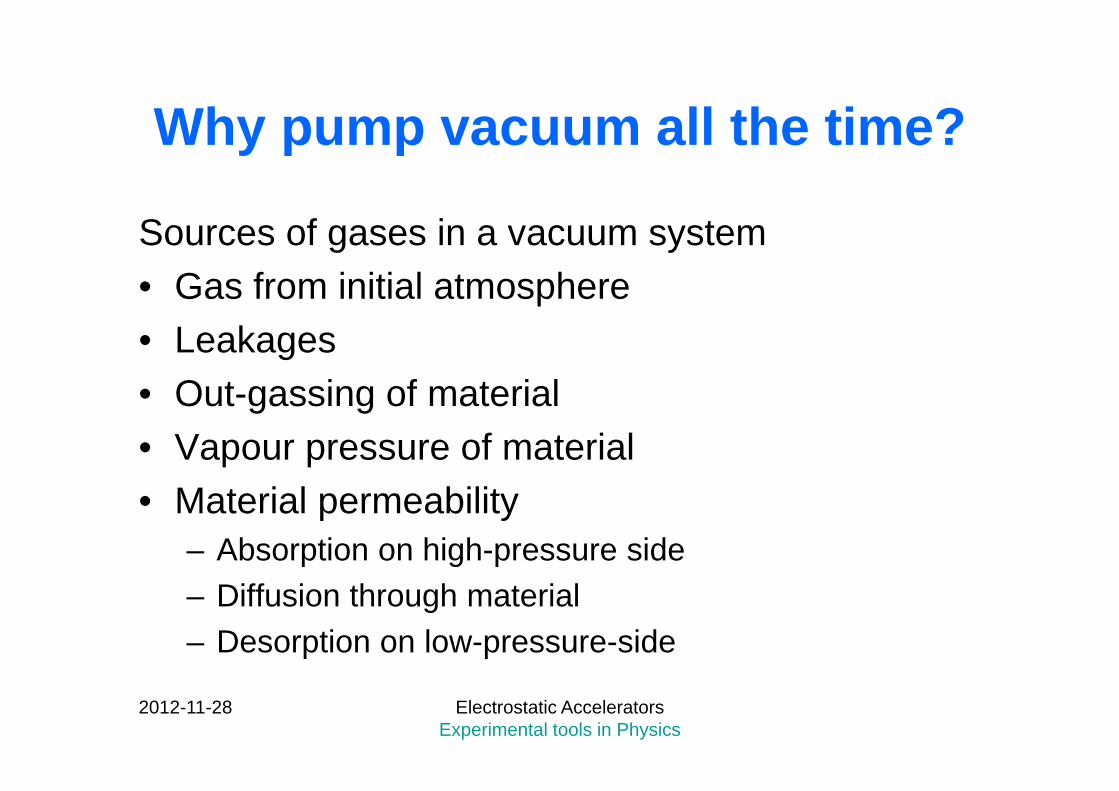
Why pump vacuum all the time?
Sources of gases in a vacuum system• Gas from initial atmosphere• Leakages• Out-gassing of material• Vapour pressure of material• Material permeability
– Absorption on high-pressure side– Diffusion through material– Desorption on low-pressure-side
2012-11-28 Electrostatic Accelerators Experimental tools in Physics
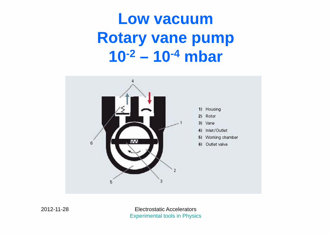
Low vacuumRotary vane pump
10-2 – 10-4 mbar
2012-11-28 Electrostatic Accelerators Experimental tools in Physics
High vacuum pumps
• Diffusion pump• (Cryopump)• Turbo-molecular pump
2012-11-28 Electrostatic Accelerators Experimental tools in Physics

Diffusion pump
2012-11-28 Electrostatic Accelerators Experimental tools in Physics
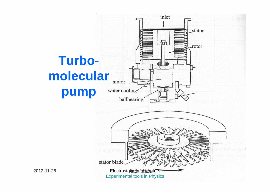
Turbo-molecular
pump
2012-11-28 Electrostatic Accelerators Experimental tools in Physics
Electrostatic accelerators and ion sources
2012-11-28 Electrostatic Accelerators Experimental tools in Physics
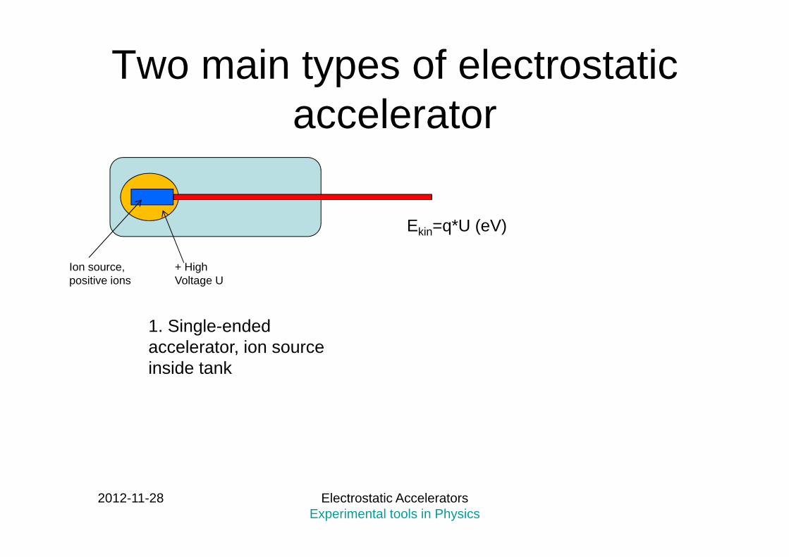
Two main types of electrostaticaccelerator
2012-11-28 Electrostatic Accelerators Experimental tools in Physics
+ High Voltage U
Ion source, positive ions
1. Single-endedaccelerator, ion sourceinside tank
Ekin=q*U (eV)
2012-11-28 Electrostatic Accelerators Experimental tools in Physics
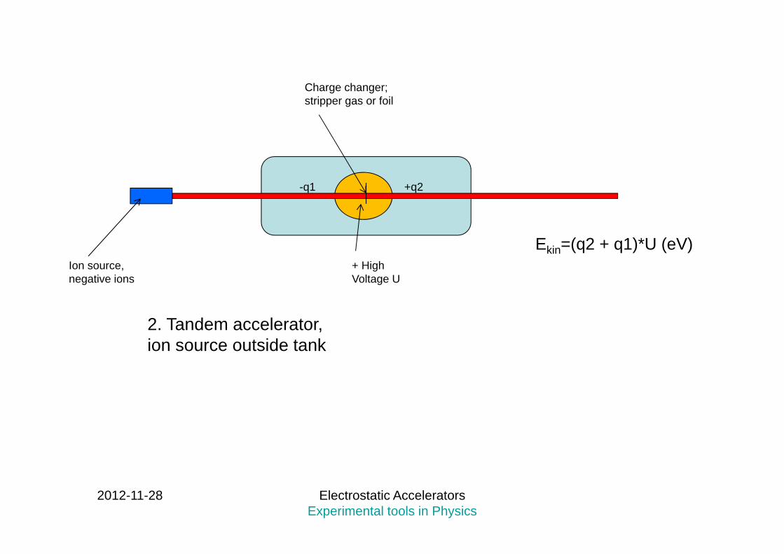
+ High Voltage U
Ion source, negative ions
2. Tandem accelerator, ion source outside tank
Charge changer; stripper gas or foil
-q1 +q2
Ekin=(q2 + q1)*U (eV)
2012-11-28 Electrostatic Accelerators Experimental tools in Physics
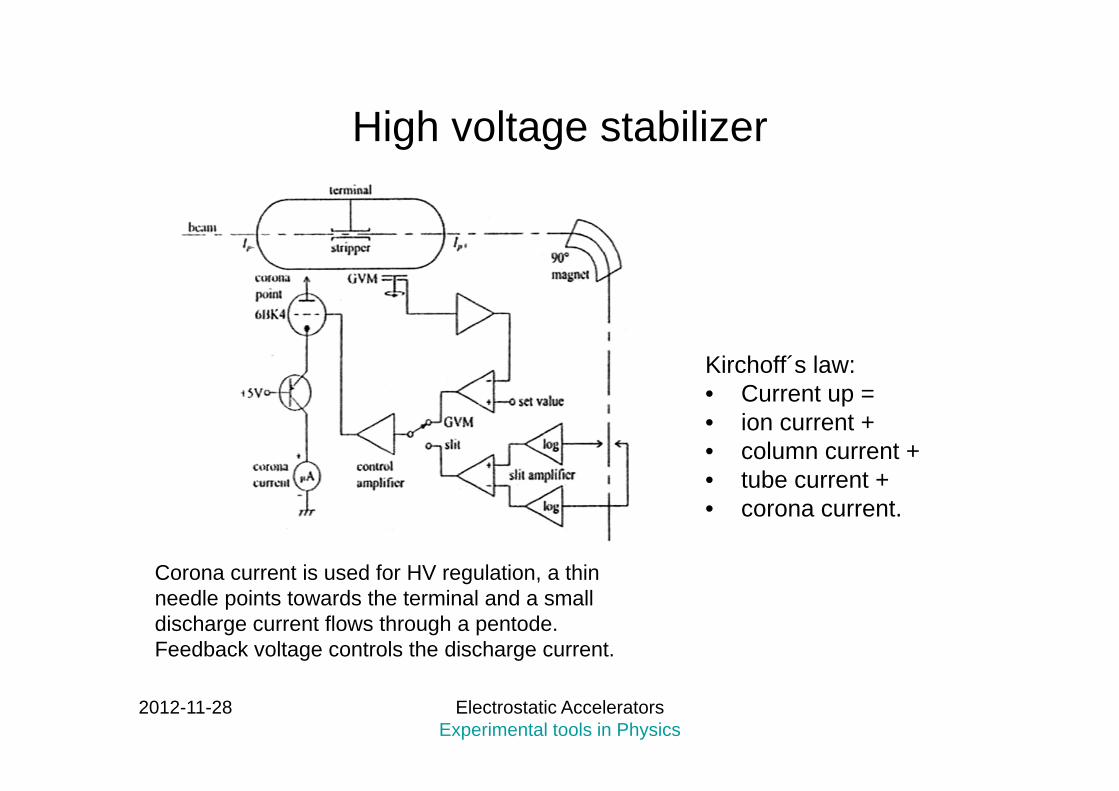
High voltage stabilizer
Kirchoff´s law: • Current up = • ion current + • column current + • tube current + • corona current.
Corona current is used for HV regulation, a thin needle points towards the terminal and a small discharge current flows through a pentode. Feedback voltage controls the discharge current.
2012-11-28 Electrostatic Accelerators Experimental tools in Physics
Ion sources• The purpose of the ion source is to produce
either positive or negative ions from neutral atoms.
• Positive ion sources are placed inside the tank of a single-ended accelerator;
• negative ion sources inject the ion beam into the tank of a tandem accelerator.
• Different types of sources may be used depending on the mass and charge of the desired ion.

2012-11-28 Electrostatic Accelerators Experimental tools in Physics
Ion sources – Duoplasmatronpositive (and negative)
2012-11-28 Electrostatic Accelerators Experimental tools in Physics
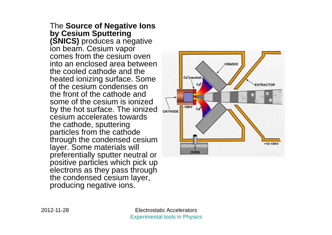
The Source of Negative Ions by Cesium Sputtering (SNICS) produces a negative ion beam. Cesium vapor comes from the cesium oven into an enclosed area between the cooled cathode and the heated ionizing surface. Some of the cesium condenses on the front of the cathode and some of the cesium is ionized by the hot surface. The ionized cesium accelerates towards the cathode, sputtering particles from the cathode through the condensed cesium layer. Some materials will preferentially sputter neutral or positive particles which pick up electrons as they pass through the condensed cesium layer, producing negative ions.
2012-11-28 Electrostatic Accelerators Experimental tools in Physics
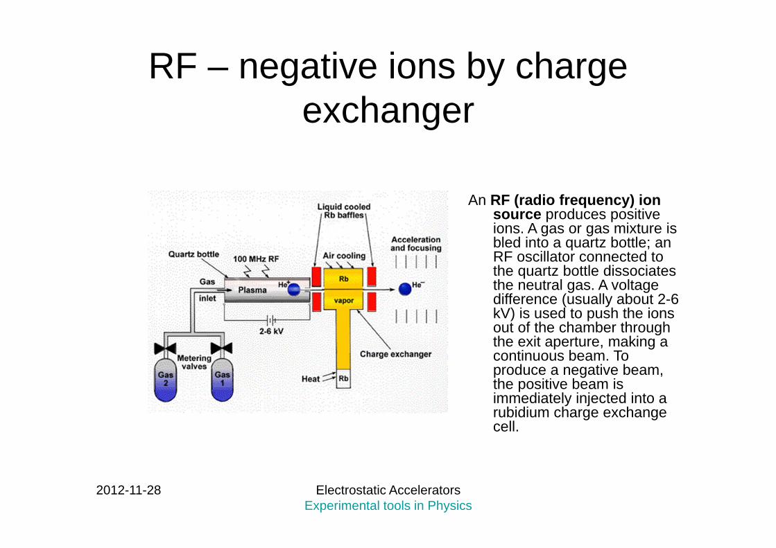
RF – negative ions by charge exchanger
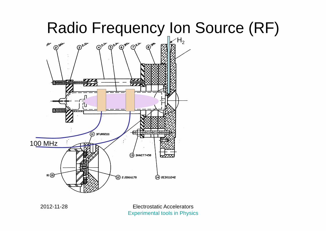
An RF (radio frequency) ion source produces positive ions. A gas or gas mixture is bled into a quartz bottle; an RF oscillator connected to the quartz bottle dissociates the neutral gas. A voltage difference (usually about 2-6 kV) is used to push the ions out of the chamber through the exit aperture, making a continuous beam. To produce a negative beam, the positive beam is immediately injected into a rubidium charge exchange cell.
2012-11-28 Electrostatic Accelerators Experimental tools in Physics
Radio Frequency Ion Source (RF)H2
100 MHz

2012-11-28 Electrostatic Accelerators Experimental tools in Physics
Radio Frequency Ion Source (RF)H2
100 MHz
20 µA p
+ 20 kV (extractor voltage)
Probe
1-2 kV
2012-11-28 Electrostatic Accelerators Experimental tools in Physics
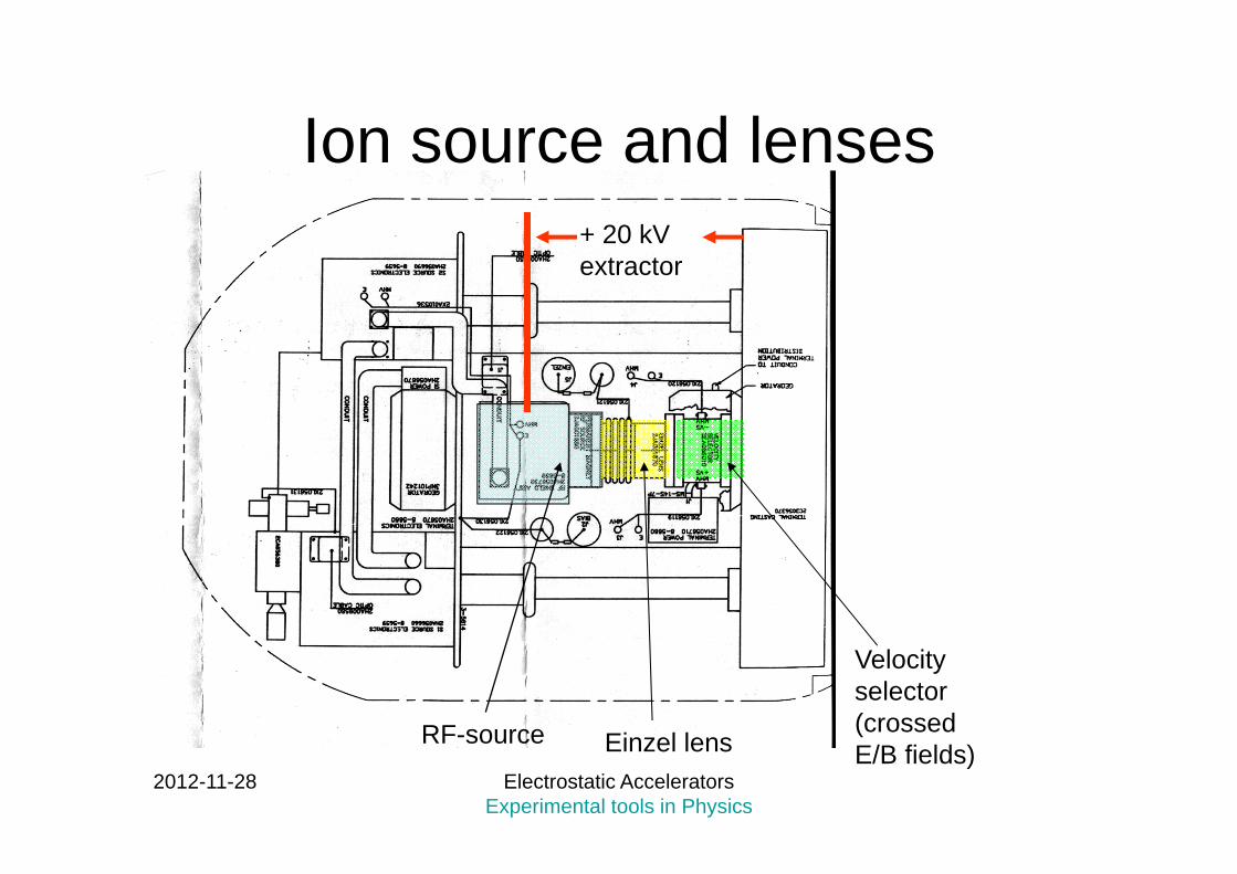
Ion source and lenses
RF-source Einzel lens
Velocity selector (crossed E/B fields)
+ 20 kV extractor
2012-11-28 Electrostatic Accelerators Experimental tools in Physics
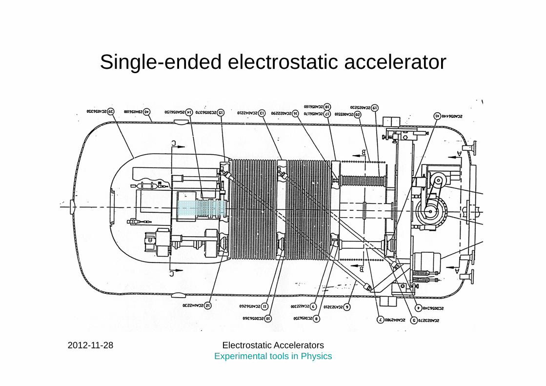
Single-ended electrostatic accelerator

2012-11-28 Electrostatic Accelerators Experimental tools in Physics
Microbeam acceleratorin Lund
2012-11-28 Electrostatic Accelerators Experimental tools in Physics
Charging system
• The purpose of the charging system is to generate the high voltage to be used for ion acceleration.
• Pelletron• Transformer/ rectifier system

2012-11-28 Electrostatic Accelerators Experimental tools in Physics
The Pelletron
Pelletron chains are made of metal pellets connected by insulating nylon links and are charged by an induction scheme that does not use rubbing contacts or corona discharges.
2012-11-28 Electrostatic Accelerators Experimental tools in Physics
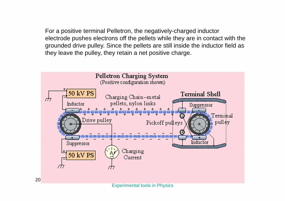
For a positive terminal Pelletron, the negatively-charged inductor electrode pushes electrons off the pellets while they are in contact with the grounded drive pulley. Since the pellets are still inside the inductor field as they leave the pulley, they retain a net positive charge.

2012-11-28 Electrostatic Accelerators Experimental tools in Physics
The chain then transports this charge to the high-voltage terminal, where the reverse process occurs. When it reaches the terminal, the chain passes through a negatively-biased suppressor electrode which prevents arcing as the pellets make contact with the terminal pulley. As the pellets leave the suppressor, charge flows smoothly onto the terminal pulley, giving the terminal a net positive charge. Most Pelletrons, as shown in the charging system diagram, employ "down-charging" as well as "up-charging."
2012-11-28 Electrostatic Accelerators Experimental tools in Physics
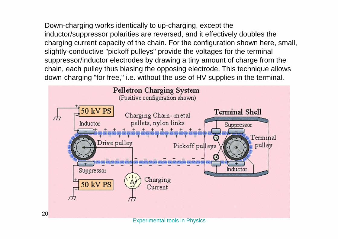
Down-charging works identically to up-charging, except the inductor/suppressor polarities are reversed, and it effectively doubles the charging current capacity of the chain. For the configuration shown here, small, slightly-conductive "pickoff pulleys" provide the voltages for the terminal suppressor/inductor electrodes by drawing a tiny amount of charge from the chain, each pulley thus biasing the opposing electrode. This technique allows down-charging "for free," i.e. without the use of HV supplies in the terminal.
2012-11-28 Electrostatic Accelerators Experimental tools in Physics
• Depending on the particular design options, the system delivers charging currents of 100 - 200 µA or more per chain to the high voltage terminal. The drive pulleys, typically 30 cm to 60 cm in diameter, and motors are supported on movable platforms which are
counterweighted, automatically providing proper chain tension.
2012-11-28 Electrostatic Accelerators Experimental tools in Physics
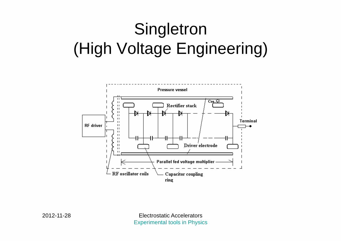
Singletron (High Voltage Engineering)

2012-11-28 Electrostatic Accelerators Experimental tools in Physics

2012-11-28 Electrostatic Accelerators Experimental tools in Physics
CENBG, Bordeaux
2012-11-28 Electrostatic Accelerators Experimental tools in Physics
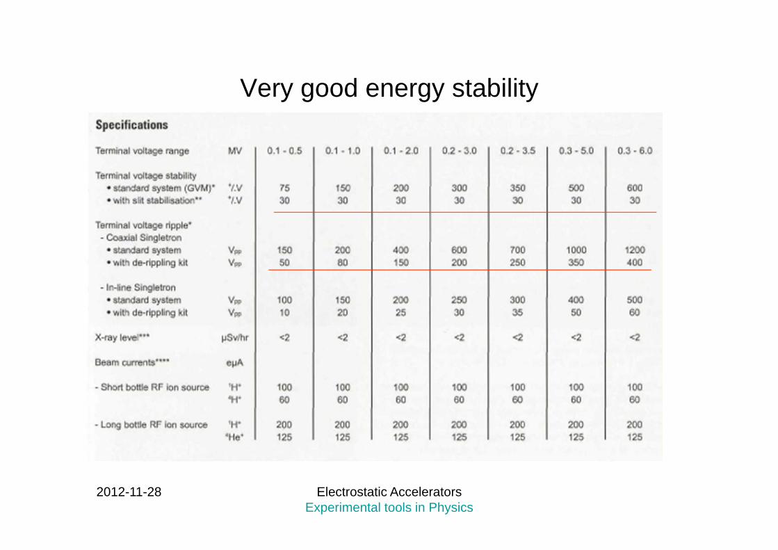
Very good energy stability
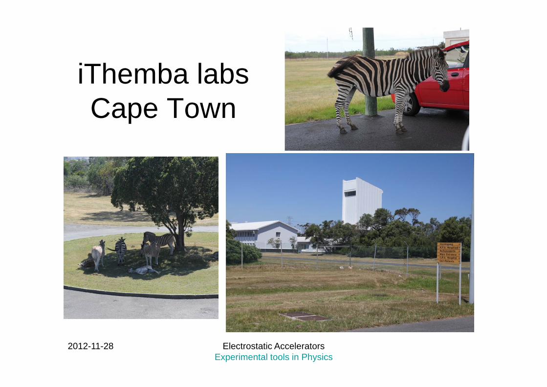
iThemba labsCape Town
2012-11-28 Electrostatic Accelerators Experimental tools in Physics

6 MV vertical VDG.
2012-11-28 Electrostatic Accelerators Experimental tools in Physics
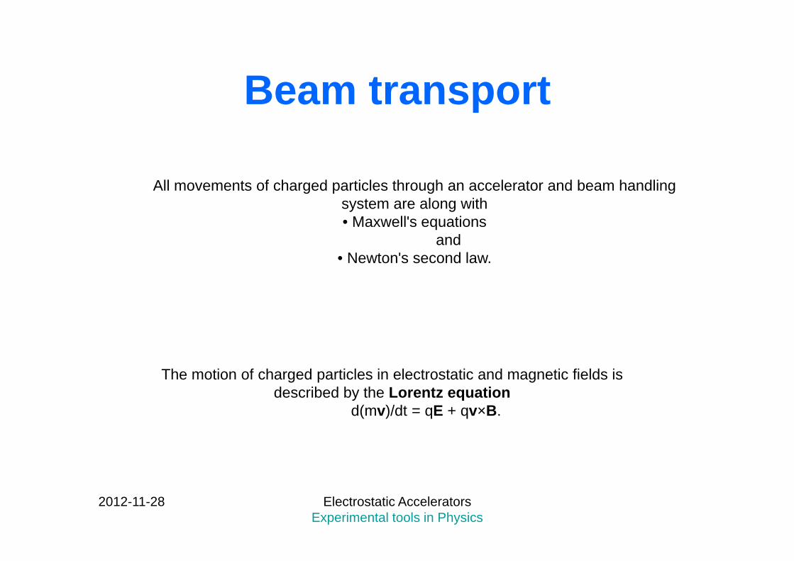
Beam transport
All movements of charged particles through an accelerator and beam handling system are along with • Maxwell's equations
and • Newton's second law.
The motion of charged particles in electrostatic and magnetic fields is described by the Lorentz equation
d(mv)/dt = qE + qv×B.
2012-11-28 Electrostatic Accelerators Experimental tools in Physics

Simple case: Electrostatic field
Consider two parallel plates having an electrostatic field E between them.
Positively charged particle in a uniform electrostatic field.
0F
qEdt
ydmF
0F
z
y2
2
y
x
2012-11-28 Electrostatic Accelerators Experimental tools in Physics
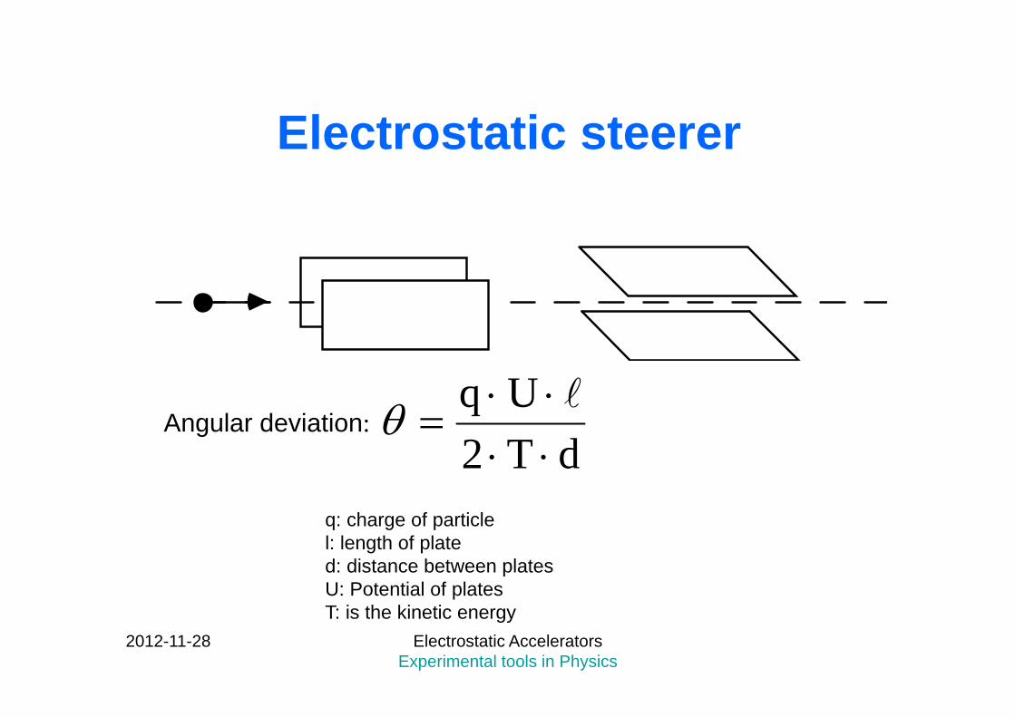
Electrostatic steerer
Angular deviation:dT2
Uq
q: charge of particlel: length of plated: distance between platesU: Potential of platesT: is the kinetic energy
2012-11-28 Electrostatic Accelerators Experimental tools in Physics

Aperture
+
-
E
B
Velocity filter (or cross-field analyser, or Wien filter)
For the undeflected particles the two forces must be identicalFE = FB
orqE = qvB
Velocity selector!
Electrostatic field E applied at right angle to the beam and a magnetic field B orthogonal to both E and the beam.
FB
FE
2012-11-28 Electrostatic Accelerators Experimental tools in Physics
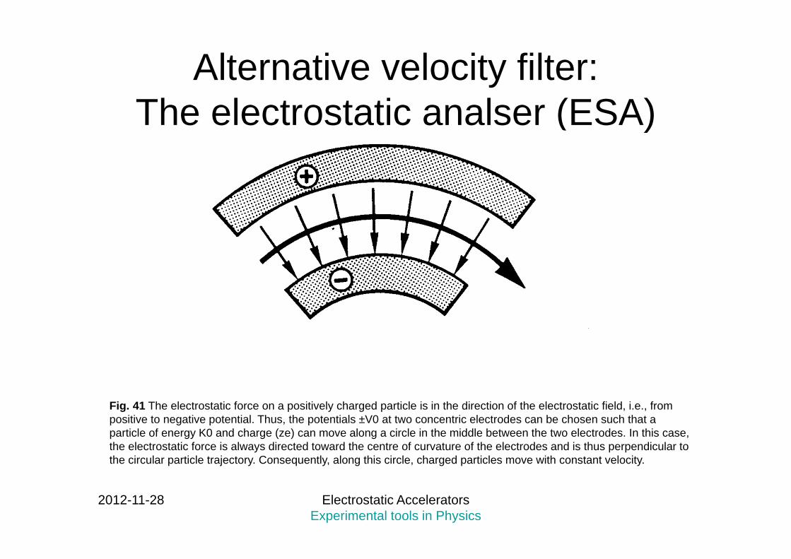
Alternative velocity filter: The electrostatic analser (ESA)
Fig. 41 The electrostatic force on a positively charged particle is in the direction of the electrostatic field, i.e., from positive to negative potential. Thus, the potentials ±V0 at two concentric electrodes can be chosen such that a particle of energy K0 and charge (ze) can move along a circle in the middle between the two electrodes. In this case, the electrostatic force is always directed toward the centre of curvature of the electrodes and is thus perpendicular to the circular particle trajectory. Consequently, along this circle, charged particles move with constant velocity.
2012-11-28 Electrostatic Accelerators Experimental tools in Physics
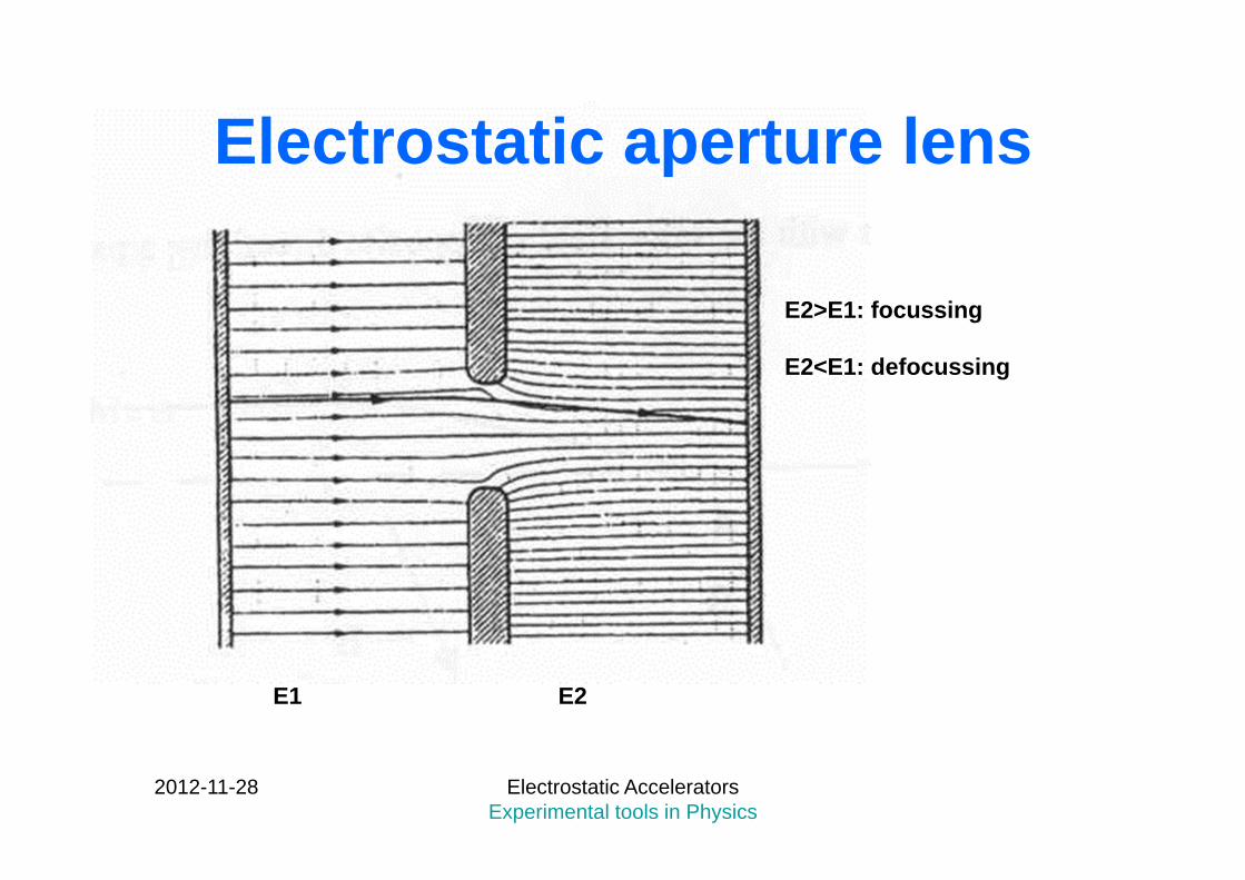
Electrostatic aperture lens
E1 E2
E2>E1: focussing
E2<E1: defocussing
2012-11-28 Electrostatic Accelerators Experimental tools in Physics
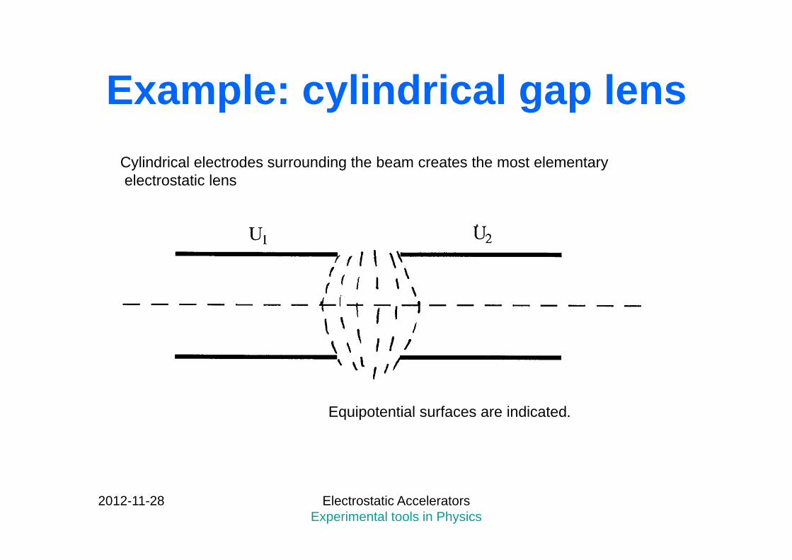
Example: cylindrical gap lensCylindrical electrodes surrounding the beam creates the most elementaryelectrostatic lens
Equipotential surfaces are indicated.
2012-11-28 Electrostatic Accelerators Experimental tools in Physics
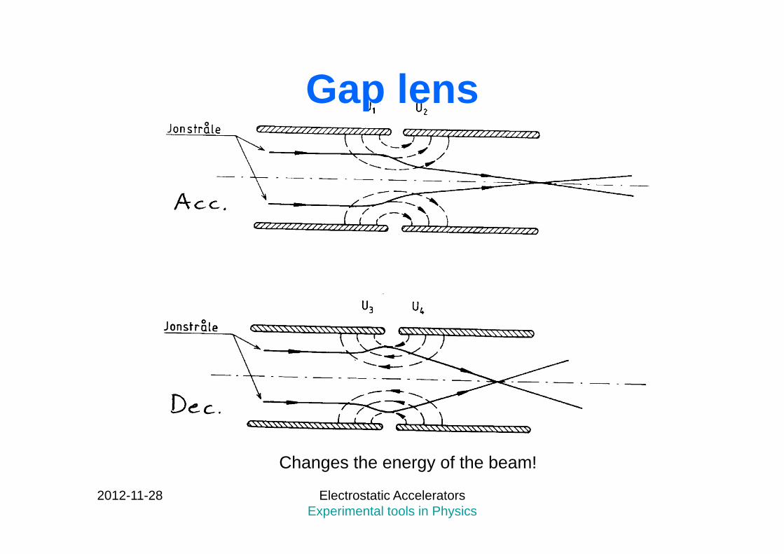
Gap lens
Changes the energy of the beam!
2012-11-28 Electrostatic Accelerators Experimental tools in Physics

Einzel lens: no energy change!
2012-11-28 Electrostatic Accelerators Experimental tools in Physics

Electrostatic quadrupole lens
2012-11-28 Electrostatic Accelerators Experimental tools in Physics

Magnetic fields
z
y
x
B
R=mv/qB
2012-11-28 Electrostatic Accelerators Experimental tools in Physics
Dipole magnet,changes the beamdirection
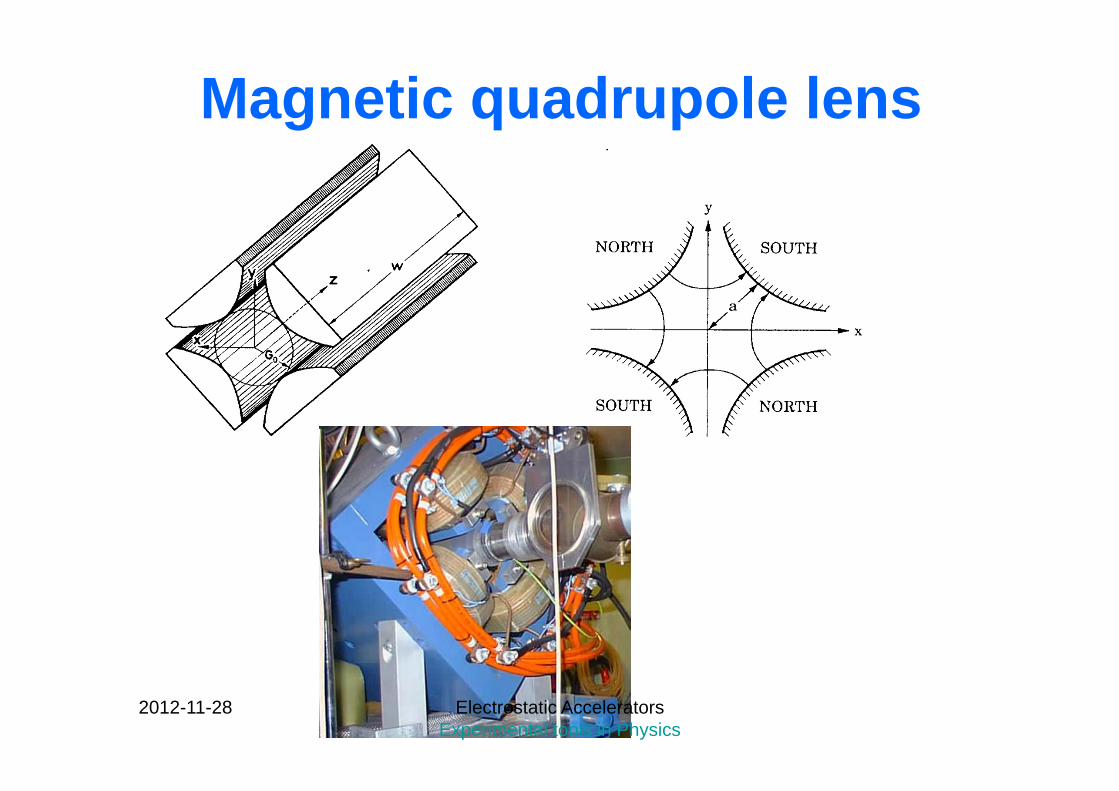
Magnetic quadrupole lens
2012-11-28 Electrostatic Accelerators Experimental tools in Physics

Q-pole field
2012-11-28 Electrostatic Accelerators Experimental tools in Physics
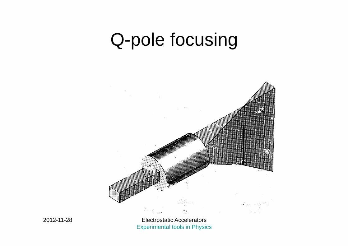
Q-pole focusing
2012-11-28 Electrostatic Accelerators Experimental tools in Physics
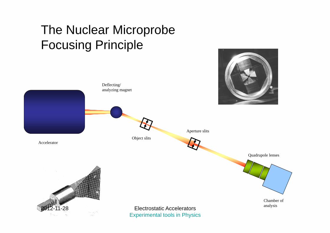
The Nuclear MicroprobeFocusing Principle
Quadrupole lenses
Chamber of analysis
Aperture slits
Object slits
Deflecting/ analyzing magnet
Accelerator
2012-11-28 Electrostatic Accelerators Experimental tools in Physics

Ion optics tools
2012-11-28 Electrostatic Accelerators Experimental tools in Physics
x
y
z
Ion Coordinates: x, y, zAngles: dx/dz, dy/dz
x (mm)
x’=dx/dz (mrad)
Phase space
y (mm)
y’ (mrad)
Transfer matricesfor rays of the beam

LTH-NANOBEAM-E
Horizontal /Vertical focus orderVH, HV, VH (-++--+)
H
V
2012-11-28 Electrostatic Accelerators Experimental tools in Physics
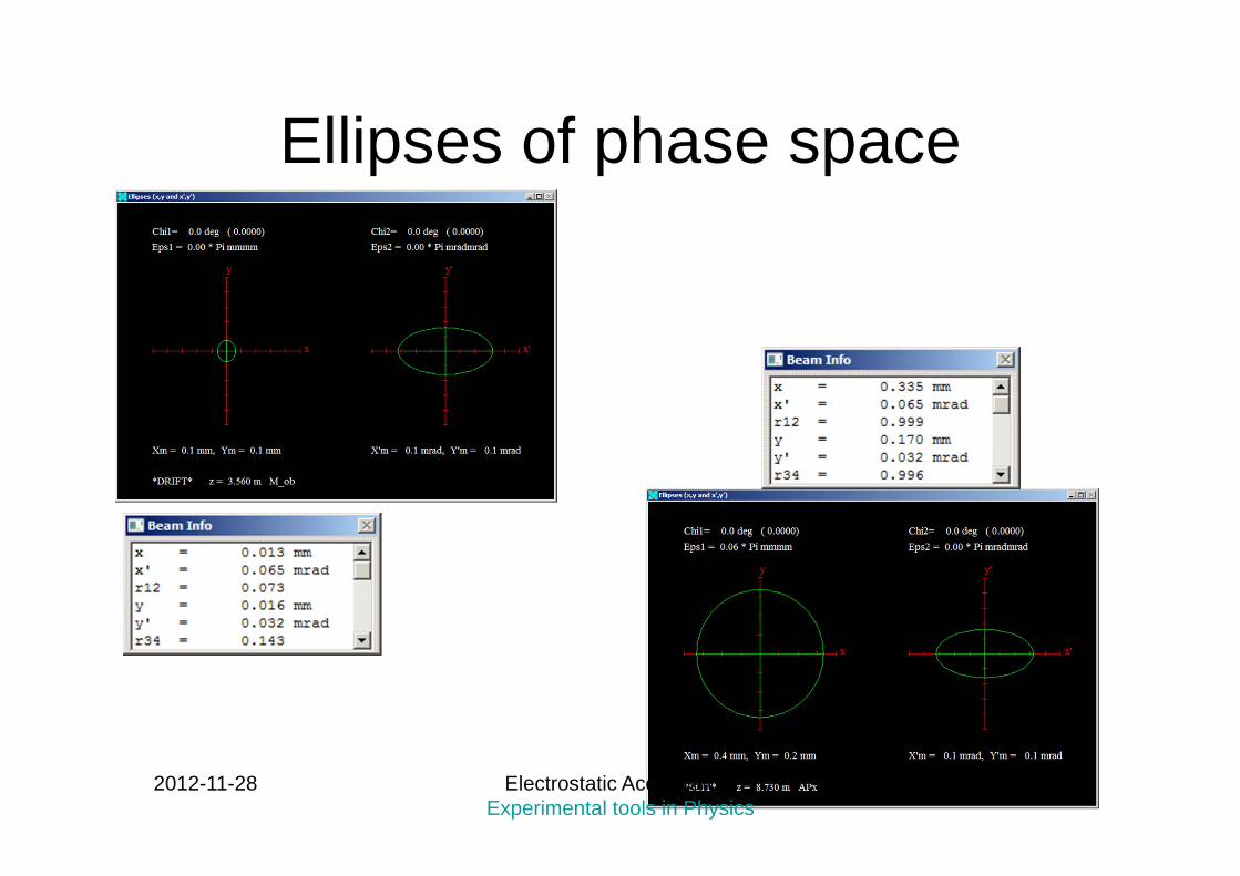
Ellipses of phase space
2012-11-28 Electrostatic Accelerators Experimental tools in Physics
2012-11-28 Electrostatic Accelerators Experimental tools in Physics

2012-11-28 Electrostatic Accelerators Experimental tools in Physics
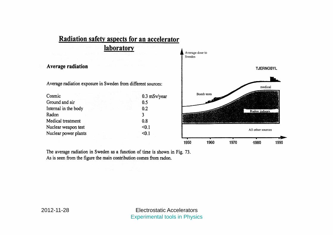
Accelerator: X-rays and -rays are expected from the acceleration tubewhere electrons may be released and accelerated against the high voltageterminal.
Modern machines have permanent magnets along the tube to force electronsinto spiral orbits instead. Bad vacuum can quickly increase radiation due to collisions with molecules.For electrostatic accelerators running at energies below 3MeV, it will normallynot be a problem to stay close to the accelerator.For cyclotrons (and larger) – on the other hand, radiation is intense and the accelerator must be heavily shielded with thick concrete walls.
Target: , n may be produced and depends of the type of target, mass, energyand intensity of the beams. Deuterons produce easily neutrons when collidingwith matter.
Activation of beam line components: -rays. Declines with time after beam-off.
The potential radiation hazard at an accelerator laboratory has threemain sources.
2012-11-28 Electrostatic Accelerators Experimental tools in Physics
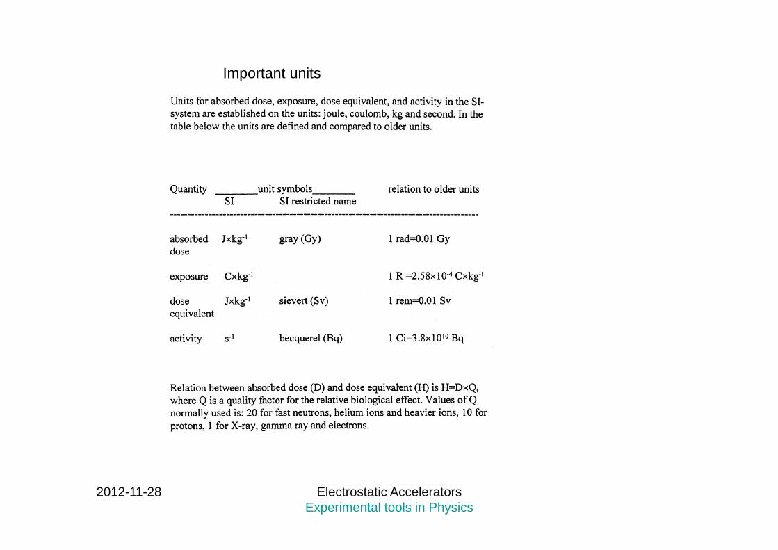
Important units

2012-11-28 Electrostatic Accelerators Experimental tools in Physics
Radiation and the DNA

2012-11-28 Electrostatic Accelerators Experimental tools in Physics
MONITORS

2012-11-28 Electrostatic Accelerators Experimental tools in Physics
END
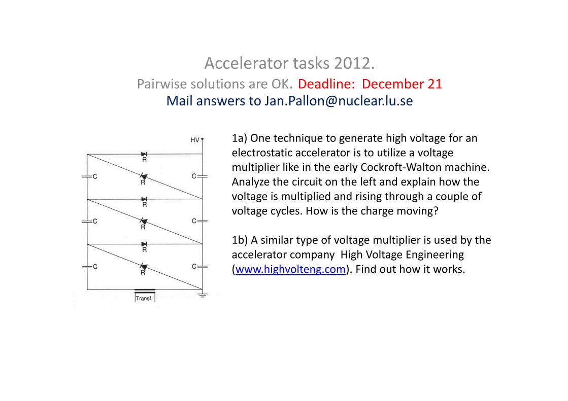
Accelerator tasks 2012. Pairwise solutions are OK. Deadline: December 21
Mail answers to [email protected]
1a) One technique to generate high voltage for an electrostatic accelerator is to utilize a voltagemultiplier like in the early Cockroft‐Walton machine. Analyze the circuit on the left and explain how the voltage is multiplied and rising through a couple of voltage cycles. How is the charge moving?
1b) A similar type of voltage multiplier is used by the accelerator company High Voltage Engineering(www.highvolteng.com). Find out how it works.

Cyclotron energy
2a. Derive an expression for the kinetic energy of ions accelerated in a cyclotrongiven mass, charge, radius and magnetic field.
2b. When (at what energy) will relativistic mass changes start to limit the use of the cyclotron? Specify what percentage of mass change you assume (e.g, 1, 5 or 10%)
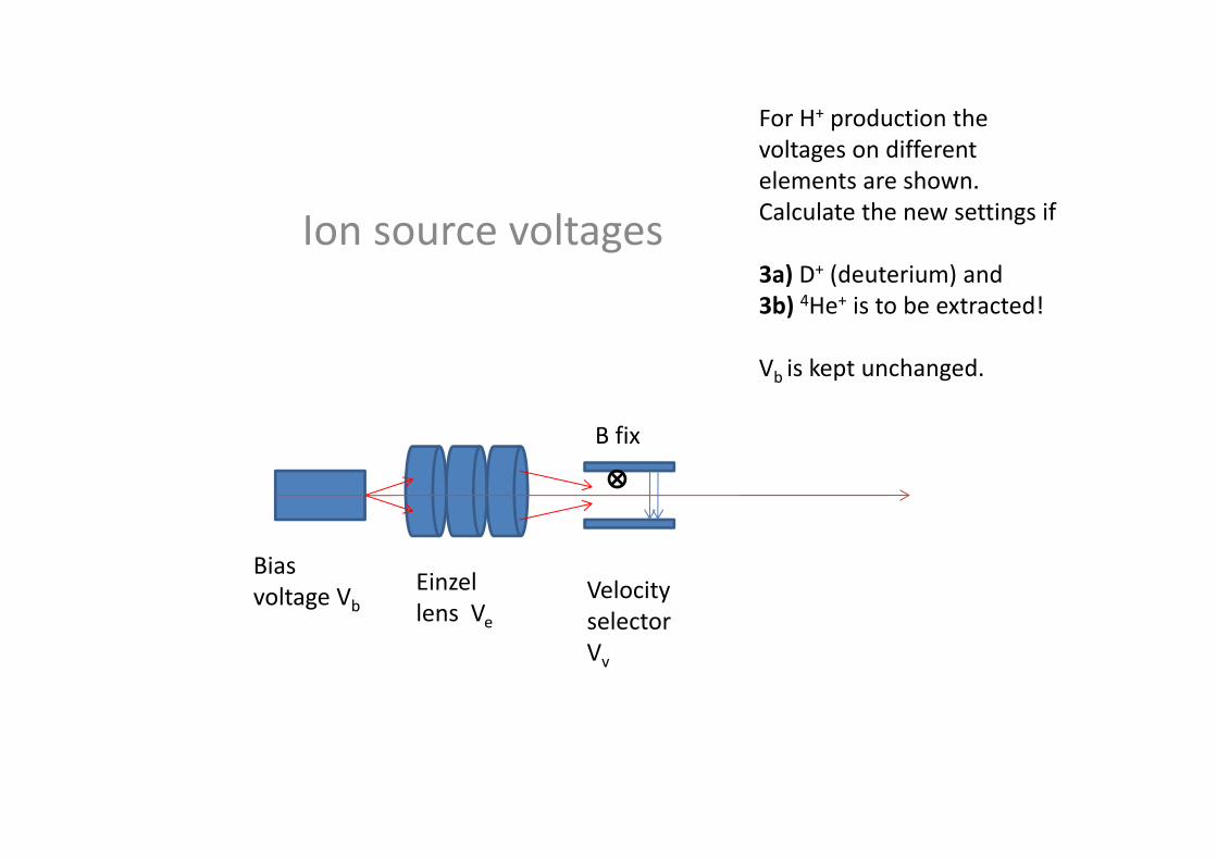
Ion source voltages
Biasvoltage Vb
Einzellens Ve
VelocityselectorVv
B fix
For H+ production the voltages on different elements are shown. Calculate the new settings if
3a) D+ (deuterium) and 3b) 4He+ is to be extracted!
Vb is kept unchanged.
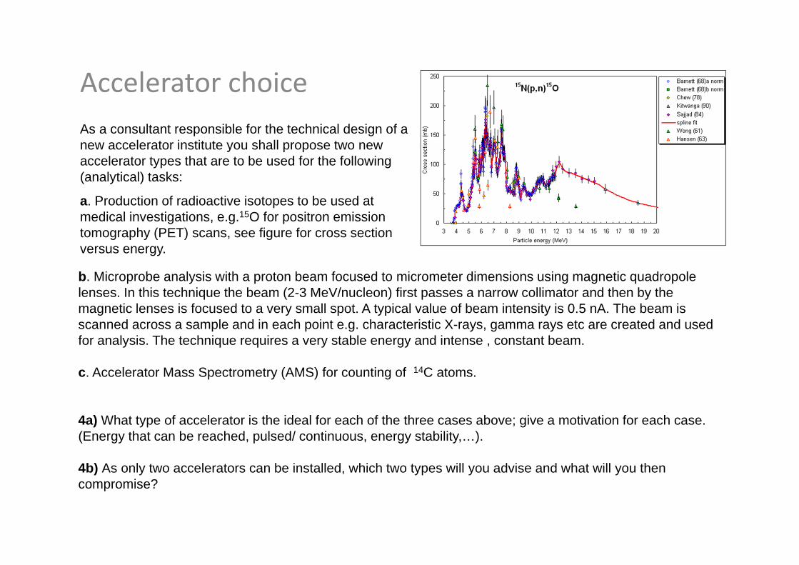
Accelerator choiceAs a consultant responsible for the technical design of a new accelerator institute you shall propose two new accelerator types that are to be used for the following (analytical) tasks:
a. Production of radioactive isotopes to be used at medical investigations, e.g.15O for positron emission tomography (PET) scans, see figure for cross section versus energy.
b. Microprobe analysis with a proton beam focused to micrometer dimensions using magnetic quadropolelenses. In this technique the beam (2-3 MeV/nucleon) first passes a narrow collimator and then by the magnetic lenses is focused to a very small spot. A typical value of beam intensity is 0.5 nA. The beam is scanned across a sample and in each point e.g. characteristic X-rays, gamma rays etc are created and used for analysis. The technique requires a very stable energy and intense , constant beam.
c. Accelerator Mass Spectrometry (AMS) for counting of 14C atoms.
4a) What type of accelerator is the ideal for each of the three cases above; give a motivation for each case. (Energy that can be reached, pulsed/ continuous, energy stability,…).
4b) As only two accelerators can be installed, which two types will you advise and what will you then compromise?