experimentalexperimental installation …€¦ · · 2015-05-15experimentalexperimental...
TRANSCRIPT

Electroair Acquisition Corp. IM Experimental Page 1 of 31 Revision 03 Prepared By: EAC 05/13/2015
ElectroairElectroairElectroairElectroair 317 Catrell Dr, Suite #2317 Catrell Dr, Suite #2317 Catrell Dr, Suite #2317 Catrell Dr, Suite #2
Howell, MI 48843 U.S.A.Howell, MI 48843 U.S.A.Howell, MI 48843 U.S.A.Howell, MI 48843 U.S.A. Ph: 517Ph: 517Ph: 517Ph: 517----552552552552----9390 Fax: 5179390 Fax: 5179390 Fax: 5179390 Fax: 517----552552552552----9391939193919391
Email: [email protected]: [email protected]: [email protected]: [email protected]
ExperimentalExperimentalExperimentalExperimental Installation ManualInstallation ManualInstallation ManualInstallation Manual
EISEISEISEIS----1 & EIS1 & EIS1 & EIS1 & EIS----2222
"PROPRIETARY/CONFIDENTIAL" The information contained in or disclosed by this document is considered proprietary to Electroair Acquisition Corp. This document and the information contained or disclosed herein shall not be used, copied or reproduced in whole or in part, nor shall the contents be revealed in any manner to any person unless written permission is obtained from Electroair Acquisition Corp.

Electroair Acquisition Corp. IM Experimental Page 2 of 31 Revision 03 Prepared By: EAC 05/13/2015
Table of Contents: Ignition System Technical Discussion ............................................................................. 3
Ignition System Basics ................................................................................................. 3
Dual Magneto System Review ..................................................................................... 3
EIS Overview & Primer ................................................................................................. 3
How the Electroair EIS Works ...................................................................................... 4
High Resolution Crankshaft Position Sensor ................................................................ 5
Spark Plug Discussion .................................................................................................... 6
EIS-1 & EIS-2 Kit Description & Requirements ............................................................... 7
EIS-1 & EIS-2 Kit Contents: ............................................................................................ 7
EIS-1 Kit Contents: ....................................................................................................... 7
EIS-2 Kit Contents: ....................................................................................................... 7
Receiving and Acceptance Checking of EIS Kit .............................................................. 8
Overview of EIS Installation ............................................................................................ 9
Installation of EIS .......................................................................................................... 10
Glossary and Abbreviations: ......................................................................................... 31
Log of Revisions: ........................................................................................................... 31
Table of Figures: Figure 1: Vacuum Advance Curve.................................................................................. 4
Figure 2: Installation of MTH Alignment Pin ................................................................. 11
Figure 3: Picture of Example Scenario from Step 4b.................................................... 12
Figure 4: Picture of step 4c .......................................................................................... 13
Figure 5: Picture of Step 4d .......................................................................................... 13
Figure 6: Picture of Typical installation of CSTW on a Continental 470 engine. ........... 15
Figure 7: Picture of components that make up the Continental CSTW Sensor Bracket15
Figure 8: Picture of Typical installation of CSTW on a Lycoming 540 engine. ............. 16
Figure 9: Picture of components that make up the Lycoming CSTW Sensor Bracket .. 16
Figure 10: Crank Shaft Trigger Wheel Positioning ....................................................... 17
Figure 11: CSTW Installation – Exploded View; NOT TO SCALE ................................ 18
Figure 12: EIS Controller Dimensions .......................................................................... 19
Figure 13: Coil Pack Dimensions ................................................................................. 20
Figure 14: Spark Plug Wire Hardware Assembly ......................................................... 23
Figure 15: Coil Pack Tower IDs .................................................................................... 24
Figure 16: 4-Cylinder Electrical Overview .................................................................... 28
Figure 17: 6-Cylinder Electrical Overview .................................................................... 29

Electroair Acquisition Corp. IM Experimental Page 3 of 31 Revision 03 Prepared By: EAC 05/13/2015
Ignition System Technical Discussion
Ignition System Basics The goal of any ignition system in a four-stroke engine is to start the combustion event so that peak pressure, as a result of combustion, occurs between 10 & 17 degrees after top dead center (ATDC) of the piston travel. This is the generally accepted range and the starting point when talking about ignition systems. From here we work backwards to understand how ignition systems work and what improvements can be made in order to get the most out of the engine.
Dual Magneto System Review Traditional aircraft engines use a dual, or two, Magneto Ignition System (MIS). Both magnetos are timed to fire at a preset degree before Top Dead Center (TDC). The two magneto system can be made up of a number of combinations: one impulse coupled magneto and one direct drive magneto; two impulse coupled magnetos; or two magnetos that have some kind of “starting help” device like a shower of sparks or “Slick-Start” system. No matter the combination, the magnetos are responsible for supplying energy to the spark plugs causing a “spark” which is used to ignite a fuel/air mixture inside of the cylinder. For decades, this kind of ignition system has been used quite successfully in aircraft engines. Traditional aircraft ignition systems, however, have remained stagnant in technological development and because of their inherent limitations, hand-cuffed the engine’s ability to deliver peak performance. Magnetos have two big limitations: one, they produce a relatively small amount of energy; and two, they can only provide that energy (or spark) at a fixed time point in the crank-shaft rotation. Magnetos typically can provide 12,000V through about 5 degrees of crank rotation at the spark plug – less during the start sequence (6,000-8,000 volts during starting). The fixed time point where the spark occurs means that the magneto cannot adjust the spark event to compensate for variances in fuel/air mixtures. As fuel/air mixtures varies (either because of altitude, air density, fuel density, etc.), the time required to develop peak pressure from combustion also changes. If the ignition event timing doesn’t change, then the time where peak pressure occurs MUST change. When this happens, the experience is typically a loss of power.
EIS Overview & Primer There are two principle differences between a magneto (MIS) and an electronic ignition system (EIS): one, an EIS is able to deliver much higher energy to the spark plug for a long period of time (70,000V through about 20 degrees of crank rotation) at any RPM; and two, an EIS is able to vary the ignition timing based on changes in the fuel/air mixture. The very large voltage supplied to the spark plugs comes from using larger coils. The EIS’s ability to deliver that voltage at any RPM is because the output from the EIS is
Electroair Acquisition Corp. IM Experimental Page 4 of 31 Revision 03 Prepared By: EAC 05/13/2015
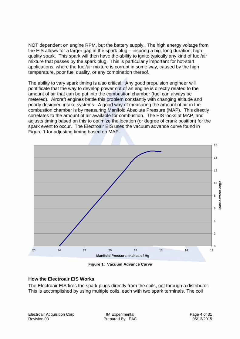
NOT dependent on engine RPM, but the battery supply. The high energy voltage from the EIS allows for a larger gap in the spark plug – insuring a big, long duration, high quality spark. This spark will then have the ability to ignite typically any kind of fuel/air mixture that passes by the spark plug. This is particularly important for hot-start applications, where the fuel/air mixture is corrupt in some way, caused by the high temperature, poor fuel quality, or any combination thereof. The ability to vary spark timing is also critical. Any good propulsion engineer will pontificate that the way to develop power out of an engine is directly related to the amount of air that can be put into the combustion chamber (fuel can always be metered). Aircraft engines battle this problem constantly with changing altitude and poorly designed intake systems. A good way of measuring the amount of air in the combustion chamber is by measuring Manifold Absolute Pressure (MAP). This directly correlates to the amount of air available for combustion. The EIS looks at MAP, and adjusts timing based on this to optimize the location (or degree of crank position) for the spark event to occur. The Electroair EIS uses the vacuum advance curve found in Figure 1 for adjusting timing based on MAP.
0
2
4
6
8
10
12
14
16
1214161820222426
Manifold Pressure, inches of Hg
Spa
rk A
dvan
ce A
ngle
Figure 1: Vacuum Advance Curve
How the Electroair EIS Works The Electroair EIS fires the spark plugs directly from the coils, not through a distributor. This is accomplished by using multiple coils, each with two spark terminals. The coil

Electroair Acquisition Corp. IM Experimental Page 5 of 31 Revision 03 Prepared By: EAC 05/13/2015
terminals are connected to the spark plugs, allowing one cylinder to fire on compression while its companion cylinder fires simultaneously on exhaust. Open spark gaps in the rotor and cap are eliminated, making wear and moisture problems a thing of the past. What sets the Electroair Electronic Ignition System apart from others is the ability to charge multiple ignition coils at the same time. This increased dwell time means that full spark energy is available over the entire RPM range (up to 9600 RPM at 12 volts). Unlike capacitive discharge systems that only put out one very short spark, the EIS puts out a full energy, long burning spark at the highest and most critical engine speeds. Long burn times assure effective burning of even rich fuel mixtures. The EIS Controller includes dual digital microprocessors using patented spark algorithms, which takes the electrical signal from the crankshaft (or mag timing housing) sensor, identifies top-dead center, and then keeps track of the remaining rotation. The EIS determines engine speed and computes the spark advance using the settings pre-set at the factory for the engine as a base-line. Settings from the factory are preset for the engine’s certified placarded timing. Additionally, the EIS receives engine manifold pressure information and advances the ignition to compensate for altitude and throttle position. Beyond the synchronization and firing the plugs at the correct advance angle, the EIS also computes the exact dwell time to produce 9 amps of coil current. Coil charging is dynamically measured, so changes in RPM, battery voltage, or temperature are accounted for on every spark. This corrects any errors that are caused by battery voltage or coil temperature changes and insures maximum spark energy.
High Resolution Crankshaft Position Sensor The EIS uses a single, high resolution, 60-minus-2 tooth crankshaft position trigger wheel. The trigger wheel is either installed in a timing mechanism that is installed in a mag hole (aka Mag Timing Housing or MTH), or a trigger wheel is installed directly on the crankshaft just behind the prop flange. This affords resolution unheard of in any other electronic ignition available today, offering spark accuracy of ¼ degree of crankshaft rotation. This accuracy means the system is ideal for the most demanding engine applications – that’s why the Electroair EIS has accomplished altitude and speed records in the industry. In summary, the Electroair EIS delivers more power because:
• Spark timing is precisely controlled under all conditions, including rapid engine acceleration.
• Longer dwell time and better propagation allows the engine to run better on various mixture settings.
• Accurate spark timing allows sustained engine operation closer to desired peak power timing.
• 100% spark energy up to 9600 RPM on 6 cylinder applications (at 12 volts). • Longer spark duration! • Built-in timing program.

Electroair Acquisition Corp. IM Experimental Page 6 of 31 Revision 03 Prepared By: EAC 05/13/2015
• No power draining magnetos to drive. • No moving parts to wear out or adjust.
Spark Plug Discussion The installation manual specifies the recommended gap for the engine application. This gap will be larger than a typical aircraft plug gap because of the higher energy output from the EIS. This is perfectly acceptable with the EIS ignition charging method, since the high load of the cylinder pressure will allow the voltage to be quite high at the electrode; the gap will keep the plug from seeing an over-voltage situation. The EIS system uses an inductive long duration charging method for the coils. Electroair’s experience has drawn us to the following guidelines for spark plug selection:
• Select aircraft spark plugs that will work with the EIS. For Lycoming engines, Electroair has found that the REM37BY (or equivalent) plugs work the best because they are easier to gap to the range required and fit the broadest heat range recommended by the engine manufacturers. (Fine wire plugs are also an excellent choice for Lycoming engines). For Continental Engines requiring long reach spark plugs, off-the-shelf fine wire spark plugs will generally be the easiest to adjust the gap. Electroair strongly recommends verifying the heat range for the engine and using the appropriate plugs.
• Electroair manufactures aviation spark plugs that are gapped at the factory to Electroair’s recommended wide gap of 0.036 inches. Electroair manufactures both massive electrode and fine wire spark plugs for various applications. The spark plug information can be found on the Electroair website (www.electroair.net). Electroair spark plugs have been FAA approved for use with Electroair’s certified EIS-61000 ignition systems. These plugs are only approved for use with Electroair’s EIS. Electroair spark plugs should not be used with magnetos.

Electroair Acquisition Corp. IM Experimental Page 7 of 31 Revision 03 Prepared By: EAC 05/13/2015
EIS-1 & EIS-2 Kit Description & Requirements EIS-1 & EIS-2 System Description & Requirements:
1. These EIS kits replace one magneto on the engine of a single engine aircraft 2. 12V or 24V electrical system 3. Manifold pressure line for installing the MAP sensor 4. Toggle Switch x1 (NOT PROVIDED IN EIS KIT) 5. 2 amp circuit breaker or fuse x1 (NOT PROVIDED IN EIS KIT) 6. 10 amp circuit breaker or fuse x1 (NOT PROVIDED IN EIS KIT)
Other items needed:
1. Basic tools and standard aircraft hardware required for mounting EIS controller, coil pack, and MAP sensor.
2. Electrical tools for cutting, stripping, and terminating various wiring. Also, it recommended having a good selection of cable ties for harness routing and tie-off.
EIS-1 & EIS-2 Kit Contents:
EIS-1 Kit Contents: 1. ___p/n 016-50000, EIS Controller 2. ___p/n 070-33400, 4-cylinder Coil Pack 3. ___p/n EA-001, Mag Timing Housing 4. ___p/n EA-002, MAP Sensor Box 5. ___p/n EA-004, Spark Plug Wires w/ termination hardware (2 bundles) 6. ___USB Drive Containing System Documents (Installation Manual)
EIS-2 Kit Contents: 1. ___p/n 016-50000, EIS Controller 2. ___p/n 070-33600, 6-cylinder Coil Pack 3. ___p/n EA-002, MAP Sensor Box 4. ___p/n EA-003, Crankshaft Timing Wheel w/ Pick-Up (Lycoming) 5. ___p/n EA-004, Spark Plug Wires w/ termination hardware (3 bundles) 6. ___USB Drive Containing System Documents (Installation Manual)
Electroair Acquisition Corp. IM Experimental Page 8 of 31 Revision 03 Prepared By: EAC 05/13/2015
Receiving and Acceptance Checking of EIS Kit
1. Review the packaging before acceptance from the freight carrier. If damaged, refuse the package.
2. Open the package. 3. Review the contents of the package to the content listing on the package. 4. Are all of the materials there?
a. Yes, proceed to step 5. b. No, contact the factory. Have the serial number of the kit available when
contacting. (factory 517-552-9390 or [email protected]) 5. Inspect the controller and MAP sensor for damage to the aluminum housing.
Verify that the placarded controller timing matched the placarded engine timing. If not contact Electroair 517-552-9390 or [email protected].
6. Inspect the wires for nicks and cracks. 7. Inspect the coil pack and plate for external damage. 8. Inspect the CSTW/MTH for external damage. 9. Are all materials acceptable?
a. Yes, proceed with installation. b. No, contact the factory. Have the serial number of the kit available when
contacting. (factory 517-552-9390 or [email protected])
If possible, store parts in original packaging when not in use. If not possible, wrap parts in cushioning material and place in one location. Review above prior to reinstallation. For latest copies of documentation, refer to www.electroair.net.
o AML o AFMS o ICA o Installation Manual o Trouble Shooting Instructions

Electroair Acquisition Corp. IM Experimental Page 9 of 31 Revision 03 Prepared By: EAC 05/13/2015
Overview of EIS Installation Thank you for purchasing an Electroair Ignition System for your aircraft. Electroair is confident that you will be happy with the performance of the EIS on your aircraft. The next several pages will take provide a step-by-step process of installing the EIS on the aircraft. Electroair hopes you will enjoy the experience and that this manual will provide clear direction and guidance through this process. This manual will cover the following general installation steps:
1. General Overview and recommendations 2. Removal of old ignition components 3. Set-up and installation of the Mag Timing Housing – four-cylinder engines 4. Set-up and installation of the Crank Shaft Timing Wheel – six-cylinder engines 5. Installation of the EIS Controller and Coil Pack 6. Installation of the MAP Sensor & vacuum line 7. Spark Plug Harness 8. Wiring 9. Final installation steps 10. Options
Electroair strongly recommends that reading through this entire installation procedure before installing the EIS on the aircraft. Make sure that any questions are answered before the actual installation. Also, make sure any extra components needed, e.g. cable ties, circuit breakers, switch terminations, etc., are available. Removal of old components and installation of new components is to be completed in compliance with CFR Title 14 Part 43, as applicable, and any Airframe or Engine Manufacturer Maintenance Procedures, as applicable. Above all else, use good common sense and professional judgment. An electronic ignition system is a high voltage device. If an EIS is improperly installed or misfired, severe damage could be caused to the EIS, aircraft, or installer including bodily injury or death. Please contact Electroair with any questions during this installation process. Good luck and happy flying!! Electroair

Electroair Acquisition Corp. IM Experimental Page 10 of 31 Revision 03 Prepared By: EAC 05/13/2015
Installation of EIS 1. General overview and recommendations
a. Read through the entire installation instructions before beginning the installation to make sure each step is understood. CALL ELECTROAIR (517-552-9390) if there are any questions or if any items that are unclear.
b. The installation of the EIS could take between 9-20 hours, depending on your skills for working on the engine & ignition systems. It is always advisable to seek help from a professional mechanic. Installation times can vary widely and are very aircraft and installer dependent!
c. This ignition system is designed to be installed by aviation professionals with the appropriate ratings and experience for maintaining General Aviation aircraft.
d. If pre-existing components on the airframe are in the way of or are in close proximity to the installation locations of the EIS components, Electroair Acquisition Corp. recommends that following the procedures listed below. NOTE: When making ANY changes or modifications to the aircraft or aircraft components, make sure all practices are in accordance with CFR Title 14 Part 43.
i. If the preexisting components can be relocated, move the components to an acceptable location on the airframe where they will not come into contact with the EIS component(s).
ii. If the preexisting components must come into contact or close proximity to the EIS component(s), make sure to protect all components from each other. This could mean, but not limited to, adding anti-chafing material, additional component securing devices, heat shielding material, etc.
e. Always use good safety and work practices. Use appropriate safety equipment (safety glasses, etc.) and precautions. The EIS is a high voltage system and if installed or tested incorrectly can cause substantial damage to both the system and YOU!
2. Removal of old ignition components
a. Remove cowling. Verify that Master Switch is off a nd battery is disconnected.
b. IMPORTANT: Determine which magneto will be replaced, either the right or the left.
c. Remove ignition harness from the spark plugs associated with the magneto that is being replaced.
d. Disconnect the P-lead that is installed on the magneto that is being replaced from the ignition switch.
e. Remove the selected magneto; retain the clips holding the magneto in place. If removing a pressurized magneto, ensure that the pre ssure line is properly plugged.
f. Remove the selected magneto’s ignition harness and selected magneto’s P-lead from ignition switch.
i. For 4-cylinder engines, retain mag holding clips if removing a Slick magneto. ii. For 6-cylinder engines, the accessory pad where the magneto was must be
covered; be sure to fasten the cover in place securely. CAUTION: On some engines like the Continental 470 series, the magneto drive gear is not attached to the magneto and MUST BE REMOVED from the accessory housing or it will damage the engine.

Electroair Acquisition Corp. IM Experimental Page 11 of 31 Revision 03 Prepared By: EAC 05/13/2015
g. Remove the magneto’s P-lead entirely from the aircraft system – a replacement P-lead wire is provided in the EIS wiring harness.
h. Remove spark plugs and replace with new plugs (recommended), or re-gap the existing plugs to the specified gap of 0.036 inches.
i. Remove the magneto drive gear/impulse coupling from the right hand magneto. Be careful not to damage the gear. Electroair recommends using a standard gear puller. (Note: 6-cylinder installations do not require the magneto gear). Retain gear for installation on Mag Timing Housing.
3. Set-up & Installation of Standard MTH; 4-cylinder ONLY
a. Retrieve p/n: EA-001 MTH and the EA-001 MTH Hardware Kit. b. Insert the woodruff key into the key slot on the MTH shaft. c. Place the direct dive magneto gear on the MTH shaft. Be sure to align the
Woodruff (half-moon shape) key with the slot in the gear. d. Install the washer and nut onto the MTH shaft and tighten the nut to the same
torque value as recommended by the magneto manufacturer (Bendix or Slick). Install the cotter pin through the castle nut and MTH shaft with the long end of the cotter pin facing away from the MTH. Bend the long end of the cotter pin over the end of the shaft and the short end along the side of the nut. The direct drive gear is now installed onto the MTH shaft.
e. Holding the MTH, insert the alignment pin in the alignment hole on the back cover (pin supplied with hardware kit). Slowly turn the gear on the front of the unit until the alignment pin drops into a second hole inside the MTH. The MTH is now set to Top Dead Center (TDC) and the MTH shaft should not be able to spin. Leave the alignment pin in the MTH and ready the engine for the MTH installation (next steps). See Figure 2 for an example.
Figure 2: Installation of MTH Alignment Pin
f. Clean magneto pad on the engine. Install new gasket on p/n: EA-001. g. VERIFY MASTER SWITCH IS OFF AND BATTERY IS DISCONNE CTED. h. Rotate the engine to Top Dead Center (TDC) for cylinder # 1. This done by
rotating the prop in the direction of the engine rotation until TDC is reached. Verify TDC using the timing marks found on the engine. Typically, the first set is on the fly wheel and the starter; they will line up at TDC; the second set may be another mark on the back-side of fly wheel which lines up with the engine case
Electroair Acquisition Corp. IM Experimental Page 12 of 31 Revision 03 Prepared By: EAC 05/13/2015
seam at TDC. If any of these indications are not correct, repeat this step until they are. Always rotate the engine in the direction that it rotates during operation.
i. Install the MTH into the proper magneto hole. Secure the MTH using the mag holding clips referenced in step 2e and secure per engine manufacturer specifications.
j. Remove the alignment pin. Failure to remove the MTH Alignment Pin may cause damage to the MTH, the engine, or both.
k. P/N EA-001 is now installed and timed properly.
4. Set-up & Installation of Impulse Coupled MTH; 4- cylinder ONLY Note: The Impulse Coupler in this installation is o nly being used as a spacer
for the drive gear. The Impulse Coupler does NOT re tard the timing of the EIS.
a. Retrieve p/n: EA-001IC Impulse Coupled MTH and the EA-001IC Impulse Coupled MTH Hardware Kit.
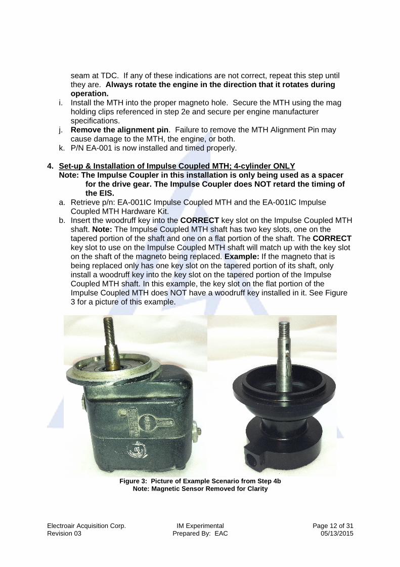
b. Insert the woodruff key into the CORRECT key slot on the Impulse Coupled MTH shaft. Note: The Impulse Coupled MTH shaft has two key slots, one on the tapered portion of the shaft and one on a flat portion of the shaft. The CORRECT key slot to use on the Impulse Coupled MTH shaft will match up with the key slot on the shaft of the magneto being replaced. Example: If the magneto that is being replaced only has one key slot on the tapered portion of its shaft, only install a woodruff key into the key slot on the tapered portion of the Impulse Coupled MTH shaft. In this example, the key slot on the flat portion of the Impulse Coupled MTH does NOT have a woodruff key installed in it. See Figure 3 for a picture of this example.
Figure 3: Picture of Example Scenario from Step 4b
Note: Magnetic Sensor Removed for Clarity
Electroair Acquisition Corp. IM Experimental Page 13 of 31 Revision 03 Prepared By: EAC 05/13/2015
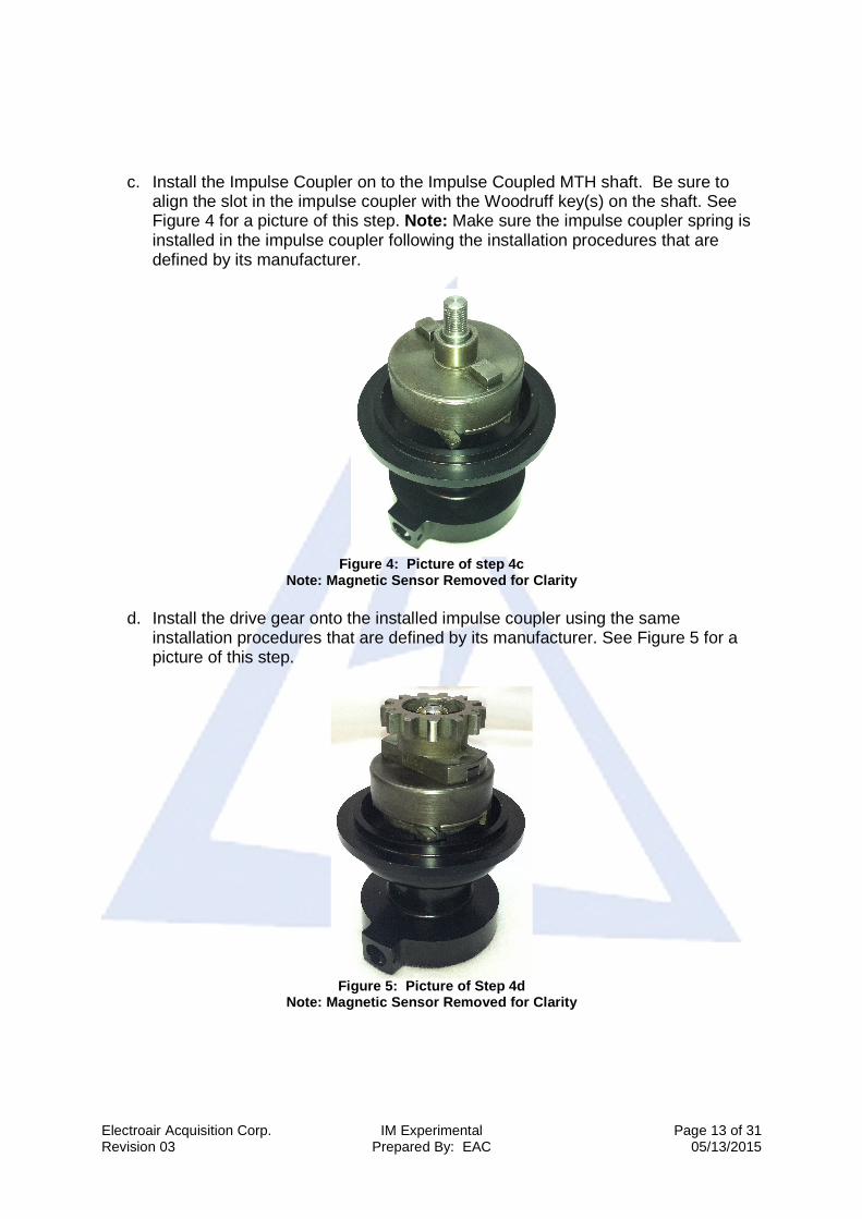
c. Install the Impulse Coupler on to the Impulse Coupled MTH shaft. Be sure to
align the slot in the impulse coupler with the Woodruff key(s) on the shaft. See Figure 4 for a picture of this step. Note: Make sure the impulse coupler spring is installed in the impulse coupler following the installation procedures that are defined by its manufacturer.
Figure 4: Picture of step 4c
Note: Magnetic Sensor Removed for Clarity
d. Install the drive gear onto the installed impulse coupler using the same installation procedures that are defined by its manufacturer. See Figure 5 for a picture of this step.
Figure 5: Picture of Step 4d
Note: Magnetic Sensor Removed for Clarity
Electroair Acquisition Corp. IM Experimental Page 14 of 31 Revision 03 Prepared By: EAC 05/13/2015
e. Install the washer and nut onto the Impulse Coupled MTH shaft and tighten the nut to 300-340 in-lbs. Install the cotter pin through the castle nut and impulse coupled MTH shaft with the long end of the cotter pin facing away from the MTH. Bend the long end of the cotter pin over the end of the shaft and the short end along the side of the nut. The impulse coupler and drive gear are now installed onto the impulse coupled MTH shaft.
f. Holding the Impulse Coupled MTH, insert the alignment pin in the alignment hole on the back cover (pin supplied with hardware kit). Slowly turn the gear on the front of the unit until the alignment pin drops into a second hole inside the Impulse Coupled MTH. The impulse coupled MTH is now set to Top Dead Center (TDC) and the Impulse Coupled MTH shaft should not be able to spin. Leave the alignment pin in the Impulse Coupled MTH and ready the engine for the Impulse Coupled MTH installation (next steps). See Figure 5 for an example.
g. Clean magneto pad on the engine. Install new gasket on p/n: EA-001IC. h. VERIFY MASTER SWITCH IS OFF AND BATTERY IS DISCONNE CTED. i. Rotate the engine to Top Dead Center (TDC) for cylinder # 1. This done by
rotating the prop in the direction of the engine rotation until TDC is reached. Verify TDC using the timing marks found on the engine. Typically, the first set is on the fly wheel and the starter; they will line up at TDC; the second set may be another mark on the back-side of fly wheel which lines up with the engine case seam at TDC. If any of these indications are not correct, repeat this step until they are. Always rotate the engine in the direction that it rotates during operation.
j. Install the Impulse Coupled MTH into the proper magneto hole. Secure the MTH using the MAG holding clips referenced in step 2e and secure per engine manufacturer specifications.
k. Remove the alignment pin. Failure to remove the MTH Alignment Pin may cause damage to the Impulse Coupled MTH, the engine, or both.
l. P/N EA-001IC is now installed and timed properly. 5. Set-up and installation of Crank-Shaft Timing Wheel (CSTW);
a. Retrieve p/n: EA-003 CSTW kit bag. b. Install the mag hole cover supplied in the EA-003 kit. c. Access is needed to the crankshaft between the engine case and the prop
flange. Remove those components necessary to accomplish this. d. Clean the crank area just in front of the crank shaft seal. CAUTION: The
exposed portion of the crank shaft is tin plated. Electroair Acquisition Corp. recommends using a liquid cleaner/degreaser. An abrasive (like sand paper or scotch-brite) will remove the plating.
e. Continental Installations (CSTW/Magnetic Pick-Up Br acket Installation)

Electroair Acquisition Corp. IM Experimental Page 15 of 31 Revision 03 Prepared By: EAC 05/13/2015
i. Temporarily fit the CSTW on the crank with the trigger wheel (timing teeth) toward the engine case. Slide the CSTW toward the prop flange. (Silver side of the CSTW to the engine case, black side to the propeller).
ii. Temporarily install the pick-up bracket: Remove the first two, forward, top case nuts and install the bracket/pick-up holder assembly (see Figure 3); verify that the center seam of the engine case aligns with the center of the large hole in the Sensor Holder, adjust spacing with flat washers under the bracket if necessary; replace the nuts to a finger tight fit.
iii. Position the CSTW so that the magnetic pick-up (sensor) would be oriented correctly on the timing teeth on the CSTW.
iv. Rotate the CSTW and align the hole in the CSTW with the alignment tool (dowel/rivet assembly). Complete this by inserting the shaft of the pop rivet through the hole in the wood dowel. Place this assembly into the hole of the pick-up holder (dowel/rivet assembly simulates a magnetic pick-up and pop rivet will serve as an alignment pin). Hold it in place.
v. While holding these pieces together, mark the position of the Pick-Up Holder on to the pick-up bracket.
vi. After marking the location of the Pick-Up holder, remove the Pick-Up Bracket and Holder assembly; tighten the fasteners so the pick-up holder is in the correct location on the bracket.
vii. Re-attach completed magnetic Pick-Up Bracket/Holder assembly to the engine using the previous through bolts or nuts and tighten to the recommend torque values found in the engine overhaul specifications.
Figure 7: Picture of components that make up the Continental CSTW Sensor Bracket; 1. Pick-Up Bracket (rear-mount alternator; front-mount alternator bracket not shown); 2. Pick-Up Holder; 3. Magnetic Pick-up (Magnetic Sensor)
1 2 3
Figure 6: Picture of Typical installation of CSTW on a Continental 470 engine. Note: Minimum clearance of 0.650 inches required between front of case and rear of prop studs; contact Electroair Tech Support for additional information.
Electroair Acquisition Corp. IM Experimental Page 16 of 31 Revision 03 Prepared By: EAC 05/13/2015
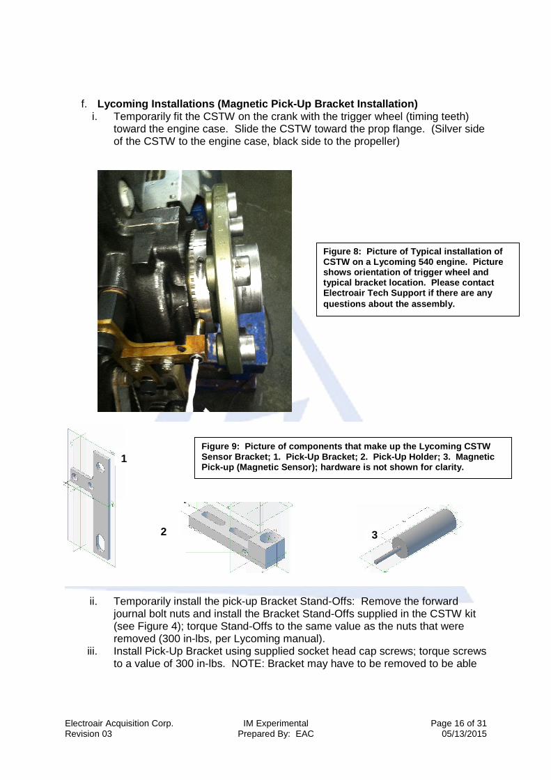
f. Lycoming Installations (Magnetic Pick-Up Bracket In stallation) i. Temporarily fit the CSTW on the crank with the trigger wheel (timing teeth)
toward the engine case. Slide the CSTW toward the prop flange. (Silver side of the CSTW to the engine case, black side to the propeller)
ii. Temporarily install the pick-up Bracket Stand-Offs: Remove the forward journal bolt nuts and install the Bracket Stand-Offs supplied in the CSTW kit (see Figure 4); torque Stand-Offs to the same value as the nuts that were removed (300 in-lbs, per Lycoming manual).
iii. Install Pick-Up Bracket using supplied socket head cap screws; torque screws to a value of 300 in-lbs. NOTE: Bracket may have to be removed to be able
Figure 8: Picture of Typical installation of CSTW on a Lycoming 540 engine. Picture shows orientation of trigger wheel and typical bracket location. Please contact Electroair Tech Support if there are any questions about the assembly.
1
2
Figure 9: Pic ture of components that make up the Lycoming CSTW Sensor Bracket; 1. Pick-Up Bracket; 2. Pick-Up Ho lder; 3. Magnetic Pick-up (Magnetic Sensor); hardware is not shown fo r clarity.
3

Electroair Acquisition Corp. IM Experimental Page 17 of 31 Revision 03 Prepared By: EAC 05/13/2015
to install Pick-Up Holder; once bracket is in place and will not be removed, safety wire the cap screws in place.
iv. Temporarily install the Sensor Holder on to the Pick-Up Bracket; leave the nuts loose enough so the Sensor Holder can slide back and forth to obtain the correct position.
v. Position the CSTW so that the magnetic pick-up (sensor) would be oriented correctly on the timing teeth on the CSTW.
vi. Rotate the CSTW and align the hole in the CSTW with the alignment tool (dowel/rivet assembly). Complete this by inserting the shaft of the pop rivet through the hole in the wood dowel. Place this assembly into the hole of the Pick-Up Holder (dowel/rivet assembly simulates a magnetic pick-up and pop rivet will serve as an alignment pin). Hold it in place.
vii. While holding these pieces together, mark the position of the Pick-Up Holder on to the Pick-Up Bracket.
viii. After marking the location of the Pick-Up Holder, remove the Pick-Up Bracket and Holder assembly; tighten the fasteners so the Pick-Up Holder is in the correct location on the bracket.
ix. Re-attach completed magnetic Pick-Up Bracket/Holder assembly to the engine (install bracket assembly on stand-offs); tighten fasteners to the recommended torque values found in the engine overhaul specifications. Verify that screws holding bracket to stand-offs ha ve been secured using safety wire.
g. Verify that the master switch is off and battery is disconnected. Verify that the mag switch is off and the mag is properly groun ded. ALWAYS STAY OUT OF THE PROPOLLER ARC!
h. Rotate the engine until number one cylinder is on Top Dead Center (TDC). i. Loosen the CSTW and rotate it until the alignment pin (remember the dowel/pop
rivet assembly which is still in the pick-up holder) lines up with the hole in the CSTW. The alignment pin can be used to lock the CSTW position. This should place the trailing edge of the 11 th tooth past the two missing teeth directly under the center of where the magnetic pick-up will go. Reference Figure 6 for sensor alignment and positioning. If this is not correct, return to step “d” or “e” (depending on your engine make) and repeat.
Figure 10: Crank Shaft Trigger Wheel Positioning

Electroair Acquisition Corp. IM Experimental Page 18 of 31 Revision 03 Prepared By: EAC 05/13/2015
j. Remove CSTW and apply Loctite (Loctite # 242) to the crank shaft side of CSTW and to the two socket head cap screws.
k. Carefully replace the collar to the crank shaft and line up using the alignment pin as described in 3h. The alignment pin will help hold the CSTW in position.
l. Torque the cap screws on the CSTW to 20-25 inch-pounds. Be very careful that the gap between the two collar halves remains equal on both sides. If this gap is not held constant, the CSTW will not be concentric around the crank shaft and the timing pick-up will not function properly. CAUTION: Do not tighten the CSTW screws to the point that there is no gap between the collar halves. This means that the screws are over torqued, the aluminum collar stretched, and the CSTW will need replacing.
m. Route the magnetic pick-up wire harness up the center of the engine case and then on top of the engine. Use cable ties as necessary to secure routing. Do not route near spark plug wires. Do not tie wrap to ignition leads.
n. Remove the dowel/pop rivet assembly from the pick-up holder and install the magnetic pick-up. Using a feeler gage or equivalent, set the gap to 0.024 inches. Once the gap between the timing teeth and the magnetic pick-up is set, apply a thin coating of Loctite #242 to the set-screws, insert them into the pick-up holder, and tighten them down. NOTE: The tip of the sensor is a “Chisel Point”; this chisel must be positioned so that it is perpendicular to the plane of the trigger, or so that the chisel is parallel to the line of flight.
CSTW Installation - Exploded View; NOT TO SCALE
Magnetic Pick-Up Holder pre-drilled for rivets
Magnetic Pick-Up
Pick-Up Bracket('Y' Bracket)
Alignment Hole
Cap Screw,2 places
Rivet holes for mounting MagneticPick-Up Holder; locate & drill perinstallation manual instructions.
CSTW Assembly
Prop Flange
Figure 11: CSTW Installation – Exploded View; NOT TO SCALE
6. Installation of EIS Controller and Coil Pack
a. Select appropriate locations for the EIS Controller and Coil Pack to be mounted.

Electroair Acquisition Corp. IM Experimental Page 19 of 31 Revision 03 Prepared By: EAC 05/13/2015
i. Remove harness attached to EIS Controller and set aside for later installation. ii. Install the EIS Controller where temperatures will not exceed 150°F. Because
of this, Electroair recommends that the EIS Controller be mounted on the cockpit side of the firewall with the shortest practical distance from the coil pack for the wiring harness runs. Dimensions for the controller are laid out below:
Figure 12: EIS Controller Dimensions
iii. The most common place to mount the coil pack is on the engine side of the
firewall. Try to locate the unit in a position to keep the spark plug wires as short as possible and not interfere with other components or create maintenance difficulties in the future. Additionally, the coil pack should be on a flat surface that is grounded. The unit also comes with a ground wire which will be installed in section 8. Coil Pack dimensions are below:
Electroair Acquisition Corp. IM Experimental Page 20 of 31 Revision 03 Prepared By: EAC 05/13/2015
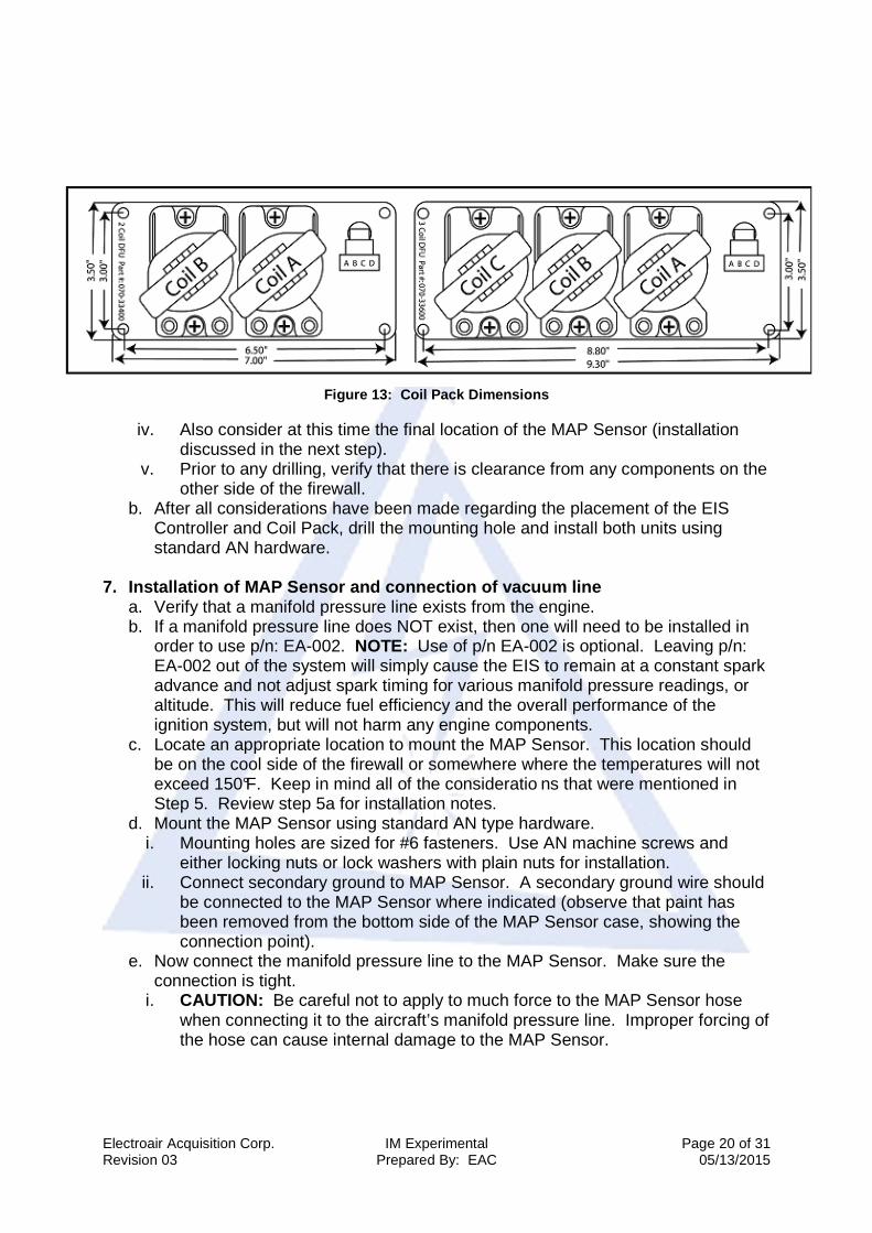
Figure 13: Coil Pack Dimensions
iv. Also consider at this time the final location of the MAP Sensor (installation
discussed in the next step). v. Prior to any drilling, verify that there is clearance from any components on the
other side of the firewall. b. After all considerations have been made regarding the placement of the EIS
Controller and Coil Pack, drill the mounting hole and install both units using standard AN hardware.
7. Installation of MAP Sensor and connection of vacuum line
a. Verify that a manifold pressure line exists from the engine. b. If a manifold pressure line does NOT exist, then one will need to be installed in
order to use p/n: EA-002. NOTE: Use of p/n EA-002 is optional. Leaving p/n: EA-002 out of the system will simply cause the EIS to remain at a constant spark advance and not adjust spark timing for various manifold pressure readings, or altitude. This will reduce fuel efficiency and the overall performance of the ignition system, but will not harm any engine components.
c. Locate an appropriate location to mount the MAP Sensor. This location should be on the cool side of the firewall or somewhere where the temperatures will not exceed 150°F. Keep in mind all of the consideratio ns that were mentioned in Step 5. Review step 5a for installation notes.
d. Mount the MAP Sensor using standard AN type hardware. i. Mounting holes are sized for #6 fasteners. Use AN machine screws and
either locking nuts or lock washers with plain nuts for installation. ii. Connect secondary ground to MAP Sensor. A secondary ground wire should
be connected to the MAP Sensor where indicated (observe that paint has been removed from the bottom side of the MAP Sensor case, showing the connection point).
e. Now connect the manifold pressure line to the MAP Sensor. Make sure the connection is tight.
i. CAUTION: Be careful not to apply to much force to the MAP Sensor hose when connecting it to the aircraft’s manifold pressure line. Improper forcing of the hose can cause internal damage to the MAP Sensor.
Electroair Acquisition Corp. IM Experimental Page 21 of 31 Revision 03 Prepared By: EAC 05/13/2015
ii. If a Manifold Pressure gauge is installed, a “T” fitting can be placed into the manifold pressure line that is feeding the Manifold Pressure gauge.
1.) The hose coming from the MAP Sensor is MIL-H-5593 type hose commonly used in vacuum line installation (either Aeroquip 306 or Stratoflex 193). This size is -3 or 3/16 inch ID.
2.) Connect to the manifold pressure line with either standard fittings or other appropriate fittings for this application.
3.) Verify that all connections and lines are tight and secure. iii. If a Manifold Pressure gauge is not installed and a new manifold pressure line
was created, connect that new line directly to the hose coming from the MAP Sensor using standard fittings. The hose coming from the MAP Sensor is MIL-H-5593 type hose commonly used in vacuum line installation (either Aeroquip 306 or Stratoflex 193). This size is -3 or 3/16 inch ID.
8. Spark Plugs and Spark Plug Wire Harness
a. Install the spark plugs that will be connected to the Electronic Ignition System. Electroair recommends using new aircraft spark plugs. If re-using the old spark plugs, make sure that they are clean.
i. Optional: Electroair has approved wide gap aircraft spark plugs for use the Electroair Electronic Ignition Systems. These spark plugs are manufactured with the wider air gap Electroair recommends be used with the Electronic Ignition Systems. These Electroair spark plugs are not included in the standard EIS Kit. These plugs are only approved to be used with Electroair’s Electronic Ignition Systems. The Electroair part numbers and descriptions for these plugs are below: 1. EARHB32E Massive Electrode Spark Plug: This plug is Electroair’s
version of the standard RHM32E spark plug. The EARHB32E plug is manufactured with a 0.036 inch air gap. The EARHB32E spark plug can be installed on the engines that are approved for the RHB32E spark plug, but can only be operated by an Electroair EIS. Please contact Electroair or one of our distributors for current pricing and availability of this spark plug.
2. EARHB32S Single Fine Wire Spark Plug: This plug is Electroair’s version of the standard RHB32S spark plug. The EARHB32S is manufactured with a 0.036 inch air gap. The EARHB32S spark plug can be installed on the engines that are approved for the RHB32S spark plug, but can only be operated by an Electroair EIS. Please contact Electroair or one of our distributors for current pricing and availability of this spark plug.
3. EAREM37HE Massive Electrode Spark Plug: This plug is Electroair’s version of the standard REM37BY spark plug. The EAREM37HE plug is manufactured with a 0.036 inch air gap. The EAREM37HE spark plug can be installed on the engines that are approved for the REM37BY spark plug, but can only be operated by an Electroair EIS. Please contact Electroair or one of our distributors for current pricing and availability of this spark plug.
4. EARHM38SE Single Fine Wire Spark Plug: This plug is Electroair’s version of the standard RHM38S spark plug. The EARHM38SE is
Electroair Acquisition Corp. IM Experimental Page 22 of 31 Revision 03 Prepared By: EAC 05/13/2015
manufactured with a 0.036 inch air gap. The EARHM38SE spark plug can be installed on the engines that are approved for the RHM38S spark plug, but can only be operated by an Electroair EIS. Please contact Electroair or one of our distributors for current pricing and availability of this spark plug.
ii. For all other aircraft spark plugs, Electroair recommends that opening the gap of the spark plugs to 0.028 - 0.036 inches. For Lycoming engines, Electroair suggests using the REM37BY (or UREM37BY) spark plug because they are the easiest to gap. Check the engine application data to verify that these plugs can be used in the engine. CAUTION: Be careful when gapping all other plugs than the REM37BY (UREM37BY) plug, because the outer electrode can become over-stressed and break. If any problems arise with plug selection, please contact Electroair.
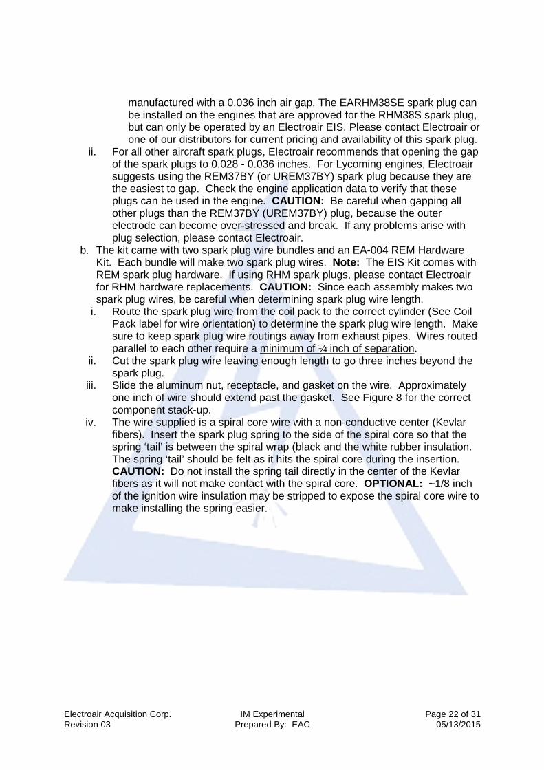
b. The kit came with two spark plug wire bundles and an EA-004 REM Hardware Kit. Each bundle will make two spark plug wires. Note: The EIS Kit comes with REM spark plug hardware. If using RHM spark plugs, please contact Electroair for RHM hardware replacements. CAUTION: Since each assembly makes two spark plug wires, be careful when determining spark plug wire length.
i. Route the spark plug wire from the coil pack to the correct cylinder (See Coil Pack label for wire orientation) to determine the spark plug wire length. Make sure to keep spark plug wire routings away from exhaust pipes. Wires routed parallel to each other require a minimum of ¼ inch of separation.
ii. Cut the spark plug wire leaving enough length to go three inches beyond the spark plug.
iii. Slide the aluminum nut, receptacle, and gasket on the wire. Approximately one inch of wire should extend past the gasket. See Figure 8 for the correct component stack-up.
iv. The wire supplied is a spiral core wire with a non-conductive center (Kevlar fibers). Insert the spark plug spring to the side of the spiral core so that the spring ‘tail’ is between the spiral wrap (black and the white rubber insulation. The spring ‘tail’ should be felt as it hits the spiral core during the insertion. CAUTION: Do not install the spring tail directly in the center of the Kevlar fibers as it will not make contact with the spiral core. OPTIONAL: ~1/8 inch of the ignition wire insulation may be stripped to expose the spiral core wire to make installing the spring easier.

Electroair Acquisition Corp. IM Experimental Page 23 of 31 Revision 03 Prepared By: EAC 05/13/2015
Figure 14: Spark Plug Wire Hardware Assembly
v. To finish the connection, install the spark plug end of the wire first. This
prevents the spark plug wire from twisting as the spark plug nut is tightened. CAUTION: Do not over-tighten the spark plug nut as this may cause separation of the core of the wire. Tighten the spark plug nut to a torque value of 95 in-lb
vi. Attach the other end of the spark plug wires to the coil pack at their appropriate coil tower. NOTE: When inserting the 90° boot over each tower on the coil pack, an audible “SNAP” should be heard when the wire is properly installed onto each tower. If this snap is not heard, remove the boot from the tower and repeat this step until the “SNAP” is heard.
vii. Coil towers are numbered on the coil pack: 1, 2, 3, and 4. Because of the nature of the system, coil towers 1 & 2 will fire simultaneously and then coil towers 3 & 4 will fire simultaneously.
viii. For Lycoming engines, hook-up the spark plug wires according to the Spark Plug Wire Hook-Up Chart
ix. The coil towers should be oriented towards the same side of the engine as the cylinders – this should make spark plug wire hook-up easier.

Electroair Acquisition Corp. IM Experimental Page 24 of 31 Revision 03 Prepared By: EAC 05/13/2015
B2 B1 A2 A1Coil Tower ID's for 4-cylinder
C2 C1 B2 B1 A2 A1
Coil Tower ID's for 6-cylinder
Figure 15: Coil Pack Tower IDs
Spark Plug Wire Hook-Up Chart Engine Type Coil A Coil B Coil C Coil D Lycoming 4cyl Cyl 1 to A1
Cyl 2 to A2 Cyl 3 to B1 Cyl 4 to B2
TCM 4cyl Cyl 1 to A1 Cyl 2 to A2
Cyl 3 to B1 Cyl 4 to B2
Rotorway 4cyl Cyl 1 to A1 Cyl 2 to A2
Cyl 3 to B1 Cyl 4 to B2
VW 4cyl Cyl 1 to A1 Cyl 2 to A2
Cyl 3 to B1 Cyl 4 to B2
Franklin 6cyl Cyl 1 to A1
Cyl 2 to A2 Cyl 4 to B1 Cyl 3 to B2
Cyl 5 to C1 Cyl 6 to C2
Lycoming 6cyl Cyl 1 to A1 Cyl 2 to A2
Cyl 4 to B1 Cyl 3 to B2
Cyl 5 to C1 Cyl 6 to C2
TCM 6cyl Cyl 1 to A1 Cyl 2 to A2
Cyl 5 to B1 Cyl 6 to B2
Cyl 3 to C1 Cyl 4 to C2
Chevy 2.8 Cyl 1 to A1
Cyl 4 to A2 Cyl 2 to B1 Cyl 5 to B2
Cyl 3 to C1 Cyl 6 to C2

Electroair Acquisition Corp. IM Experimental Page 25 of 31 Revision 03 Prepared By: EAC 05/13/2015
9. Wiring Hook-Up
a. Verify that the master switch is off and battery is disconnected. b. The electrical connections that will be made are as follows:
i. Ground for Coil Pack ii. Spark Plugs iii. Timing sensor (either from the MTH or the CSTW). iv. Coil Pack v. Switched (or keyed) Power for EIS Controller
c. NOTE: Determine whether or not you are going to use a key switch or toggle switch for operating the EIS. If you are going to use a toggle switch, proceed with installation. If you are going to use a key switch, contact Electroair (517-552-9390 or [email protected]) to determine if the harness has been modified to work with a key switch. In order to use a key switch with an Electroair ignition, a Key Switch Lead must be added to this harness at the factory. This Key Switch Lead will replace the P-Lead for the right hand magneto at the key switch. Also, verify the key switch is functioning properly. A worn or old key switch will arc internally and cause the EIS to malfunction. If in doubt, replace the key switch.
d. Notes: The main harness is not completely assembled so it can be installed through tight clearances such as a hole in the fire wall. Terminal ends for the MAP Sensor and Timing Pick-up have been supplied. A supply terminations for switches, circuit breakers, and the bus bar are necessary. The main harness has been tied off into five separate bundles. Each bundle is labeled 1,2,3,4, & 5. Work with each harness bundle separately. A wiring diagram with pin-out information has been supplied in this section for reference. CAUTION: Follow these wiring instructions very carefully to insure a correct hook-up of the EIS. Skipping ahead or taking short cuts increases the risk of an incorrect installation and either a poor performing EIS or the possibility of damaging equipment. Please call us if you have any questions.
e. Connect the Coil Pack ground wire to an airframe or battery (preferred) ground. The Coil Pack ground wire is the black wire that is fastened on the Coil Pack base plate. This wire will need to be appropriately terminated at the ground connection (a connector is not provided for this). CAUTION: The Coil Pack MUST be grounded. Failure to ground the Coil Pack may result in SEVERE ELECTRICAL SHOCK! Also, a poorly grounded Coil Pac k may result in poor engine performance and can cause ENGINE DAMAGE .
f. Verify that the screws holding the coils and ground wire in place are tightened and securely in place.
Buick 3.0/3.8 Cyl 1 to A1 Cyl 4 to A2
Cyl 3 to B1 Cyl 6 to B2
Cyl 2 to C1 Cyl 5 to C2
Ford 2.8 Cyl 1 to A1 Cyl 5 to A2
Cyl 3 to B1 Cyl 4 to B2
Cyl 2 to C1 Cyl 6 to C2
Lycoming 8cyl Cyl 1 to A1
Cyl 2 to A2 Cyl 7 to B1 Cyl 8 to B2
Cyl 5 to C1 Cyl 6 to C2
Cyl 3 to D1 Cyl 4 to D2

Electroair Acquisition Corp. IM Experimental Page 26 of 31 Revision 03 Prepared By: EAC 05/13/2015
g. Connect the EIS Controller harness assembly to the EIS Controller. You will begin routing the various harness bundles from here.
h. Route harness bundle #1 to the MAP Sensor from the controller. i. Route harness to MAP Sensor. ii. Trim and terminate the bundle #1 with the enclosed Molex pins and
connector. The connections are as follows: Gray w/ Red Stripe (PWR) in Cavity 1, Black w/ White Stripe (GND) in Cavity 2, and Green (MAP Signal) to Cavity 3 (Note: connector cavities are marked with one line for Cavity 1, two lines for Cavity 2 & three lines for Cavity 3).
iii. Connect now-terminated bundle #1 to MAP Sensor and secure bundle with cable ties.
i. Route harness bundle #2 to the Timing Sensor (either the MTH for 4-cylinders or the CSTW for 6-cylinders).
i. If the Timing Sensor has been installed and/or routed correctly, you will have a black, three-way connector coming from the magnetic pick-up. Route bundle #2 to that three-way connector.
ii. Bundle #2 has already been terminated to go into the appropriate mating connector body that will attach to the magnetic pick-up harness. Once bundle #2 has been routed past any tight clearances (such as a hole in the fire wall), install the supplied connector body to the terminated wires. The wires go into the following connector cavities: 1. Red wire goes into cavity ‘A’ 2. Black wire goes into cavity ‘B’ 3. Bare wire goes into cavity ‘C’
iii. You will hear an audible ‘click’ when the terminated wires have been properly installed into the connector body and the wire should not be able to be pulled out.
iv. Loop any excess wire and cable tie or clamp the loop to a convenient location that does not interfere with any components (a location on the inside of the firewall is suggested).
v. Connect bundle #2 (now terminated with a connector body) to the connector from the magnetic pick-up. Verify that the connection is secure.
j. Route harness bundle #3 to the Coil Pack. i. Separate the ‘Red w/ White Stripe’ wire from the other wires that are bundled
(gray wrap) and terminated with a four-way connector (this wire is for power). ii. Loop any excess wire of the gray bundle and cable tie or clamp the loop to a
convenient location that does not interfere with any components (a location on the inside of the firewall is suggested).
iii. Connect the four-way connector to the mating connector on the Coil Pack. iv. Route the ‘Red w/ White Stripe’ wire through a 10 amp breaker to the
Essential Bus Bar. Trim and terminate as required. k. Toggle Switch Set-Up: Route harness bundle #4 to Essential Bus Bar for switch
termination. (For Key Switch set-up, see step 8.l.). i. Trim & Terminate the ‘Yellow’ wire to a panel mounted switch that is protected
with a 2 amp breaker. Label panel mounted switch “Electronic Ignition

Electroair Acquisition Corp. IM Experimental Page 27 of 31 Revision 03 Prepared By: EAC 05/13/2015
System”, and proper “ON/OFF” orientation. This switch should be a SPST switch.
ii. Connect the 2-amp breaker to Essential Bus Bar. l. Key Switch Set-Up: Route harness bundle #4 to Essential Bus Bar for circuit
breaker termination. Note: EIS Controller harness must have factory installed Key Switch Lead (white wire) in bundle #4; this insures proper operation of the Key Switch – call us if you have any questions.
i. Terminate the ‘Yellow’ wire to a 2 amp circuit breaker. ii. Connect 2-amp circuit breaker to Essential Bus Bar. iii. Remove right hand magneto P-Lead wire from Key Switch. iv. Connect white, shielded wire to key switch where right hand magneto P-Lead
would connect. Connect shield to ground terminal. m. Bundle #5 contains two extra outputs for an electric tach and a spark advance
meter (make sure to connect the ground wire from the spark advance meter to a common ground). This bundle should be looped and tied to an appropriate place inside the cockpit for later use. Alternatively, bundle #5 can trimmed out of the harness connector if those options will not be used. Wiring diagrams for the electric tach and/or spark advance meter are supplied with Electroair option kits #EA-009, electric tach and #EA-010, Spark Advance Meter. Please contact the factory for more details.
n. Route Engine Block Ground wire harness to the engine block ground connection point and then connect to ‘pig-tail’ on EIS Controller.
Electroair Acquisition Corp. IM Experimental Page 28 of 31 Revision 03 Prepared By: EAC 05/13/2015
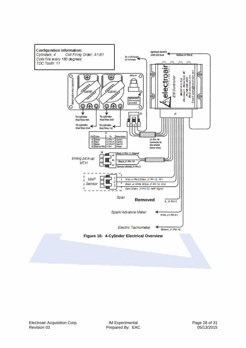
Figure 16: 4-Cylinder Electrical Overview
Removed
Electroair Acquisition Corp. IM Experimental Page 29 of 31 Revision 03 Prepared By: EAC 05/13/2015
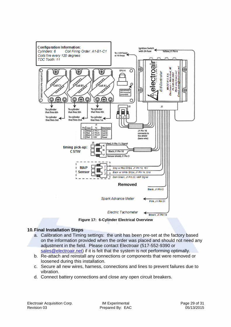
Figure 17: 6-Cylinder Electrical Overview
10. Final Installation Steps
a. Calibration and Timing settings: the unit has been pre-set at the factory based on the information provided when the order was placed and should not need any adjustment in the field. Please contact Electroair (517-552-9390 or [email protected]) if it is felt that the system is not performing optimally.
b. Re-attach and reinstall any connections or components that were removed or loosened during this installation.
c. Secure all new wires, harness, connections and lines to prevent failures due to vibration.
d. Connect battery connections and close any open circuit breakers.
Removed

Electroair Acquisition Corp. IM Experimental Page 30 of 31 Revision 03 Prepared By: EAC 05/13/2015
e. Recover all tools that may have been used (tools ‘floating’ around inside the aircraft are dangerous).
f. Proceed to the AFMS and perform a test run-up before flying.
11. Installation Options available from Electroair a. P/N: EAREM37HE. Electroair’s Massive Electrode Spark Plug. This plug is
Electroair’s version of the standard REM37BY spark plug manufactured with a 0.036 inch air gap and has been approved for use with only Electroair’s electronic ignition systems. These plugs come with the increased air gap Electroair recommends be used with our systems and eliminates the time and headache of re-gapping standard aircraft spark plugs. These Electroair spark plugs are not included in the standard EIS Kit. Please contact Electroair or one of our distributors for current pricing and availability of this spark plug.
b. P/N: EARHM38SE. Electroair’s Single Fine Wire Spark Plug. This plug is Electroair’s version of the standard RHM38S spark plug manufactured with a 0.036 inch air gap and has been approved for use with only Electroair’s electronic ignition systems. These plugs come with the increased air gap Electroair recommends be used with our systems and eliminates the time and headache of re-gapping standard aircraft spark plugs. These Electroair spark plugs are not included in the standard EIS Kit. Please contact Electroair or one of our distributors for current pricing and availability of this spark plug.

Electroair Acquisition Corp. IM Experimental Page 31 of 31 Revision 03 Prepared By: EAC 05/13/2015
Glossary and Abbreviations: AD(s) – Airworthiness Directive(s) AFM – Aircraft Flight Manual AFMS – Aircraft Flight Manual Supplement ALS – Aircraft Limitations Section AML – Approved Model List APU – Auxiliary Power Unit BTDC – Before Top Dead Center CFR – Code of Federal Regulations CSTW – Crank Shaft Trigger Wheel EIS – Electronic Ignition System FAA – Federal Aviation Administration Ignition Timing – is the process of setting the angle relative to piston position and crankshaft angular velocity that a spark will occur in the combustion chamber near the end of the compression stroke. MAG – magneto MAP – Manifold Absolute Pressure May/Should – an optional requirement MTH – Mag Timing Housing Must/Shall – a mandatory requirement RPM – Revolutions per Minute POH – Pilot’s Operating Handbook STC – Supplemental Type Certificate TDC – Top Dead Center
Log of Revisions: Revision Date of Revision Description of Revision Approved by Date of Approval
00 Skipped
01 Initial Release JDR
02 09/18/2014 ECO 1116-0043 12/01/2014
03 05/13/2015 ECO 1116-0117 05/13/2015