experiments and analysis of the traditional wood
TRANSCRIPT

The 14th
World Conference on Earthquake Engineering October 12-17, 2008, Beijing, China
Experiments and Analysis of the Traditional Wood Structural Frame Y.W. Lee1, S.G. Hong2, B.S. Bae3, J.K Hwang4, N.H. Kim5 and S.J. Jung6
1 Professor, Dept. of Architecture and Building Engineering , Kunsan National University,Junbuk, Korea
2 Professor, Dept. of Architecture, Seoul National University, Seoul, Korea 3 Director, National Research Institute of Cultural Heritage, Deajeon, Korea
4 Professor, Department of Traditional Architecture, National University of Cultural Heritage, Korea 5 Senior Researcher, Ph.D, Korea bridge design and engineering research center
6 Professor, Department of Architectural Engineering, Hannam Uiversity, Deajeon, Korea Email: [email protected]
ABSTRACT :
To find the behavior of a wooden frame of a traditional structure system, experimental researches are performed. A temple(Deawoong-Jeon) of Bongjeong-sa built in the early stage of the tenth century is considered as a typical model. The interior frame of the temple has two exterior short columns and one inside high column called as Goju(high column) in crossbeam direction. At the top of the exterior column, Gongpo(Corbel bracket) is located to transfer the beam loads into columns. Subassembly of 1/2 scaled Gongpo and Goju frame is constructed and tested to find the force-displacement characteristics. Also a 1/2 scaled structural frame is constructed and tested for the comparison with analysis. From subassemblies of Gongpo and Goju frame, analytical models are proposed with shear and rotational spring, of which coefficients are obtainedfrom the experiments. The envelope curve of each spring is presented by bilinear model. With the proposed model, a push-over analysis is performed and compared with the experimental results of the full interior frame. The force-displacement of the analysis of proposed model shows a good correspondence with that of the experiment within 2% story drift.
KEYWORDS: Experiment, Pushover Analysis, Traditional wood frame, Corbel bracket(Gongpo)
1. INTROCUCTION The main building Deawoong-jeon of Bongjeong-sa(temple) located in the Andong-city in Korea was originally built in the early stage of the tenth century. It was rebuilt several times from first construction to now. In 1809, it was reconstructed on a large scale and a large part of the present appearance(Fig. 1) is the result of that reconstruction. Until several years ago, the partial repair had been advancing for roof, decorative painting andwooden floor. The latest total repair was performed in 2000 and it was classified as the national treasure of Korea. Deawoong-jeon has front exterior frames which have 3 spans and are perpendicular to a large crossbeam direction, as shown in Fig. 1 and 2. In the direction of large crossbeam, it has two side and two internal frames. In all frames, the column is just placed on a foundation stone without mechanical fasteners. The frame is composed by columns and connecting beams. The connecting beams are connected by rake joints located overthe columns, taking advantages of the reinforcement provided by the surrounding slot (Fig.3). The architraves which are placed bracket sets are located on column-connecting beam joints. All bracket sets, composed of soro (blocks) and cheomcha (arms), are located on architraves (Fig. 4), of which the main role is to transfer the roof dead load to the foundation stone. Its basic structural system consists of a column and lintel beam connected by friction joints and Gongpo(bracket set). The Gongpo system is a unique system of brackets placed on top of columns to provide additional supportto beams or overhanging eaves. Some static and dynamic experiments (Hwang, 2008) are executed to find the characteristics of the system. In this paper the experiments of the internal frame in direction of main cross beam are introduced. In the internal frame(Fig. 12) in the direction of main crossbeam, Gongpo(Fig. 6) is located at the top of an exterior column and a special joint at Goju(high column) shown in Fig. 7, which is connected by sanji(wood nail) with beams. These joints cause complex structural behaviors because forces are transmitted through contact areas and slips are occurred between the elements.

The 14th
World Conference on Earthquake Engineering October 12-17, 2008, Beijing, China A numerical analysis with FEM is not easy to model including these joints and not practical because it requiresmuch time. Macroscopic spring models are efficient for structural analysis for complex joints (Fang, 2001). In this paper, a simple macroscopic model with rotation and shear springs will be proposed, based on the experiments of sub-assembled frames and verified by the comparison with the full frame experiments (Fig. 12)
Figure 1 Exterior front view Figure 2 Base floor plan
Figure 3 Connecting beam & slot Figure 4 Soro(block) and cheomcha(arm)
Figure 5 Flowchart of experiment and Analysis
2. Experiments Experiments of a full frame (Fig. 12) and two subassemblies (Fig. 6 and 9) are executed in different laboratories. Through two subassembly experiments of Gongpo and Goju, joint behaviors are studied and analytical models and its spring coefficients are proposed for a numerical analysis, as shown if the flowchart in Fig. 5. Pushover analysis is carried out for the frame and compared with the experimental results for theverification. In this chapter the experiment and results of subassemblies and the full frame are described. All experimental models are constructed in half scale with Korean red pine wood. Gravity loads are applied inGongpo subassembly and the interior frame experiments. Though all columns are elected upon a stone base, a hinge is used at the bottom of a column to avoid uncertainty of boundary condition in experiments.
Frame Experiment Subassembly Exp.
Spring coefficient Comparison
Num. Analysis
Pushover Analysis
Joint force-disp. Frame force-disp. Macro Model

The 14th
World Conference on Earthquake Engineering October 12-17, 2008, Beijing, China 2.1 Subassembly experiments 2.1.1 Gongpo subassembly In the interior frame (Fig.12) there are 3 columns and Gongpo is located on two external columns and oneinternal column called Goju is higher than external columns. The location of a main crossbeam is 1.512m above the base hinge and span length is 2.0m. Constructed modes does not include roof which produces heavy dead loads, coming from thick soils, layered woods and roof tiles. To consider roof dead loads, steel blocks are applied at purlins same as in Fig.13. Applied dead loads are the same as in Table 2.1 at points (1), (2), (3) in Fig 12.
Figure 6 Experimental model of Gongpo subassembly
-800
-600
-400
-200
0
200
400
600
800
1000
1200
-80 -60 -40 -20 0 20 40 60 80
2 step 3 step
4 step 5 step
6 step 7 step
8 step
Force(N)
Disp(mm)
1% 2% 3% 4% story drift
-4% - 3% - 2% -1%storydrift
y
x
θ1
θ2
θ3
rotation spring
(+) load
shear spring
Figure 7 Force-displacement of Gongpo subassembly. Figure 8 Macro model of Gongpo subassembly
Lateral forces are applied at the center of main crossbeam with displacement control unto 4% story drift.Loading is composed of total 8 steps which have 3 cycles per each step. 1st and 2nd step has equally 0.5% story drift and 0.5% story drift is increasing from 3rd to 7th steps. At the last 8th step 4% story drift is applied.
12
13
16
2
1
3
11
4
6
89
7 14
5
15
17
상대 XY변위
절대 XY변위
힌지
LM 가이드
대량
지지대
Y
X
힌지
평주
SWIVEL HEAD
ACTUATOR
2000
1512
주두
Number = measuring point of displacement
hinge
LM guidemain crossbeam
capital
column Reaction support
hinge
The 14th
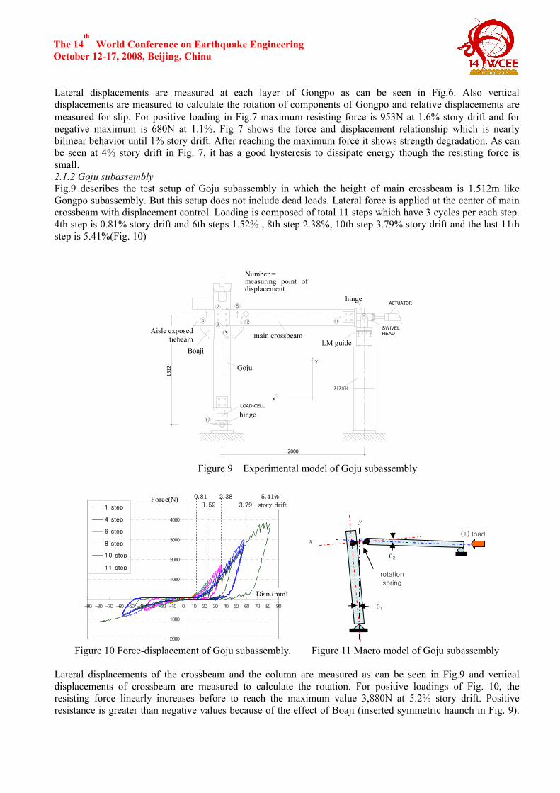
World Conference on Earthquake Engineering October 12-17, 2008, Beijing, China Lateral displacements are measured at each layer of Gongpo as can be seen in Fig.6. Also verticaldisplacements are measured to calculate the rotation of components of Gongpo and relative displacements are measured for slip. For positive loading in Fig.7 maximum resisting force is 953N at 1.6% story drift and fornegative maximum is 680N at 1.1%. Fig 7 shows the force and displacement relationship which is nearly bilinear behavior until 1% story drift. After reaching the maximum force it shows strength degradation. As can be seen at 4% story drift in Fig. 7, it has a good hysteresis to dissipate energy though the resisting force issmall. 2.1.2 Goju subassembly Fig.9 describes the test setup of Goju subassembly in which the height of main crossbeam is 1.512m like Gongpo subassembly. But this setup does not include dead loads. Lateral force is applied at the center of main crossbeam with displacement control. Loading is composed of total 11 steps which have 3 cycles per each step.4th step is 0.81% story drift and 6th steps 1.52% , 8th step 2.38%, 10th step 3.79% story drift and the last 11thstep is 5.41%(Fig. 10)
Figure 9 Experimental model of Goju subassembly
-2000
-1000
0
1000
2000
3000
4000
5000
-90 -80 -70 -60 -50 -40 -30 -20 -10 0 10 20 30 40 50 60 70 80 90
1 step
4 step
6 step
8 step
10 step
11 step
Force(N)
Disp.(mm)
0.81
1.52
2.38
3.79
5.41%
story drift
Figure 10 Force-displacement of Goju subassembly. Figure 11 Macro model of Goju subassembly
Lateral displacements of the crossbeam and the column are measured as can be seen in Fig.9 and verticaldisplacements of crossbeam are measured to calculate the rotation. For positive loadings of Fig. 10, the resisting force linearly increases before to reach the maximum value 3,880N at 5.2% story drift. Positive resistance is greater than negative values because of the effect of Boaji (inserted symmetric haunch in Fig. 9).
2000
절대 XY변위
상대 XY변위
17
11
2
3
5
4 12
1
1512
SWIVEL HEAD13
흰지
지지대
ACTUATOR
고주
대량
ML-가이드
LOAD-CELL
흰지
Y
X
퇴량
보아지
Number = measuring point of displacement
hinge
LM guide
Goju
hinge
Boaji
main crossbeam Aisle exposed tiebeam
x
y
θ1
θ2
(+) load
rotation
spring

The 14th
World Conference on Earthquake Engineering October 12-17, 2008, Beijing, China Also negative force-displacement relationship shows linear. Hysteretic loop (Fig.10) shows pinching effectbecause of the gap between the column and the main crossbeam. 2.2 Frame experiment The setup of internal frame experiment is shown in Fig.12; the location of crossbeam center is 2.49m above the base hinge, which is different from that of subassemblies. The span length of the left beam is 1.494m and right span is 3.494m. For in-plane behavior of specimen, 3 rollers are used at main crossbeam perpendicular to the loading direction. Because this model does not include the roof, steel blocks are applied at purlin to simulate the dead load of roof (Fig.13) like Gongpo subassembly. Applied steel block loads are listed in Table 2.1, which is calculated based on influenced loading areas. The load at the exterior roof purlin is the greatest because the eave that is cantilevered from a external column is longer than that of an ordinary building as can be seen in Fig. 1.
Figure 12 Test model - 1/2 scaled interior frame Figure 13 Applied vertical loading block
Table 2.1 Applied dead loads at purlins Location Number
(1) Exterior
roof purlin
(2) Roof Purlin on column
(3) Interior
roof purlin
(4) Roof purlin
(5) Ridge purlin
(6) Roof
purlin.
(7) Interior
roof purlin
(8) Roof Purlin on column
(9) Exterior
roof purlinLoad(N) 13,450 232 4,671 7,902 4,620 7,902 4,671 232 13,450
Lateral load is applied at Goju, 1.898m above the base hinge (Fig. 12). Total 8 steps like Fig. 14 loads are applied from 0.5% to 4% story drift with 0.5% increment and each step is composed of static 4 cycles. Among4 cycles, the amplitude of first cycle is half of the last cycle of the previous step. Force and displacement relationship is not symmetric as in Fig. 15; positive maximum resistance is 2 kN andnegative value is 2.3 kN. For positive loading, yielding occurs at 1% story drift but for negative loading yielding occurs after 2% story drift and pinching can be seen after 5th step. Though the resisting force is small,the efficiency of dissipating energy is high. For each step, there is no stiffness and strength degrading after 3cycles of loading reversals. In positive loading direction, some spikes occurred, which mean some frictions are acting during loadings. In negative loading direction, pinching phenomenon can be seen after 5th step becauseof gaps between the column and the crossbeam.
372.0 372.0 750.0 1,000.0 1,000.0 750.0 372.0 372.0
813.8
393.4
189.0189.0
1,898.0 2,490.0
(1) (2)
(3)
(4) (6)
(7)(8)
(9)
(5)

The 14th
World Conference on Earthquake Engineering October 12-17, 2008, Beijing, China
-5%
-4%
-3%
-2%
-1%
0%
1%
2%
3%
4%
5%
1 STEP
Story drift ratio
2 STEP
3 STEP
4 STEP
5 STEP
6 STEP
7 STEP
8 STEP
-3
-2
-1
0
1
2
3
-100 -50 0 50 100
(+)
disp.(mm)
Force(kN)
1% 2% 3% 4%-4% -3% -2% -1%story drift
8 step765
Figure 14 Applied displacement-control load Figure 15 Force-displacement of interior frame
3. Numerical Model For the numerical analysis, the model of Gongpo is proposed as in Fig.8, which consists of 3 springs, a rotational spring at the capital of a column and a shear spring for the shear deformation of Gongpo and a rotational spring between the crossbeam and Gongpo. Spring coefficients are composed of 3 points; yielding, ultimate and ending points, to describe strength degrading like Fig.18. Strength degradation is calculated based on the ductility as Fig.17. All coefficients of Gongpo springs are listed in Table 3.1 For Gongpo spring, a numerical model is proposed like Fig.11, in which the column and the crossbeambehave as a rigid beam and a rotational spring is used between the column and the crossbeam. Rotationalspring coefficients are calculated and listed in Table 3.2. For positive loading, Gap element is used todescribe the gap between the crossbeam and the column as in Fig.19.
Table 3.1 Spring Coefficients of Gongpo spring rotation spring - Gongpo rotation spring - crossbeam shear spring - Gongpo (+) direction (-) direction (+) direction (-) direction (+) direction (-) direction rot. mom. rot. mom. rot. mom. rot. mom. disp. force disp. force (rad) (N-m) (rad) (N-m) (rad) (N-m) (rad) (N-m) (mm) (N) (mm) (N) Yielding (Dy,Fy) 0.56% 850 -0.82% -583 0.13% 572 -0.30% -1,220 2.45 760 -0.64 -560
Ultimate (Du,Fu) 1.28% 890 -1.80% -599 0.67% 1,076 -0.53% -1,430 5.3 876 -2.2 -590
Ending (De,Fe) 2.25% 725 -4.00% -300 0.72% 1,076 -0.57% -1,403 7.6 710 -5.79 -305
Ki (N-m/rad) 1.53×10⁵ 7.11×10⁴ 4.40×10⁵ 4.07×10⁵ 3.10×10² 8.75×10²
Kh (N-m/rad) 5.53×10³ 1.63×10³ 9.33×10⁴ 9.13×10⁴ 40.7 19.2
Hardening ratio 3.63% 2.30% 21.21% 22.45% 13.12% 2.20%
Duct1* 2.3 2.2 5.2 1.8 2.2 3.4
Rduct* 0.2 0.2 0.2 0.2 0.2 0.2
Kd (N-m/rad) 1.70×10⁴ 1.36×10⁴ 0 6.75×10⁴ 72.2 79.4
Duct2* 9.5 6.4 - 6.6 5.6 12.3 * Refer to Fig. 16

The 14th
World Conference on Earthquake Engineering October 12-17, 2008, Beijing, China
0
200
400
600
800
1000
0.0% 0.5% 1.0% 1.5% 2.0% 2.5%
rotaion
Mom
ent(N
-m)
experiment result
bilinear model withstrength degradng
Figure 16 Strength degrading Model Figure 17 Moment – rotation of spring r1
Table 3.2 Spring Coefficients of Goju spring
Figure 18 Moment – rotation of Goju spring
Figure 19 Macro model for analysis Figure 20 Yielding point in Pushover analysis 4. Analysis and comparison Using the proposed numerical model of Gongpo and Goju joint in chapter 3, the experimental frame of section 2.2 is modeled with springs like Fig.19. Gongpo spring is located at the external column and rotational spring is inserted between crossbeam and center column. Same as the experiment, the external load is applied at center column above 1.894m from the base hinge. Because the strength of column and crossbeam is higher than that of the spring of Gongpo, first yielding occurred at rotational spring of capital of the exterior column as shown in
(+) direction (-) direction
rot. mom. rot. mom.
(rad) (N-m) (rad) (N-m)
Initial (Di,Fi) 0.71% 0 0.00% 0
Yielding (Dy,Fy) 2.07% 2170 -1.50% -555
Ultimate (Du,Fu) 3.20% 3270 -3.11% -1,059
Ki (N-m/rad) 1.05×10⁵ 3.70×10⁴
Kh (N-m/rad) 9.73×10⁴ 3.13×10⁴
Hardening ratio, r 92.86% 84.61%
Gap(rad) 0.71 0.0
1.0
Rduct
Duct1 Duct2
Load factor
Ductility
0
500
1000
1500
2000
2500
3000
3500
0.0% 1.0% 2.0% 3.0% 4.0%
rotation
mom
ent(N
-m)

The 14th
World Conference on Earthquake Engineering October 12-17, 2008, Beijing, China Fig.20. Pushover analysis is executed with RUAUMOKO and compared with the experimental results in Fig.21. In case of positive loading with strength degrading model, a plastic hinge occurred firstly at the left rotationalspring of Gongpo and secondly at right the rotational spring of Gongpo and the analysis is stopped at 1.3%story drift because stiffness approaches zero. For negative loading, program stopped before 1% story drift. But in case of positive loading with bilinear modeling, the resistance is greater than the result of the experiment after 1% story drift. For negative loading, yielding occurred earlier than experiment and the resistance is less than the experimental value within 2.5% story drift. The analytical results show good agreements with the experiment within 2% story drift.
-3000
-2000
-1000
0
1000
2000
3000
-0.10 -0.08 -0.06 -0.04 -0.02 0.00 0.02 0.04 0.06 0.08 0.10
Displacement(m)
Force(N)
strength degrading model
bilinear model
experiment
1% 2% 3% 4% story drift-4% -3% -2% -1%
Figure 21 Force and displacement relation of analysis
5. Conclusion To study the behaviors of a wooden structure, experiments and analysis are performed for a temple(Deawoong-Jeon) of Bongjeong-sa built in the early stage of the tenth century. Firstly, 1/2 scaled subassembly of Gongpo and Goju frame are tested to find the force-displacement characteristics of joints. From the results analytical models are proposed and spring coefficients for numerical analysis are derived. With these resultspushover analysis is performed and compared with the experimental results of 1/2 scaled full frame. Theforce-displacement relationship of the analysis has a good correspondence with that of experiment within 2% story drift incase of using bilinear model. But the force-displacement relationship of the experiment is closer to that of the strength degradation model than that of bilinear model but the analysis of strength degradation model stops earlier because of stiffness approaches zero Even though the proposed macro model for a traditional wooden frame is compared with only one experimentof interior frame, it could give an possibility to analyze traditional wooden frames more efficiently than using general FEM. More researches are needed to find the stiffness and strength based on and material strength and microscopic behaviors such as frictions, gaps and etc. REFERENCES Andong-city, (2004), The report of total repair for the Main Building of Bongjeong-sa(temple) Carr. A.J., (2001), RUAUMOKO, Computer Program Library, Dept. of Civil Engineering University ofCanterbury, New Zealand. Hwang, J.K., Hong, S.G., Kim, N.H., et al., (2008), The effect of friction joint and Gongpo (bracket set) as an energy dissipation in Korean traditional wooden structure, Structural Analysis of Historic Construction, Taylor & Francis Group, London Fang, D. P., Iwasaki S., Yu M. H., et al., (2001) Ancient Chinese Timber Architecture II: Dynamic Characteristics, Journal of Structural Engineering ASCE, Vol. 127, No. 11, Nov. 2001, pp 1358-1364

The 14th
World Conference on Earthquake Engineering October 12-17, 2008, Beijing, China