experiments on incompressible turbulent boundary...
TRANSCRIPT

R. & iV[. No. 3549
MINISTRY OF TECHNOLOGY
AERONAUTICAL RESEARCH COUNCIL
REPORTS AND MEMORANDA
Experiments on Incompressible Turbulent Boundary Layers with Distributed Injection
By J. McQuaid
LONDON: HER MAJESTY'S STATIONERY OFFICE
1968
PRICE £1 5S. 0d. NET

Experiments on Incompressible Turbulent Boundary Layers with Distributed Injection
By J. M c Q u a i d
Reports and Memoranda No. 3549*
January, 1967
Summary. An extensive series of mean velocity measurements on the incompressible turbulent boundary layer
with distributed injection is described. Boundary-layer developments have been measured along a porous flat plate under a variety of conditions, using 'Vyon' sintered polythene as the porous surface. The experiments included both zero and non-zero pressure gradients but were restricted to air-to-air injection without heat transfer. The boundary layer developments were measured with injection rates (vo/U1) between 0 and 0.008 at free stream velocities of 50 and 150 ft/sec while some additional velocity profiles at one station only with injection rates up to 0.0145 were also measured. In addition, an experiment on a bounary layer where the injection rate was suddenly reduced to very nearly zero has been carried out. Direct measurements have been made to determine whether any significant convergence or divergence of the tunnel flow or significant static pressure variations through the boundary layer were present. The question of the aerodynamic smoothness of the porous surface used is also discussed. All the results obtained are presented in tabular form.
CONTENTS
Section.
1. Introduction
2. Wind Tunnel
3. Injection Surface
4. Injection Air Supply
5. Measurement of Pressures and Wall Distances
6. Injection Velocity Distribution for Layers with Pressure Gradient
7. Experimental Results
8. Two-dimensionality of Boundary Layers
*Replaces A.R.c. 28 735.

. Aerodynamic Smoothness of Test Surface
9.1. Experiments without injection
9.2. Aerodynamic smoothness with injection
10. Spanwise Variation of Boundary-Layer Properties
ll. Static Pressure Variation through the Boundary Layer
12. Skin-Friction Coefficients
13. Experiment on a Boundary Layer with a Discontinuity in the Injection Velocity Distribution
14. Conclusions
15. Acknowledgements
16. Notation
17. References
Tables
Illustrations--Figs. 1 to 23
Detachable Abstract Cards
1. Introduction.
The problem of maintaining the surface temperature of high speed aircraft within a metallurgically acceptable limit is becoming increasingly important as flight speeds increase. At high supersonic speeds, the air in contact with an aerofoil surface, and hence the surface itself, will attain high temperatures due to the temperature rise through the compression shock ahead of the aerofoil and the skin-friction heating at the surface. The upper temperature limit to which even advanced materials maintain their strength is considerably less than the temperature likely to be attained at the surface and hence some method must be used to protect the surface against such excessive temperatures. In gas turbines, the performance of the turbine increases with an increase in the gas temperature at the inlet. An improvement in performance will result in turbines having a higher power-to-weight ratio, which are therefore likely to be of importance as power plants for VTOL or long-range aircraft. The problem of protecting the exposed surfaces of the turbine from high temperatures is again present. The problem arises also in some industrial applications, a particular example being the outlet manifold from oxygen blown steel converters, which are at present water jacketed steel pipes requiring large amounts of expensive cooling water.
Various methods have been proposed for offering protection to such exposed surfaces, the methods being subdivided into internal cooling, where the coolant remains within the heated body, or external cooling, either by ablation of a suitable surface coating, or by transpiration of a gas or liquid through pores in the surface. The ranges of application of the different methods have been discussed by Eckert 8 and Dukes 6 for the high speed aircraft cooling problem, while some calculations on a transpiration cooled aerofoil have been made by Squire 28 who showed that transpiration cooling had an advantage over internal cooling. A transpiration cooled gas turbine has been described by Lombardo, Lauziere and Kump 17 who demonstrated the practical feasibility of the method.
We will here only be concerned with transpiration cooling, in which coolant gas, which may be different from the main stream gas, is injected into the boundary layer through the porous surface forming the body in contact with the hot stream. A considerable body of experimental and theoretical work on various aspects of this problem has been built up (for a recent review, see Ref. 12). Most of the work has,

however, been confined, for the incompressible case, to boundary layers in zero pressure gradient while for compressible flow attention has been concentrated on the gross effects of injection.
A comprehensive programme of research into the problem of transpiration cooling has been initiated at the Cambridge University Engineering Laboratory, involving concurrent experimental investigations of both incompressible and compressible turbulent boundary layers with injection. The programme on compressible flow and the results obtained are described by Jeromin 13. The present Report is concerned with an investigation of the incompressible turbulent boundary layer without heat transfer and with air- to-air injection only. A clear understanding of this (relatively) simple case is essential to an understanding of the more complex general problem.
At the outset of the present investigation, the primary objective was to obtain reliable data for such boundary layers with non-zero pressure gradients, particularly the large favourable pressure gradients with which are associated large values of the skin-friction coefficient. The case of constant pressure layers had been covered by the experiments of Mickley and Davis 21 and it was hoped that these measurements, together with the proposed measurements with pressure gradient, would allow a method to be developed for the calculation of layers with combined pressure gradient and injection.
Theoretically, there was available the extensive work of Black and Sarnecki I which showed good agreement with the results of Mickley and Davis in predictions of both the inner region velocity profile and the skin-friction coefficient. The experimental uncertainties in these measurements were such, however, that the later theory of Stevenson z9 also showed good agreement with the measurements, provided that pressure gradients which appeared to be present were taken into account, which had not been done by Black and Sarnecki. The theory of Stevenson was not reconcilable with that of Black and Sarnecki, considerable differences in skin-friction coefficient being obtained when each was compared to the measurements, although each theory was reconcilable with these measurements depending on whether the pressure gradient was or was not taken into account. Although the experiments were carried out in nominally zero pressure gradient, the tabulated values of free stream velocity do indicate that the pressure gradient was not zero. The detailed pressure distributions are not tabulated so that these gradients can only be obtained from the tabulated free stream velocities, which are widely spaced along the layer. The calculation of these gradients is thus liable to considerable uncertainties. A decision in favour of one or other of the proposals could not therefore be made on the basis of Mickley and Davis' data. For Stevenson's own less extensive data, the two theories did agree within the experimental errors. It was decided, however, in view of the uncertainties that it would be necessary to examine the constant- pressure case anew before the work on pressure gradients could be commenced.
Detailed measurements on the constant-pressure layer have been made, with attention restricted to mean velocity measurements only; no hot-wire anemometer measurements have been made. Care has been taken to ensure that the two main sources of uncertainty in Mickley and Davis' experiments (i.e. the possible presence of appreciable pressure gradients and/or lack of two-dimensionality) had but small effect on the present data. Direct measurements were made to determine whether any flow convergence or divergence was present and provision was made for maintaining the pressure constant. Static pressures were measured at close intervals along the chord so that if any small but persistent departures from the mean pressure did occur, the resulting pressure gr/tdients could be calculated accurately. Velocity profiles were measured in more detail than is usual and at c!ose intervals along the layer. Experiments on three layers with different pressure gradients have also been carried out and the results are included in this Report.
A further purpose of the original programme of investigation was to determine which of the various ways in which the injection mass flow could be distributed over the surface would be the most effective in reducing the skin-friction coefficient. These different methods would include injection through span- wise porous strips or angled slots, as well as the case of uniform distribution. In addition, it is likely that surface construction considerations would dictate strip rather than uniformly distributed injection being used in practice. Little has, however, been done on this aspect of the problem, apart from an experi- ment on the boundary layer proceeding from a region of injection to the solid surface state, which will be a detail of the porous strip case. This layer, in which the profile shape factor, H, decreases rapidly with distance downstream from the cessation of injection, is of a type which is attracting considerable current
attention (see Bradshaw and Ferriss3). Although the experimentsuffered from several inadequacies, the results obtained are sufficiently reliable from this point of view to warrant publication at this time. The programme of research is continuing and a more detailed examination of this type of layer is to be carried out.
This Report is concerned only with the details of the measurements which have been made. In the following sections, the wind tunnel and apparatus are described, together with the measurement tech- niques used. The detailed experimental results are presented in tabular form and the various measurements which were made to ensure the reliability of the results are discussed. Some of the results presented here have been used in a previous paper by the author 18 and also in the treatment of the compressible layer with injection 14. The analysis of the measurements in the light of the theories of Black and Sarnecki, and Stevenson will be given elsewhere (Re['. 19).
2. Wind Tunnel. All the experiments to be described were carried out in an open-return suction type tunnel, a description
of which has been given by Preston 24. The free-stream turbulence level in the tunnel working section was 0.3 per cent at a free stream velocity of 100 ft/sec. The working section normally fitted had dimensions 20 in. high, 7½ in. wide and 40 in. long. For the present investigation, the tunnel was fitted with a new working section, the details of which are shown in Fig. 1. All the experiments were conducted on the vertical 20 in. side wall.
In order that the streamwise pressure gradient might be adjusted, the tunnel wall opposite the test wall was made flexible using 16 s.w.g, sheet steel. The flexible wall was set 1½ in. into the tunnel, with a smooth contraction at the upstream end and a trailing flap at the downstream end. The wall had three adjusting positions and could be used to obtain zero pressure gradient with injection rates up to about 0-014, or mild favourable gradients at any injection rate. Larger favourable gradients were obtained by attaching a blister to the flexible wall which, at maximum displacement, produced a 3:1 convergence of the tunnel width. Since the maximum divergence which could be obtained was limited by the maximum movement of the flexible wall (which was somewhat less than 1½ in. at the trailing edge), only comparatively mild adverse pressure gradients could be imposed, and then only at low injection rates. This shortcoming was not considered serious, however, since the combination of severe adverse gradients and injection is not of great practical interest. (Considerable practical difficulties would be involved in any attempt to obtain such a combination in this type of tunnel). With this flexible wall, a constant pressure distribution was easily obtainable as a small ripple about the mean pressure. However, because of the few adjusting positions, the flexible wall could not be used to give very precise adjustment of local pressures and hence the pressure distributions in the three pressure gradient cases examined are quite arbitrary, no attempt being made to obtain equilibrium pressure distributions. The flexible wall formed the door of the working section and was sealed along the top and bottom with foam rubber strips.
The tunnel side-wall boundary layer approaching the test wall was bled off through a suction slot which extended across the full span. The test wall was inset i in. into the tunnel to assist the removal of the wall boundary layer, which was of the order of ¼ in. thick at this point. A brass insert in the balsa- wood leading edge had three 0.010 in. diameter tappings as shown in Fig. 1. To ensure the same starting conditions for each boundary layer, the suction rate was adjusted in each experiment so that the pressures indicated by the two extreme tappings were equal. The pressure indicated by the centre tapping was then a maximum and was equal to the tunnel total pressure. The available suction power was sufficient to give this condition up to the maximum tunnel speed used. A pitot-tube traverse, at 2.6 in. downstream from the leading edge, indicated a normal boundary layer with no remnants of shear flow from the upstream boundary layer when the above suction condition applied. Oil flow tests showed that no separation was occurring around the leading edge.
A trip wire 0"023 in. diameter was attached to the solid wall entry length at -34 in. from the leading edge to give instantaneous transition. A stethoscope attached to a pitot tube was used to check that' transition did occur at the wire.
Considerable difficulties were initially encountered because of an unsteadiness in the tunnel speed, with consequent fluctuations in manometer levels, so that the taking of reliable mean readings was very
4

difficult. At first, the trouble was thought to be due entirely to boundary-layer separation in the tunnel diffuser. Wool tufts on the side wall confirmed that the boundary layer coming off the test wall separated almost immediately on meeting the adverse pressure gradient, particularly at high injection rates. The initial adverse gradient in the diffuser was more severe than that with the usual 7½ in. wide section in the tunnel, because of the additional divergence at the downstream end of the flexible wall. Vortex generators on the side walt did not give very much improvement. A wall jet, breathing directly from the atmosphere and arranged as shown in Fig. 1, helped to maintain unseparated flow for a much greater distance down- stream. It was also found that the fan speed was being affected by fluctuations in the mains voltage and a separate stabilised voltage supply was obtained. Manometer levels still tended to fluctuate but reliable mean readings could now be obtained, the level of the fluctuations finally achieved being about _+ 1 to 2 per cent of the mean reading. Preston 24 who used the same tunnel for some of his measurements, also reported having similar difficulties in obtaining mean readings.
3~ Injection Surface. The injection surface used throughout was of ~ in. thick 'Vyon' sintered polythene sheet*, maximum
permeability grade. The porous test wall started at 4.9 in. from the leading edge, the porous sheet being attached using 'Holdtite' adhesive to the plywood grid shown in Fig. 2. The line of the grid intersections was slightly inclined to the flow direction, to avoid a build-up of blockage effects which could occur if succeeding joints were aligned with the flow direction. Such a build-up could result in a spanwise variation of boundary-layer properties at downstream positions. A close-up view of the jointing between the grid and the porous sheet is also shown in Fig. 2. The blockage rePresented by the grid was 8 per cent of the total area and from Fig. 2, it is seen that the blockage due to any fillets of adhesive is negligible. The thickness of the members of the grid was 0.04 in. compared to the porous wall thickness of 0.125 in., so that redistribution of the injected air within the wall would tend to reduce the effect of the discon- tinuities at the supports.
The advantages of the above material are that it has a substantially lower cost and is available in larger sheets (up to 32 in. x 32 in.) than any of the comparable sintered metal produ'cts, so that difficulties with joints did not arise. It is reasonably rigid and the pressure drop required for the flow rates envisaged was within the available capacity of the laboratory blowing system. Microphotographs and 'Talysurf' roughness traces of Vyon are compared with those for 'Porosint B' and 'Poroloy 5 micron rigid mesh' in Fig. 3. It will be seen that Vyon is comparable with Porosint B in roughness and somewhat less so in fineness of grain structure. The stylus on the recorder used to obtain the roughness traces had a J90 ° included angle conical tip, with a tip radius of 0.005 in.
An improved view of the surface of Vyon over that shown in Fig. 3 is shown in Fig. 4. This photograph was taken on the scanning electron microscope of the Cambridge University Engineering Department and shows the view at an angleof 30 degrees to the surface. The scale quoted is true for the east-west direction, but the view is foreshortened in the north-south direction.
The variation of porosity along the line of the velocity traverses was measured before a sheet was finally placed in position. This was done using the arrangement shown in Fig. 5. The flow rate through a circular area 1¼ in. diameter was measured at intervals along the length, with the pressure differential across the sheet maintained at a constant value. The results for the two sheets used in the experiments are shown in Fig. 6. In the analysis of the velocity profile data, the variations shown in Fig. 6 have not been taken into account. These measurements were made before final assembly to ensure that the porosity of the sheet tobe used did not increase (or decrease) monotonically along the length, or exhibit 'excessive' variations. Both of the distributions shown would not giye rise to a consistent trend in the departure of the skin friction, obtained from the momentum integral equation, from the true skin friction.
The problem of deciding what is an 'excessive' variation of injection velocity can be approached in various ways. If the variations are exactly reproduced as corresponding ripples on the momentum- growth curve, then this scatter will make the choice of a smooth curve to be used to obtain the gradient somewhat more difficult. However, the calculation of the gradient from a smooth curve through the
*Manufactured by Porous Plastics Ltd.

momentum growth even for nominally zero pressure-gradient conditions on an impermeable wall is usually no more accurate than +_ 3 to 5 per cent. This is due to the difficulty of choosing a smooth curve through data with scatter arising from (i) errors in the experimental measurements themselves, (ii) pressure gradients due to small ripples on the nominally constant pressure distribution, (iii) possible lack of two-dimensionality and, in this case, (iv) variations of injection rate. The process of then differentiating the final choice of smooth curve is itself inherently inaccurate. A criterion for acceptable variations of injection velocity could then be that their effect would be no greater than any of the other sources of experimental scatter.
In nominally zero pressure-gradient conditions, very small deviations from the mean pressure can give rise to significant pressure gradients whose sign will fluctuate and whose effect will be expected to be similar to the effect of ripples on the injection velocity distribution, at least as far as momentum growth is concerned. A calculation which determines the magnitude of such fluctuations in the pressure-gradient term for a nominally zero pressure-gradient layer would be of some help in trying to assess acceptable limits for injection-velocity variation. This has been done for one of the layers measured in the present series (that at vo/U1 = 0.0032, U~ = 50 ft/sec.). The velocity distribution for this layer is shown in Fig. 7. Over the greater part of the layer the velocity is constant within _+ 0"2 per cent of the reference velocity, which is as good as is usually encountered in the literature (see, for example, Klebanoff ~s and DuttonV). The mean curve shown in Fig. 7 was selected as being a plausible representation and the corresponding velocity-gradient distribution was calculated.
The two-dimensional momentum integral equation is
~,, 0 d(U1/Uref) dO _ c: - ( H + ' 2 ) U ffU~a dx dx 2 ~- 1
The quantity
A =
- ( H + 2 ) - - 0 d(UffU,a)
U1/Ure f " dx
vo/U1
can therefore be regarded as an 'equivalent vo/U1 variation' due to the stray pressure gradients, since it compares the magnitude of their effect on the momentum integral equation with the mean vo/U~. In Fig. 8 we plot (1 +A) vers. x to obtain a direct comparison of this equivalent vo/U ~ variation with the real vo/Ul variation in Fig. 6. It is seen that, even with such a very nearly constant velocity distribution, the two quantities are of the same magnitude and of similar wavelength. Hence, unless the velocity distribution can be maintained constant to a much better degree than in this case, it would appear that any attempt to obtain the vo/U1 distribution to better than about _+ 10 per cent of the mean would be an unwarranted refinement.
The effect of variations in vo/U~ on the detailed velocity profile is, however, more difficult to assess. The outer profile can be taken to be relatively insensitive to what are, in this case, small variations in wall conditions with a wavelength of the order of only a few times the boundary-layer thickness. The results obtained in this series may be used to determine whether the variations in the injection velocity have a significant effect on the velocities near the wall. If the effect on the velocity is measurable, then it might be expected that the ripples on the Vo distribution would produce corresponding ripples on the u/U~ vers. x distribution at constant y. This has been checked by comparing the u/U1 distributions at y = 0.01 in. for four of the layers measured on the first sheet of Vyon with the Vo distribution for that sheet. The results are shown in Fig. 9. With the possible exception of the range of x from 10 in. to 15 in., any consistent trends are suppressed by the experimental scatter in the velocities.
With the arrangement used here to support the porous wall (shown in Fig. 2) it was not possible to smooth the distribution of injection velocity, as could be done with the arrangement used for suction experiments by Thompson3L He subdivided the supporting grid into cells which were completely
isolated from each other and with a backing skin which could be used to adjust the flow into each ceil. The variation of porosity along the surface could thus be compensated by varying the resistance of this backing skin. However, the measurement of the flow into each cell to an accuracy rather better than the maximum assigned variation of injection velocity (say _ 5 per cent of the mean) presents a difficult practical problem. To ensure freedom from inter-cell leakages, the members of the supporting grid would probably have to be thicker than where this is not important..(Thompson used ~ in. wide supporting strips in ½ in. wide cells). The blockage would thus be increased locally, the effect of which would be to introduce variations whose magnitude would probably be much greater, and with a smaller wavelength, than those to be overcome. Since it is not possible, a priori, to make a rational choice between the two types of variation, it was decided to adopt the simplest approach of accepting the variations as they stood. (It may be noted that the problem of supporting the porous wall when only suction is to be applied is simpler than in the case of injection. Thompson has suggested that a grid of very thin strips of metal or plastic embedded in the porous wall would be a possible method of construction for the case of suction which would circumvent the difficulty noted above.)
4. Injection Air Supply.
The injection air supply was obtained in two ways. At the lower injection rates, the pressure differential across the porous wall to give the required injection velocity was less than the static depression below atmospheric pressure in the tunnel working section. Hence, a separate air supply was not needed and the plenum chamber was left open to atmosphere, with a regulating valve at the inlet. For conditions where the above did not apply, a blower was connected to the plenum chamber.
The mean injection velocity was obtained by metering the total flow when supplied and dividing by the total area of the porous surface. In the experiments at the lower tunnel speeds, a streamlined entry on the inlet supply pipe was used to measure the total flow rate. The discharge coefficient of the stream- lined entry was taken as unity.
The disadvantage of the above method of metering was that the injected air supply was unfiltered, so that the porous surface, after a period of four months continuous use, was becoming progressively blocked with atmospheric dust. In the experiments at the higher tunnel speed, much larger flow rates were to be used, so that a filter system (also using Vyon) in the supply pipe became essential. The original porous sheet was removed and replaced by a second sheet. The metering was now done using an orifice plate constructed to British Standard 1042, Pt. 1, in the inlet pipe, with 40 diameters of straight piping upstream. The orifice plate was compared with the streamlined entry previously used by placing the entry at the open end of a pipe connected to the laboratory suction system and in which the orifice plate was placed 80 diameters downstream from the entry. The result of the comparison is shown on a percentage basis in Fig. 10. Also shown are the flow rates corresponding to each of the layers for which the stream- lined entry was used as the method of measurement. The difference between the two methods is generally less than 2 per cent of the flow rate, with a tendency to increase to 5 per cent at the lowest flow rate. However, B.S. 1042 indicates that the discharge coefficient of the type of orifice plate used increases slowly with reduction of orifice Reynolds number. For the streamlined entry, the tendency would be for the discharge coefficient to fall with reduction of the flow rate, since the proportion of the cross- sectional area occupied by the boundary layer will increase. The streamlined entry will tend slightly to overestimate, while the orifice plate will tend slightly to underestimate the flow rate, if the discharge coefficients are assumed constant and equal to the asymptotic values for large Reynolds numbers, as was done here. The error in the measurement of flow rate will therefore be less than the percentage differences shown in Fig. 10. If the difference is made up equally by the streamlined entry and the orifice plate, then the inaccuracy of the flow rate measurement is at worst +2½ per cent.
5. Measurement of Pressures and Wall Distances.
The pitot tube used for most of the measurements had a flattened mouth with dimensions 0.010 in. overall height, 0.005 in. mouth and 0.09 in. wide. Two other probes (of dimensions 0-016 in. overall height, 0.011 in. mouth, and 0"0066 in. overall height, 0.0028 in. mouth) were used for some profiles in the early
experiments. The Preston tube used had an outside diameter of 0-035 in. The wall static tappings were of 0-04 in. inside diameter, while a static probe 0.042 in. outside diameter constructed in the standard way was used on occasions to check the indications of the wall tappings and to record static-pressure variations through the boundary layer.
The traverse gear used was fitted with a dial gauge which had a total travel of 0.8 in. and was graduated in steps of 0'0005 in. For wall distances greater than 0"8 in., a Vernier scale on the traverse gear was used ; this could be read to 0.01 in. The total travel available was 4.5 in.
Several types o f liquid displacement manometer were used to measure pressures. Tunnel reference and metering device pressures were measured on tilting single-tube manometers with industrial methyla- ted spirits as fluid. Probe pressures were measured either on this same type of manometer, or on a null reading micromanometer, depending on the pressure range. The dynamic pressure was obtained from the pitot pressure using the static pressure at the adjacent wall tapping as reference pressure. Where a wall tapping did not coincide with a measuring station, the tapping immediately upstream was used to give a reference static pressure and a correction obtained from the static-pressure distribution was applied to obtain the local static pressure. This correction was only important where the pressure gradient was appreciable. Errors, due to density differences, slightly non-linear scales or other extraneous causes, in the readings of tilting manometers used for the measurement of absolute pressures were eliminated by recalibrating a manometer after any change of conditions (e.g. in angle of tilt, or through changes in manometers). This was done using the micromanometer, which was itself checked periodically (for long- term density variation) against a Betz water-filled micromanometer. No variation was noted over the period of the experiments. The effect of variations in ambient pressure and temperature on manometer fluid densities has been assumed to be negligible.
The magnitude of the fluctuations in manometer levels, referred to previously, determined the precision of the probe pressure measurements. The level of the fluctuations was constant at about ± l to 2 per cent of the local reading throughout the thickness of the layer. Manometer readings could, under these conditions, be repeated to _+ 1 per cent on local dynamic pressure, or ± ½ per cent on local velocity. At large injection rates and small wall distances, the dynamic pressures were small and the accuracy of a reading was then governed by the accuracy with which the manometer scale could be read, which was about +_0.02 cm, for a free stream dynamic pressure of 12 to 15 cm on the same scale. Thus local values ofu/U1 for these conditions would be no more accurate than about _ 1.5 per cent at u/U1 = 0.2, or + 4 per cent at u/U1 = 0-1.
Since Vyon is non-metallic, an electrical method of locating the wall could not be used directly. Also, since the traverse gear was mounted on the door of the working section, it was impracticable to determine the position of the probe relative to the wall before starting the tunnel. The method adopted was to press the probe against the wall and then traverse away from the wall in steps of 0.001 in. until the reading changed. Up to injection rates (vo/U1) of 0.005, the change of manometer level for 0.001 in. movement of the probe at the wall was greater than the accuracy with which the manometer could be read, so that the method gave a distinct indication repeatable to +_0.001 in. In layers with high rates of shear at the wall, the position could be determined, using this method, to _+0.0005 in. At high injection rates, the change of probe pressure per 0.001 in. movement at the wall becomes of the same order as the accuracy of reading and the method is thus no longer reliable. For these conditions, the probe position relative to the wall was located by sighting through the transparent tunnel roof. The sighting was almost verti- cally along the wall and could be repeated to ___ 0.002 in. after some experience. In only two of the layers has complete reliance had to be placed on visual sighting alone (i.e. the layers for vo/U1 = 0"008, U1 = 50 ft/sec, and Pressure Distribution II).
The static pressures at the wall tappings were measured on an inclinable multitube manometer which could be read to -I- 0.03 cm in a typical reading of 25 cm. The line of the wall static tappings was offset about 1 in. below the line of the velocity traverses. The static pressure distributions were always measured with the pitot probe and probe holder removed from the tunnel working section. The static-pressure distributions in the zero pressure-gradient layers could be adjusted to give a ripple of generally less than _ 0.5 per cent of the free stream dynamic pressure about the mean. This was true except at the extreme ends of the injection surface where precise adjustment could not be obtained. In only one of the layers

with uniformly distributed injection was the pressure distribution such that the pressure gradient had to be taken into account. This particuIar distribution is shown in Fig. 1 I, together with a distribution representative of the remainder. In the layer with a discontinuous distribution of injection velocity, although the pressure gradient was again nominally zero, the pressure distribution could not be precisely adjusted because of the streamwise variation in conditions and again the pressure gradients present have been taken into account.
6. Injection Velocity Distribution for Layers with Pressure Gradient. The injection rate in each of the three layers with pressure gradient varied in the x-direction. This
variation was caused by the streamwise pressure gradient producing a variation of the pressure differential across the porous: test walI. In order to o b t ~ the distribution of the local injection velocity, the distribu- tion of the ratio (local pressure differential/overall mean pressure differential) was first obtained from the measured plenum chamber pressure and tunnel working section pressure distribution. From this, the distribution of the ratio (local injection velocity/mean injection velocity), and hence the distribution of the: local injection velocity, was obtained by assuming that the injection velocity is directly proportional to the pressure differential, which is very nearly true for Vyon.
7. Experimental Results. In all, 12 complete boundary-layer developments have been measured along the centreline of the test
wall. The details of the layers are summarised in Table 1. The velocity distributions and, for tile layers with pressure gradients, the smoothed velocity-gradient distributions are tabulated in Table II. The complete velocity-profile data are tabulated in Table III. The profiles are identified by the distance in inches from the leading edge; the distance from the start of injection is that shown less 4.9 in. The x-co- ordinates of the measuring stations are the same for all the layers with the exception of Pressure Distribu- tion III. In that case, a blister was attached to the flexible wall to produce the large favourable pressure gradient and this necessitated a slight alteration in some of the x-co-ordinates for this layer. For the layer with a discontinuity in the injection rate, additional velocity profiles have been measured at inter- mediate positions in the vicinity of the discontinuity.
All the calculations involved have been carried out on the EDSAC 2 and TITAN Computers of the University Mathematical Laboratory. The integrations for displacement and momentum thicknesses were performed using the trapezium rule. The tables in Table III are reproductions of the printed computer output and the form of identification of the usual parameters is due to restrictions on the line printer; the parameters are explained in the Notation. The linear dimensions (x and y)occurring in the Tables are in inches. Some of the calculated parameters have been printed to a greater number of significant figures than the precision of the data justifies. The small variation in the calculated values of vo/U1 in each of the zero pressure-gradient layers is due to the variation of U1, an overall mean value of v0 having been taken in each case. All the tabulated data are as measured and have not been corrected for the effects of either pitot-probe displacement, turbulent fluctuations, or static-pressure variation normal to the wail.
It should be mentioned that, since injection started at x = 4-9 in., the first few velocity profiles in eacfi boundary layer may not be fully adjusted to the injection state and thus these velocity profiles would not be suitable for testing theories based on fully developed conditions. Little is known about the length of the region of adjustment to this state. In addition, the Reynolds numbers at the initial stations are small in some cases. As a general rule, only the measurements for x 1> 11.5 in. and/or Ro > 1000 have been used in comparisons with theoretical predictions. All the data measured at x = 5-6 in. and 8.3 in. are, however, included for the sake of completeness.
In the experiments no attempt was made to maintain the reference Reynolds number constant in the face of day-to-day variations in ambient temperature and pressure since these did not vary sufficiently to warrant this. (The reference pressure was, of course, kept constant). The Reynolds numbers and free-stream velocities are therefore subject to a small random drift about the mean and have not been used to obtain velocity gradients; for this purpose the velocity distributions obtained from the 'frozen'
9

static-pressure distributions have been used. These velocity distributions are those given in Table II. After the completion of the main experiments, several velocity profiles were measured using an electrical
method to locate the pitot probe relative to the wall in order to confirm the accuracy of the wall distance measurements described in Section 5. The method used was somewhat troublesome and could not be conveniently adopted for each measuring station and velocity profile. These additional measurements were therefore made at one measuring station only. The wall position was located using a ground gauge block manipulated through the tunnel roof. The block was positioned between the probe and the wall and contact between the probe and the block was detected electrically. The wall position thus determined could be repeated to 0.0005 in. These additional results covered a range of vo/U 1 from 0'003 up to 0.0145 at free stream velocities of 30 and 50 ft/sec, with the profile at x = 31 in. only being measured; these results are included in Table III. All the profiles measured in this way behaved in a precisely similar manner to those of the main experiments when compared to the available theories. They thus confirmed the general accuracy of the wall distances measured in the main experiments.
For all the boundary-layer developments, the experimental distributions of momentum thickness have been used to obtain the distributions of the local skin-friction coefficient using the two-dimensional momentum integral equation. Before presenting these results it is first necessary to examine the magnitude of the more significant effects which can contribute to errors in this quantity, in order that an approximate assessment of the reliability of the skin-friction results can be made. This is done in the following sections.
8. Two-dimensionality of Boundary Layers. In a recent review, Thompson 3° has pointed out that most of the boundary layers for which data
had been published up to that time were almost certainly not two-dimensional to a greater or lesser extent. Discrepancies between .the predictions of the two-dimensional momentum integral equation and experiment were often very large and he suggested that the most reasonable explanation for the observed discrepancies was the lack of two-dimensionality of the layers. This was most probably caused by the effect of the adverse pressure gradients on the tunnel side wall boundary layers, causing them to grow rapidly and produce a convergence of the main flow. In the present experiments, the tunnel floor and roof boundary layers should be thin and relatively unaffected by the injection through the test wall, or the pressure gradients envisaged. In addition, the aspect ratio of the tunnel was reasonably large (about 4 to 1), so that the above effects should not be very important. Nevertheless, it was important to ensure that such three-dimensional effects were negligible, since the two-dimensional momentum integral equation was the only method to be used to obtain the skin friction.
The method* used was to attach two cylindrical rods to the test wall near the leading edge and to obtain total pressure traverses across the wakes of the rods at various distances downstream. Any gross convergence or divergence of the flow should manifest itself on the separation of the wake centrelines. The rods were 2 in. long by ~ in. diameter and either 3 in. or 6 in. apart. They were attached near the mid-span at 4 in. from the leading edge. Total pressure traverses were taken at 12 in. and 28 in. down- stream of the rods, both at 1 in. from the wall. The test was done for vo/U1 = 0 and vo/U1 = 0.008 at U1 = 50 ft/sec, both with constant pressure and also for the conditions of Pressure Distribution III. A representative result** is shown in Fig. 12.
For a radially convergent or divergent boundary layer, the momentum integral equation can be written as (Bradshaw and Ferriss 3),
dO 0 _ z0 Vo 0 dU~ dx Xo-X PU12+U--11 - ( H + 2 ) U1 dx '
where Xo is the position of the virtual origin of the convergence or divergence. If the cylinder spacing is
*suggested by Dr. M. R. Head. **the particular shapes of the wake profiles in Fig. 12 is due to the trailing vortices shed on either side of a cylinder immersed in a shear flow. The rotational sense of these vortices is such as to thin the boundary layer in the x-y plane of the cylinder centreline.
10

h, the wake centre!ine spacing at the measuring position is h + Ah and the distance from the cylinders to the measuring position is xt, then
and
X o - - X -~- - -
h+Ah Ah • xl ,
h+ Ah
2 (x0-x)'
where e is the angle of convergence to, or divergence from, the x-direction at z = (h + Ah)/2. With the present method of measurement, the minimum Ah which can be measured is about 0'025 in.
which, with xl = 28 in. at the rearmost measuring position and h = 6 in., corresponds to a value for Xo of 560 ft. This corresponds to a minimum value of c~ which can be measured of 0.03 °, which is better than that obtainable using a yawmeter probe. The above is based on the assumptions that the streamlines are straight lines radiating from the virtual origin and that the tunnel centreline lies in the plane of sym- metry of this radial flow.
The additional term in the momentum integral equation has been calculated for the three conditions for which measurements were made and the results are shown in Table IV, together with the resultant error in dO/dx. In many of the measurements, the wake centreline spacing equalled the cylinder spacing within the accuracy with which the former could be measured. For these measurements, the limits of accuracy (+ 0.025 in.) were therefore used for Ah to obtain the possible error in dO/dx. In all cases, the possible error in dO/dx was small so that remedial measures were not warranted.
9. Aerodynamic Smoothness of Test Surface.
9.1. Experiments without Injection.
One of the principal purposes of the experiments which were carried out with zero injection and zero pressure gradient was to determine whether the porous surface behaved as an aerodynamically smooth surface. The experiments were conducted at both the free stream velocities used in the injection experi- ments. Although the mean injection rate was accurately zero, the presence of ripples on the static pressure distribution would give rise to alternating suction and injection along the surface. The maximum rates of suction or injection in the two layers was of the order of 5 x 10- 5 which is small in comparison with the skin-friction coefficient.
From the roughness trace shown in Fig. 3, the mean roughness height is about 0.001 in. With a re- presentative value of c I of 0.004, the value of U~k/v, where k is the roughness height, is about 1.2 for the lower and about 3.5 for the higher unit Reynolds number used. The surface would therefore be expected to be aerodynamically smooth by the usual criterion* of U~k/v < 5. This conclusion can be independently confirmed by determining whether the zero injection velocity profiles agree with the semi-logarithmic inner law for smooth impermeable walls, i.e.
u/U~ = A log10 U~Y + B. .p
The values of c I required to give a 'best fit' of the experimental profiles to this law were obtained by plotting the profiles on 'Clauser' plots (Clauser4), some examples of which are shown in Fig. 13. The values accepted for the constants in the law are those recently recommended by Pate123 i.e. A = 5"5, B = 5.45. The values of c s from Preston tube readings were evaluated using Patel's calibration curve. There was a tendency for these latter values of c~ to be consistently smaller than those obtained from the
*Strictly, this criterion applies when the 'equivalent sand grain' roughness of the surface is used. But since the present surface is composed of sintered particles, this latter and the measured roughness should not differ greatly.
11

velocity profiles, the difference being between 3 and 7 per cent. Both cy values were used to calculate the growth of 0 using the momentum integral equation and the results of the calculations are shown in Fig. 14 for both Jayers. The agreement with experiment is seen to be good, the data generally falling between the two predictions in both cases. It may therefore be concluded that the porous surface under zero injection conditions behaves as an aerodynamically smooth surface. The point is important, since many of the types of injection surface which might be used (e.g. drilled sheet or sintered wire mesh) are unlikely to be aerodynamically smooth, which would be an additional complication in interpreting experimental results.
The zero injection experiments carried out here covered the same range of Reynolds number as those of Dutton 7 on an impermeable flat plate. The present results for H and the c s obtained from the momentum integral equation (see Section 12) are compared with those of Dutton in Figs. 15 and t6. It is seen that the agreement between the two sets of measurements is very good so that it may be concluded that the boundary layer on the present type of porous surface without injection does not behave differently to that on a solid surface. (The discontinuous behaviour of the e I results in Fig. 16 at about Ro = 2000 corresponds to the division between the results for the lower and higher free stream velocities. It indicates a slight inconsistency in the mean curves fitted in the two cases to the experimental distributions of 0 to obtain cl).
9.2. Aerodynamic Smoothness with Injection. It is not immediately obvious that a surface which is smooth for zero injection remains smooth for
arbitrarily large injection rates. To obtain the conditions for aerodynamic smoothness with injection, we accept the same criterion as on impermeable walls i.e. that the roughness elements should remain totally within the viscous sublayer, with the edge of the sublayer now defined as the junction point between the sublayer law and the bilogarithmic law of Black and Sarneckil. This definition of the sublayer edge does not strictly correspond to the criterion U~k/v = 5 used in the last section. The junction between the sublayer law and the semi-logarithmic law for impermeable walls occurs at about U~y/v = 11, but this difference is neglected for the present purposes.
The sublayer law and the bilogarithmic law are given by Black and Sarnecki as, respectively,
- e ~_o.~ - 1 , U~ V o v
and

The relation for Uly,/v has been evaluated and is shown in Fig. 17. The injection experiments were conducted at two constant values of unit Reynolds number, and if the roughness height is again taken to be 0.001 in., then the two roughness Reynolds numbers, Ulk/V, are 25 and 75. These two values are also shown on Fig. 17. If the ordinate Uxy,/v obtained at a given e: and vo/U1 is greater than U~k/v, then the roughness height is less than the sublayer thickness and the surface is smooth. The range of values of c: obtained for each injection rate in the present experiments are shown on Fig. 17 and it is seen that in all cases the surface is smooth. (The c: values used in Fig. 17 are those obtained from the momentum integral equation; see Section 12).
From Fig. 17, it is seen that the sublayer thickness Reynolds number, Uty,/v, decreases slowly with increase of injection rate, while it is found experimentally that c: will decrease rather rapidly with in- creasing injection rate. Hence the general conclusion can be drawn that if the surface is aerodynamically smooth without injection, it will remain smooth with injection at the same Value of unit Reynolds number.
10. Spanwise Variation of Boundary-Layer Properties. Spanwise variations of boundary-layer properties in nominally two-dimensional conditions have
been described by Head and Rechenberg l°, Fernholz 9 and Bradshaw 2. They ascribed the variations to the screens in the tunnel settling chamber or to non-uniform transition. In the suction type of open-circuit tunnel used for the present measurements, there were no screens in the tunnel contraction, only a honey- comb at the entry being used. The growth of a new boundary layer on the test wall independent of the boundary layer in the contraction, together with the forced transition should ensure that both of the above effects would be minimised in the present experiments. The pitot pressure at the surface, which provides some indication of the constancy of conditions across the span, was measured near the trailing edge and is shown in Fig. 18. The maximum variation was -6-5 per cent of the mean, while for one boundary-layer thickness (a mean value of which is about 0"75 in. at this position) on either side of the line of the velocity traverses, the variation is less than _+ 2 per cent of the mean.
It is interesting to note that the peak in pitot pressure at about 9.5 in. corresponds approximately with the line of the wall static tappings. This effect is most probably due to the local blockage of the injection mass flow at each static tapping resulting in the boundary layer along the line of static tappings having a different behaviour to that away from this line. The peak in pitot-pressure results in a peak in dynamic pressure (if the static pressure is constant) consistent with a boundary layer developing along the line of static tappings under the influence of a locally reduced injection rate. This result provides a posteriori justification for the inclination of the supportinggrid to the flow direction mentioned in Section 3.
11. Variation of Static Pressure through the Boundary Layer.
Newman 22 has suggested that static-pressure variation through the boundary layer may give rise to a significant term in the momentum integral equation under severe adverse pressure-gradient conditions. He showed that the additional term which must be included in the momentum integral equation is
1 - - - - - - ( P - P t ) d Y , B = 3x pU12 o
where Pl is the static pressure at the edge of the layer and p the static pressure at height y. Such a variation of static pressure may also occur in zero pressure gradient layers with suction or
injection if the acceleration term Ov/Ox is significant, as can be seen from the y-momentum equation,
normal Ov 3v 10p F10"c
U~x+V-~y = p Oy- p ~x +stress terms.
Even if the effect of the normal stresses is negligible, the static-pressure gradient could still be significant
13

because of the term u ~v/Ox. The severest possible condition was chosen to determine experimentally whether such gradients were appreciable. Measurements were made in a layer with a sudden discon- tinuity in the injection velocity distribution, the injection rate vo/U1 changing from about 0.003 to very nearly zero at x = 17.5 in. Static-pressure profiles were measured both upstream and downstream of the discontinuity and the integral in the expression for B evaluated. The variation of the integral with x is shown in Fig. 19. While local gradients are appreciable, the overall contribution to momentum- thickness growth for any choice of smooth curve through the scattered data would be negligible. The considerable scatter in Fig. 19 represents a quite small error in the measurement of static pressure.
A typical static-pressure profile is shown in Fig. 20. The maximum deviation from the wall static pressure P0 is only about -0 .35 per cent of the free-stream dynamic pressure. The profile shown was measured at 3 in. (about 8 boundary-layer thicknesses) upstream of the discontinuity. All the profiles measured are of the same shape and with variations of much the same magnitude as that shown. Thus, even though the condition which could give rise to a static-pressure variation was much more severe than would be encountered normally, the measured variations were found to be very small, and their effects are con- sequently neglected.*
The static-pressure profiles measured in this test were also used to determine the magnitude of the error in local velocity u/U 1 arising from assuming that the static pressure is constant and equal to the wall static pressure P0 throughout the layer, as was done in all the velocity-profile measurements. The effect is shown in Fig. 20 as the resultant percentage error in local u/U1 for the velocity profile 3 in. upstream of the discontinuity. This error is generally within the likely error in the actual measurement of u/U1 and is consequently neglected.
The static pressures indicated by the probe resting on the wall and in the free stream are compared with those indicated by the wall tappings in Fig. 21, for both parts of the layer. The agreement between the three pressures is generally better than 0.2 per cent of the reference pressure. It might be possible that neither a static probe resting on the wall nor a wall static tapping would indicate the correct static pressure when injection is taking place. However, the close correspondence between these two pressures and that measured at the edge of the boundary layer (for that part of the layer with injection) suggest that both do indicate the true static pressure.
It is concluded that the method of measuring velocity profiles, taking the static pressure to be constant and equal to that indicated by the adjacent wall tapping, is likely to result in negligible errors in the mean velocity profiles.
12. Skin-Friction Coefficients.
Using the two-dimensional momentum integral equation i.e.
c s _ dO Vo / - (H+2) 0 d(Ua/Ur~f) 2 dx Uj. Ux/Ur~f" dx
the distributions of cl/2 have been calculated for each of the boundary layers and are tabulated in Table V. Only the values for the measuring stations after x = 11.5 in. are quoted.
The gradient term, dO/dx, was determined from fitting the curves of 0 vers. x by hand. This determination is based on a purely subjective assessment of the 'best' curve to be fitted to the experimental data. The resultant gradients are sensitive to this choice of curve, and from experience it is reasonable, even with quite well-defined curves, to expect differences of at least 4 per cent of dO/dx from different operators using the same techniques on the same data. Differences of the same order are also easily obtainable from numerically fitting different types of analytical curve (for example, polynomials of different order).
*These static-pressure measurements were made with a standard type of 4-hole ellipsoidal nose static tube. Hinze 11 states that such a tube is unlikely to indicate the correct static pressure in a turbulent flow and that no systematic investigation has been made which would give the magnitude of the effect of turbulence on the tube reading. He suggests, however, that such tubes are likely to read too low a pressure.
14
Additional errors in dO/dx will arise due to lack of two-dimensionality and inaccurate measurement of the injection rate.
It is not possible to quote a meaningful overall estimate of the accuracy of the skin friction results given in Table V. Rather, the value of 4 per cent of dO/dx is given in each case, since it is the precision of the determination of this quantity which will determine the precision of cl/2. This estimate of the precision is accepted as reasonable (if not optimistic) in view of the possible errors mentioned above.
For the layers with pressure gradient where dO/dx varied significantly along the layer, an average value has been accepted in obtaining this estimate. The estimate in these cases should be accepted with caution since, in addition to the previously mentioned effects, the local value of c s is now dependent also on the accuracy of determination of the local pressure gradient and considerable fluctuations about the mean value of c r will occur. This is most clearly seen in Pressure Distribution II, where, because of the large injection rate, the c I would be expected to be small. The quoted values ofcH2 are seen to fluctuate between - '0005 and + .0013 and the quoted estimate of the accuracy has little meaning. However, the overall
c s dx, where L is the chord) is small in agreement average value of the skin-friction coefficient (i.e. ~ 0
with expectation.
In view of the considerable errors in the values of cl, the direct use of these for testing any new velocity- profile law is not recommended. The better procedure in such cases is to determine the c I from the velocity profiles (using an analogue of the Clauser plot based on the new law) and then to calculate the development of 0 with x using this c I. This is the method which has been used in the analysis of the present data (McQuaid 19).
13. Experiment on a Boundary Layer with a Discontinuity in the Injection Velocity Distribution. For simplicity, the experimental arrangement which had been used for the previous measurements
was now only slightly modified to allow for this experiment. The plenum chamber (shown in Fig. 1) was now divided by a partition, so that the injection mass flow was confined to the front part of the test wall. The boundary layer with injection was continued to x = 17.5 in. and thereafter, the injection velocity was intended to be zero. The arrangement did, however, have a number of disadvantages which gave rise to several difficulties in the measurements.
Firstly, in order to obtain a precise position for the end of injection, a i in. wide 'Sellotape' strip was attached to the wall, giving x = 17.5 in. as the end of the injection surface. The thickness of the strip was 0.0015 in. and it should therefore affect the velocity profile only very close to the wall. That this was the case is seen from Fig. 22 where velocity profiles measured immediately upstream and immediately downstream of the trailing edge of the strip are compared. For wall distances greater than about 0-01 in., no effect is discernible. The strip was nevertheless at the position where extraneous influences should be excluded and the proper arrangement would have been to have a true solid surface following the porous surface. (It was not convenient to mask the whole surface over the zero injection part, since then the walt static-pressure tappings would not be available, making adjustment of the pressure gradient very difficult.)
Secondly, complete sealing of the partition in the plenum chamber was not achieved, due principally to the difficult joint between the partition and the grid supporting the porous wall. Even a small residual injection velocity over the nominally zero injection part of the surface has an effect which is significant compared to the skin-friction coefficient. This effect cannot accurately be taken into account, since the leakage flow rate cannot be measured directly.
Initially, a complete boundary-layer development was measured, with the injection rate nominally changing from 0.0032 to zero. It appeared, however, that the injection rate over the nominally zero injection part of the layer was of the order of 0.0004. Elaborate precautions could not reduce this residual injection rate to less than about 0.0001 to 0.0002, as indicated approximately by the pressure differential across the porous wall. This uncertainty of 0-0001 in the injection rate gives rise to an average uncertainty of 10 per cent in the skin-friction coefficient. The measurements were repeated with an injection rate of 0.0034 and this reduced leakage flow and it is this layer which is discussed here and tabulated in Table
15

III*. The injection rate over the latter part of the layer is there given as 0.0001, but this figure could be in error by 100 per cent. Two of the velocity profiles were measured on the Sellotape strip mentioned above, so that the injection velocity was zero, these profiles being at x = 17.6 in. and x = 17-85 in.
Thirdly, the velocity distribution along the test wall could not be adjusted to a constant value to the same precision as in the main experiments. The experimental velocity distribution is shown in Fig. 23, together with the mean curve accepted. Although the velocity was constant to within _+0.5 per cent of the mean over the greater part of the test wall, the gradients present were sustained over significant portions of the layer and must therefore be taken into account. The gradients cannot, however, be accurately obtained and the mean curve used considerably smooths the measurements, the sharp peak at the discontinuity being colnpletcly ignored.
The combination of these two uncertainties (residual injection rate and pressure gradient) rendered the determination of c I from the measured growth of 0 very inaccurate. The values of c r over the latter part of the layer given in Table V are probably no more accurate than about _+ 15 to 20 per cent and are thus of little use from the point of view of testing velocity profile laws in these nominally zero pressure gradient, solid surface conditions. This experiment can therefore be regarded as no more than preliminary in nature. However, detailed velocity profiles at closely spaced intervals after the discontinuity have been measured and they can be used to describe qualitatively the progress of the layer from one fully developed
condition to the other.
14. Conclusions. (i) Calculations using the present measurements have shown that variations in the injection rate of
+ 10 per cent of the mean have an effect on the general scatter on the momentum-thickness development no greater than that due to variations in the velocity distribution of a magnitude of + 0.2 per cent of the mean and a wavelength of a few boundary-layer thicknesses. The variations in injection rate of about + 10 per cent of the mean in the present experiments did not produce discernible effects on the velocity
near the surface. (ii) It has been shown that the local blockage of injection mass flow produced by wall static tappings
have a measurable effect on the surface pitot pressure distribution across the span. It is therefore re- commended that velocity profiles should be measured away from the line of wall static tappings and that the method of surface support should be such that succeeding joints or supporting members are not aligned with the flow direction.
(iii) Measurements have shown that static-pressure variations through the boundary layer with in- jection are small and do not introduce significant errors either in the momentum integral equation or in velocity profiles obtained using the static pressure at the wall tapping as reference.
(iv) In any programme of experiments with injection, it is recommended that measurements should be made without injection on the same surface in the same experimental conditions. These measurements will then provide a means of checking whether the surface is aerodynamically smooth. It has been shown that a surface which is aerodynamically smooth without injection will remain so with injection. Experi- ments without injection also serve to determine the value of the Karman constant, ~c, to be used in any mixing length treatment for the inner part of the velocity profile with injection.
Finally, it can be mentioned that the measurements have proved sufficiently consistent and reliable to allow the difference between the theories of Black and Sarnecki, and Stevenson mentioned in Section 1 to be resolved and this is described in Ref. 19. The measurements have also been used to verify the inter- mittency hypothesis of Sarnecki 25 for injection and a skin-friction law in terms of H, Ro and vo/U1 has been obtained 2°.
15. Acknowledgements. The author would like to acknowledge the generous advice and encouragement he has received from
*The static pressure profiles discussed in Section 11 were, however, measured with the first boundary layer. They were not repeated for the second boundary layer, since the original measurements had shown that the effects of static-pressure variation normal to the wall were not important.
16

Dr. L. C. Squire, who supervised the research programme described herein. In addition, extended dis- cussions on experimental techniques with Dr. B. G. J. Thompson were of considerable value.
The above research was carried out while the author was a research student at the University of Cambridge. The author wishes to acknowledge the generosity of the National University of Ireland in providing a maintenance grant for the first year (1963-64) of the period.
17

A,B
Cf
H
P
P
Ro
U,V,W
U1
U1 1)
Uref
U~
VO
x,y,z
XO
8"
0
2
P
TO
NOTATION
Constants in the semi-logarithmic inner law for solid surfaces (A = _1 loge i0) /¢
(%) Local value of the skin friction coefficient = ½pUl~--- i
8" Profile shape-factor = - -
0
Static pressure
Pitot pressure
Reynolds number based on momentum thickness - UIO v
Components of velocity in the boundary layer in the x, y and z directions respectively
Free-stream velocity
Local flee-stream Reynolds number per unit length
Value of U1 at reference position
Wall shear velocity ( = (~) ~ )
Transpiration velocity at the wall (positive for injection)
Space co-ordinates along, normal to, and across the surface
Distance from the origin of the local effective radial flow
f ~ ulu Displacement thickness = (1-77-) dy
0
Momentum-loss thickness = (1 u u 0
Mixing-length constant
Parameter in the bilogarithmic law of Black and Sarnecki ~
Kinematic viscosity
Fluid density
Wall shear stress
Further identification of parameters in Table III
L.E. Leading Edge
U-ONE U1
RE NUMBER PER INCH U1/v
INJECTION RATE vo/U 1
18

NOTATION--continued
DELTA STAR
THETA
RE-THETA
U/U1
0
Ro
u/U~
19

1 T.J. Black and A. J. Sarnecki
2 P. Bradshaw ..
3 P. Bradshaw and D. H. Ferriss
4 F .H. Clauser ..
5 D. Coles . .
6 W.H. Dukes ..
7 R.A. Dutton ..
8 E .R .G . Eckert
9 H. Fernholz ..
10 M.R. Head and I. Rechenberg
11 J.O. Hinze ..
12 L . O . F . Jeromin
13 L . O . F . Jeromin
14 L, O. F. Jeromin
15 P.S. Klebanoff
16 L. Landweber . .
REFERENCES
The turbulent boundary layer with sUction or injection. A.R.C.R. & M. 3387. October 1958.
The effect of wind-tunnel screens on nominally two-dimensional boundary layers.
J. Fluid Mech., Vol. 22, pt. 4, p. 679. 1965.
The response of a retarded turbulent boundary layer to the sudden removal of pressure gradient.
A.R.C. 26 758. March 1965.
Turbulent boundary layers in adverse pressure gradients. J. Aeronaut. Sci., Vol. 21, p. 91. 1954.
Measurements in the boundary layer on a smooth flat plate in supersonic flow, I. The problem of the turbulent boundary layer.
Cal. Inst. Tech. Jet Prop. Lab. Rep. No. 20-69.
Protection of aircraft structures against high temperatures. Adv. in Aero. Sci., Pergamon Press, Vol. 4, p. 781.
Experimental studies of the turbulent boundary layer. Ph.D. dissertation, Cambridge Univ. ; also, The velocity distribu-
tion in the turbulent boundary layer on a flat plate. A.R.C.C.P. 453. October 1957.
Mass transfer cooling, a means to protect high speed aircraft. Adv. in Aero. Sci., Pergamon Press, Vol. 1, p. 276.
Three-dimensional disturbances in a two-dimensional incom- pressible turbulent boundary layer.
A.R.C.R. & M. 3368. October 1962.
The Preston tube as a means of measuring skin friction. J. Fluid Mech., Vol. 14, pt. 1, p. 1.
Turbulence ; an introduction to its mechanism and theory. McGraw-Hill Book Co., New York. 1959.
The status of research in transpired turbulent boundary layers. To be published in Progress of Aeronautical Sciences, Vol. 10,
1968. Pergamon Press.
An experimental investigation of the compressible turbulent boundary layer with air injection.
A.R.C.R. & M. 3526.
A boundary layer transformation for turbulent boundary layers with air injection.
J. Fluid Mech., Vol. 31. pt. 1 p. 65. 1968.
Characteristics of turbulence in a boundary layer with zero pressure' gradient.
NACA Rep. 1247 1955 (formerly NACA TN 3178, 1954).
The frictional resistance of flat plates in zero pressure gradient. Trans. Soc. Nay. Arch. and Mar. Eng., N.Y., Vol. 61, p. 5. 1953.
20
REFERENCES---continued
17 S. Lombardo, N. Lauziere and D. K u m p
18 J. McQuaid . . . .
19 J. McQuaid . . . .
20 J. McQuaid . . . .
21 H.S. Mickley and .. R. S. Davis
22 B.G. Newman ..
23 V.C. Patel . . . .
24 J .H . Preston . . . .
25 A.J. Sarnecki . . . .
26 K .E . Schoenherr . .
27 H.B. Squire and . . A. D. Young
28 L .C. Squire . . . .
29 T .N . Stevenson . .
30 B . G . J . Thompson . .
31 B . G . J . Thompson ..
•. Design and fabrication aspects of transpiration air cooled blades for 2500°F turbine operation•
Soc. Auto. Engrs. Paper No. 640167 (820A); also, Blades that breathe up turbine engine performance•
Soc. Auto. Engrs. Journal, Vol. 72, pt. 5, p. 65. 1964.
•. A velocity defect relationship for the outer part of equilibrium and near-equilibrium turbulent boundary layers•
A.R.C.C.P. 885. October 1965.
. . A note on the inner turbulent region of boundary layers with distributed injection.
To be published.
. . The calculation of turbulent boundary layers with injection• A.R.C.R. & M. 3542. January 1967.
•. Momentum transfer for flow over a flat plate with blowing• NACA T N 4017. 1957.
•. Some contributions to the study of turbulent boundary layers near separation.
Austr. Dept. of Supply Rep. No. ACA-53. 1951.
.. Calibration of the Preston tube and limitations on its use in pressure gradients•
J. Fluid Mech., Vol. 23, pt. 1, p. 185. September 1965.
. . The determination of turbulent skin friction by means of pitot tubes•
Jl. R. Aeronaut. Soc., Vol. 58, p. 109.
.. The turbulent boundary layer on a permeable surface• Ph.D. Dissertation, Cambridge Univ. 1959.
•. Resistance of flat surfaces moving through a fluid. Trans. Soc. Nay. Arch. and Mar. Eng., N.Y., Vol. 40, p. 279. 1932.
. . The calculation of the profile drag of aerofoils. A.R.C.R. & M. 1838. November 1937.
.. Some notes on turbulent boundary layers with fluid injection at high supersonic speeds.
A.R.C.C.P. No. 740. July 1963.
•. A law of the wall for turbulent boundary layers with suction or injection•
A.R.C. 26 025. 1964.
. . A critical review of existing methods of calculating the turbulent boundary layer.
A.R.C.R. & M. 3447. August 1964.
•. Private communication.
21

TABLE I
Summarised Details of Measurements.
Pressure Gradient
Nominally Zero
Adverse; Pressure Distribution !
Favourable; Pressure Distribution II
Favourable; Pressure Distribution III
Nominally Zero
Nominal U1 ft/sec Nominalvo/U1
50 0
50 "0017
50 .0032
50 .0046
50 .008
150 0
150 .0032
150 .008
55 to 47
44 to 55
60 to 112
150
.002
.008
"0027to-007
Discontinuous :
x < 17.5", vo/U 1 = •0034, x > 17.5", vo/U1 = 0
In addition to the above complete boundary layers, measurements were also made of single velocity profiles at x = 31.0 in. for U1 = 30 and 50 ft/sec and vo/U~ from 0.003 to 0.015 in zero pressure gradient.
22
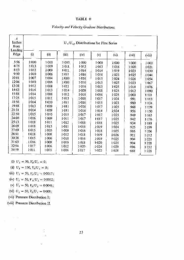
TABLE II
Velocity and Velocity Gradient Distributions.
X
Inches from
Leading Edge
5-56 6.75 8.13 9.50
10.81 12.06 13-38 14.63 15.88 17.25 18.56 19.88 21-31 22.50 24.00 25.13 26.69 27.69 28.81 30.38 31.63 32.94 34.19
(i)
1.000 1.013 1.012 1.010 1.007 1-010 1.012 1.016 1.014 1.015 1.014 1.013 1.014 1.015 1.016 1-018 1.018 1.015 1.018 1.015 1.016 1.017 1.011
U1/Uref Distributions for First Series
(ii)
1.000 1.009 1.009 1.006 1.004 1 "006 1.008 1"013 1-008 1.011 1.010 1 '009 1.009 1.010 1.009 1.011 1.013 1.005 1.008 1-006 1.009 1.006 1.003
(iii)
1.000 1"011 1.011 1.011 1.010 1.010 1.011 1"014 1.012 1.013 1.011 1.011 1.011 1.011 1.011 1.012 1.011 1.009 1.012 1.010 1.010 1.012 1 "006
(iv) (v)
1.000 1.013 1.014 1.016 1"016 1.016 1-016 1 "020 1.018 1.018 1.016 1.016 1-016 1.017 1.017 1.018 1.016 1.016 1.018 1.016 1.018 1.020 1.017
1 "000 1.013 1.014 1-016
! 1.015 I 1.015
1.015 1.018 1.016 1-017 1.015 1.017 1.014 1.017 1.017 1.018 1.019 1.018 1.019 1.019 1.020 1-024 1.022
(vi)
1.000 1-016 1.019 1 "023 1"024 1.025 1.025 1.025 1-025 1 "024 1.023 1 '025 1;024 1.025 1.025 1.025 1 '024 1.025 1.026 1.025 1-025 1.029 1.028
(vii)
1 "000 1 '020 1"023 1"025 1"026 1"023 1"018 1"012 1 "000 "991 "980 "968 "956 "949 "942 "934 "925 -916 "911
! .904 .904 '896
I .888 I
(viii)
1.000 1.021 1-030 1.044 1.054 1.067 1.076 1.090 1-101 1"113 1.124 1.139 1.150 1.163 1.176 1"188 1.199 1.206 1.212 1.221 1-228 1.232 1.228
(i) U1
(ii) U1
(iii) U1
(iv) U1
(v) U~
= 50, Vo/U~ = O;
= 150, Vo/U~ = O;
= 50, Vo/U I = 0.0017;
= 50, Vo/U 1 = 0.0032;
= 50, Vo/U ~ = 0.0046;
(vi) U1 = 50, Vo/U 1 = 0 ' 0 0 8 ;
(vii) Pressure Distribution I;
(viii) Pressure Distribution II.
23

TABLE II--continued
Velocity and Velocity Gradient Distributions.
X
Inches from
Leading Edge
5'43 6'73 8'13 9"58
11"04 11'95 13'37 14"69 16'01 17"35 18"65 19"45 20"41 21"25 21 "93 22"53 23"23 24'08 24'73 25 "43 25'88 26'78 27"43 28"23 28"63 29"58 30"18 31"03 31"43 32"53 33"28 34'13
Ul/Uref Distributions for Second Series
(i)
1"000 1-007 1"013 1-013 1"011 1'012 1'013 1'014 1'014 1.014 1'013 1"011 1'011 1'011 1"010 1"010 1"011 1"011 1"013 1"013 1"013 1"013 1'013 1'011 1'011 1'012 1"011 1'011 1"014 1.011 1"007 1 "007
(ii)
1 "000 1"011 1"021 1-025 1-026 1-028 1-029 1"030 1"032 1-034 1"035 1'034 1'032 1'032 1.031 1"031 1'030 1'031 1"032 1"032 1"032 1"031 1"032 1"032 1"033 1"033 1'032 1"032 1'032 1"034 1'034 1'035
(iii)
1.000 1.005 1.011 1.013 1.013 1.016 1.029 1.045 1.063 1.091 1.120 1.137 1.149 1.196 1.213 1.238 1.266 1.306 1"343 1"375 1.401 1.452 1"489 1"529 1.564 1.637 1-674 1.732 1.764 1.818 1.827 1.839
(iv)
1-000 1.009 1.016 1.015 1.014 1.016 1.019 1.022 1.024 1.030 1.022 1.02O 1.017 1.017 1.017 1.017 1.018 1.019 1-020 1.019 1.018 1.019 1.018 1 '016 1.015 1.018 1.014 1.015 1.017 1-017 1.007 1.004
( i) U , = 150, VolU, = 0 - 0 0 3 2 ;
(ii) U1 = 150, Vo/U1 = 0.008;
(iii) Pressure Distribution III;
(iv) Discontinuity in V o.
24

TABLE II--concluded
Velocity and Velocity Gradient Distributions.
X
Inches from
Leading Edge
10 11 12 13 14 15 16 17 18 19 20 21 22 23 24 25 26 27 28 29 3O 31 32 33 34
Smoothed Distributions of d(U1/Uref)/dx
(i) (ii) (iii) (iv) (v)
0 0 0 0 0 0 0 0 0 0 0 0
+.0004 +.0004 +.0004 +.0004 +.0004 +'0004 +.0004 +.OOO4 +.0004 +.0005 +.0O06 +.0007 +.00O8
0 --0015 --0036 -.O05O -.0060 -.0069 -.0076 -.0082 -.0086 -.0089 -.0086 -.0076 -.0066 -.0058 -.0055 --0059 -.0062 -.0063 -.0059 -.0053 -.0044 -.0035 -.0029 -.0026 -.0023
+.0104 +.0101 +'0097 +.0093 +.0090 +.0088 +.0086 +'0087 +.O089 +.0O92 +-0096 +.0O99 +.0101 +.0101 +.0098 +.0091 +.OO82 +.0068 +.006O +.0056 +.0055 +-O055 +.0O55 -'0005 -.0037
+'0025 +.0042 +.0063 +.0090 +.0123 +-0153 +.0182 +.0210 +'0240 +'0265 +.0297 +'0333 +.0373 +.0418 +.0467 +.0515 +.0560 +.0602 +.0647 +-0700 +-0730 +.0710 +.0440 +.0220 +.0065
+.0003 +.0007 +-0011 +.0016 +.0021 +'001.8 +'0010
0 -'OQ16 -.0025 -.0020 -.0012 -.0002 +.0011 +.0014 +-O005 --0006 -.0010 -.0013 -.0015 -.0016
- .0018 -.0019 -.0020 -.0020
(i) U 1 = 50, Vo/U i = 0'0046 (Nominally zero pressure gradient);
(ii) Pressure Distribution I ;
(iii) Pressure Distribution II;
(iv) Pressure Distribution III;
(v) Discontinuity in Vo (Nominally zero pressure gradient).
Note: Velocity gradients are per inch.
25
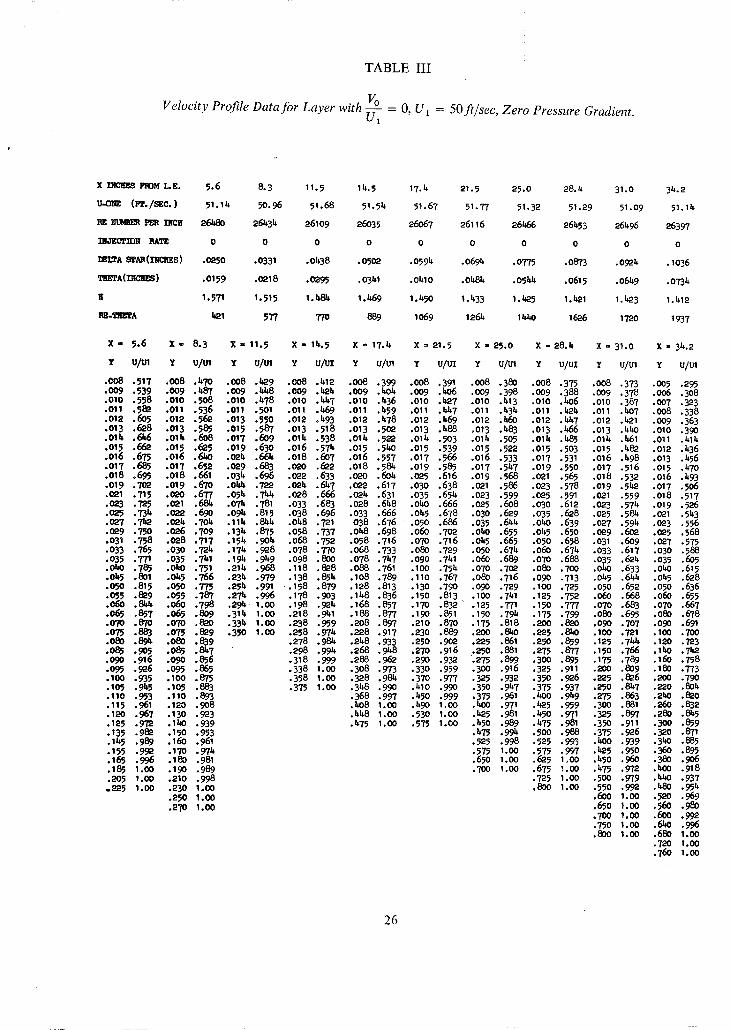
TABLE III
Vo Velocity Profile Data for Layer with ~ = O, U ~ = 50 ft/sec, Zero Pressure Gradient.
X Lv,:tu~ FROH LE, 5,6 8,3 11.5 14.5 17.4 21.5 25.0 28.4 31.O 35.2
U,,OH~ (PT./SEC. ) 51. l i t 9O.96 51.68 51.5lt 51.67 51.77 51.32 51.29 51.09 51.14
RE ~ PER IHCH 26580 261t34 26109 26035 26067 26116 26466 26~53 26496 26397
~qOEL~'rr~H RATE 0 0 0 0 0 0 0 0 0 0
IELTA ~AR (INCliES) ,029O ,0331 ,0438 ,0502 ,0595 .0694 ,0775 ,0873 ,0924 ,1036
T~ETA(~C]¢ES ) .0159 .0218 .0295 .0341 .o41o .Old~ .051dr .0615 .0649 .0734
K 1.571 1.515 1.48b, 1.469 1.450 1.433 1. b,25 1.521 1.523 1.512
RE-TllEt'A 521 577 770 8~9 1069 1265 1 b,40 1626 1720 1937
X .. p . 6 X = 8 . 3 X = 1 1 . 5 X - lb, .5 X - 1 7 . 4 X = 2 1 . 5 X = 2 5 . 0 X = 28.b.. X = 3 1 . 0 X = 34 .2
z u/~. z u / t . x u/m z u/uz Y u/u1 Y u/uz Y u/u1 Y u/uz y U/Ul ~ u/u,
,0o8 ,517 ,008 ,470 ,008 ,529 ,008 ,412 ,008 ,399 ,008 ,391 ,008 ,380 ,0o8 ,37? ,o08 .373 .o05 ,295 ,009 ,539 ,009 ,I~87 ,009 ,I~8 ,009 ,525 ,009 ,504 ,009 ,~o6 .009 ,398 ,009 ,388 ,009 ,378 .006 ,308 .010 .558 •010 .508 .010 .It78 .010 .1~,7 .010 .b,36 .010 .b,27 .010 .413 .010 .~O6 .010 .387 .007 .323 .011 .582 .O11 .536 •011 .~OI .011 .469 .011 .459 .011 .1t47 .011 .434 .011 .l~.h .011 .~O7 .008 .338 .012 .605 .O12 .562 .013 .550 •012 .b,93 .O12 .478 •012 .469 .012 .l~0 •012 .Ida7 .012 .521 .009 .363 .013 .628 .013 .585 .015 .587 .013 .518 .013 .502 .013 .488 .013 .483 .013 .L.56 .013 .550 .010 .39O .01b,..C9~6 .014 .608 .017 .609 .014 .538 .01 b, .522 .01b, .9O3 .015 .505 .011r . lrSp .o14 .561 .011 .b,15 .015 .662 .015 .6~5 .019 .630 .016 .57~. .015 .5~0 .015 .539 .015 .522 .015 .5O3 .015 .58~' .012 .436 .o16 .675 .o16 .69~o .o24 .66~ .o18 .607 .o16 .557 .o17 .566 .o16 .533 .o17 .531 .o16 .It98 .o13 .456 ,017 ,685 ,017 ,652 ,029 ,683 ,020 ,6~2 ,018 ,584 ,019 .585 ,017 ,51t7 ,019 ,550 ,017 .516 .015 .570 ,018 ,695 ,018 ,661 ,034 ,696 ,022 ,633 ,020 ,604 ;025 ,616 ,019 .568 ,021 ,565 .018 ,532 ,016 ,493 ,019 ,702 ,019 ,670 ,Ot~ ,722 .02~ .657 ,O22 ,617 ,030 ,638 ,021 ,586 ,023 ,578 ,019 ,552 ,017 ,506 ,021 ,715 ,~°0 ,677 .054 ,TL~ ,028 ,666 ,024 ,631 .035 ,654 ,023 ,599 ,025 ,591 ,021 .559 .018 .517 • {~3 ,T25 ,021 ,68~ ,074 ,781 ,033 ,683 ,028 .648 .0~0 .666 ,025 ,608 ,030 .612 ,023 .575 .019 .526 ,025 ,735. ,022 ,690 ,094 ,815 .038 ,696 ,033 ,666 ,045 ,678 .030 ,629 ,035 .628 .025 ,584 ,021 .55.3 • 027 ,752 ,024 ,704 ,114 ,Sit5 .048 ,7"21 038 ,676 ,050 ,686 ,035 .644 .050 ,639 ,027 .595 ,023 .556 • 029 ,750 ,026 ,709 ,134 ,875 ,058 .737 ,0~8 ,698 ,060 ,702 ,0~O ,655 .055 ,650 ,029 ,6O~ ,025 ,568 ,031 ,758 ,028 ,717 ,154 ,904 ,068 ,752 ,058 ,716 ,O70 ,716 ,O45 ,665 ,050 ,658 .031 ,609 ,027 ,575 ,033 ,765 ,030 ,724 .17~ .928 ,078 ,770 ,068 ,733 ,080 ,729 ,050 ,67~ ,06O ,674 ,033 .617 ,030 .588 • 035 ,771 ,035 ,7~1 ,19~ ,949 .098 ,800 ,078 ,7~7 ,090 .7~I ,06O .689 .070 .688 .035 ,624 ,035 ,6O5 .050 .78~ ,olto ,751 .214 .9~8 ,118 ,828 ,088 ,761 ,100 .754 ,070 ,7o2 ,082 ,700 .o~o .633 .0~0 .615 .055 .801 ,0~5 ,766 ,234 ,979 ,138 ,854 ,108 ,789 ,110 ,767 ,080 ,716 ,090 .713 .045 ,644 ,045 .628 .0~0 .815 .O50 .77~ .254 .991 .158 .879 .128 .813 .130 .7~O .090 .729 .100 .725 .O50 .652 .050 .636 .0~5 .829 .O55 .787 .274 .996 .178 .903 .148 .836 .150 .813 .100 .741 .125 .752 .060 .668 .060 .655 .~6o ,8~ ,060 ,798 ,29~ 1.00 ,198 .924 ,168 ,857 ,170 .832 ,125 ,T71 ,19O ,777 .070 .683 .070 ,667 • 0~5 .8~7 .06~ .809 .314 1.00 .218 .941 .188 .877 .lCjO .851 .150 .795 .175 .799 .080 .695 .080 .678 .070 .870 .O70 .820 .33 b, 1.00 .238 .959 .208 .897 .210 •870 .175 .818 .2OO .82O .O9O .707 .O9O .691 .075 .883 .075 .829 .350 1.00 .258 .974 .228 .917 .230 .889 .200 . ~ 0 .225 .8~O .100 .721 .100 .700 • 080 . 8 ~ .O80 .839 .085 .9O5 .085 .8~7 .090 .916 .O9O .856 .09~ .926 .O95 .865 .100 .935 . lOO .875 .1Op .9~,5 .105 .883 .11o ,953 .11o .893 .115 ,961 ,i~0 ,9O8 .120 .967 .130 .923 .125 .972 .1~0 .939 ,135 ,982 ,15o ,953 ,145 ,989 ,160 ,961 .155 .992 .170 .974 .165 .996 .180 .981 .185 1.o0 .19O .989 • 205 1.00 .~.IO .998 .225 1 . 0 0 .230 1.00
. 2 5 0 1.oo
.2"1'0 1 . 0 0
.278 •98~ •2b,8 •933 .250 .9O2 .P-2P •861 .250 .859 .125 .75~k .120 .723
.298 .99 b, .268 .9b,8 .270 .916 .250 .881 .275 .877 .150 .766 .1~O .742 • 318 ,999 ,288 ,962 ,29O .932 •275 •899 •300 .895 ,175 ,789 .16O ,758 • 338 1,00 ,308 ,973 ,330 ,959 ,300 ,916 ,325 ,911 ,200 ,809 .180 ,773 • 358 1.00 •328 ,985 ,370 ,977 ,325 •932 •350 ,926 •225 ,826 ,200 .79O • 375 1,00 ,348 ,990 ,410 ,990 ,350 ,957 ,375 ,937 ,250 ,8~7 ,220 ,804
,368 ,997 ,450 ,999 ,375 •961 •bOO ,9~9 .275 ,863 .2~0 •820 ,~08 1.00 ,490 1.00 ,500 ,971 ,525 ,959 ,300 ,881 .260 ,832 ,458 1.00 ,530 1,00 ,525 ,981 ,450 .971 ,325 ,897 ,280 ,8~5 ,475 1,00 ,575 1,00 ,450 ,989 ,~75 ,981 ,39O ,911 .3O0 ,859
• 475 •995 •500 ,988 .375 ,926 •320 .871 • 525 ,998 ,525 ,995 ,Z~O .939 ,3~0 ,885 • 575 1,00 ,575 ,997 ,525 ,950 ,360 ,895 ,650 1,00 ,625 I~00 ,~50 ,96O .380 ,9O6 • 700 1,00 ,675 '..00 ,475 ,972 ,500 .918
• 725 1,00 .500 ,979 ,5~0 ,937 ,800 1.00 ,550 ,992 ,~80 ,955
,600 1,00 .520 ,969 .65o I .OO .56o .980 .700 1.oo .6oo .gc/a ,750 1,00 ,6~0 ,996 ,800 1,oo ,68o i,o0
,720 1 ,o0 ,760 1,00
26

T A B L E III--continued
Vo = 0,0017, Ut = 50 fi/sec, Zero Pressure Gradient. Velocity Profile Data for Layer with - ~
X INCHES FE)H L.E. 5.6 8;3 11.5 14. 5 17.4 21.5 25.0 28.h 31.0 34.2
U-ONE (I~./SEC. ) 50.92 51.22 51.O5 51.O6 51.14 51.31 51.31 51.25 50.99 50.99
RE NU~I~ PER INCH 26261 26301 26295 269400 2628~ 26095 26095 26182 2642~ 26~e~.
INJECT1DB RATE .0017~ .00171 .00171 .00171 .00171 .00171 .00171 .00171 . 0 0 1 7 2 .00172
DELTA STAR(INCHES) .0260 .0388 .0565 .0679 .0832 .0968 .115,7 .1273 .1370 .15,70
THETA(INCRES) .0170 .0258 .0373 .05,55 .0555 .0655 .0770 .0859 .0929 .0999
R I. 526 I. 506 I. 516 1. b,93 1.5()0 I. 476 I. 4~ I. 482 I. 5,75 I. 471
~-~A Z~5,7 678 980 1201 15,58 1710 2010 2248 2454 26~
x = 5•6 x - 8.3 x = 11•5 x - 15,•5 x = 17.4 x = 21.5 x = 2%o x : 28.h x = 31.0 x = 3b,.2
Y u/u1 Y u/u1 Y u/u1 Y u/uz Y u/u1 Y u/uz ~ u/u1 Y u/u1 Y u/u1 Y vim
.005 .431 .005 .37o .OO5 .319 .OO5 .303 .OO5 .290 .oo5 .2?5 .005 .266 .OO5 .264 .oo5 .269 .005 .257 • 006 .455 •006 .~01 .006 .334 .006 .314 .006 .297 .006 .284 .006 .278 .006 .277 .006 .278 .006 .266 .007 .I~84 .007 [email protected] .007 .355, .007 .338 .007 .314 .007 .311, .007 .29"2 .007 .292 .007 .297 .007 .283 .008 .512 .008 .450 .008 .375 .008 .366 .008 .332 .008 .3b.~ .008 .311 .008 .311 .008 .313 .008 .303 .009 .533 .009 .473 .009 .396 .009 .391 .009 .355, .009 .367 .009 .325 .009 .326 .009 .329 .0O9 .322 .010 .558 .010 .496 .010 .419 •010 .415 .010 .372 .010 .391 .010 .3h4 .010 .351 .010 .31~ .010 .35,2 • 011 .578 .O11 .517 .011 .M~9. •011 .5,39 .011 .391 .011 .412 .011 .364 .011 .369 .011 .36k .011 .360 • 012 .595 .012 .537 •012 .461 .012 .461 .012 .h08 .012 .431 .012 .381 .012 .385 .012 .381 .012 .377 • 013 .610 .013 .551 .013 .481 .013 .476 .013 .@8 .013 .5,51 .013 .397 .013 .hO3 .013 .396 .013 .392 • 014 .@5 .014 .56k .014 .495 .014 .491 .015, .~49 .015, .463 .01b, .5,13 .015 [email protected] .014...k08 .01b, .h08 • o15 .635, .o15 .578 •015 .51o .015 .5o5, .015 .461 .o15 .474 .o15 [email protected] .o17 .45o .o15 .420 .o15 [email protected] .017 .653 .O17 :~19~5 •016 .521 .016 .517 .016 .474 .017 .5,95 .017 .5,49 .019 .469 •o17 .5,5,3 .017 .~I .019 .670 .019 .017 .532 .017 .527 .017 .484 .019 •511 .019 .~68 .o21 .~98. .019 .463 .019 .z~0 .021 .683 .021 .627 .019 .551 .019 . 5 @ . .019 .504 .021 .525, .021 .483 .025 .502 .0~i •478 . 0 2 1 .5,73 • 023 .695 .023 .636 .021 .566 .021 •556 .0~1 .521 .0"23 .532 -023 .5,95 .030 •522 .023 .h86 .023 .~90 .028 .718 .025 .646 -023 .577 .023 .566 -023 ,532 .025 .55,1 .025 .510 .035 .539 .025 .497 .025 .5,97 -033 .740 .030 .667 .025 .589 .025 .576 .025 .55,3 .030 .562 .030 .529 .OhO .55,9 .030 .520 .030 .513 .038 .758 .035 .685 .030 .608 .030 •595 .030 .565 .035 •576 .035 .55,6 .050 .571 .035 •535 .035 .530 .043 .777 .OhO •699 .035 •628 .035 .608 .035 .58e .OhO .587 .OhO .562 .060 .587 .OhO .55,7 .040 .5~ .048 .793 .045 .715 .OhO .642 .OhO .6~4 .OhO .596 .045 .598 .045 .572 .070 .603 .055 .558 .oi,5 .551 • 053 .808 .050 .728 .045 ,654 .045 .636 .045 .608 .050 .608 .050 .582 .080 .616 .050 .568 .050 .563 .058 .825 .055 .739 .050 ,666 .050 .65,5 .050 .618 .055 .616 .060 .600 .090 .629 .055 .576 .060 .575 .063 .8~I .060 .753 .055 .676 .060 .666 .055 .627 .060 .623 .070 .616 .100 .642 .060 .584 .070 .590 .068 .854 .07O .778 .060 .688 .07o •685, .060 .637 .07O .639 .080 .630 .120 .661 .07O .598 .080 .606 .O73 .868 .O8O .802 .065 .697 .08O .701 . 0 7 O .655, •08O .654 .090 .645 .1~0 .682 .O8O .613 .O9O .617 .078 .88Z .090 .822 .O7O .7O9 .090 .717 •O8O .669 .09O .667 .100 .655 .160 .703 .09O .625 . l O O .628 .083 .895 •100 .8~5 .OEO •729 •100 •733 .090 .684 .100 .681 .110 .666 .180 .722 .100 .636 .120 .6~6 .088 .908 .110 .86b, .09<) .7k6 .110 .750 .I00 .698 .110 .693 .120 .677 .20O .742 .110 .6~6 .IkO .667 .093 .919 .120 •889. .100 .76~ .120 .766 .110 .711 .120 .705, .IbO .7O0 .220 .757 .120 .658 .160 .685, .098 .927 .130 .~01 .110 .783 .13o •780 .120 .727 .IkO .727 .160 .722 .2~0 .773 .15,0 .673 .180 .701 .103 .936 j.140 .916 .120 .800 .IkO .794 .130 .7@. .160 .752 .180 .75,1 .260 .788 .160 .690 .200 .716 .108 .9~ b, •150 .932 •130 .818 .150 •808 .lkO .755 .180 .769 .200 .759 .280 .8o5, .180 .7O9 .220 .732 .113 .954 .160 .947 •1180 .835 .160 .8~2 .150 .767 .200 .792 .220 .777 .300 .818 .200 .726 .240 .75,5 .118 .962 •170 .961 .150 .851 .170 .835 .160 •781 .220 .811 .2;40 .794 .320 .831 .22o .7~ .260 .761 .128 .975 .180 .971 .160 .865 .180 .847 .170 .7B9 .2~0 .829 .260 .810 .340 .8~7 .2~0 .757 .280 .77b .138 .986 .190 .979 .170 .880 .190 .858 .180 .802 .260 .847 .280 .825 .360 .861 .260 .772 .30o .788 • 148 .991 .200 •986 • IBO .895 •200 .87O .190 .813 .280 .865 .300 .84-2 .380 •875 .280 .786 .320 .800 .158 •995 ,210 •996 •190 .906 •210 .881 .200 .825 .300 .882 .320 .858 •bOO •887 .300 .801 .340 .815, .168 .998 .230 .998 .200 .919 .220 .893 .210 .835 .320 .899 .340 .872 .420 .897 .320 .816 .360 .826 .178 1.00 .250 1.00 .210 .931 .230 ,~04 .220 .8~7 .340 .913 .360 .887 .440 .912 .340 .827 .380 .838 • 188 1.00 •270 1.00 .220 .945 .2~ .915 .230 .857 .360 .928 .380 .901 .460 .924 .360 .8@. .LK}O .849 .198 1.00 .290 1 .00 .230 .955 .250 .925 .2kO .867 .38O .940 .z<)O .913 .~80 .934 .380 .855, .LeO .859 .200 1.00 .3O0 1.00 .2ko .963 .26O .935 .250 .877 .~0o .954 .~--~ .928 .50O .�b,h J~:)O .867 .44O .875,
.250 .971 •270 .91~6 .260 .887 .k20 .965, .5,kO .939 .540 .963 .I.20 .881 .46O .885
.260 .979 .280 ;955 .270 .896 .L~,,O .972 .k60 .95,9 .58O .975 .5,~0 .891 .5,80 .896
.280 .989 .290 .960 .28O .906 .460 .980 .480 .959 .620 .989 .460 .902 .500 .906
.300 .995 .300 .968 .290 .916 .l~O .988 .5OO .968 .66O .99b. .b80 .91~, .52O .912 • 320 .999 .320 .980 .300 .923 .500 .991 .520 .976 .700 .999 .500 .924 .SbO .922 .3ko 1.00 .3~0 .989 .310 .931 .5~0 .999 .5~0 .983 .740 1.00 .520 .935 .560 .933 .360 1.00 .360 •994 .320 .939 .580 1.00 .56O .989 .78O 1 .00 .540 .95,5, .580 .943 .380 1.00 .380 .998 .3140 .955 .620 1.00 .600 .996 .8,?0 1 .00 .560 .953 .600 .950 .~00 1.00 .400 1.00 .360 .966 .660 1 .00 .640 1 .00 .900 1 .00 .580 .960 .620 .958
.LLoO 1.00 .380 .977 .700 1 .00 .680 1.00 .600 .968 .660 .970 • h~O I.(30 . ~ . 985 .720 1. CO .640 . 982 .7OO . 98~ .450 1.00 [email protected] .993 .800 1.co .680 .989 .TaO .992
.440 . 997 • 720 • 995 .780 . 996
.k60 1.00 .76O .999 .82O 1.00
.480 I . OO .800 1.00 .860 1.00 • 500 1.00 .840 1.00 .900 1.00
.9000 1.00
27

TABLE III--continued
leo Velocity Profile Data for Layer with ~ = 0.0032, U1 = 50 ft/sec, Zero Pressure Gradient.
X INCH~S FROM L.E. 5.6 8.3 11.5 12. 5 17.£ 21.5 25.0 28.2 31.0 34.2
U-ONE (Ft./SEC. ) £9.83 50.64 51.30 51.49 51.33 51.17 51.12 51.22 51.09 51.06
RE NIJ~ER PER INCH 25878 26347 26217 26317 26312 26389 264£7 26£98 26462 26368
INJECTION RATE .00335 .00330 .00326 • 0032£ .00325 .00326 • OO327 .00326 .00327 . OO327
DELTA STAR (INCHES) .0302 .0£93 .0739 .0900 ' .I095 .1356 .1569 .1817 .1937 .2085
THETA (INCHES) •0191 .0309 .056£ .0576 .0695 .0860 .0992 .1155 .1236 .133£
H 1.583 1.595 1.592 1.563 1.576 1.577 1.581 1.572 1.567 1.56£
RE-THETA £9£ 81 £ 1217 1515 1829 2270 262£ 3061 3271 3516
X = 5.6 X = 8.3 X = 11.5 X = 14.5 X = 17.4 X = 21.5 X = 25.0 X = 28.4 X = 31.0 X = 34.2
Y U/Ul Y u/u1 Y u/m Y u/ul Y u/u1 Y uIui Y UlUl Y u/ul Y UlUl Y UlUl
.005 •361 .005 .300 .005 .265 .005 .270 .005 .2bo .005 .219 .005 .219 .OO5 .223 .005 .224 .005 .201
.006 .38/* •006 .306 .006 .271 .006 .283 .006 .248 .006 .226 .006 .222 .006 .238 .006 .238 .006 •220
.oo7 .411 .0o7 .323 .oo7 •283 .oo7 .303 .0o7 .265 •007 .2~o .0o7 .228 .007 .25o •oo7 .246 •oo7 .228
.008 .h38 .o08 .3~8 .oo8 .306 .oo8 .318 .oo8 .284 .008 .26o .o08 .246 .0o8 .265 .0o8 .282 .oo8 .243
.009 .465 .009 .371 .009 .326 .009 .337 .009 .302 .009 .278 •009 .263 .009 .284 .009 .274 .009 .260
.o10 .49"2 .01o .394 .OlO .346 .01o .359 .OlO .321 .01o .294 .OlO .281 .o10 .300 .OlO .291 .o10 .276
.011 .511 .o11 .£18 .o11 .367 .011 .377 .o11 .3£1 .Oli .310 .o11 .296 .o11 .313 .o11 .303 .012 .303
.012 .532 .012 .£35 .012 .386 .012 .391 .o12 .356 .012 .328 .012 .312 .012 .328 .o12 .315 .o14 .332
.013 .5146 .013 .451 .o13 .bo4 .013 .bo£ .o13 .368 .o13 .346 .013 .326 .013 .339 .o14 .3140 .o16 .356
.o14 .560 .014 .I.68 .01£ .£18 .014 .415 .oi£ .382 .oi£ .357 .oi£ .339 .014 .352 .016 .358 .o18 .373
.015 .575 .015 .483 .o15 .430 .015 .ha6 .o15 .39£ .o15 .369 .o16 .367 .016 .369 .018 .37£ .020 •387
.017 .594 .017 .508 .017 .452 .017 . ~ .017 .£I£ .017 .390 .018 .38£ .018 •383 •020 .390 .025 .£14
.019 .61£ .019 .531 .019 .470 .019 .b66 .019 .~-32 •019 .b08 .020 boo .020 .396 .025 .£15 .030 .£31
.021 .630 .0'21 .544 .021 .48~ .021 .479 .021 .£47 .021 .L,28 .025 b~9 .025 •519 .030 .£31 .035 .bJ~5 • 023 •6~3 .023 .557 .023 .500 .023 .489 .023 .h5£ .023 .£37 .030 £52 ,030 .hbo .035 .h~9 .Obo •459 • 025 .656 .025 .570 .025 .511 .025 .£99 .0"25 .b68 .025 .hh9 .035 b65 .035 .453 .0110 .h60 .050 .480 • o3o •682 .030 .593 .o30 .53o .o30 .517 .o3o .b87 .o3o .£72 .obo £80 .0£o .46b. .o5o •483 .o60 .~95 • 035 . 705 .035 . 616 .035 . 550 .035 . 53h .035 . 503 .035 . 482 .045 489 .045 . 47£ .060 . 5O0 .070 . 508 .OhO .728 .Obo .632 .Obo .566 .Obo .551 .Obo .519 .O4O .k98 .O5O 5OO .05O ,~8£ .07O .513 .08O .521 • 045 .750 .0£5 .650 .045 .582 .0£5 .562 .045 .532 .04-5 .507 .060 516 .060 .501 .080 .528 .090 .536 .050 .768 .050 .66£ .050 .595 .050 .575 .050 .5£5 .050 .518 .070 .532 .070 .519 .100 .553 .100 .546 • o55 .786 .o55 .678 .055 .6o7 .055 .584 .06o .56k .06o .537 .08o .550 .o8o .533 .12o .572 .12o .563 .O6O .8o3 .O6O .691 .06O .618 .O6O .595 .070 .58£ .070 .553 .O9O .56o .090 .5£5 . lbo .592 .1bo .582 .065 .8~I .065 .705 .065 .6~8 .070 .615 .O80 .600 .080 .568 .100 .57£ .I00 .556 .16O .6O8 .16O .599 .070 .838 .070 .719 •070 .6£2 .080 .632 .090 •616 .090 .582 .120 .598 .120 .577 .180 .624 .180 .616 .080 .869 .080 .746 .075 .650 .090 .647 .100 .631 .100 .596 .1bo .620 .lh0 .597 .200 .6£3 .200 .630 .090 .895 .090 .771 .080 .659 .1OO .663 .110 .6h6 .120 .621 .160 .6bo .160 •615 .220 .66o .2bo •661 .1OO .917 .100 .79"2 .090 •679 .110 .681 .120 .660 .140 .645 .180 .662 .180 .634 .2hO •67£ .280 .688 .110 .939 .110 •817 .100 .701 •120 .696 .130 .672 .160 .667 .200 .680 .200 .650 .260 .688 .320 .716 .12o •953 .120 .8"59 .110 .719 .130 .711 .IhO .685 .180 .688 .220 .698 .220 .668 .280 .702 .360 .741 .130 .968 •130 .862 .120 .735 .Ibo .725 .150 •697 .200 .709 .240 .716 .2hO .68£ .300 .716 .400 .769 .IhO .976 .IhO .882 .130 .753 .150 .739 .160 .709 .220 .729 .260 .735 .260 •701 .340 .7b.h .£hO .793 • 150 .985 .150 .901 .11,0 .770 .16O .753 .180 .735 .2h0 .753 .280 •751 .280 .715 .3@0 .772 .h80 .816 .160 .990 .160 •916 .150 .790 .170 .767 .200 .760 .260 .772 •300 .768 .300 .729 .420 .799 .520 .839 • 170 .994 .170 •933 .160 .805 .I@O .780 .220 .783 .280 .790 .320 .785 .320 .745 .h60 .825 .560 .859 .190 .997 .180 .91,8 •170 .821 .190 .79£ .2h0 .803 .300 .805 .340 .800 .340 •761 .500 •849 .600 .880 .210 .999 .190 .960 .180 .837 .200 .809 .260 .827, .320 .826 .360 .817 .360 .776 .5bo •873 .640 •898 • 230 1.00 .200 .970 .190 .85h .210 .822 .280 .8/46 .3bo .841 .380 .832 .380 .790 .580 .895 .680 .919 .250 1.00 .220 •987 .200 .867 .220 .833 .300 .867 .360 .857 .bOO .845 hO0' .80h .620 .916 .720 -937 .270 1.00 .2bo .991* .210 .882 .230 .846 .320 .885 .380 .876 ./,40 .875 .hhO .832 .660 .93£ .760 .951, .300 1.oo .26O .998 . ~ 0 .896 .24o .857 .3£o .905 .boo .892 .£80 .9o2 .48o .857 .7oo .953 .80o .967
.o8o 1.00 .230 .909 .26O .881 .360 .922 .4bO .921 .520 .929 .520 .883 .Tbo .968 .850 .981
.320 1.00 .24O .9"2O .28O .903 .380 .9ki .480 .947 .560 .953 .560 .905 .780 .979 .900 .991 • 3bo 1.00 .250 .932 .300 .9"26 .bOO .953 .520 .967 .600 .969 .600 .928 .800 .984 .950 .999 .360 1.00 .260 .943 .32O .9£2 .42O .966 .560 .983 .6bO .983 .6bo .9£7 .850 .99£ 1.00 1.00 .1400 1.00 .28O . 9 6 3 .31'0 .958 .4bo .976 .60O .992 .68O .99"2 .68O .965 .900 .997 1.05 1.00
• 300 .977 .360 .97 '2 .460 .983 .6£0 .997 .720 .999 .720 .978 .950 1.00 1.10 1.00 .320 .987 .380 .982 .£80 .990 .68O 1.00 .76O 1.00 .760 .986 1.00 1.00 • 340 .994 .boo .989 .500 .996 .720 1.00 .80O 1.00 .E~OO .993 1.05 1.00 .360 .996 .b20 .993 .520 .998 .760 1.00 .8bo 1.00 .850 .997 1.10 1.00 • boO 1.00 .£bo .997 .560 1.00 .800 1.00 .900 1.00 .900 1.00 • £hO I. O0 . I,.80 1. OO .600 1. OO • 950 I. O0 .£~0 1.00 .520 1.00 .6bo 1.00 1.00 1.00 .500 1.00 .56O 1.00 .700 1.oo
28

TABLE III--continued
Vo Velocity Profile Data for Layer with ~ = 0.0046, U1 = 50 ft/sec, Zero Pressure Gradient.
INCHES FI~3M L.E. 5.6 8.3 11.5 lb-.5 17.55 21.5 25.0 28.4 31.0 35.2
J-ONE (~JL/SEC.) 50.8h 51.79 51.ho 51.30 51.36 51.h6 51.36 51.ho 51.35 51.315
~ PER INCH 29778 26376 26567 26517 26501 26468 ~_6h18 26h73 26531 26771
INJEOI'II3N RATE .00h68 . oot~50 . oo1563 . oo46h . oo463 . ooh63 .0o1563 . oo463 . oo463 . OOh6h
DELTA STAB (INOHES) .0330 .0559 .0869 .1111 .1377 .1701 .1933 .2235 .2371 .2560
T~u~-z'A( INCI4ES ) .O203 .O339 .O523 .O670 .082k . I0215 .1172 .1348 .15549 .1572
H 1.631 1.6158 1.662 1.658 1.672 1.661 1.6h8 1.657 1.636 1.62~
I~E-%'n~£A 922 6'95 1389 1776 21 83 2711 3097 3570 3E'~,5 haO8
X = 5.6 X = 8.3 X = 11.5 M = Ih.5 X = 17. h X : 21.5 X = 25.0 X : 28.4 X = 31.0 X = 355.2
Y U/U1 Y U/U1 Y U/U1 Y U/UI Y U/U1 Y U/UI Y U/U1 Y U/UI Y U/U1 Y U/U1
.005 .330 .005 .265 .005 .233 .005 .215 .005 .191 .005 .172 .005 .175 .005 .172 .005 .183 .005 .166
.006 .348 .006 .290 .006 .21;3 .006 .225 .006 .198 .006 .175 .006 .183 .006 .180 .006 .188 .006 .172
.007 .370 .007 .310 .007 .255 .007 .21,0 .007 .212 .007 .191 .007 .196 .007 .191 .007 .200 .007 .185
.008 .391 .008 .3e8 .O08 .275 .O08 .259 .008 -223 .008 .2O3 .0O8 .208 .O08 .200 .OO8 .207 .OO8 .195
.OO9 .416 .OO9 .352 .O09 .288 .009 .277 .OO9 .2ho .O09 .221 .OO9 .223 .O09 .21h .009 .221 .O09 .211
.010 .khe .010 .369 .010 .306 .010 .294 .010 .259 .010 .237 .010 .2ho .010 .225 .010 .253 .010 .222
.011 .~:)0 ,011 .389 .012 .343 .O12 .323 .012 .290 .012 .262 .012 .268 .012 .255 .O12 .259 .012 .2h9
.012 .5,81 .O12 .hOb .014 .371 .014 .352 .O14 .312 .014 .292 .0115 .297 .0155 .278 .014 .283 .0155 .274
.013 .500 .013 .418 .016 .393 .016 .370 .016 .335 .016 .314 .016 .316 .016 .297 .016 .301 .016 .2915
.O11~ .518 .014 .1533 .O18 .Ig)9 .018 .388 .018 .351 .018 .33 b, .018 .333 .018 .318 .O18 .318 .018 .312
.O15 .531 .O15 .55157 .O20 .425 .020 .hoO .O20 .365 .O20 .352 .O20 .3156 .O2O .336 .020 .336 .O2O .325
.017 .555 .o17 .h68 .025 .1553 .025 .h27 .025 .393 .025 .381 .o25 .373 .025 .357 .o25 .358 .o25 .35 I~
.019 .576 .019 .k85 .03o .I+81 .o30 .1550 .o3o .I,13 .030 .ho3 .o3o .39h .o3o .376 .o30 .379 .o3o .375
.0"21 .59"2 .021 .500 .035 .1599 .035 .h65 .035 .153o .035 .h2o .035 .5510 .035 .391 .035 .395 .035 .390
.o23 .608 .o23 .513 .oho .513 .oho .48o .oho .15155 .oho .43 b, .oho .h26 .oho .hOb, .ohO .hO9 .Oho .ho2
.O25 .623 .0~5 .525 .O45 .530 .O1~ 5 .15~2 .Oh5 .1559 .045 .~8 .O555 .1539 .O555 .t~16 .Ot~5 .1519 .0555 .55155
.030 .652 .030 .5159 .050 .Sb, t .050 .503 .050 .471 .050 .b,58 .050 .1550 .050 .1525 .050 .430 .050 .55a5
.035 .676 .035 .569 .060 .566 ,060 .525 .060 .495 .060 .1578 .060 .h68 .060 .1~l~ .060 .1550 .060 .h b,5
.OhO .699 .Oho .587 .070 .590 .070 .5h7 .070 .516 .070 .b,91* .07O .558a .o7o .1559 .o7o .h62 .o7o .~,56
.01*5 .'/'dO .0155 .6015 .080 .610 .080 .568 .080 .536 .080 .506 .080 .1595 .080 .1573 .080 .1577 .080 .1570
.090 .7h.2 .0.50 .619 .090 .630 .09O .587 .090 .552 .090 .520 .090 .909 .090 .1587 .090 .I,89 .090 .I,81
.06o .784 .06o .65o .IOO .651 . too .602 .11o .58o . I iO .5h6 .lOO .522 .IOO .1599 . loo .5oo .IOO .15915
.o8o .85b, .07o .68o .12o .688 .12o .636 .13o .609 .13o .571 .12o .945 .12o .517 .120 .519 .11o .5o5
.o9O .882 .080 .7o7 .lhO .729 .lhO .666 .15o ,635 .19o .593 .lhO .567 .14o .937 .lhO .539 .12o .515
.1oo .909 .090 .733 .160 .760 .16o .697 .200 .697 .200 .6158 .16o .583 .160 .557 .16o .556 .14o .532
.110 .931 .I00 .760 .180 -793 .180 .726 .290 .795 .250 .698 .180 .605 .180 .57"7 .180 .573 .160 .551
.120 .91,8 .120 .8O8 .200 .828 .2OO .793 .300 .812 .300 .7h6 .20O .622 .200 .596 .2OO .59O .180 .565
.11+0 .975 .1180 .851, .220:859 .220 .781 .350 .861 .350 .793 .250 .670 .250 .6315 .250 .625 .200 .585
.160 .989 .160 .893 .2ho .888 .2ho .807 .bOO .910 .hoO .836 .300 .708 .300 .673 .300 .6615 .250 .617
.180 .994 .180 .930 .260 .915 .260 .832 .450 .91'8 .1550 .878 .350 .752 .390 .713 .350 .698 .300 .61~9
.200 .998 .200 .959 .280 .�ho .280 .855 .500 .978 .900 .913 .hoO .791 .bOO .750 .hoO .733 .350 .681,
.2ho 1.00 .220 .980 .300 .961 .300 .880 .550 .993 .550 .9h2 .1550 .89.7 .kSO .781' .450 .766 .hoO .716
.280 1.00 .2ho .993 .320 .979 .320 .902 .600 .998 .600 .968 .500 .869 .500 .820 .500 .797 .450 .7155
.300 1.00 .26O .998 .3ho .988 .3ho .92t~ .650 1.00 .650 .985 .95O .898 .59O .892 .550 .826 .5OO .772 • 320 1.00 .280 1.00 .)80 .998 .360 .9hO .700 1.00 .700 .993 .600 .928 .600 .881 .600 .859 .950 .798 .35o 1.00 .3eo 1.00 .h2o 1.oo .380 .958 .750 1.0o .75o 1.oo .690 .954 .650 .911 .650 .883 .600 .897
.36o 1.oo .hfS 1.00 .400 .973 .80O 1.00 .8O0 1.0o .7OO .975 .700 .936 .7OO .9O8 .650 .852
.hoO 1.oo .9OO 1.00 .4ho .989 .Spo 1.oo .750 .987 .75O .955 .750 .932 .7OO .878 .h SO 1.oo .9O0 1.oo .8o0 .996 .800 .974 .8oo .953 .750 .903 .520 1.00 .850 1.00 .850 .987 .850 .969 .800 .925 .56o 1.oo .9O0 1.oo .9Oo .993 .9Oo .984 .85o .945 .600 I.OO .950 I.OO 1.00 .998 .950 .992 .9OO .961
I.OO 1.00 1.10 1.00 1.O0 .996 .950 .9755 1.20 1.O0 1.10 1.00 1.00 .991 1.30 1.00 1.20 1.00 1.10 .999
1.30 1.00 1.20 1.00 1.30 1.0o
29
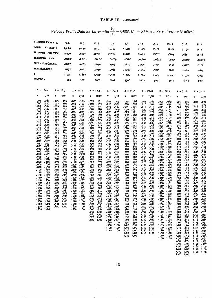
TABLE III--continued
Velocity Profile Data for Layer with ~ = 0.008, U 1 = 50 ft/sec, Zero Pressure Gradient.
x INCHES FROM L.E. 5.6 8.3 11.5 11..5 17.4 21.5 25.0 28. k 31.0 31..2
U-ORE (PI'./SEC.) 1.9.1~5 50.50 50.97 50.95 51.22 51.25 51.30 51.21. 51.32 51.57
RE ~ p ~ INCR 25530 261~67 26712 26781* 261.87 261~99 26807 26853 26651 267~8
II~JECTION RATE • OO833 .00816 .00808 .00809 . OO801. .00801. . OO803 .OOSOh .00803 .00799
DELTA STAR (Ills) .0~07 .0863 .11.70 .1925 .21,79 .3175 .3755 . I~h1.7 .k787 .510i
TltETA ( I~v~HES ) ,0237 ,01~1 ,0750 ,0986 ,121.9 ,1576 ,1873 ,2201 .21119 .2615
R 1.721 1.869 1.960 1.952 1.984 2.014 2.OO5 2.020 1.979 1.950
RE -THEI'A 60k 1221 2003 26~1 3308 1.I 77 5021 5911 6 l~li~ 6~5
X - 5.6 X - 8.3 X = 11.5 x - 11..5 X = 1%4 X = 21.5 x = 25.0 X = 28.b, x - 31.0 x - 31..2
Y u/in y u ~ l Y U/~l Y u/L~ y u/u1 Y u/ui Y u/m Y u/ui Y u/m Y u/u1
• oo5 .285 .0o5 .171. .oo5 .128 .oo5 .131 .0o5 .lO3 .oo5 .o88 .oo5 .o87 .005 .o82 .oo5 .o76 .0o5 .o75 .00~ .290 .00'7 .180 .010 .152 .010 .155 .010 .128 .010 .098 .010 .t02 .010 ,092 .007 .082 .010 .092 .007 .3Ok. .009 .205 .015 .206 .015 .201 .015 .167 .015 .121. .015 .119 .015 .115 .009 .093 .015 .111 .008 .3:~ .011 .238 .020 .250 .020 .2hO .020 .203 .020 .161 .020 .148 .020 .141 .011 .107 .020 .141 • OO9 .31'7 .013 .265 .025 .281. .025 .263 .025 .225 .025 .191 .025 .177 .025 .166 .013 .115 .025 .168 .010 .367 .015 .292 .030 .308 .030 .282 .030 .21~8 .030 .212 .030 .202 .030 .18~ .015 .138 .030 .189 .011 .382 .017 .316 .035 .327 .035 .300 .035 .261 .035 .225 .035 .218 .035 .197 .020 .157 .035 .211 .012 .t,~2 .019 .331 .oko .341 .0~0 .313 .0~0 .275 .oko .2L,,2 .040 .233 . 0 ~ .209 .025 .175 .0~0 .222 .o13 .lh?.l .o21 .347 .045 .353 .045 .325 .045 .285 .045 .255 .045 .2h8 .045 .220 .03o .193 .o45 .234 .or4 .436 .023 . 3 6 1 .O5O .368 .o50 .335 .050 .295 .O50 .263 .050 .258 .O5O .233 .035 .207 .050 .2h2 .o15 .1.h8 .025 .377 .055 .38O .o6o .353 .O6O .317 .O6O .282 .O6O .27"2 .06O .21.9 .oho .218 .06O .257 .017 .1.'~ .O27 .387 .O60 .394 .O7O .376 .07O .333 .O7O .298 .o7o .287 .07O .260 .050 .241 .o7o .275 .019 .b,93 .029 .396 .07O .h18 .080 .392 .080 .352 .080 ,311. .080 .304 .080 .271. .060 .258 .080 .288 .021 .509 . 0 3 1 . ~ 5 .08O .h38 .O9O .1.11 .O9O .368 .09O .328 .09O .311 .O9O .291 .07O .q69 .09O .298 .023 .527 .035 .1.22 .O90 .1.58 .100 .h26 .100 .38,?. .100 .3hO .100 .320 .100 .297 .080 .I.~79 .100 .309 .025 .539 .OhO . ~ .100 .b,77 .110 .1.38 .110 .39l' .110 .353 .120 .339 .120 .31k- .09O .,'-~93 .120 .327 .O3O .573 .Oh5 .Z,~ .110 .b,91. .120 .~,56 .120 .h06 .120 .365 .lhO .365 .lkO .333 .IO0 .3O6 .lkO .3~6 .035 .6O2 .05O .1.76 .120 .512 .130 .~7O .130 .1.19 .lhO .383 .160 . 3 8 1 .160 .352 .1tO .316 .160 .361 .OhO .626 .055 .1.9k .130 .530 .lhO .h86 .I~0 .1.35 .16O .h05 .180 .399 .180 .371 .120 .321. .I~0 .376 .01.5 .652 .060 .~t6 .140 .551 .150 .500 .150 ./~9 ,180 .lh21~ .200 .1.16 .SO0 .388 .lhO .341 .L~O .391 .09O .6'7~ .0~ .521. .150 .568 .160 .512 .16O .1.57 .2OO .1*tr5 .220 .b,33 .220 .h02 .16O .355 .220 .h03 .055 .703 .07O .540 .160 .586 .17O .528 .180 .1.81 .220 .1.62 .2hO .~.9 .2l, O .411 .180 .369 .2~O .1.12 .060 .721. .O80 .568 .17O .6O~, .180 .5k4 .200 .501 .21~0 .t~O .260 .t~? .26O .k27 .200 .387 .26O .th?t~ .070 .766 .O90 .591. .180 .621 .200 .573 .220 .523 .260 .1.97 .280 .1.77 .280 .h39 .220 .401 .280 .1.36 .080 .806 .I00 .622 .200 .656 .220 .596 .2t,3 .5k3 .280 .519 .300 .1.92 .300 .453 .2kO .ho9 .300 .hb,5 .o9o .838 .110 .69O .220 .693 .2ko .626 .26O .566 .3o0 .535 .320 .507 .320 .b/~6 .26O .k~o3 .32o .1.58 . ioo .868 .120 .677 .2ho ,729 .26O ,656 .280 .592 .320 .555 .31~0 .525 .3l~0 .b.80 .280 .k35 .3ko .h67 .110 .895 .130 .703 .26O .762 .280 .680 .300 .612 .3~0 .572 .360 .51.I .36O .1.96 .300 .h/t8 .360 .1.77 .120 .919 .1~O .729 .280 .796 .300 .706 .320 .635 .360 .589 .380 .557 .h00 .521. .320 .~59 .380 .h87 ,130 ,9~0 .16O ,778 ,300 ,826 ,320 .732 ,340 ,658 .380 .606 ,kO0 ,57O .kilo ,549 .31~0 .h.TO .bOO .1.97 ,lhO ,956 ,180 ,823 ,320 ,857 ,3~O ,758 ,360 ,678 .b~O ,627 ,;~leO ,597 ,k80 .578 ,36O ,~Sa ,h/00 .517 ,150 ,968 ,200 ,861. ,340 ,881. ,360 ,785 ,380 ,703 ,k20 .(9*7 .1~0 ,630 .520 ,601 .380 ,1.93 ,1~0 .539 .160 ,979 ,220 ,905 ,36@ ,913 ,380 .807 ,~00 ,721 ,k~O ,665 .520 .659 ,560 ,621. .I~OO ,505 ,520 .558 .170 .988 .2ko .939 .380 .933 .bOO .832 .4~0 .71.3 .1~0 .680 .560 .688 .600 .6h8 .1*hO .531 .56O .581 .180 .991. .26O .96~ .bOO .953 .h20 .8~5 .1*hO .765 .hSO .699 .6OO .717 .6hO .672 .hSO .553 .6Oo .6o2 .SO0 .99~ .280 .985 .b~O .973 .h40 .877 .h60 .78~ .500 .715 .640 .7~0 ~66O .7O2 .520 .577 .6ho .622 .220 .998 .320 .999 ,h1~ .986 .~0 .898 .hSO .803 .ShO .752 .680 .778 .720 .722 ,56O .~99 .680 .6~a .26O 1,oo ,36O 1,oo .kSo .996 ,~8o ,918 .Soo ,823 .58o ,78~ ,720 .80~. .760 .7~6 ,6o0 .626 ,720 ,661. .280 1.OO .~00 1.00 .520 1.00 .500 .939 .520 .Sb~ . ~ 0 .811. .76O .830 .800 .771 .640 .61.7 .76O .681. .3OO 1.00 . ~ 0 1.00 .56O 1.00 .520 .953 .56O .881 .66O .8~.5 .8OO .856 .85O .8O2 .68O .669 .8OO .7O3 • 320 1.00 .1.50 1.OO .6OO 1.00 .56O .98O .6OO .911. .7O0 .871 .85O .893 .900 .831 .720 .692 .850 .728 .35o 1.0o .7oo 100o .6Oo .994 .6hO .gb,~ .ThO .899 .900 .9~8 .950 .861 .760 .711. .~00 .755
.6hO 1.00 .680 .966 .780 .925 .9~0 .91.1 1.00 .889 .800 .737 .950 .780
.680 1.0o .720 .98k .800 .931. 1.o0 .960 1.05 .910 .850 .759 1.00 .807
.720 1.OO .76O .993 .850 .963 1.05 ,975 1.10 ,931 .9O0 ,788 1.05 .831
.820 1.00 .800 .997 .9o0 .980 1.10 .987 1.15 .951. .950 .818 1.1o .853 , ~ 0 1.00 ,~50 ,99~ 1,20 ,995 1,20 ,969 1,00 .81.3 1.15 ,877 ,9oo 1,oo 1,oo ,999 1,3o ,999 1.25 ,979 1,05 ,861~ 1,20 ,896 1.0O 1,oo 1,o5 1.oo 1,~o 1,oo 1,30 ,99O 1.1o ,887 1,25 ,915 1,10 1,0o 1.1o 1,oo 1,5o 1,oo 1oto ,997 1,15 .91o 1,30 ,936
1,20 1,OO 1,6o 1,0o 1.50 1,00 1,20 ,929 1,35 ,953 1,3o 1,00 1,6o 1,0o 1,25 ,952 1,~0 .963
1.70 1.00 1.30 .961. 1.50 .981 1.35 .976 1.60 .993 I,t~0 .98~ 1.70 .997 1.50 .996 1.80 I.O0 1.60 1.00 1.90 1.00 1.70 1.00 2.00 1.00 1.80 1.00
30
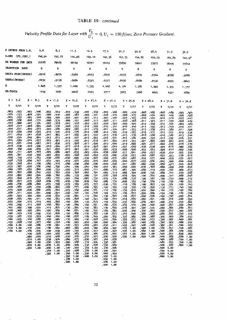
TABLE III--continued
Velocity Profile Data for Layer with ff~- = O, U1 = 150 ft/sec, Zero Pressure Gradient. w~
x II~RES FR3M L.E. 5.6 8.3 11.5 15.5 17.h 21.5 25.0 28.15 31.0 315.2
U-ONE (gl'./SEC. ) 11,6.015 1155.77 1155.28 Ih5. I0 1155.36 1155.75 11.1.. 87 141..59 11.1.. 89 Ih5.9 I~
RE NUM~ PER INCH 75186 751575 7611,,?. 76751 761h9 75890 76621 77277 76495 75812
INJECTION RATE 0 0 0 0 0 0 0 0 0 0
DELTA 8~AR ( INCH~S ) .0216 .02715 .0369 .0453 .0499 .0599 .0670 .074~ .0786 .0888
Trm'l'A( INCRgS ) .0152 .0196 .026~ .0325 .0357 .01530 .048~ .O530 .0565 .061.5
1.b~5 1.397 1.1500 1.393 I.h00 1.3915 1.385 I./g)15 1.395 1.377
RE-TKETA 11152 11581 2008 2493 2717 3263 3708 15095 1.321 15889
X = 5.6 X = 8. 3 X = 11.5 X = 14.5 X = 17.4 X = 21. 5 X = 25.0 X = 28.4 X = 31.0 X = 34.2
Y u/u1 y u/u1 Y u/m Y u/uz Y u/u1 Y u/uz Y u/u1 y u/uz Y u/u1 Y u/u1
.003 .523 .003 .496 .003 .449 .003 .432 .005 .48O .005 .466 .005 .459 .008 .ha2 .008 .480 .0O5 .~21.
.004 .533 .004 .521 .0015 .470 .004 .b67 .006 491 .006 .1.71. .006 .1.73 .009 .491. .009 .1.90 .006 .428
.OO5 .555 .O05 .548 .005 .504 .005 .491 .007 513 .007 .1.97 .OO7 .493 .010 .510 .010 .510 .O07 .1.1.? ,006 .582 .006 .571 .006 .531. .006 .521 .008 537 .008 .511 .008 .508 .011 .523 .Oll .530 .0O8 .1.72 .007 .600 ,0O7 .594 .0O7 .558 .007 .538 .0O9 557 .009 .529 .009 .529 .012 .5~0 .012 .51.5 .0o9 .489 .008 .617 .OO8 .6O5 .OO8 .576 .008 .553 .010 569 .010 .541 .010 .542 .013 .552 .013 .559 .010 .511 .OO9 ,631 .O09 .619 .OO9 .585 .OO9 .565 .011 579 .011 .554 .011 .553 .015 .5?O .014 .569 .011 .526 .010 ,640 .010 .~,9 .010 .595 .010 .575 .012 586 .012 .565 .012 .563 .016 .577 .015 .575 .0'12 .536 .011 .649 .011 .638 .011 .6o3 .011 .583 .013 597 .o13 .576 .013 .570 .018 .588 .016 .580 .013 .51.~ - .012 .654 .012 .6154 .013 .614 .012 .591 .011..603 .015 .591 .015 .581. .020 .597 .018 .592 .o14 .551 .014 .669 .0115 .657 .o15 .627 .013 .597 .015 .61o .017 .602 .o17 .593 .021 .6O5 .020 .603 .016 .564 .016 .681 .016 .667 .017 .636 .015 .6o8 .017 .6?o .019 .610 .o19 .602 .025 .617 .o22 .610 .018 ;575 .018 .692 .018 .680 .019 .6~.4 .017 .618 .019 .628 .021 .619 .021 .610 .030 .630 .024 .616 .020 .582 .020 .7o2 .o20 .689 .021 .655 .019 .6.?7 .021 .636 .o25 .632 .o26 .626 .035 .6153 .o26 .621 .022 .590 .022 .711 .025 .707 .023 .661, .021 .632 .023 .644 .030 .648 .031 .641 .0140 .657 .030 .632 .025 .599 .02~ .721 .030 .726 .025 .672 .025 .648 .o25 .649 .035 .662 .036 .653 .045 .667 .035 .643 .030 .612 .026 .730 .035 .743 .030 .687 .030 .665 .o3o .667 .oho .674 .041 .66? .050 .677 .o40 .656 .035 .627 .028 .738 .0180 .757 .035 .703 .035 .677 .035 .679 .045 .683 .01.6 .677 .055 .681. .01.5 .664 .oho .640 .o30 .71.8 .045 .770 .oho .716 .oho .69"2 .oho .690 .050 .696 .051 .685 .o6o .69"2 .050 .673 .o45 .648 • 035 .767 .050 .786 .045 .730 .045 .7o5 .045 .702 .055 .703 .056 .695 .070 .708 .060 .69o .050 .656 .01.0 .787 .055 .8o0 .050 .739 .050 .715 .050 .711 .06O .710 .061 .70~ .o80 .719 .070 .?oh .060 .673 .0h,5 .8o7 .060 .812 .055 .752 .055 .728 .055 .721 .065 .719 .066 .709 .09o .73 b, .080 .715 .o70 .688 .050 .8O2 .065 .8O15 .060 .762 .060 .739 .060 .731 .070 .728 .076 .724 .100 .74,5 .09O .727 .08o .698 .o55 .840 .070 .837 .065 .775 .o65 .746 .065 .739 .o75 .734 .o86 .738 .120 .767 . lOO .739 .o9O .712 .O6O .857 .075 .8~8 .070 .785 .07o ,756 .O7O .71.9 .o8o .739 .o96 .752 .lh0 .789 .110 .75o .10o .723 .o65 .872 .080 .860 .075 .796 .075 .765 .075 .757 .090 .755 .116 .776 .160 .8o7 .12o . 7 6 1 .12o .743 .070 .887 .085 .870 .080 .8o6 .080 .777 .o80 .765 . lOO .769 .136 .798 .18o .826 .13o .773 .I~O .762 .075 .900 .090 . 8 ~ .085 .816 .085 .782 .090 .781 .11o .782 .156 .816 .200 .846 .lho .779 .16o .780 .O8O .911 .099 .891 .O9O .827 .O9O .791 , l O O .798 .12o .793 .176 .837 .22O .86o .15o .79o .18o .796 .085 .923 . l O O .900 .095 . ~ 5 .09~ .801 .110 .810 .130 .PO7 .196 .857 .240 .876 .16O .798 .~90 .811. .09O .934 .I05 .911 .I00 .8153 .I00 .808 .120 .8O3 .lhO .819 .216 .875 .260 .891 .180 .816 .220 .830 .095 .9155 .110 .919 .105 .852 .110 .8O15 .13o .839 .150 .832 .236 .89"2 .280 .907 .200 .832 .21.0 .84~ .100 .952 .115 .926 .110 .862 .120 .840 . 140 .851 . 16o .839 .256 .910 .3OO .920 .220 .847 .26O .858 .105 .96O .120 .934 .115 .871 .130 .851. .150 .863 .170 .850 .276 .92? .32O .934 .2~0 .86~ .28O .873 .110 .965 .125 , 9 ~ .120 .880 . lho .871 .160 .875 .180 .863 .296 .940 .3h0 .947 .260 .8?7 .300 .885 .120 .979 .130 "~2 . 130 . ~ . II ~ 0 .88O .170 .88? .190 .873 .316 .950 .360 .958 .280 .895 .340 .912 .130 .987 .135 .959 .lh0 .910 .160 .897 .180 .899 .20o .882 .336 .962 .38o .968 .3OO .9o9 .38o .933 . lh0 .993 . lh0 ,965 .150 .9215 .170 ,909 ,190 .908 .210 .894 .356 .973 .40o .977 ,320 .9~2 .420 .9515 .150 .998 .150 .977 .160 .938 .180 .922 .2oo .92o .220 .9o4 .396 .989 .15~0 .989 .3~0 .929 .h6o .9?2 .160 1.00 .160 .986 .170 .9~1 .190 ,933 .210 .929 .230 .911 .1536 .997 .48o .998 .36o .9151 .50o -979 .170 1.0o .17o .992 .180 .962 .2oo . 9 ~ .220 .940 .2b0 .922 .1576 1.00 .520 1.oo .38o .953 .5~0 .987 .180 1.00 .180 .995 .190 .972 .21o .995 .230 .91.7 .250 .929 .1.96 1.0o .56o 1.oo .boo .964 .58o .9915
.190 .998 .2oo .986 .22o .963 .250 .961. .270 .9155 .516 1.0o .6oo 1.00 .42o .973 .62o .998
.20o .999 .210 .986 .23o ,97o .270 .97? .29o .956 .55o 1.00 .65o 1.00 .h~o .982 .66o 1.00
.210 1.00 .230 .994 .240 .977 ,29O .987 .310 .970
.220 1.00 .250 .999 .260 .988 .310 .994 .330 .981
.230 1 .00 .270 1 .00 .280 .9915 .330 .998 .350 .989 • 250 1.oo .29o 1.0o .30o .997 .350 1.00 .3?o .99~
.310 1,0O .32o .998 .370 1.o0 .39O .997 • 325 1.00 .3~O 1.00 .390 I.OO .~I0 .999
.360 1.0o .bOO 1.0o .153o 1.oo
.380 1.00 .450 1.00
.400 1.00 .470 1.00 .500 1.00
.z~O .986 .7OO 1.00
.480 .993 .7z~ 1.00
.500 .997 .8OO 1.00
.520 loO0
.5~) 1.0o ,56o 1.oo .600 1.oo
31

TABLE III---continued
Velocity Profile Data for Layer with ~ - = 0.0032, U~ = 150 ft/sec, Zero Pressure Gradient.
X INCHES FROM I.E. 5.6 8.5 11.5 I~.5 17.4 21.5 25.0 28.~ 31.0 3~.2
O-ON~ (PT./SEC. ) 1~.59 11~8.1~9 1;48.13 149 .34 148 .89 11~8.13 1~1/3.3~r 147 .99 1158.57 147.64
RE ] ~ PER It~t~H 71~79 75572 75651 752~ 75573 75753 75238 75620 75785 75903
INu'ECTION RATE .00321 . 00317 .00317 .00315 . 00316 . 00317 . 00317 . 0 0 3 1 8 , o 0 3 1 6 .00318
DELTA STRR ( INCHES ) .0251 .0386 .0599 .0783 .0958 .I~30 .1383 .1636 .1777 .1972
TH~TA(I~HES) .0164 .0251 .0380 .0494 .06O5 .077~ .0878 .I030 .1129 .1258
H 1.536 1.540 1.579 1.584 1.585 1,595 1.575 1.588 1.574 1.567
RE -~q~'TA I~18 1894 2872 3718 4569 58~ 6609 7791 8554 9552
X = 5 . 6 X = 8 . 5 X = 1 1 . 5 X = 1 4 . 5 X = 1 7 . 4 X = 2 1 . 5 X = 2 5 . 0 X = 2 8 . 4 X = 3 1 . 0 X = 3 4 . 2
x U/Ul x UlUl x uIu1 x uIu1 Y ulu1 r uluI Y ulu1 x ulul Y uIu1 x ulul
.o05 .470 .005 .~o6 .0o5 .341 .005 .327 .00p .296 .005 .27~ .005 .268 .005 .258 .005 .253 .o05 .261
.o06 .~83 .0o6 .~3 .006 .35~ .oo6 .332 .o06 .314 .006 ,283 .006 .27& ,o06 .260 .oo6 .263 .006 .270 • o07 .5o6 .0o7 .~ .oo7 .372 .007 .343 .o07 .329 .o07 .29~ .007 .285 .oo7 .269 .007 .276 .oo7 ,277 .0o8 .52) .oo8 -~7 .oo8 .390 .oo8 -357 .008 .3t~ .008 .316 .008 .300 .oo8 .28a .0o8 .291 .008 .288 .009 .545 .0o9 ,~87 .o09 .409 .009 .369 .009 .36o .0o9 .334 .009 .316 .0o9 .299 .009 .307 .o09 .3o2 .010 .5~ .OlO .504 .OlO .he7 .01o .382 .olo .3?6 .o10 .3~9 .01o .334 .o~o .315 .OlO .322 .OlO .313 .o11 .578 ,o11 .518 .o11 .~ .o11 .399 .011 .390 .o11 .36o .o11 .351 .o11 .328 .o11 .335 .o11 .326 .o12 .59o .o12 .529 .012 .h53 .o12 .412 .o12 .boo .o12 ,371 .o12 .365 .o12 .3k3 .012 .3~ ,o12 .337 .o13 .6o~ .o13 .539 .o13 .46o .o13 .he5 .o13 .~o8 .o13 .381 .o13 .375 .o13 .354 .o13 .357 .o13 .347 .O14 .612 .014 .549 .01Z~ .~70 .Oih .436 .O14 .417 .014 .390 .014 .38h .014 .364 .014 .365 .O14 .355 .015 .621 .015 .957 .O15 .k?8 .O15 .hZ~6 .O15 .he4 .015 .39? .015 .39e .O15 .370 .015 -372 .015 .363 .016 .629 .016 .563 .017 .~92 .016 .~.55 .017 .437 .017 .412 .017 .4O5 .017 .382 .O17 .386 .017 .376 .017 .637 .017 .569 .019 .903 .O18 .h6~ .019 .451 .019 .~3 .O19 .417 .019 .392 .019 .396 .019 .387 .018 .644 .O19 .58~ .O21 -513 .O20 .~78 .021 .460 .021 .433 .O21 .he6 .021 .h04 .021 .hO6 .021 .395 .019 .651 .021 .593 .023 .523 .O22 .487 .023 .k68 .O23 .4hO .023 .434 .023 .412 .023 .414 .O23 .403 .021 .665 .023 .6O4 .O25 .534 .024 .~97 .O25 .475 .O25 .E48 .O25 .4~3 .025 .1~18 .025 .he2 .025 .410 .023 .677 .025 .614 .027 -5he .026 .506 .030 .492 .030 .h6~ .O30 .462 .030 .437 .O3O -~38 .O3O .Ze5 • 025 .689 .O3O .636 .O~9 .551 .028 .514 .035 .508 -039 .~80 .035 .476 .O35 .~50 .035 .~51 .O35 .438 .o30 .717 ,o35 .655 .o31 .958 .o30 .520 .oho .523 .ObO .~94 .040 .~89 .OhO .463 •ObO .463 .o4o .~5o • o35 .741 .oho .673 .o33 .565 .o35 .537 .ok5 .536 .o~5 .506 .o45 .5o2 .0~5 .~73 .045 .~75 .o45 .~99 .obo ,76~. .o5o ,7o8 ,o3~ ,572 .o~o .552 ,o50 ,5~.7 ,O5O ,516 ,050 .514 .05o ,48~ ,050 .L~85 .05o .~7O ,09O ,8O6 ,060 .740 ,o~0 ,587 .o~-5 .565 ,o55 .558 ,055 ,525 .o55 .523 .055 ,~95 ,o55 ,L~94 .055 ,~79 ,O6O ,8~.4 ,O7O ,77O ,O45 ,6O2 ,O50 ,577 .O60 .569 .O6O ,53~ ,O6O ,533 .060 ,5O4 .O6O ,5O2 ,06O .488 .07O .876 .080 .798 .09O .617 .055 .589 .065 .579 .065 .5~3 .O65 .5~I .070 .521 .070 .518 .070 .50~ .O80 .9O2 .090 .8e5 .O6O ;6~5 .O6O .599 .O70 .588 .O70 .551 .O70 .550 .08O .535 .08O .532 .080 .519 .O~ .9"25 .tO0 .851 .080 .695 .065 .6O9 .079 .598 .08O .567 .080 .565 .O90 .549 .09O .5~5 .090 .934 .100 .91~ .11o .87~ .100 .The .070 •619 .100 .6he .O9o .58~ .090 .580 .100 .563 .100 .558 .I00 .545 .110 .96O .120 .894 .120 .785 .0'75 •631 .125 .68e .100 .597 .IO0 .593 .150 .617 .150 .609 .150 .597 .ISO .972 .130 .912 .I~O .826 .100 .6~e .15o .72~ .120 .~5 .12o .615 .200 .667 .20o .654 .2oo .638 .130 .98~ .ib0 .930 .160 .86~ .125 .728 .175 .799 .160 .677 .16O .66O .29O .713 .~50 .69~ .29O .679 .I~0 .99o .15o .951 .180 .899 ~19O .770 .20o . ~ .so0 .726 .200 .699 •300 .756 .300 .73~ .300 .714 .160 .99~ .16o .963 .2oo .9~7 .175 .810 .225 . .2~o .772 .2ho .741 .350 .796 .350 .772 .35o .7~8 .180 1 .o0 •170 .975 .220 .953 .2oo .8~8 .250 .8~8 .28o .815 .28o .78o .boo .836 .~00 .8o9 .~0o .783 .so0 1.00 .180 .985 .240 .971 .225 .883 .275 .886 .320 .8~6 .320 .817 .~50 .873 .450 .8~5 .~50 .811~ .22o 1.oo .20o .993 .260 .987 .250 .918 .300 •913 .360 .895 .36o .851 .500 .906 .500 ,878 .500 .8~
.~20 .999 .280 .�ge .279 .947 .325 .937 .400 •93o .4oo .88~ •550 .938 .55o .9o9 .550 .87~
.2~0 1.00 .300 .997 .30o •969 .350 .958 .M~O .958 .z~o .915 .600 .965 .600 .937 .600 .9OI~
.260 1.00 .3~o 1.00 .3~5 .98~ .375 .973 .480 .978 .480 .9~5 .650 .98o .650 .960 .650 .930
.280 1.00 .380 1.0o .350 .993 .400 .98~ .520 .990 .520 .968 .70o .993 .700 .978 .700 .951 . I ~ 1.00 .375 .999 .1~5 .994 .96o .999 .560 .98~ .750 .997 .750 .988 .750 .966
.~0o 1 .00 .450 .997 .600 1 .00 .600 .991 .800 1.00 .800 .995 .80o .979
.~50 1 .00 .500 1 .00 .6~0 1.00 .640 •998 .900 1.0o .890 .998 .850 .988 • 500 1.00 ,59O 1.00 .700 1.00 .680 1 .00 I.o0 I.o0 .9o0 1 .00 .9OO .99~
.600 1.00 .?SO 1.00 1.00 1 .00 1 .00 .999 .800 1.00 1.10 1.00 1 .10 1.00
1 ,SO 1.00 1.30 1.00
32

TABLE III--continued
Velocity Profile Data for Layer wi~h ~ = 0.008, U~ = 150 ft/sec, Zero Pressure Gradient. u 1
X INCHES FROM L.E. 5.6 8.3 11.5 I~.5 17.4 21.5 25.0 28.;4 31.0 3~.2
U-0~E (1PI',/SEC, ) 1]~., 83 146.O2 11~6, 95 147.39 1 4 8 . O 4 1~,50 lb.8, O2 147.78 1/~S, 13 I b,7, 47
RE NU~BF~ PER INCH 7~017 75435 75684 76280 760~8 75817 76268 75980 75699 76654
INJECTION RATE .O0812 .0079~ .00787 .00788 • 00785 .00783 • 00787 .00786 .00784 .00783
DELTA STAR (INCHES) .0299 .0625 .1161 .1583 .2138 .2811 .3258 .3843 .~180 .~
THETA(INCHES) .0184 .0353 .0594 .0817 .1048 .1393 .1661 .1931 .2165 .2385
H 1,627 1,769 1,953 1.937 2,O~O 2.018 1.961 1.990 1.931 1.863
RE -ri"a~l]~rA 1362 2666 k J,99 6234 7973 10560 12669 I b.673 16387 18280
X - 5.6 X = 8.3 X = 11.5 X = 14.5 X = 17.4 X = 21.5 Z = 25.0 X = 28.4 X = 31.0 X = 3~.2
Y ulm y u/u1 Y U/Ul y u/,rz y u/u1 Y u/uz y u/u1 y u/uz y v im Y u/u,
.005 .390 .0o5 .258 .005 .159 .0o5 .1~'.5 .005 .o86 .0o5 .104 .005 .106 .005 .069 .0o5 .o88 .oo5 .1o4
.006 .397 .006 .269 .006 .161 .006 .154 .006 .o9o .006 .107 .oo6 .109 .0o6 .o74 .006 .o92 .006 .1~ ~
.0o7 .t~13 .007 .283 .007 .165 .007 .165 .007 .09b .007 .110 .007 .113 .o07 .078 .007 .097 .oo7 .11. ~
.008 .~32 .008 .301 .0o8 .171 .008 .177 .008 .o97 .008 .116 .008 .119 .008 .o84. .008 .lO2 .008 .12o
.oo9 .k51 .009 .316 .010 .19~ .010 .200 .oo9 .101~ .009 .122 .009 .127 .009 .o9o .010 .116 .OlO .135
.010 .471 .o10 .331 .012 .220 .012 .218 .o io .113 .010 .130 .010 .135 .01o .096 .015 .152 .015 .168 ,Oll ,1~88 ,Ol l ,3k5 ,014 ,241 ,01k ,236 ,O12 .130 .012 ,1]~ ,O12 .149 ,012 .110 ,020 ,174 .020 ,192 ,O12 ,503 ,012 ,357 ,016 ,258 ,016 .250 .014 " I ~ .O1E ,158 .014 ,164 ,014 .125 .030 ,213 ,030 ,226 ,O13 ,515 ,O13 ,367 ,018 ,272 ,018 ,262 ,016 , ,O16 ,170 ,016 .174 .O16 ,138 .040 .238 ,O~O .254 .01h .528 .014 .3T,' .020 .283 .020 .271 .018 .178 .018 .180 .018 .18~ .018 .145 .050 .257 .050 .275 .015 .511.I .015 .38~ .025 .309 .025 .291 .020 .187 .020 .191 .020 .193 .020 .152 .060 .275 .060 .291 .017 ,560 ,O17 ,1~0 ,O30 ,333 ,O30 ,308 ,O25 ,213 ,O25 ,214 ,025 .213 ,030 ,188 ,070 ,289 ,080 ,320 • 019 .578 .019 .~14 .035 .350 .035 .3211- .030 .232 .030 .229 .030 .228 .040 .218 .080 .305 .100 .34J~ .021 .596 .021 .I..26 .0~0 .367 .0~O .338 .035 .2k8 .035 .244 .035 .2b-2 .050 .238 .100 .329 .120 .365 • O23 .611 .023 .438 .Ok5 .38~ .O~P .351 .0~O .263 .0~0 .256 .040 .255 .060 .257 .120 .351 .I~0 .385 .025 .625 .025 .k49 .050 .397 .050 .361 .O~5 .278 .OpO .277 .050 .275 .070 .275 .I~0 .369 .160 .40~ • 030 .658 .030 .471 .055 .~10 .060 .383 .050 .292 .060 .296 .060 .294 .080 .292 .160 .386 .180 .417 • 035 .687 .035 .~93 .O60 .~3 .070 .402 .060 .316 .070 .313 .O70 .31~ .090 .306 .180 .~03 .200 .431 .0~O .716 .0140 .515 .065 .k38 .080 .1425 .070 .338 .080 .326 .080 .329 .100 .321 .200 .E19 .250 .L~4 • 0~5 .7~ .0~5 .534 .070 .451 .090 .l~t~ .080 .358 .090 .3140 .090 .3~3 .120 .345 .220 .433 .300 .~92 .050 .766 .050 .552 .075 .~63 .100 .~60 .090 .375 .100 .352 .100 .354 .I~0 .368 .2~O .~7 .350 .519 '~55 .789 .055 .570 .080 .~77 .120 .496 .100 .391 .120 .378 .120 .376 .160 .388 .260 .461 .~00 .5~7 ~O .809 .060 .589 .090 .503 .I~O .530 .120 .1421 .1~O .~00 .1~0 .397 .180 .~OP .280 .~7~ .450 .574
.... 35 .8e9 .07o .628 .100 .528 .16o . 5 ~ . 1 ~ .~50 .160 . ~ 3 .160 .419 .200 .~1 .300 .z~6 .50o .60~
.070 .846 .080 .661 .11o .554 .18o .59~ .16o J~81 .180 .ht~4 .1~0 .t~36 .~oo .h.38 .35o .519 .55o .630
.o80 .877 .o9o .691 .120 .575 .200 .627 .18o .5o8 .2oo .~63 .~0 .454 .2~O .455 .~00 .550 .600 .656
.090 .90~ .100 .722 .I~O .620 .220 .661 .200 .537 .920 .48k .25o .49h .260 .47o .kSo .581 .650 .679
.100 .929 .110 .75k .16o .667 .2~o .694 .2~o .59~ .2~o .506 .300 .532 .280 .484 .500 .613 .700 .705
.110 .947 .120 .782 .18o .71o .260 .?27 .280 .6~5 .260 ,526 .350 .574 .300 .499 .55o .6L~ .750 .730
.120 .963 .13o .811 .200 .752 .280 .758 .320 .698 .280 .5~7 .~oo .614 .350 .533 .600 .675 .800 .755
.ly) .975 .I~O .837 .920 .792 .300 .787 .360 .7E8 .300 .568 .I.5o .653 .~.30 .568 .650 .704 .900 .805
.1'~o .985 .15o .863 .2~o .831 .320 .819 .~oo .79k .350 .620 .50o .694 .450 .6oi .700 .733 1.0o .856
.15o .993 .16o .888 .260 .867 .3~o .847 .~o .814o .~oo .672 .550 .737 .500 .638 .750 .763 1.1o .899
.160 .996 .17o .9o9 .280 .901 .360 .879 .hSO .883 .h~O .721 .60o .775 .550 .67h .800 .792 1.2o .935
.180 1.0o .18o .928 .300 .932 .380 .9oi .520 .92~ .500 .767 .650 .813 .600 .709 .850 .822 1.3o .966
.200 1.00 .1~0 .9k5 .320 .958 .bOO .925 .560 .958 .550 .813 .700 .852 .650 .7h2 .~00 .8h9 1.t=O .986
.220 1.00 .200 .960 .3~O .975 .t~o .9~6 .600 .980 .600 .859 .750 .888 .700 .77k .950 .874 1.50 .995 • 250 1.00 .210 .97~ .360 .989 .t~O .96~ .6~O .991 .650 .901 .800 .921 .750 .806 1.00 .897 1.60 1.00
• 220 .985 .380 .997 .~60 .977 .680 .999 .700 .937 .850 .9~7 .eO0 .836 1.05 .919 1.70 1.00 .2~O .995 .~0 1.00 .500 .991 .720 1.00 .750 .966 .900 .970 .850 .870 1.10 .9~1 1.80 1.00 .260 .999 .t~O 1.00 .5~0 .998 .760 1.00 .800 .98~ .950 .98~ .900 .900 1.20 .971 .280 1.00 .500 ~.00 .580 1.00 .800 1.00 .850 .993 1.00 .9y2 .950 .927 1.30 .990 ,320 1.00 .620 ~1.00 ,900 .997 1.10 .99~ 1.00 .91~9 1.kO .997 .1~00 1.00 .700 1.00 1.00 1.00 1.20 1.00 1.05 .968 1.50 1,00
1.10 1.00 1.30 1.00 1.10 .979 1.60 1.00 1.20 1.00 I.~0 1.00 1.20 .99~ 1.70 1.00
1.30 1.00 1JlO 1.00
33

TABLE III--continued
Velocity Profile Data for Layer with Pressure Distribution I.
X INCHES FROM L.E. 5.6 8.3 11.5 14. 5 17.4 21.5 25.0 28.4 31.0 34.2
U-ONE (FT./SEC.) 53.68 54.97 54.71 54.36 53.07 51.35 50.10 48.88 h8.41 47,57
RE ~ ~ INCH 28325 29097 29086 28897 27871 26964 26517 25857 255~6 25400
INJECTION RATE .001~ .00178 .00179 .00180 .00184 ,001~0 .00195 ,00200 .O0~Y2 ,00~05
DELTA STAR(INCHES) .0271 .0~02 .0565 .0758 .0968 .1291 .1531 .1832 .2023 .2225
THETA (INCHES) .0174 .0262 .0373 .0498 .0620 .0817 .0976 .115~ .128~ .I~04
H 1.560 1.533 1.516 1.522 1.562 1.579 1.569 1.587 1.575 1.584
RE -TH~fA 492 763 1084 I ~40 1727 2204 2588 2981, 3287 3567
X = 5.6 X - 8. 3 X = 11. 5 X = 14.5 X = 17.4 X = 21. 5 X = 25.0 X = 28.4 X = 31,0 X = 34.2
Y u/u1 r u/u1 r u/u1 y u/uz y u/ut Y u/ur ~ u/u1 Y u/uz y u/u1 r u/u1
.o05 .398 .005 .351 .005 .320 .o05 .299 .005 •251 .oo5 •219 .0o5 .229 .0o5 .209 .005 .223 .005 .188 • 006 .413 .006 .368 .006 .338 •007 •334 .0o7 .282 •007 .249 •oo7 .255 .007 .236 .0o7 ,243 .o07 .207 • oo7 •z~? .oo7 ,394 .0o7 .365 .0o9 .375 .009 .326 .0o9 ,287 .oo9 .290 .009 .272 .0o9 .275 .009 .231 .008 .471 •008..4,0_2 .008 .391 .011 .415 .o11 .363 .o11 .325 .011 .332 .o11 ,304 .o11 .308 .o11 .259 • oo9 .5oi .009 .41~5 .oo9 .417 .o13 .b~47 .o13 .396 •013 .358 ,013 .365 .013 .334 •013 .331 .o13 .294 .010 .525 .o10 ,467 .o10 .440 .o15 .472 .o15 •42o .015 .385 .o15 .387 .015 .355 .015 .358 .015 .323 .011 .549 .011 .493 .o11 .k63 .017 .492 .o17 .439 .017 .408 .o17 -407 .017 .378 .017 ,375 .017 .34z~ .o12 •569 .012 •511 .012 .481 .019 .505 .019 .452 .019 .426 .019 ,h21 .o19 .39"2 .019 .390 .019 .367 .o13 -582 .o13 .527 .013 .492 .o21 .520 .021 .46~ .o21 .437 .o21 •h32 .021 .4o6 .021 .402 ,021 .382 .014 .595 .Olk .541 .o14 .506 .023 .530 .023 .474 .023 .t~k8 .023 .4kl~ .023 .417 .023 .414 .023 .396 .015 .609 .015 .553 .015 .522 .O25 .541 ,O25 .486 .025 .458 .025 .454 .025 .429 .025 .~24 .025 .404 .017 .630 .017 .573 .017 .538 .O3O .56O .O30 .5O4 .03O .48O .030 .k72 .030 .k~5 ,030 .~41 .030 .k24 • 019 .648 .019 .589 .019 .553 ,035 •577 .035 .523 .035 .495 .035 .h85 .035 ,461 .035 .458 .035 .440 .021 .662 .021 .606 .021 .566 ,ObO .589 .O40 .539 .040 .506 .O40 .~94 .040 .468 .040 .469 .OkO .452 .O23 .674 .023 .616 .O23 .575 ,045 ,6O2 .O45 .553 .050 .527 .05O .514 .050 .486 .050 .k86 .050 .47k .o25 .686 .O25 .627 .025 ,585 .O5O .612 .05O .563 .06o .5k3 .O6O ,528 .O6O .5o5 .O60 .5o2 .O6O .k88 • o30 .7o7 .030 .649 .o3o .6o3 .06o .633 .o6o .585 .070 .560 .o70 .51~2 .070 .517 .070 .516 .08o .5o9 • o35 .731 .035 .669 •035 .62o .o7o .65b .o7o .6o8 .08o .574 .08o .557 .o80 .527 .080 .523 .IO0 .531 .oko .754 .O40 .686 .O40 .634 .O8O .672 ,O8O .626 .IOO .6OO .too .578 .100 .552 .IOO .545 .120 .550 .o45 .774 .o45 .7oi .045 .650 .090 .690 .o90 .642 .12o .627 .12o .6oi .120 .571 .12o .963 .140 .568 ,050 .791 .o5o .717 .o50 .661 ,IOO .7o7 .100 .656 .140 .649 ,140 .621 .140 .590 .IL, O .579 .160 .584 • 055 .810 .055 .73O .055 .672 .110 .723 .12O .685 .16o ,672 .160 .643 .160 .6O7 .160 ,596 .180 .6OO .O6O .8O.6 .O6O . 7 ~ .O6O .68~, ,12o ,736 . 1 ~ .714 .18o .695 .180 .66o .180 .625 .18o .610 .2OO .613 .065 .8~2 .065 .757 .070 .7o5 .130 .751 .160 .741 .2OO .716 .2OO .679 .2O0 . 6 ~ .200 ,626 .240 . 6 ~ .O7O .858 .O7O .77o .O8O .?25 .140 .768 .180 .765 .22o .738 .22O .699 .240 .674 .22O ,641 .28O .669 .o8o .886 .O8O ,796 .O90 .744 .150 .785 .2OO .791 .240 •759 .240 .717 .28O .7O7 .240 .655 .32O .693 ~090 ,911 .o9o .817 . too .762 .16O .798 .220 .814 .260 .779 .26O .735 ,32O .737 .28o .685 .36O .722 .I0O ,933 •10o ,SZ~? .110 .782 .180 .8~ 7 .240 •837 .280 .8oi •280 .752 .36O .768 .320 .713 .400 .745 .11o .951 .110 ,862 .120 .799 ,2OO .85O .26O .859 .3OO .82O .3O0 .769 .kO0 .798 ,360 .742 .4L, O .771 .120 ,967 .12o .889. .140 .835 .22O .874 .28O .88O .32O .838 .320 .788 .t~O .828 .40O .769 .48O .796 .130 .977 .130 .902 .16O .865 .2~0 .899 .300 •899 .340 .854 .340 •804 .480 .856 .4~O •796 .520 .818 .140 .989 .140 .918 .180 .894 .260 .919 .320 .916 .360 .875 .360 .819 .520 .882 .480 .823 .560 .8~0 .16O .994 .150 .935 .200 .923 .280 ~937 .340 .935 .380 .890 .bOO .848 .56O .909 .520 .847 .6O0 .863 .180 .997 .160 .949 .22O .945 .300 .954 .360 ~954 .400 .909 .~O .880 .600 .931 .560 .872 .640 .886 .220 1.00 .170 .962 .240 .966 .32O .968 .boo .976 .420 .925 .480 .909 .6~0 .952 .600 .896 .680 .906 .260 1.00 .180 .973 .260 .981 .360 .988 .440 .992 .440 .937 .520 .938 .680 .968 .640 .917 .720 .928 .300 1.00 .2O0 .986 .280 .991 .~00 .996 .480 1.00 .480 .961 .560 .958 .720 .983 .680 .939 .760 .946
.220 .994 .320 •998 •440 1.00 .52O 1.00 •520 .980 .600 .976 .760 .990 .720 .955 .800 .960
.240 .998 .36O 1.00 .480 1.oo .550 1.00 .560 .993 .640 .990 .800 .997 .760 .968 .850 .977
.280 1.00 .400 1.00 .500 1.00 .600 .998 •680 .995 .850 1.00 .800 .980 .900 .987 • 320 1.00 .500 I.O0 .640 1.00 .720 .998 .900 1.00 .850 .992 1.00 .996 • 350 1.00 .680 1.00 .76O 1.00 1.00 1.00 .900 .997" 1.10 1.00
.7OO 1.00 .8Oo 1.00 1.00 I.OO I.;~0 1.00 .850 1.00 1.10 1.00 1.30 1.O0 .900 1.00 1.20 1.00
34

TABLE III--continued
Velocity Profile Data for Layer with Pressure Distribution II .
x INCHES FROM L,E, 5,6 8,3 11,5 14.5 17,4 21.5 25.0 28,4 31,0 34.2
U-ONE (FT,/SEC, ) 44,38 46,12 47,59 48.86 ~9,96 51-79 53, u~ 54,75 55. 44 55,h 1
RE NUMBER PER INCH 23463 24158 24857 25652 26151 26945 27~67 28099 2845k 28528
INJECTION RATE . OO850 .00826 .00815 .00804 .00797 .00786 .00775 .00769 .00767 .00763
DELTA STAR(INCHES) ,0408 ,0799 ,1273 ,1536 ,1770 ,2065 ,2208 ,2479 ,268~ ,3052
THETA(INC~S ) ,0229 ,0436 ,0691 ,0854 ,0994 ,1185 ,1287 ,1443 .1569 ,17hl
H 1,779 1,834 1,843 1,798 1,782 1,742 1,716 1,719 1,711 1,753
RE-THETA 538 1052 1716 2192 2598 3193 3535 bo53 4463 4968
X = 5,6 X = 8,3 X = 11,5 X = 14,5 X = 17,4 X = 21,5 X = 25,0 X = 28,.4 X = 31,0 X = 34,2
Y u/u1 Y u/m ~ ~Iu1 Y uIuz Y UlOl Y ~lu~ Y ulm Y ului Y ulu1 Y uIu1
,005 ,256 ,005 ,191 ,005 ,159 ,005 ,174 ,005 ,155 ,005 ,150 ,005 ,143 ,005 ,151 ,005 ,155 ,005 ,111 ,007 ,275 ,007 ,197 ,007 ,166 ,010 .188 ,010 ,173 ,010 ,167 ,O10 ,169 ,010 ,167 ,O10 .177 ,O10 ,14k ,009 ,307 ,009 ,219 ,009 ,179 ,015 ,242. ,015 ,232 .015 ,220 ,015 ,225 ,015 ,222 ,015 ,219 ,015 ,188 ,O11 ,353 ,011 ,249 ,011 ,191 ,017 ,265 ,017 ,251 ,017 ,245 ,017 ,2b~ ,020 ,260 ,020 ,262 ,020 .230 • 013 ,387 ,013 ,278 ,013 ,215 ,019 ,284 ,019 ,265 ,019 ,265 ,019 ,263 ,025 ,292 ,025 ,290 ,025 ,255 ,015 ,417 ,015 ,306 ,015 ,2b~ ,021 ,300 .021 ,279 ,021 ,280 ,021 ,279 ,030 ,315 ,030 ,311 ,030 ,276 • 017 .~3 .017 .328 .020 .295 .023 .313 .023 .292 .023 .293 .023 .293 .035 .330 .035 .329 .035 .299 .019 .465 .019 .349 .025 .330 .025 .323 .025 .305 .025 .307 .025 .3O7 .0bo .346 .0~0 .344 .040 .313 .021 .~79 .021 .366 .030 .355 .030 .348 .030 .329 .030 .335 .030 .329 .045 .358 .045 .358 .050 .336 .023 .502 .023 .381 .035 .374 .035 .366 .035 .348 .035 .354 .035 .349 .050 .370 .050 .369 .060 .358 .025 .522 .025 .392 .0bo .391 .040 .380 .040 .365 .040 .368 .0bo .365 .060 .389 .060 .390 .070 .377 ,027 .538 .030 .~a4 .045 .bo9 .045 .396 .045 .380 .045 .381 .045 .379 .070 .410 .07O .412 .080 .388 • 029 .552 .035 .~9 .050 .~3 .050 .411 .050 .393 .050 .393 .050 .388 .080 .ha9 .080 .~3 .090 .403 .031 .568 .eb, O .468 .060 .b/~ .055 .1~3 .055 .h05 .060 .416 .o6O .411 .050 .546 .09o .437 .10o .418 .033 .582 .045 .487 .070 .472 .060 .437 .060 .416 .070 .434 .o70 .~3o .lO"', .459 .100 .450 .12o .44~, • 035 .594 .050 .503 .o80 .496 .065 .449 ,070 .435 .080 .45o .o80 .449 .11o .471 .110 .I~62 .14o .466 .040 .620 .055 .523 .090 .518 .070 .459 .080 .454 .090 .466 .090 .~64 .120 .~86 .120 .474 .160 .486 .045 .651 .060 .535 .100 .536 .080 .477 .O90 .475 .100 .482 .100 .478 .I~0 .506 .lbO .497 .180 .50k ,050 ,675 ,065 ,551 ,110 ,556 ,090 ,493 ,I00 ,494 ,110 ,495 ,110 .492 ,160 ,528 ,16O ,515 .200 ,523 • 055 .70'2 .070 .565 .120 .576 .100 .508 .11o .5o8 .12o .506 .120 .5o4 .18o .550 .180 .537 .2bo .554 ,060 ,725 ,080 ,594 ,130 ,594 ,110 ,526 ,120 ,525 ,140 ,532 ,130 ,517 ,200 ,571 ,20o ,556 ,28o ,583 .065 .746 .090 .6~2 .140 .611 .120 .51~a .13o .541 .16o .555 .140 .53o .2bo .6(y2 .22o .572 .320 .612 .o70 .769 .I0O .651 .160 .646 .13o .557 .Ih0 .553 .180 .575 .16o .551 .28o .636 .24o .587 .360 .6bo .080 .810 .110 .674 .18o .679 .14o .574 .16o .579 .20o .595 .180 .572 .32o .668 .280 .616 .boo .667 .090 .84-~. .120 .703 .~X) .714 .160 .6oe .18o .6o4 .22o .615 .2oo .591 .36o .698 .320 .6k6 . ~ o .692 .100 .877 .130 .7'28 .22o .748 .18o .628 .2o0 .626 .2bo .635 .22o .61o .boo .729 .360 .677 .[,,8o .718 .11o .905 .II;0 .757 .2bo .779 .2oo .656 .220 .649 .260 .653 .24o .63o .L,~O .755 .boo .703 .52o .7ha .120 .931 .150 .781 .260 .809 .220 .683 .240 .673 .280 .672 .26O .647 .[~0 .781 .44q .731 .56O .766 • 130 .950 .160 .805 .280 .840 .240 .709 .260 .695 .320 .711 .280 .666 .520 .809 .480 •755 .600 .789 .140 .961 .170 .8a8 .300 .867 .260 .734 .280 .717 .360 .747 .320 .699 .560 .832 .520 .781 .650 .817 .160 .982 .180 .846 .320 .892 .280 .761 .300 .737 .hO0 .783 .360 .730 .600 .857 .560 .803 .700 .8~ .180 .994 .200 .890 .3bo .9"20 .300 .785 .320 .759 .h/~0 .815 .boo .759 .640 .878 .6OO .828 .750 .867 .200 .997 .220 .928 .360 .941 .320 .809 .360 .800 .480 .846 .4bo .788 .680 .900 .640 .848 .800 .891 .2umO 1.00 .2bo .958 .380 .962 .340 .834 .L~O0 .840 .520 .876 .480 .816 .720 .919 .680 .871 .850 .912 .24o 1.oo .26O .978 .~o0 .975 .36o .857 .44o .876 .96O . 901 .520 .845 .760 .938 .7~0 .891 .900 .934 .260 1.00 .280 .988 .4~0 .9°/2 .380 .878 .~80 .910 .600 .925 .560 .867 .800 .95b .760 .911 .950 .953 .300 1.00 .300 .995 .I,,80 .998 .boo .899 .520 .9bo .6bo .950 .600 .895 .850 .970 .800 .927 1.00 .966
.340 1.00 .52O 1.00 .440 .937 .560 .964 .68O .969 .6bo .919 .9OO .983 .850 .9~5 1.10 .989
.360 1.00 .560 1.00 .480 .968 .600 .982 .720 .980 .680 .9bo .950 .992 .900 .966 1.20 .996
.380 1.00 .600 1.00 .520 .986 .6~0 .992 .760 .988 .720 .956 1.00 .996 .950 .979 1.30 1.00 ,~20 1,OO ,560 ,9~6 ,680 ,997 ,800 ,995 ,76o ,971 1.10 1,00 1,00 ,988 I,~O 1,00 • 450 1,00 ,600 1,00 ,720 1,00 ,850 1,00 ,800 ,983 1,20 1,00 1,10 ,998 1,50 1,00
.6bo 1.00 .76o 1.00 .900 1.00 .850 .992 1.30 1 .0O 1.20 1.00
.680 1.00 .80O 1.00 .95O 1.00 .900 .998 1.30 1.00
.700 1.00 1.00 1.00 .950 1.00 1.40 1.00 1.00 1.00 1.05 1.00 I .I0 1.00
35
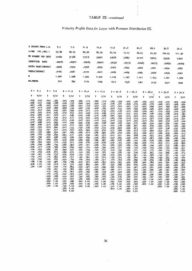
TABLE III--continued
Velocity Profile Data for Layer with Pressure Distribution I I I .
X INCHES F]~3M L.E. 5.3 7.9 11.2 II~,2 17.0 21.8 215.8 28.2 30.8 34.2
U-ONE (Fr./SEO.) 59.82 60.43 60.50 62.52 65.42 ?3.43 8~.O3 93.22 I04,03 111.9~2
~E NU~ PER INCH 31069 31386 31518 32227 33678 37867 151718 157615 53295 57091
INJECTION RATE .O~74 • 00~71 .00289 • O0291 .00321 .00372 .00663 .00573 .00655 • 00702
DELTA STAR ( INC"HES ) .0~52 .0399 ,0568 .067~ .0707 .0693 .0656 .0641 .0632 .0891
THETA(INCHES) .O165 .0261 .0372 .01547 .0480 .0485 .0~65 .0M~ 7 .0438 .0~61
H 1,5215 I . 526 I . 525 I . 502 I . 472 I . ~ 7 I . 411 I . 1533 I . ~ I I . 589
I~E-TBETA 51 15 ~ 0 11715 I b/~ 1617 1838 1941 2130 2337 3202
x - 5.3 x = V.9 x = 1 1 . 2 X= l~ . . ~ × = 1 7 . 0 x - 2 1 . 8 x = 2 4 . S x - 2 S . 2 x = 3 o . 8 x - 3 4 . 2
Y U/UI Y U/UI Y U/U1 Y U/121 Y U/UI Y U/~ Y U/UI Y U/UI'~" y U/U1 Y U/UI
• 005 .439 .O05 .364 .OO5 .322 .OO5 .3115 .OO5 .319 .OO5 .359 .OO5 .354 .005 .357 .O05 .3?3 .OO5 .256 • 0o6 .457 .o06 .388 .oo6 .338 .0o6 ,329 .oo6 .335 .oo6 .381 .o06 .374 .006 .378 .006 .383 .o06 .265 .0o7 ,485 .007 .416 .007 .366 .007 .348 .oo7 .357 .007 .bo? •007 .397 .0o7 .b02 .007 .402 .007 .282 • oo8 .518 .oo8 .4h6 .oo8 .39"2 .oo8 .372 .oo8 .383 .oo8 .433 .oo8 . ~ 5 .oo8 .b2_e .oo8 .~a3 .008 •305 .oo9 .547 .0o9 .472 .oo9 . ~ 0 .oi0 .417 •o10 .43o .OlO .472 .OlO .469 •01o .h61 .OlO .459 ,OlO .338 .o10 .569 .o i0 .1593 .OlO .~A3 .012 .458 .o12 ,466 .012 .5oo .012 .5o3 .012 .b88 .o12 .488 ,012 ,363 • o12 .6o2 .o11 .515 .011 .h60 .o14 .486 .o14 .498 .01h .522 .014 .529 .014 ,509 .0115 .5o8 .o14 .384 .o14 .6e7 .012 .530 .012 .h77 .o16 .5o9 .016 .517 .016 .5ho •016 .549 .016 •527 ,016 .524 .o16 .bOl .016 ,650 .o13 .545 ,013 .49o .018 .525 .o18 .533 .018 .555 .o18 .563 .o18 .541 ,018 .538 .o18 .41k .018 .668 .015 •569 ,o14 .502 .o2o .54o .o2o .5h8 .o2o .567 .02o .575 .020 .554 .02o .550 .o2o . ~ 5 .O20 .68~ -O17 .586 .015 .514 .025 ,567 .025 .574 .025 .588 .O25 •601 .025 ,583 .025 .575 .025 .1552 • O25 .709 .O19 .60O .O17 .533 .O30 .586 .O30 •593 .O30 ,609 .O3O .623 .O3O .601 .030 •596 .O3O .474 .030 ,733 .O21 .611 .O19 .5 ~8 .035 .604 .035 .610 .035 .624 .035 .637 .035 .620 .035 .615 .035 .4915 • 035 .755 .025 .631 .O21 .560 .040 .618 .0~O .624 .0~O .638 .040 .653 .0~O .637 .ObO .632 .O~O .513 .040 .774 .030 .6159 ,023 .571 .045 .630 .045 .637 .045 .651 .045 .666 .045 .653 .045 .648 .045 .531 • O155 .792 .035 .668 .025 .580 .050 .6~ .050 .649 .050 .663 .050 .679 .050 .667 .050 .66k .050 .545 .050 .810 .ObO .683 .030 .600 .060 .665 .060 .667 .060 .685 .060 .702 .060 .696 ,060 .690 .060 .573 .060 ,8~O .O50 .714 .035 .615 .070 .68~ .070 .686 .070 .703 .070 .722 .070 .719 .070 .713 .070 .600 .080 .894 .O60 .71~ .0kO .629 .080 .701 .080 .705 •080 .720 .080 .7kO .080 .71~O ,080 •735 .080 .6a? .O9O .917 .O7O .766 .0155 .642 .O9O .719 .O9O .720 .O9O .737 ,O9O .756 .O9O .759 .O9O .755 .09O .651 .100 .939 .O80 .789 .050 .654 .1OO .735 .I00 .735 .I00 .752 .I00 ,771 .IO0 .773 .100 .773 .100 ,671 .110 .954 .090 .814 .060 .675 .120 .765 .120 .763 .120 .780 .120 .798 .120 .803 .120 .805 .120 .713 .120 .967 .100 .838 .070 .699 .IbO .794 .140 .79O .140 .804 .140 ,821 .140 .828 .IbO .831 .140 .751 .140 .988 .110 .862 .080 .721 .160 .822 .160 .814 .160 .825 .160 .8~4 .160 .850 .160 ,855 .160 .781 .160 .996 •120 .883 .090 .7~2 .180 .849 .180 .837 ,180 .8~6 .180 ,86~ .180 .870 .180 .876 .180 .809 .180 1,00 •130 .901 .100 .762 .umO0 .875 .200 .859 .200 .865 .200 .880 ,200 •889 .200 .894 .200 .837 • 200 1,00 .lhO .918 •120 .797 .220 .899 .220 .881 .220 .882 ,220 .895 ,2bO .920 .2hO .9"215 .220 .861 .300 1.00 .150 .936 .IbO .833 .2~O .922 .2bO .902 .2hO ,899 .2hO .908 .28O .9415 .280 .948 .240 .878
.160 .951 .160 .865 .26O .9ha .26O .9"21 .26O .91h .260 ,922 .320 ,962 .320 .967 .26O .897
.170 .963 .180 .897 .280 .960 ,280 .938 .280 .928 ,280 .93k .360 .977 .360 .981 .280 ,913
.180 .974 .200 .9"23 .30O .975 .320 .967 .32O .955 .320 .958 .~O0 .99O .bOO ,992 .320 .941
.2OO .988 .220 .947 .320 .983 .360 .986 .36O .976 .360 .974 .b40 .997 .440 .997 .360 .963 • 2Co .998 .240 .967 .360 ,996 .hO0 .997 .bOO .989 .bOO .985 .bSo 1,00 ,480 .999 .4OO .980 .2hO 1.00 .260 .98~ .400 1.00 ,4/~0 1.00 .b,110 .996 ,4hO .992 .520 1.00 ,52O 1.00 .h/iO ,990 .26O 1.00 .280 .992 .15bO 1.00 .b60 1.00 .~80 I.O0 .480 .998 .60O 1.00 .56O 1.00 .480 .998 • 300 1,00 .320 1.00 .5OO 1.O0 .500 1.00 .520 1.00 .520 1.00 .600 1.00 .52O 1.00
• 36O 1.00 .6OO 1.00 .56O 1,00 .56O 1.00 .4oo 1.oo .6oo 1.0o .60o 1.oo
36

TABLE III--continued
Velocity Profile Data for Layer with Wall Position Determined Electrically; U~ = 30.fi/sec.
X INCHES FROM I.E. 31.0 31.0 31.0 31.0 31.0 31 .C 31.O 31.0 31.0 31.0 31.0 31.0
U-O]~ (P2./~/_~. ) 31.25 31.36 31.63 32.15 31.38 30.71 31.23 31.02 31.67 31.06 31.06 30.95
RE ~ RER I~CH 16~00 16096 16~0 16586 16450 16020 161~10 16251 1~98 16130 16105 160~3
I]fJECTIS~ Pai~E .00312 .00~04 .0Oh76 .O0571 .0066h • 00798 . O0205 .O1019 . 0 1 1 1 1 .O1227 .O1336 .011~28
DELTA STAR ( INC]~S ) .19~I .2350 .2553 .3014 .3332 .~787 .5h~8 .6~73 .7067 .8036 .893~ -9650
TRETA(I~BES ) .1205 .I~36 .1520 .172~ .18~9 .2397 .2570 .2855 .302O .3230 .3h13 .3557
U 1.594 1.637 1.680 1 .7~ 1.802 2.031 2.120 2.267 2.3h0 2.~88 2.618 2.713
RE.THETA 1976 2311 2~95 2859 30~2 3776 I,.,2.18 L~hl 4983 5210 5~96 5706
Y U/U1 Y U/U1 Y U/U1 Y U/U1 Y U/U1 Y U/U1 Y U/U1 Y U/U1 Y U/U1 Y U/U1 Y U/U1 Y U/U1
• 005 .177 .005 .150 .005 .138 .005 .120 .005 .109 .005 .068 .005 .067 .005 * ~005 * .005 * .005 * .005 * .010 .212 .010 .186 .010 .163 .010 .1~6 .010 .133 .020 .125 .020 .102 .020 .067 .050 .121 .050 .096 .050 .068 .050 * • 015 .273 .015 .2~5 .015 .21~ .020 .181 .015 .159 .030 .162 .0hO .164 .0hO .123 .100 .179 .100 .Ih6 .100 .103 .100 .088 .020 .3b,1 .020 . 2 ~ .020 .266 .025 .262 .02O .201~ .0~0 .197 .060 .201 .060 .156 .150 .219 .150 .175 .150 .141 .150 .124 • 0~5 .38e .025 .335 .0~5 .307 .030 .250 .030 .258 .050 .219 .080 .229 .080 .187 .200 .248 .200 .2O7 .200 .175 .200 .152 • 030 .~,11 .030 .367 .030 .339 .04O .33h .01~0 .298 .060 .2hO .100 .253 .100 .206 .250 .276 .250 .231 .250 .199 .250 .180 • 035 .~32.035 .387 .035 .366 .050 .359 .050 .32~ .070 .255 .12O .273 .120 .e20 .300 .306 .300 .256 .300 .22~ .300 .2O0 .0~O .~9 .0~0 .~09 .0ho .380 .060 .378 .060 .3h4 .080 .267 .lhO .289 .160 .2~9 .350 .331 .350 .28~ .350 .2~7 .350 .222 ,O~5 .I~9~ .Ol~ 5 .~h .0~5 .393 .070 .396 .070 .361 .I00 .287 .160 .302 .200 .275 .bOO ,362 .400 .3G8 .~o0 .271 .400 .2h5 .050 .z~76.0p0 .433 .050 .l~6 .080 .~11 .080 .375 .120 .305 .200 .328 .2~0 .296 .~50 .386 .~50 .332 .~50 .292 .450 .263 • 055 .~,86 .060 .b,55 .060 .;~25 .090 .~26 .100 .bx)4 .160 .3b, I .2~ .356 .280 .321 .500 .410 .50(3 .356 .500 .317 .500 .286 .060 .k96 .070 .~71 .070 .439 .100 .438 .120 .~27 .200 .37h .280 .382 .320 .3k~ .550 .h36 .550 .383 .55o .338 .55o .306 .07o .51]~ .080 .h85 .080 .I~55 .120 .~57 .I~O .~ .2~o .ho3 .320 .~o7 .36o .365 .60o .h63 .600 .I~io .600 .367 .6oo .333 .080 .530 .090 .497 .090 .470 .lhO .~,7~ .160 .~.59 .260 .t~8 .360 .~3o .~<)0 .389 .650 .494 .65o .h33 .65o .391 .65o .355 .o90 .5~.I .I00 .509 .IOO .k84 .16o .~,90 .18o ,~.75 .32o .b-52 .;.~oo .~55 .bho .~,12 .7o0 .524 .700 .k97 .700 .~,II~ .700 .376 .I00 .550 .120 .529 .120 .50k .180 .506 .200 .491 .360 .477 .Id~O .I~78 .]~80 .b.35 .800 -576 .800 .509 .800 .I~52 .750 .~00 .120 .573 .I~0 .51~7 .I~O .523 .200 .521 .aho .521 .[~0 .501 .48o .~99 .52o .~7 .9oo .628 .9oo .566 1.00 .557 .80o .hal, ,1~0 .5Y2 .160 .56~ .160 .5t~3 .2L~ .537 .260 .551 . ~ 0 .52~" .520 .SEh..560 . ~ 0 1.00 .678 1.00 .618 1.20 .660 1.00 .519 .160 .611 .SO0 .599 .180 .556 .2~0 .553 .320 .577 .480 .5~ .560 .5h6 .600 .500 1.20 .783 1.20 .718 1.hO .76~ 1.20 .6~0 .200 .6~9 .300 .670 .200 .569 .300 .601 .~O0 .632 .520 -573 .600 .572 .640 .525 1.40 .875 I.~O .815 1.60 .856 1.40 .718 .300 .723 .~O0 .739 .300 .6~7 .~00 .665 .500 .697 .600 -623 .7O0 .631 .70O .557 1.60 .951 1.60 .904 1.80 .929 1.60 .809 .~00 .792 .500 .802 .400 .715 .500 .732 .600 .755 .700 .68a .800 .689 .800 .615 1.80 .989 1.80 -969 2.00 .981 1.80 .894 • 500 .855 .600 .856 "~0 .779 .600 .788 .700 .816 .800 .7;~9..900 .751 .900 .669 2.00 1.00 2.00 .996 2.20 1.00 2.00 .961 .600 .910 .700 .912 . .836 .700 .8~I .800 .865 .900 .797 1.00 .806 1.00 .723 2.20 1.OO 2.20 1.00 2. hO 1.00 2.20 .992 .700 .958 .800 .952 .700 .887 .600 .89~ .900 .911 1.00 .854 1.20 .898 1.20 ,8~6 2.40 1.00 2.~0 1.00 .800 .987 .900 .979 .800 .939 .900 .91~5 1.00 .951 1.10 .90~ I.~0 .966 1.1~9 .917 2.60 1.00 .900 1.00 I.(I0 .996 .9OO .97 ~, 1.00 .975 1.10 .989 1.20 .9h~ 1.60 .993 1.60 .973 1.00 1.00 1.10 1.00 1.00 .993 1.10 .989 1.20 1.00 1.30 .968 1.80 1.00 1.80 .996
1.20 1.00 1.10 1.00 1.20 .996 1.3o 1,00 1.~0 .98~ 2.00 1.00 2.00 1.00 1.30 1.00 1.30 1.00 1.30 1.00 1.~0 1.O0 1.50 .996 2.20 1.00
1 .SO 1.00 1.50 1.00 1.60 1 . 0 0 1.70 1.00 1.70 1.00
Indleates that velocity measurements Were uncertain.
37

TABLE III--continued
Velocity Profile Data for Layer with Wall Position Determined Electrically; U ~ = 50.ft/sec.
x INCII~S FROM L.E. 31.O 31.O 31.O 31.O 31.O 31.O 31.O 31,O 31.O
U-ONE (FT./SEC.) 51.1.7 52.01 51.73 51.83 51.7~ 51.78 51.7h 51.85 51.56
RE NUMBER PER INCH 265h5 26832 26632 26765 26636 26h99 26789 26762 2661~
INJECTION RATE .00278 .0O369 . O01.91 . OO5hh . O063h .00699 .00951 . Ol 188 .01 hh 9
DELTA B~fAB (INCHES) .1689 .1969 .2622 .2822 .332o .3695 .5516 .79o5 1.2074
THETA (INCHES) .1084 .122 ~ .1514 .1598 .1796 .1933 .2499 • 3o71 • 375h
H 1.557 1.613 1.732 1.766 1.8h9 1.911 2.207 2.57h 3.216
RE-THETA 2878 327h hO31 W278 4783 5123 6695 8219 9991
Y U/Ul y u/u1 Y U/Ul Y U/Ul Y u/u1 Y 0/01 Y U/Ul Y UlUl Y U/Ul
.O05 .205 .005 .182 .005 .138 .005 .126 .O05 .I03 .005 .089 .005 " ,~05 * .005 *
.006 .211 .007 .191 .007 .146 .007 .136 .007 .113 .007 .095 .O10 ~ .010 * .020 " • OO7 .22T .OO8 .203 .OO9 .157 .OO 9 .149 .OO 9 .12,~- .OO 9 .IO8 .O15 .O7~ .O15 * .060 " • 008 .237 .009 .217 .011 .176 .011 .169 .011 .lhO .011 .120 .020 .093 .020 * .I00 * .0o9 .253 .01o .233 .o13 .2oo .o13 .195 .o13 .155 .o13 .132 .025 ,I09 .030 .o61 .15o .o57 .OlO .275 .o11 .21.7 .015 .223 .o15 .218 .o15 .172 .015 .146 .030 ,123 .040 .069 .2oo .077 .011 .291. .o12 .263 .017 .2hh .O17 .235 .o17 . ]89 .O17 .160 .O35 .137 .050 .O83 .250 .O92 .O12 .312 .O13 .280 .O19 .265 .O19 .252 .O19 .206 .O19 .176 .O40 .150 .060 .09"2 .300 .111 .o13 .326 .011. .29h .o21 .283 .021 .265 .021 .222 .021 .190 .o5o .17o •0~0 .11o .350 .126 .011. .31.I .015 .307 .023 .295 .023 .275 .023 .233 .023 .200 .060 .187 .I00 .128 .boo .i~6 .016 .367 .016 .320 .025 .303 .025 .286 .025 .21.o .025 .213 .070 .201 .12o .11.5 .450 .166 .o18 .389 .o17 .328 .o3o .325 .03o .3o1. .03o .263 .o3o .232 .080 .21o .lhO .162 ,5oo .182 .020 .hO2 .019 .345 .035 .3h2 .035 .323 .035 .280 .035 .21.5 .I00 .232 .160 .172 .600 .219 .022 .416 .o21 .36o .oho .35 b, .o40 .338 .Ob, O .291. .OhO .258 .120 .250 .180 .184 ,700 •260 .02.4 .1.27 ,o23 ,371. .01.5 .367 .o1.5 ,35o .o1.5 .3oh. ,01~5 .268 ,lbO .268 ,20o ,195 .800 .303 .026 .1.38 .025 .385 .050 .379 .050 .360 .050 .313 .050 .278 .160 .283 .250 .221 .9O0 .352 .028 .4h6 .030 .408 .060 .398 .060 .380 .060 .328 .060 .296 .180 .996 .300 .2h4 1.00 .391 .o3o .h53 .o35 .be5 .o7o .413 .o70 .393 .07o .343 .o7o .311. .20o .309 .35o .272 1.1o .436 .032 .1.59 .o40 .1.41 .o8o .1.27 .o80 .405 .o80 .355 .oE~o .33o .520 .321 .40o .299 1.2o .483 .03 k .~6k .o1.5 .451 ,o9o .4b, i .o9o .1.17 .1oo .38o .10o .356 .240 .331. .45o .325 1.3o .535 • 039 .1.79 .050 .1.61 .100 .1.53 .100 .h.29 .120 .hOb, .120 .372 .260 .3h-7 .500 .352 1.40 .585 . o ~ .1 ,93 .o55 .h69 .11o .h65 .120 .1.51 .lhO .b~6 .lhO .389 .300 .373 .550 .380 1.50 .633 .01,9 .503 .060 .1.77 .120 .1 .75 .140 .472 .160 .443 .160 .408 .340 ,~DO .600 .403 1.60 .680 • 051. .513 .070 .1.92 .140 .491. .160 .492 .180 .1457 .180 .1.25 .36~0 .42.5 .650 .ha7 1.70 .725 • 059 .521 .0~0 .508 .16O .512 .180 .509 .200 .473 .2O0 .4he .heO .457 .70O .452 1.80 .773 .061. .528 .09O .521 .180 .526 .eO0 .525 .220 .h.89 .220 .1.58 .1.60 .1 .75 .750 .~6'3 1.90 .836 .069 .534 .IO0 .531. .200 .545 .220 .She •240 .506 .240 .~,75 .500 .1.97 .8OO .511 2.O0 .875 • o79 .547 .11o .51.5 .220 .562 .240 .558 .26O .52o .260 .~89 .540 .523 .85o .540 2.1o .912 • 089 .560 .lIK) .555 .240 .580 .260 .573 .280 .536 .280 .502 .580 .51.9 .9O0 .565 2.eO .945 .o99 .573 ,11.0 .577 .260 .597 .280 .588 .300 .552 .3oo .515 .620 .57~- .95o .59"2 2.30 .972 .109 .585 .160 .595 .280 .611. .3o0 .6o3 .35o .591 .35o .553 .7oo .6a5 1.00 .6e2 2•40 .985 .129 .605 .18o .613 .300 .626 .35o .6k.1 .k~O .6.o7 .1.00 .59O .80o .689 1.10 .679 2.50 .991 .11.9 .627 .2oo .630 .350 •663 .40O .678 .1.5o .662 .1.50 .623 .9O0 .7h6 1.eO .741. 2.6O .996 .199 .671 .225 .652 .40O .700 .k SO .715 .500 ~695 .5oo .656 1.00 .799 1.30 .792 2.70 1.00 • 21.9 .711 .25O .673 .b,50 .739 .50O .750 .550 .727 .550 .688 1.10 .853 1.ho .842 2.80 1.0o .299 •753 .30o .712 .500 .776 •550 .782 ,600 .760 ,600 •720 1,20 .9O6 1.50 ,886 2.90 1.oo .3b,9 .789 .350 .749 .550 .81o .6O0 .811. .65O .791 .65O .71.9 1.30 .953 1.60 .930 • 399 .824 .boo .785 •600 .839 .65o .8~1. .700 ,8PI .70o .78o 1.40 .976 1.70 •957 .hI~9 .857 .~50 .SaO .650 .867 .700 .873 .750 ,8h9 .750 .810 1.50 .991 1.80 .983 .499 .888 .500 .851 .700 .895 .750 .901 .800 ,877 .800 .8~ 1.60 .997 1.90 .993 • 549 .915 .55o •882 .750 .9"Z9. .800 .927 .850 .9O1. .850 .875 1.70 1.00 2.00 .999 • 599 .9~9. .6oo .91o .8oo .9h6 .85o .95o .9oo .93o .9OO .9o3 1.8o 1.oo 2.1o 1.oo .61.9 .962 .650 .938 .850 .966 .900 .971 .950 ,954 .95o .926 1.90 1.oo 2.2O I.OO .699 •977 .700 .960 .9o0 .979 .95o .983 1.oo .972 1,00 .9h6 2•30 1.0o • 7~9 .991 .750 .976 .950 .988 I.OO .991 I. 05 .985 I. 05 .966 • 799 .996 .80o .989 1.00 .993 1.o5 .996 1.1o .993 1,1o .981 .850 1.oo .850 .994 1.05 .997 1.1o .999 ~iI.2O .999 1.15 .989 .90o 1.oo .9oo .998 1.1o .999 1.20 1.00 1.30 1.oo 1.ao .995 1.o0 1.00 .950 1.oo 1.20 1.00 1.30 1.00 1.40 1.00 1.30 .999
1.o0 1.00 1.30 I.O0 1.40 1.00 1.50 1.00 1.bo 1.00 1.10 1.00 1.40 1,00 1.50 1.00
* indicates that velocity measurements were uncertain.
38

TABLE III--continued
Velocity Profile Data for Layer with Discontinuous Distribution of Injection.
X INCHES FRDM L.E. 11.50 Ib',50 16.~O 17.tub 17.60 17.85 18.35 19.10 21.50 25.00 28.ho 31.oo 3b,.20
U-GNE (FT./SEC. ) I~7.50 I~8.92 149.~ 150. b'44 I~9. 86 Ib'9.72 Ib'9.23 148.56 I48. b'9 I~8. 88 I~8.39 I48.25 I46. 30
]BE Wu~IB~m PER INCH 7 ~ 2 8 9 7 5 8 1 0 76078 76483 76754 76~79 768.32 75788 7565~ 75722 ~ I ~ . 736~9 74732
]]IO'EC~]]~I ~ .003b,1 .00339 .0o337 .OO336 o o .00010 .00010 .000~ 0 .00010 .~00~0 .00010 .00010
DELTA S~AR(IIEHES) .0639 .OED5 .O929 .O976 .0979 .O979 .o989 .O995 .I013 .I033 .1134 .1171 .1237
THETA(INCHES ) .0396 .0506 .0580 .O610 •0613 .O618 .O63~ .0648 •O685 .0722 •0797 .0833 .0891
H 1.61b, 1.591 1.601 1.601 1.597 1.583 1.560 1.537 I. ~.80 1.b'32 1.423 1.406 1.389
RE-THETK 2982 3836 l,d~lL~ A66~ b,706 ~,730 4833 b,908 5179 5b,64 59~6 6300 6655
X = 11•50 I b'. 50 16.b0 17.b0 17.60 17.85 18.35 19.10 21.50 2%00 28.b0 31.00 3b,. 20
Y U/Ul
.oo~ .32o
.006 .326 ,oo7 .337 .008 .350 .009 •371 .O10 .389 .012 .~aO .01~ .~J* .o16 .~6o ,018 .kTh • o2o .485 .025 • 511 • 030 • 533 • 035 .552 .o~o .567 .Oh-5 . 5 ~ • 050 • 597 .060 .623 .o7o ,651 .08O .677 .090 .700 .100 .72b' • 125 • 779 .15o .83o .17~ .875 .IMx)' .916 .~a5 .952 • 250 .976 • 275 .992 .300 .998 • 32~ .35o 1.oo .375 .~o 1.oo .~5 • ~5o 1.oo .500 .550 .600 .650 .700 .750 .800 .8~o .900
U/U1 U/El U/U1 U/UI U/U1 U/UI
.313 .288 .278 .286 .3oo .335
.321 .296 .288 .29~. .306 .3b'5 • 339 .312 .303 •305 .319 .357 .358 .329 .322 .32b' .342 .376 .376 .3~.7 .338 .3b,LT .36b' -395 .392 .364 .356 .362 .38~ . b,11 .~18 .389 .38a .390 . b,lb, -~37 .439 .~09 .h02 .b09 .b'33 .b54 . b'50 • ~3 . b,17 .4a3 .4~6 . ~64 .I~62 .438 .b31 .h3b, .I$56 " .b,74 • ~75 .b,51 .1~3 .h~3 .463 .482 • ~96 . b'73 .466 .464 .h8o • 495 .51b, .~,91 .~85 .~5 .49~ .509 • 528 .506 .501 .502 .507 .521 .5b'3 1519 .513 .515 .~0 .533
.569 .5~6 .5b, I .5 ~o .5b'3 .553 • 592 .569 .561 .562 .56~ • 570 .61~, .590 .583 . 5 ~ .585 .587 • 633 . ,9:)9 .603 .603 .603 .603 • 65b' .6e8 .620 .621 .621 1619 .673 .645 .638 •637 •637 .63b, .718 .687 .678 • 678 .676 • 673 .761 .727 •718 .716 .715, .711 • 8O3 .766 • 75~ .752 • 750 .7156 .841 .80~ .789 .786 .78~. .779 .878 .836 .Ee2 .82o .817 .81o .912 •869 .852 .85o .8h9 .840 • 941 .897 .882 .881 .879 .869 .963 ,9~5 .91o .9o9 .9o7 .897 • 983 • 950 • 936 • 933 .932 .923 • 993 .971 .957 .955 .952 .9~6
• 9815 .973 • 973 • 971 .965 • 999 .993 .986 .985 .984 .980
• 99b, • 99~ • 993 .990 I. 00 • 999 • 997 .997 .996 1.00 1.00 1.00 1.00 .999 1.00 1.00 1.00 1.00 I .CO
1.00 1.00 1.00 1.00 1.00
U/U1
.3L~2
.350 • 370 .389 .b'lO . ~ 9 • 455 • 471 .b'83 • 493 • 500 .515 • 528 .540 .5~8
• 566 • 597 .58e .61a .597 .~.5 .611 •637 .625 . 6 ~ .640 .659 . 6 ~ • 709 .711-I •773 •80a •833 • 863 • 850 •916 • 940 • 957 • 975 • 986
• 998 .993 • 999 • 999 1.00 1.00 I .O0 1.00 I .OO 1.00
u/u1 u/u1 u/u1 u/u1 u/u1
• 361 • 369 • 357 .362 • 389 • 373 .381 • 367 • 372 • • 396 •bOb' .388 .418 . ~ 9 .h12 .417 .h39 .h~a, .~,53 .h36 • ~5§ • ~72 • ~59 • 466 . ~17 . ~85 .501 .486 • b,95 .502 .500 .520 • 506 • 51 b, .522 • 512 •532 .519 •527 .53b' • 5~ • 5ha .529 • 538 .543 • 530 • 552 .538 • 547 .551 • 5~5 • 570 • 557 • 5644 • 567 • 557 .581 •570 .579 .580 • 568 .593 •583 .590 ,591 • 579 •603 •596 .601 •602
• 621 .61~ .617 •619 .636 •63c •633 .635 .647 .6~b, •6~5 •651 .660 •65U .658 .661 .671 • 665 .669 .671 • 68o .676 •68o .681
.715 •728 .7~ .7~ •T~
• 768 .771 .761 •763 •758
.sao •814 .799 •796 •787
• 870 •855 •834 .827 .817
.915 .893 .869 .86o • ~ ' /
• 953 • 929 .901 .89O .8?4
• 98O .960 .931 •918 •9oo • 995 .981 .958 •9~ .921~ • 999 • 993 • 977 .96~ .91~9 I.OO .998 .99o •98o .966 I .oo 1.00 .997 .991 •98o 1.oo 1.0o .999 •997 •991
1•00 1.00 .999 .997 1.00 I•00 ~ ; ~ 1.00
1 .00 1 .00
39

TABLE IV
Measurements of Gross Convergence or Divergence Using the Wake-Traverse Method.
vo/U1 = O, U1 = 50 ft/sec, Zero pressure gradient (h = 3 in.):
Method calculation (see below) Xo ft
(Angle of convergence 0
X 0 - - X
or divergence), degrees Possible error in
dO/dx per cent
A + 1 2 0 +0-06 + 3 x 10 -5 +1 .4
B + 81 +0"09 + 7 x 10 - s +3"8
C + 2 8 0 +0"03 -+2 x 10 -5 -+1-1
vo/U1 = "008, U 1 = 50 ft/sec, Zero pressure gradient (h = 6 in.) :
A + 2 4 0 -+0-06 + 4 x 10 -5 +0 .5
B + 1 0 7 +0.14 + 1 9 x 10 -5 +2-4
C + 1 5 6 +0.09 + 1 3 x 10 -5 +1 .6
Pressure distribution I I I (h = 6 in.):
A + 2 4 0 -+0.06 ___ 1.7 x 10 -5 -+3.4
B -+320 ___0.05 -+1.2 x 10 -5 -+1"3
4~
C ___ 560 +0"03 I ___0"7 x 10 - s +2"4
Notes: A Calculation using wake separat ions at xl = 12 in. and cylinder separation; B Calculation using wake separat ions at x l = 12 in. and xl = 28 in. ;
C Calculation using wake separat ion at x~ = 28 in. and cylinder separation.
Sign Convention: Xo (or ~) positive indicates convergence to a virtual origin downstream with dO/dx greater than that f rom the two-dimensional
m o m e n t u m integral equat ion by the indicated amount .

x inches from leading edge
vo/Ut = O, UI = 50 R/see Zero pressure gradient
11"5
re~U, = O, U1 = 150 ft/sec Zero pressure gradient.
0"0022
14.5 17.4 21.5
0.0021 0.0020 0.0020
0.0017 0.0016
oo/Ux = .0017, Ux = 50 R/see Zero pressure gradient 0-0014 0.0013
re~U1 =/.0032, U1 = 50 ft/sec Zero pressure gradient 0.0009 0-0008
vo/U~ = .0046, Ui = 50 R/see Zero pressure gradient* 0"0006
vo/Ut = .008, Ut ffi 50 R/see Zero pressure gradient 0.0003
re~U1 = "0032, U1 = !50 R/see Zero pressure gradient 0.0007
0.0005
0.0016
0.0013
0.0007
0.0004
0.0015
0"0012
0.0007
0.0004
0"0003 0.0003 0.0003
0-0007 0.0006 0.0006
vo/Ut = "008, U1 = 150 ft/sec Zero pressure gradient
Pressure Distribution I 0.0015 0.0014 t
Pressure Distribution II 0.0010 0.0003
25"0
0'0019
0"0015
0'0012
0"0006
0.0003
0.0003
0.0005
Less than 0.0001
0"0008
0
0.0008
- 0.0003
21.8 24.8
0.0008 0.0008
4 per cent 28-4 31.0 34.2 of dO/dx
0.0019 0.0019 0.0018 0.00008
0.0014 0.0014 0.0013 0.00006
0.0011 0.0010 0.0010 0.00012
0.0005 0.0005 0.0004 0.00015
0.0002 0-0002 0.0003 0.00019
0.0003 0.0003 0.0003 0.00034
0.0005 0 " 0 0 0 5 0.0004 0.00015
0.0008 0.0005
-0.0005 -0.0001
0.00033
0.ooo8 o.ooo4 0.00o20
0.0005 0 " 0 0 1 3 0.00022
34.2 x inches from leading edge 11.2
Pressure Distribution II 0.0006
14.2 17.0
0.0008 0.0008
28.2 30.8
0.0005 0.0003 0.0007 0.00003
x inches from leading edge 11.5 14.5 16.4 17.4 19.1 21.5 25.0 28.4 31.0 34-2
0.00010 Layer with Discontinuity in re* 0.0003 0.0005 0.0003 0.0002 0.0012 0.0010 0.0015 0.0014 0.0012 0.0010
*In both these layers, the small pressure gradients present have been taken into account. For the layer with a discontinuity in re, the values ofcfl2 for x = 17.6 in., 17.85 in. and 18.35 in. are uncertain and are not quoted.

RESI
BOUNDARY LAYER BLEED INJECTION AIR
" VYON" TEST WALL • . I
INLET
WALL JET USED TO RE'ENERGiSE
LAYER
• 0234
P~
%= U 3
b b b ~ b
30" (ACTUAL INJECTION SURFACE)
b ~ -
- - I
""\P~TOT PROBE CONNECTED TO TRAVERSE GEAR ON OPPOSITE WALL
t-J
LEADING EDGE SHOWING PRESSURE TAPPINGS GR?UPED TOGETHER;ACTUAL SPANWISE SPACING /B"
FLEXIBLE SHEET METAL WALL
SCALE: I /4xFULL SIZE
ADJUSTING SCREWS
FIG. 1. Sectional Plan of tunnel working section.
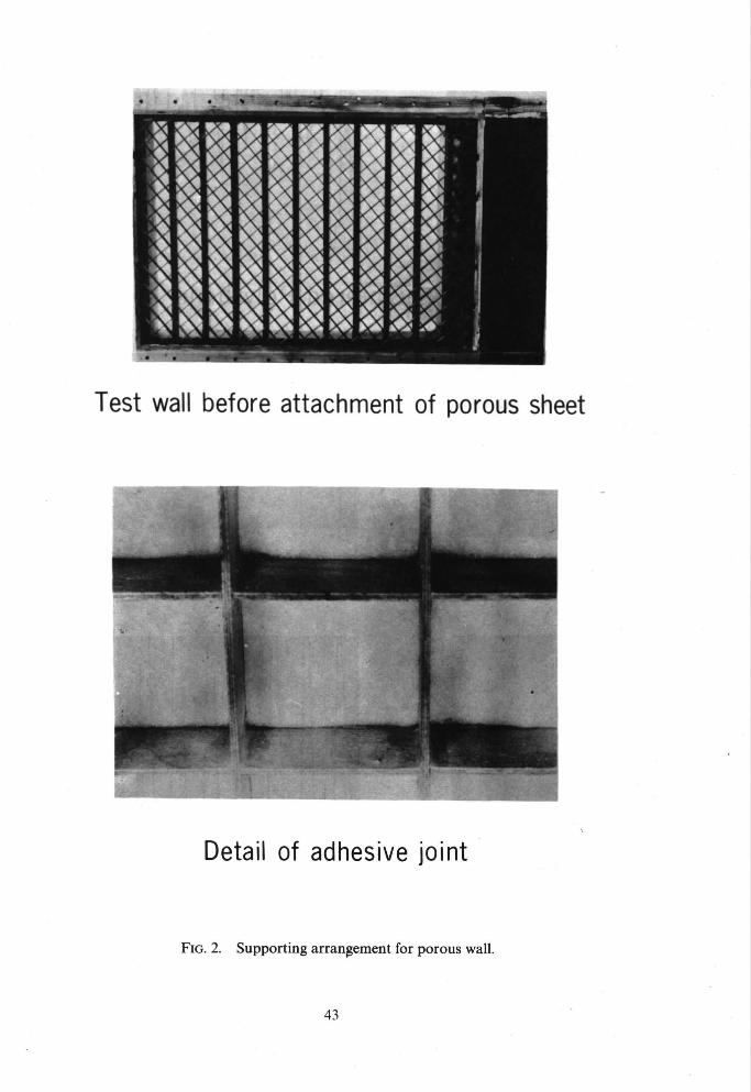
Test wall before attachment of porous sheet
7 . ,
Detail of adhesive joint
FIG. 2. Supporting arrangement for porous wall.
43

'Vyon' Sintered Polythene
r. i
rf
'Porosint' Sintered Bronze
'Poroloy' Stainless 0"005 in
! S C A L E
Steel Wiremesh 0"05 in
t I H O R I Z O N T A L
0'001 in I
V E R T I C A L
FIG. 3. Comparison of 'Vyon' with alternatives.
44

FIG. 4. Microphotograph of 'Vyon' taken on the Cambridge University scanning electron microscope.
45

[ -~ / 2 inlx 3inlx 1/4 in, CHANNEL
III • ~RUBBER SEAL / , ~ TO~ANOBOTTOM
~VYON' SHEET 1 \1/8 in. ORIFICE PLATE
LINE OF VELOCITY TRAVERSES
-- 32in. SHEET wIDTH ] /
FIG. 5. Apparatus used to measure variation of porosity along porous sheet.
1.0
-8 LOCAL V o MEAN
1.2
1-0
-8
I i I
* Variation along first Vyon sheet
o second ,,
0 O 0 0 0 0 0 0
0 0
0 0
÷ ÷ ÷ ÷ ÷ ÷ 4"
÷ 4"
L. Extent of Injection Surface I ~ 2'0 3'°
X in.
FIG. 6. Variation of Vo along centreline of test wall.
40
46

' 5
. 4 ¸
' 3
U/u,
' 2
i~'~' CONTOURS U/u1 AT O'F y=.010 in. FIR CONSTANT PRESSURE LAYERS AT Ul=50ft./sec.
\ ' - - - \ \ \ \ ~ \ ~
i "\ \ " \ " /u=°°~7 \ \-.f\ .... \ - - . ~ . ~__._ ',Soo_.j ~
. ~ VO/ul=-0 046 \ - - - - ~ ~ . ~ . ~ .
"~.~.\ % : .oo8
. ~ - ~ 1 . ~ . _ ~ . . .
. . / \ V o DISTRIBUTION FOR FIRST VYON SHEET
,6 Z'O X in. 3o
FIG. 9. Comparison of Vo distribution with u/U~ variation at constant wall distance.
1.2 .OC~L V o ~ N Vo -0
)-8
i I
I
I I
9 c
o
~ o
.O
'C.
E c-
E
o o
o6
o
p~ (.I o
~c
47
\
>o
-r
i
ii
- \ "0
O
!
x
o O
,. ~-q

10
o o '- 5 X
131"
¢ o
ET
I a; l i t
O" v
0
! !
Suction
Valve Orifice Plate
~ o Entry qse = Ftow Rate from Streamtined
k~ " " Entry assuming C d=l
~ o qo.p.=Flow Rate from Orifice Plate
o ~ assuming Cd=.6(B.S. 1042)
1"0 2-0 qs,e. ft'3/sec"
"3
Streamlined
3"0
A =
B =
Flow Rate for Layer with
do.
V O / u = .0017, Ul=50ft./sec. 1
Pressure Distribution !
C ~.
D=
E:
d o .
do.
do.
V O / u ='0032 Ul=50f t . / s ec . I
\%1= "0046, UI= 50 ftJ sec.
~IVo/u1 = .008, UI=50 ft./sec.
1 LPressure Distribution I]
FIG. 10. Compariso n of streamlined entry with orifice plate.
48

qD
1.02
~r,f
1.01
1.00 0
I I
Measured Velocity.Distributions
Mean Curve used in Ca Icu Ia t ions - - -~ i ~ . ~
• . ~ . ~ \ . ,/u~ oo46, u1:5o ,t./sec.
v / " " ~/U1=.0017, Ul=5Oft./sec.
; .... . . . . i
Mean Boundary Laye Th n Bo h Cases ... 1- in.
, , I I I 10 20 30
Xin. FIG. 11. Examples of velocity distributions.
40

O ¢..
O "." u
E
u, 2 L
ul ul
~ ' 1
° ~
n
0 ~
<
.4
-3
'2
0
m 'I l I I I I t
5panwise Pitot Pressure Dis t r ibut ions at l in. f rom Tunnel
Wall for Boundary Layer of Pressure Dis t r ibut ion I I I
O
4.
Cy l inder C e n t r e l i n e s
Pressure D i s t r i b u t i o n at 12in. d o w n s t r e a m
. . . . . . 28in. ,,
o o 0 0
0 0 0
0 0 0 0
0
O
O
0
ooo o
7ero for Upper
Distributions .>
+ 4. 4.
+ 4-
÷ + 4.
+
4.
+ ÷
+4"
4.4.
4. 4.
+
0 0 0 0 0
0 0
0 0 0 0
0 0
0 0
0 0
0 0
0 O0 0 0 0 0
4. 4.
4. ÷
4. or ÷ 4.
4. +
+ 4. 4"
4. 4. 4"
4" ÷ ÷ ÷
I
4.
O
O
O
O
%0
4"
4"
4"
+
+
4-4. 4.
L
6
A l 1 I I'~. I I I
7 8 9 V l l 12 13 I
14 15
FIG. 12. A typical result of two-dimensionality tests.
50
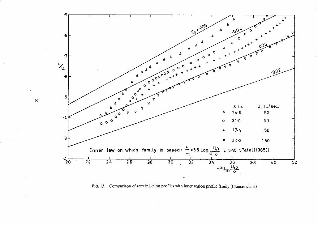
"9/ , , , , I , i
) . . .L
"8
q
"6
.5
"4
"3
-2 2'0
A
0 ° 0
0 0
A A
J A & A
O +
v v v
&
+ ÷ +
6
÷ ÷ ÷
I n n e r t aw on w h i c h f a m i t y is b a s e d :
I I I I I 2-2 2-4 2"6 2.8 3"0
O
÷
&
A
A
A
A ~ J O ° 0 A + +
J 0 0 + + +
0 + V + + + ÷ V
t - X in.
A 14"5
o 31.0
+ 17.4
v 34.2
~ " =5"5 Log lo + 5'45
I I I 3.2 3"4 3.6
UtY L°g lO 9
÷ +
+
+ +
÷ ÷
÷
+ ÷
÷ +
U I f t . / sec .
50
50
150
150
(Pa te r (1965) )
1 l 3-8 4"0
vl
4"2
FIG. 13. Comparison of zero injection profiles with inner region profile family (Clauser chart).

"08
"07
'06
ein.
"05
• 04 -
"03
.02
"01
°1,
Catcu Ia ted d e v e l o p m e n t s of
, C t a u s e r c h a r t
P r e s t o n t u b e
O u s i n g cf f r o m :
o U i = 50 f t . / s e c .
® Uj = 150 f t . / s e c .
I I 20 30
X i n . 40
FIG. 14. Comparison of calculated momentum developments with experiment.
52

i'6 I 1
1.5F
H
1.z~!
1.3 [- I
0
I I , , i '1\ qx,a,v Data of DUTTON ( 1 9 5 5 )
,, \ . ÷ P r e s e n t Data
÷ o ' ~ . . . . . \ COLES ( 1953 )
~ _ _ LANDWEBER (1953 )
V . ~ + + - - ' " ~ " ~ , - - ¢._* ÷
X
I I I I I . I I , I I I • 5 1 1.5 2 2.5 3 3.5 4 /-,'5 5
Rex10 -3
FIG. 15. H vers. Re for zero injection data.
[
"0024 F
.~ 0f//22 0 i
"0016 t
• 0 0 1 2 R , 0
.•, I ' °,X,~',lV, a ' D a t a o f ' D U T T O N ' ( 1 9 5 5 ) I ' , + P r e s e n t Data
- - - - - SQUIRE and YOUNG (1938 )
+ ' ~ ' ~ . - - - - - - - SCHOENHERR ( 1932 ) "~+ ' t~ '4~ , "~ - - - , ~ - - COLE S (1953 )
4-
I I I , I I I I l, i t • 5 1 1-5 2 2"5 3 3.5 4 ~-5 5
ReXl0- FIG. 16. C~r/2 vers. Ro$or zero injection data.
7 0 0 - - I I I 1" I I " I I I " I
600
200
100 Ulk " - 0 - f o r layers at U l = 1 5 0 f t . / s e c ,
Range of cf fo r [ayers at U i =150 ft . /sec.
'Y ~P " " '~ " U I = 5 0 f t . / s e c .
- " ,, " U] = 50 f t . / sec . ' I ' ~} I I ' b '
-001 "002 "003 "0 4 "005 -006 -007 -0 8 -009 "O 0 vo ui
FIG. 17. Variation of sublayer thickness with vo/U1 and cy.
53
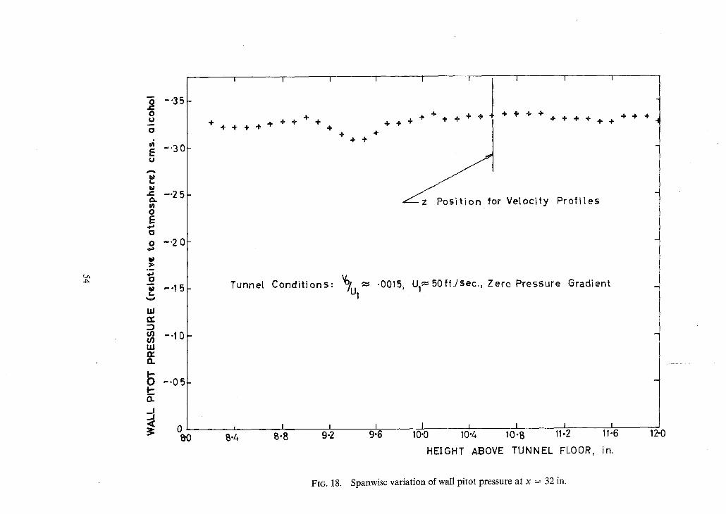
( I I I I I I I 1
t ~
.~ -'35 O I.)
O
E -'30 u
-~ -'2 5 0 .
0 E 0
o -'2 0
U
O "~ --1 5 I . .
1,1
-- I 0 u.i IX
1~ - ' 0 5 I-
5
÷ ÷
÷ ÷ ÷ ÷ ÷ ÷ ÷ ÷ ÷
Tunne[ C o n d i t i o n s :
' ~ I I 3: 0 , ....
B'0 B.4 B-8 9-2
÷ ÷ 4- ÷
+ ÷ ÷ ÷ ÷ ÷ ÷ + + ÷ ÷ + + ÷ ÷ ÷ + + + ÷
~ o r Velocity P r o f i l e s
V ° / U ~- .0015, U l~50 f t . / sec . , Zero Pressure Gradient 1
I 1 l I I 9"6 10"0 10-4 10-B 11-2 11-6
HEIGHT ABOVE TUNNEL FLOOR, in.
-4, ÷ ÷
12-0
FIG. 18. Spanwise variation of wall pitot pressure at x -- 32 in.

- - 0 0 3
- "002
d
-o
CL
--0011-
• An er ror in the measurement of Pl of 0-1% of ~2~U~ rep resen ts
about "0006 on the o r d i n a t e
o
o
0 0
0 0
the m o m e n t u m i n t e g r a l e q u a t i o n
of + -00005
0 L' I I I
15 20 25 30 X in .
FIG. 19. Distribution of integral in Newman's 'B ' term.
-2 I 1 , I i i i i
o
1/ '° u: ' ' ° ° - • E r ro r in ~U 1 throucjh assumincj
p = c o n s t a n t =Pc)' x 100
Edge I of Bounda ry Layer ~ . 3 5 i ? . I
B~ -0'5 .1 .1 s -2'~ .3 -3~ -4 ' .~ Yin.
FIG. 20. Static pressure difference profile and error in u/U1 profile.
;~6~' ~ Pressure Distribution from W a l l Tappings ' P_/£./ 0 . . . . . . Static P r o b e at y = 0 r e t | . ,, ,, ,, Y =
1"02 ~ . ~ . . _ j L ...s" " " " " ~ / - \ / ; v , I v , ,9 " - - . / v " \ _ 1 " 9 o o/ ,--oo31
1-0
I 1 I i 15 20 25 X . in. 3 0
FIG. 21. Comparison of static pressure distribu- tions.

.04
.0
Y in .
.02
.01 ¸
i i i I i i
I / - - S e l l o t a p e str ip
--V j, • .1 in. downstrea (Symbol
z___..O8in, upstream (Symbo l 4.)
o)
0 0 0 + +
0 o
÷
4-04" o
4" ÷ 0
0 4"
~¢ , I I I I I I • 35 "4 '45 -5 -55 .6
÷
o
4"
O
1
I ,65
FIG. 22. Effect of sealing strip on velocity profile near the wall.
4-
0
4-
o
0
-7
1"04
U 1
Uref
1.3 2
1-00
I I
Mean curve used in ca lcu la t ions
' J
I I I 10 20 30 X in. 40
FIG. 23. Experimental velocity distribution.
56
Printed in Wales for Her Majesty's Stationery Office by Aliens Printers (Wales) Limited
Dd 135646 K5

R o & M. NOo 3549
((~) Crown copyright 1968
Published by [:IER MAJESTY'S STATIONERY OFFICE
To be purchased from 49 High Holborn, London w.c. l
13A Castle Street, Edinburgh 2 109 St. Mary Street, Card i f fCFl IJW
Brazennose Street, Manchester 2 50 Fairfax Street, Bristol BS 1
258 259 Broad Street, Birmingham 1 7 11 Linenhall Street, Belfast BT2 SAY
or through any bookseller
Ro & Mo N o . 3549
S.O. Code No. 23-3549