expert system: a design methodology
TRANSCRIPT

Comput., Environ. and U&an Systems, Vol. 16. pp. 2141, 1992 Printed in the USA. All rights reserved.
0196-971992 $5.00 + .OO Copyright 8 1992 Pergamon Press plc
EXPERT SYSTEM: A DESIGN METHODOLOGY
Arif N. Merchant
Department of Urban and Regional Planning, Florida A t/antic University
ABSTRACT. This paper discusses the development of a design methodology that combines concepts from the fields of expert systems, urban design, and decision theory from the social sciences. More specifically, an evaluation technique, taken from decision theory, is merged with expert system techniques to create an innovative method of manipulating design knowledge and values. This research has demonstrated that the domain of urban &sign, though highly subjective, is an appropriate subject for expert system development.
INTRODUCTION
An urban design solution is the result of a continual feedback between exploration of urban form and evaluations of program, structure, and other technical issues. The designer’s inten- tions are formulated from a strong sense of images and, from this,, a conceptual solutioxi is developed. During the evaluation of this solution, conflicts arise because of the design con- straints imposed by prevailing site conditions, project requirements, and development regula- tions. This is a simplistic view taken to accommodate the limitation of the system at this time. It is not intended to downplay the importance of constraints related to social, economic, and political factors.
Each stage of the design process comprises logical analysis and conjecture. The nature of the design process creates challenges in two specific areas of the urban design activity. The first concerns the idiosyncrasies of individual designers. The second is the setting of the urban design activity. The idiosyncrasies arise from the different ways designers look at various aspects of a design and their own recollections of past images of other design projects. Some designers emphasize the massing of buildings, others the functional aspects of a design, and yet others emphasize the space contained by the buildings. The setting of an urban design activity is the product of prevailing site conditions, project requirements, and development regulations. Given the changing physical character of the city, traditional development and zoning controls are not sufficient to produce good urban form. Traditional development controls concern them- selves with “preventive measures of land use and building use” (Gosling, 1990) to the extent of
This research was carried out at the University of Cincinnati. The university’s support is greatly acknowledged, as are the comments from Samuel Noe and Dr. Samuel Sherrill. AutoCAD and AutoLISP are registered trademarks of Autcdesk, Inc. Concept is a registered trademark of Micro-Vector product.
Reprint requests should be sent to A. Merchant, Department of Urban and Regional Planning, Florida Atlantic University, Fort Lauderdale, FL 33301.
21

22 A. N. Merchant
specifying architectural detailing such as facade material, color, or the window details. More functional procedures of control have been exercised in the form of urban design guidelines in cities such as New York, San Francisco, Baltimore, Philadelp~a, and Boston (Gosling, 1990). The urban design guidelines take the form of rules governing parameters such as building heights, floor area ratios, and plot configurations. The nature of the urban design process is subjective, and there is a need to identify rules or guidelines that logically express the subjec- tive intents of the designer. These rules will help to resolve the conflict that exists between cre- ative thinking and logical analysis and, thus, reduce the gap between the subjective and the objective realm of the urban design process.
Time constraints are another challenge to the urban designer. In complex urban design prob- lems, there are too many potential design solutions to explore in a limited amount of time. At the risk of compromising creativity, the designer must decide what to try and what to ignore.
The problems described above, intrinsic to the traditional design process, could be reduced considerably by utilizing computer-aided design and expert systems techniques. First, there is the need to deal with designers’ i~os~cratic approaches. Second, recollection of visual pic- tures and related information associated with design ideas must be facilitated. Third, there is the fascinating problem of expressing rules internally; rules that are at once both logically con- sistent and holistically coherent. Fourth, there is a need to expedite evaluation of such rules for various design alternatives.
This research attempts to address all of the above problems by developing a design method- ology that combines concepts from the fields of expert systems, urban design, and decision the- ory from the social sciences. In the most aggregate sense, the attempt here is to integrate com- puter and social sciences with the art and science of urban design. More specifically, an evalua- tion technique, taken from decision theory, is merged with expert system techniques to create an innovative method of manipulating design knowledge and values.
In the early stages of this research, the focus of the Urban Design Expert System @IDES) was on the creation of a tool to aid the urban design process as it pertained to the satisfaction of design standards. But as development of UDES progressed, the emphasis had to be devoted also to the simulation of the idiosyncrasies of designers. UDES now incorporates both of these fea- tures and offers advice on the conformity of a design to the design rules and design paradigms.
The research uses the designing of an urban space, e.g., a plaza, as a typical problem solving situation in urban design. This paper discusses the prototype UDES developed during the course of this research. The style of this discussion follows that of Davis, Buchanan and Shortliffe (1985). It gives a comprehensive overview of the UDES system. To begin with, fea- tures essential to any urban design knowledge-based system are reviewed. This is followed by the explanation of the system structure and its fundamental assumptions.
SYSTEM GOALS
The UDES system was developed to provide advice on the conformity of a design to design rules and to design paradigm(s). The decision to construct an artificial intelligence program in the urban design domain brought with it several demands that have shaped this project.
First, the program had LO be useful if it was to attract the interest and assistance of design experts. To recall, every designer emphasizes a different category of criteria. For example, one designer might consider spatial quality of a design more important than the circulation aspect. Another may consider circulation more important than spatial quality. There is the need to deal with this idiosyncratic approach of designers. This is reflected in the choice of evaluation tech- nique discussed in the following section.
A second demand was the need to express rules internally, in a way that is both logically consistent and coherent. A majority of urban design rules can be represented as IF..THEN

Expert System: A Design Methodology 23
statements (Merchant, 1990). The choice of a production rule system was significantly influ- enced by this feature of the knowledge base.
A third demand was the need to expedite evaluation of various design alternatives. In addi- tion, the choice of an urban design domain imposed its own unique demands. The program must fill needs well-recognized by designers who would actually use the system. As noted earlier, a design product is influenced by initial design ideas in the form of organizing principles, rules, and images of previous design projects experienced personally or observed. During a design process, persistent images continuously reinforce the design solution, while others, that appear only intermittently, have more peripheral influence. There is the need to facilitate recollection of these images. Also, ease of software use is important owing to the limited technical capability of urban designers. Finally, the program had to be designed with an emphasis on its supportive role as a tool for urban designers, rather than as a replacement for their reasoning process.
Any system developed had to meet all these demands. Predictably, some have been met more successfully than others, but all have been important factors in influencing the system’s final design.
CHOICE OF AN EVALUATION TECHNIQUE
Based on the San Antonio River Walk Advisory Commission Report (1987), the Urban Design Plan of San Francisco (1970), Urban Systems Research and Engineering, Inc. (1977),
and Lynch (1981), five criteria for urban design evaluation were identified. They are spatial definition, building form and massing, circulation, activity support, and aesthetic. The quality
of a design is determined by the extent it satisfies the rules (design guidelines) that promote each of the these categories of criteria. All rules do not contribute at the same level to the ful- fillment of a design goal based on these categories of criteria. Some contribute more and are, therefore, more important to a design performance; others contribute less and are less impor- tant. The evaluation of a design solution calls for an evaluation methodology that makes it pos- sible to incorporate multiple goals in the evaluation process.
Multiple Attribute Utility Technique (MAUT), based on decision theory, makes it possible to integrate design and evaluation and to provide continuous feedback. It is essentially an evaluation of outcomes where values in numerical form are attached to outcomes. The essence of MAUT is that each rule to be used for the evaluation of design is judged for its rel- evancy to each of the categories of criteria identified earlier - spatial definition, building form and massing, circulation, activity support, and aesthetics. This relevancy can be deter- mined by a procedure that may consist of experimentation, judgment, or some combination of these. The weights of the categories of criteria are also determined. These weights are judg- mentally-obtained numbers that describe the importance of each of these categories to a designer. The resultant weight of the rule is then a combination of relevancy measure and weights of the categories of criteria (Edwards, Guttentag, & Snapper, 1975).
The implementation of MAUT comprises five steps. This is shown in Figure 1 and dis- cussed below.
1. Identify the aspects of the design to be evaluated: As discussed earlier, the quality of design solutions depends on how well the rules (design guidelines) are satisfied. Therefore, establish a list of all applicable rules related to each of these design aspects. For example, Rule 35: The heights of the buildings should be uniform, i.e., should not vary by more than 25%.
2. Identify the relevant categories of criteria: As discussed earlier, five categories of criteria have been identified - spatial definition, building form and massing, circulation, activity support, and aesthetic. Every design is evaluated based on these criterion categories. The

24 A. N. Merchant
number of these categories (five) conforms with the recommendation of Edwards et al. (1975) that such a number should not exceed eight. If there are many categories, and if there are some that are very much more important than others, and if 100 points are dis- tributed over such categories, then less important categories will have trivial weights.
3. Rate the importance of each criterion category: Every designer perceives a design in a dif- ferent way. The differences in the evaluation of a design can be attributed to the level of importance given to each of the these criterion category. One group of designers empha- sizes spatial definition, another emphasizes activity support. This step rates each of the criterion category in importance according to one’s own design philosophy. The choice of scale for rating is arbitrary. One can choose a O-to-100 scale or a O-to-10 scale or any other scale. Gn a O-to-100 scale, how different is a criterion category if it is rated 51 or 52 or 53? Larger scales impose more choices making the interpretation of a number as a value more difficult. Keeping this in mind, a O-to-10 scale was chosen, 0 being the least important, 10 the most important. Again, this is arbitrary. A O-to-7 scale could have been chosen instead. For example, on the scale of 10, spatial definition is rated 10 (WI), build- ing form and massing 8 (wz), circulation 6 (WY& activity support 7 (~4). and aesthetic 6 (wg). These ratings (10, 8,6, 7, and 6) can be referred to as paradigm weights. “Paradigm” is used in the general sense that Kuhn (1970) defines it - referring to, in a design context,
a particular theoretical perspective or approach in design (for example, Bauhaus, Team 10 Primer approach, Rationalist approach).
4. Measure the relevance of each rule to each criterion category: This is a subjective step where the relevance of each rule to each of the criterion category is estimated on a scale of O-to-4, 0 being no relevance at all and 4 being the greatest relevance. A O-to-4 scale was chosen for the same reasons described in the earlier step. For example, the contribution (u) of Rule 35 to each of the design criteria is measured as:
spatial definition I (u35 1) building form and massing 3 (~35, 2) circulation 0 (u3593) activity support 0 (u354) aesthetic I (u355)
The above contributions of each rule to criterion categories will henceforth be referred to as criterion weights.
5. Calculate the weights for rules: The equation is
Wi = < WjUij
where Wi is the aggregate weight of the ith rule, wj is the importance weight of jth criteri- on category, uij is the relevance of the ith rule to the jth criterion category, and N is the number of categories of criteria. For example, the weight of Rule 35 is given by:
W35 = (10 x 1) + (8 x 3) + (6 x 0) + (7 x 0) + (6 x 1) = 40
There is no claim in the above discussion that different designers will come up with simi- lar numbers. Such consensus is indeed rare. In the application of MAUT to building per- mits evaluation, Gardiner (1974) has determined that the magnitude of interpersonal dis- agreement produced by this method is less than that produced by simply arguing about what to do. Group evaluations were collected for 14 permits from two groups of subjects reflecting different viewpoints. He determined that these groups differed significantly (12% variance) when holistic ratings were compared, but this difference virtually disap- peared (2%) when MAUI was used. Edwards et al. (1975) in holistic evaluations attribute

Expert System: A Des@ Methodology 25
wide differences to those with strong points of view who are inclined to focus on those aspects of the design being evaluated that most strongly engage their prejudices. But the multi-attribute procedure does not permit this: It separates judgment of the importance of a design criterion from judgment of how well a particular rule is relevant to that criterion
category (Edwards et al., 1975).
In relation to the five steps of MAUT discussed earlier, two kinds of disagreements may be identified - one in determining criterion weights in Step 4 and the other in determining the paradigm weights in Step 3. Disagreements at Step 4 involve judgment of each rule’s relevancy to a criterion category. Edwards et al. (1975) recommends that these judgmentally-determined scores should reflect expertise and, therefore, should be obtained from urban design experts. Disagreements at Step 3 involve judgment of the importance of each criterion category. These are the essence of conflicting values that reflect a design paradigm, i.e., idiosyncrasies of a designer or a design approach, and should be respected. Again, no claim for reducing interper- sonal disagreement to a zero is made, but reduction in disagreements is very likely.
SYSTEM OVERVIEW
The fundamental task is the design of an urban space - a plaza. Consultative advice is often required while designing because the designer is not always an expert; for example, a student may be carrying out a design project as a studio assignment. Time considerations compound
STEP 1 Identify the aspects of the design to be evaluated. Establish a list of all applicable @@rules" related to each of these aspects.
____________________~~~~~~~~~~~~~~~~~~~~~~~~~~~~~~ xample Rule35: The heights of the buildings should be
uniform, i.e., should not vary by more than 25%.
STEP 2 Identify the relevant categories of criteria embodied in the collection of rules.
____________________~~~~~~~~~~~~~~~~~~~~~~~~~~~~~~ viz. Space Form Circulation Activity Aesthetic
STEP 3 Rate these criteria in importance according to your own design philosophy (paradigm weights) ____________________~~~~~~~~~~~~~~~~~~~~~~~~~~~~~- Space Form Circulation Activity Aesthetic
:xample 10 8 6 7 6 (on a O-10 scale: 0 is least & 10 is most imp.)
STEP 4 Measure the relevance of each rule to each criterion category (determine criterion weights) ____________----------~~~~~~~~~~~~~~~~~~~~~~~~~~~~
lxample Rule35: The heights of the buildings should be uniform, i.e., should not vary by more than 25%.
Space Form Circulation Activity Aesthetic 1 3 0 0 1
(on O-4 scale: 0: no relevance to 4: greatest relevance)
STEP 5 Calculate the total weights for each rule. (Summation of paradigm wts. x criterion wts.)
____________________~~~~~~~~~~~~~~~~~~~~~~~~~~~~~~ Category Rule
;xample Space Form Circ. Activity Aesthetic Weight 10x1 + 8x3 + 6x0 + 7x0 + 6x1 = 40
FIGURE 1. Five steps of MAUT.
26 A. N. Merchant
the problem. A designer typically tries to recall and replicate relevant features of images he or she believes will contribute to the current project. As evident from the previous discussions on design process, the quality of the final design is a product of the interaction of recalled images, design principles, guidelines, and design constraints.
A great deal of attention has been paid to making the UDES interaction easy and natural. In some cases, multiple choice questions have been chosen to facilitate decision-making on the part of a designer. In other cases, responsibility for a design decision rests with the individual.
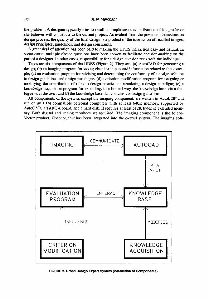
There are six components of the UDES (Figure 2). They are: (a) AutoCAD for generating a design; (b) an imaging program for seeing visual examples and information related to that exam- ple; (c) an evaluation program for advising and determinin g the conformity of a design solution to design guidelines and design paradigms: (d) a criterion modification program for assigning or modifying the contribution of rules to design criteria and simulating a design paradigm; (e) a knowledge acquisition program for extending, in a limited way, the knowledge base via a dia- logue with the user; and (f) the knowledge base that contains the design guidelines.
All components of the system, except the imaging component, are written in AutoLISP and run on an IBM compatible personal computers with at least 640K memory, supported by AutoCAD, a TARGA board, and a hard disk. It requires at least 512K bytes of extended mem- ory. Both digital and analog monitors are required. The imaging component is the Micro- Vector product, Concept, that has been integrated into the overall system. The imaging soft-
DATA INPUT
\I/
EVALUATION , INTERACT , KNOWLEDGE PROGRAM \ / BASE
/ /\ /\
INFLUENCE
CRITERION MODIFICATION
1 MODIFIES
FIGURE 2. Urban Design Expert System (Interactlon of Components).

Expert System: A Design Methodology 27
ware operates in the Autocad shell and requires 70K. Images are digitized 35rnm color positive scanned by a Howtek 35 slide scanner. The images appear on an analog monitor while
AutoCAD runs on the digital monitor. Thus, both can be viewed at once. For the purpose of the discussion of the UDES, the program components are grouped into
three categories. The first category comprises the components that are directly related with the design process of the user: They are AutoCAD, the imaging program (“Concept”), and the evaluation program. The second category includes the components that are necessary to main- tain the system, that is, modify the knowledge base and the criterion weights of design rules. The final category is the knowledge base itself. The description of the system ends with the discussion of the inference mechanism.
THE DESIGN PROCESS IN UDES
Figure 3 shows a typical design process using the UDES. The user begins to design in AutoCAD and may make repeated calls to the imaging system for visual support. When the design is complete or partially complete, the user may decide to evaluate the design with respect to a desired aspect of the design. The user then returns to AutoCAD, and the process continues until the completion of the design. The three components - AutoCAD, the imaging program, and the evaluation program - associated with this design process are discussed below.
EVALUATION PROGRAM
A
EVALUATE
\ ,
DESIGNER 8, EVALUATE
RECALL IMAGES
FIGURE 3. Deslgn Process in UDES.

28 A. N. Merchant
AutoCAD
The AutoCAD system, per se, is not discussed here in detail. The assumption is made that the user has a working knowledge of this program. The discussion on AutoCAD is limited to the description of design macros and menus implemented for UDES. As shown in Figure 4, a designer can use menu options to interactively add design elements. Only those elements have been programmed that have design rules/guidelines associated with them. The design elements
currently available are buildings, ground cover, trees, water fountains, seating provisions, game tables, bicycle parking, and play apparatus. To recall, the prototype problem is the design of a plaza. The purpose of limiting UDES to nine elements is not intended to inhibit the designer’s creativity, but to save time in recalling related design standards and making pertinent informa- tion available to the evaluation program in the correct format.
In the design process of a plaza, the designer is faced with the problem of locating an activi- ty in the space. One of the factors that influences location of an activity is the type of spatial enclosure. For example, if an activity is located at a point where the surrounding buildings are overpowering, then it will create a claustrophobic feeling, and the desired use of the space will not be achieved. To facilitate decision-making, the program allows the designer to determine the types of activities that can be located in the space. The process is interactive and is activat- ed by the selection of a menu option.
The Imaging Program
As discussed earlier, every designer, consciously or subconsciously, relies on previous design ideas or precedents. This is often in a form of mental recollection of a visual picture of that design idea. At times, there is an ongoing process of replicating such a visual picture. To facili- tate the recollection of visuals, the system interfaces with another program called Concept. During the design process, the user can refer to any specific visual image(s) currently available in the image inventory. The images have information related with design standards attached to
Space Evaluate Tool8 FramaKdl File Help AutocAD l ***
Blcycls Partii~ _--_--_-
Select objects: cammd: mdrur comand:
FIGURE 4. Design Elements In AutoCAD.

Experr Sysfem: A Design Methodology 29
slantity Rtivith CfratlAtIa PAtterns
FIGURE 5. Options for Visual Support.
them and can be interactively viewed as desired. This information can be on plot configura- tions, building frame heights, provision of activities, or materials used. It provides the designer with useful comparison to the design underway. While in Concept, the user can explore any or all of the stages related to the design process of a plaza utilizing a visual environment.
The user can activate this program by using the menu options and has a choice to recall any specific visual picture or review any stage of the design process. The number of images cur- rently available are few because of the limitation of storage space on the system. A sample ses- sion is shown in Figures $6, and 7.
The Evaluation Program
This component of the UDES offers advice on the conformity of a design to design rules and design paradigm (approach). As discussed earlier, every designer looks at a particular design from a different angle. This is especially true for designers with strong points of view, who are inclined to focus on those aspects of the design being evaluated that most strongly engage their prejudices. This program allows the designer to select a design approach for its evaluation. There are two such design paradigms, labelled as Designer-A and Designer-B, currently avail- able in the system. This does not limit the capabilities of the system because there is also an option that allows the designer to specify his or her prejudices of design aspects (Figure 8). The evaluation program is completely menu driven and requires no technical expertise on the part of the user. The designer first specifies a design approach (paradigm), and then the design aspect (that is, criterion category) - visual, activity support, circulation, overall - he or she desires to evaluate. In the evaluation of the design, the designer interactively answers the ques- tions posed by the system.
The overall results (Figure 9) reflect the design paradigm used and are always compared with the default approach. The default approach considers all design aspects to be of equal importance and, therefore, provides a base-line for comparing other approaches. This is useful in cases where a decision on a design acceptance is desired by a group of designers. In such

30 A. N. Merchant
FIGURE 6. Select Image to Visualize.
cases, if the scores of various designers are about the same as the default approach, then there is no question of acceptability of the design; otherwise the scores are helpful in determining the degree of differences among various designers. Complete evaluation of applicable rules is shown in Figures 10 and 11.
FIGURE 7. Fountain Square, Clnclnnatl.

Choom lkdas for Eualtcatlan: Uiaual Character of sita Pmuision of hctiultlar
All De8lgn Chuuhristia
Cl- lksdtv to Ulw Uhual Chrrcbridic8
of hctiuities
Expert System: A Design Methodology
,
DIN: DISPLAY DRAU RD17: lNuuIRY
Ws Carrand: rowm fsquanl.uid Conand :
31
FIGURE 8. Choose a Design Approach.
SYSTEM MAINTENANCE
Figure 12 shows a typical process of modifying the UDES. The user begins in AutoCAD and may decide to either modify the criterion weights associated with any of the design rules using the criterion modification program or define new rules or modify rule descriptions using the knowledge acquisition program. Each of these components will be discussed.
VISUAL ACTIVITY CIRCULATION OVERALL
DEFAULT 0.32 0.57 0.0 0.45
DESIGNER-B 0.32 0.59 0.0 0.51
With respect to VISUAL characteristics the design conforms ABOUT THE SAME to both the approaches.
With respect to ACTIVITY support the design conforms ABOUT THE SAME to both the approaches.
With respect to CIRCULATION support the design conforms ABOUT THE SAME to both the approaches.
The overall design conforms ABOUT THE SAME to both the approaches.
,
FIGURE 9. Overall Evaluation Results.

32 A. N. Merchant
Rule59 has determined that the number of trees required to be planted are 2.0.
Rule42 failed.... The length to width proportion of this plaza is greater than 2.5. This will cause the space to leak out.
Rule43 successful with strength 1 Stationed at the center of the plaza, the buildings will not seem overpowering in the space. Also, sunlight will not be restricted into the space.
Rule44 has determined that stationed at the center of the plaza, one will feel fully enclosed. Facade details will tend to dominate the field of vision.
Rule47 successful with strength 1 Stationed at the center of the plaza, there is some sense of enclosure.
Rule48 successful with strength 1 The contained space has a good relation to the heights (average ht.) of the buildings. The external enclosuri will be very comfortable.
Rule49 failed.... Your building heights (between minimum 6 maims) vary by 100%. It should not be more than 25%. If it will help you resolve, the building heights are (15 15 20 20 20 30 30 30 30) feet.
Rule50 has determined that this is an intimate space with strength 1
Rule51 has determined that this is an urban space with strength 0.4
Rule54 has determined that the perceived height of the plaza is between 90 feet and 120 feet.
Rule61 successful with strength 0.5 You have provided 1 number of trees. Number of trees required by standard is 2.0
Design approach used this session: DESIGNER-B The design performance with respect to VISUAL is 0.44
If you use the default approach then the design performance with respect to VISUAL will be 0.44
FIGURE 10. Evaluation Results for Visual Aspects.
Criterion Modification Progran
This program allows the user to reassign criterion weights of any rule or assign weights to a new rule. By a simple bookkeeping mechanism, this program keeps a record of new rules being added and incorporates them into the list of rules to be invoked. The task is interactive and requires no programming experience. The program allows the user to input information regard- ing the relevancy of the rule with respect to each criterion category - spatial definition, build- ing form, circulation, activity support, and aesthetics (items l-5 in Figure 14). The user dso

Expert System: A Design Methodology 33
Rule21 failed.... You have not provided any drinking water fountain. This is a residential plaza. You must provide at least one such fountain.
Rule22 failed.... This is a residential plaza. You have made no provision for games tables. Provide minimum one table for 4 persons.
Rule23 failed.... This is a residential plaza. Therefore by standard you should provide 3 or a minimum of 1 play apparatus. You have provided none.
Rule 4 successful with strength 0.235107 The plaza is used as a walk thru. You have provided 23.0 feet of seating.
Rule 11 failed.... The ratio of total length of chairs and the total seating is greater than 1.0 The ratio is 2.6
Rule13 successful with strength 1 You have provided adequate seating for handicapped.
Rule15 successful with strength 0.24 Resting place has been provided with the above strength.
Rule16 successful with strength 0.67 The presence of (TREE ARCADE)has been detected in your design. Therefore the basic requirement for shelter provision has been satisfied.
Rule18 successful with strength 0.25 You have provided (PHONE-BOOTHS FOOD)
Rule19 successful with strength 1 There is provision for food facilities in this plaza.
Design approach used this session: DESIGNER-B The design performance with respect to ACTIVITY is 0.45
If you use the default approach then the design performance with respect to ACTIVITY will be 0.44
FIGURE 11. Evaluatlon Results for Activity Support.
specifies the category(ies) of rule under which the rule should be invoked (item 6 in Figure 14). These categories are visual, activity, and circulation. Visual category comprises the rules that are relevant to spatial definition, building form, and aesthetics. The three criterion categories are grouped together because there are few rules in the knowledge base that are relevant to form and aesthetics. Activity category comprises rules that are relevant to activity support, and circulation category comprises rules relevant to circulation. The trigger rule, if any, is also specified (item 7 in Figure 14). A sample session is shown in Figures 13 through 16.

34 A. N. Merchant
DESIGNER
KNOWLEDGE
MODIFY KNOWLEDGE BASE
ASSIGN CRITERION WEIGHTS TO A NEW RULE
FIGURE 12. UDES Modlflcatlon PToCeSS.
FIGURE 13. Modify Crlterlon Welghts.

Expert System: A Design Methodology 35
Assign/Reassign Weights to Rule number: 29
Rule29: IF the width of the space is lees than the height of the building, (D/H < 1) then the building becomes overpowering.
The existing weights for RULE29 are ((SPACE 4) (FORM 0) (CIRCULATE 0) (ACTIVITY 0) (BEAUTY 0) (CATGRY (VISUAL)) (TRIGGER TRUE) (RULES 29))
Which of the following criteria would you like to reconsider? Enter a number.
1. Spatial quality
2. Building Form h Hassing 3. Circulation 4. Activity Support 5. Aesthetic/Beauty 6. Dominant Category of Rule 7. Trigger Rule 0. Done
Enter a number: 7
FIGURE 14. Request for Visual Display of the Rule.
Layer 0 Drtho 1.138bME*83.67’-7 lY32”
TN. CO_OIyD w m- I.s_.
RuiOCRD I***
setup
BLOCKS DIM: DlSYUlY DRbY EDIT INPUIRY LAYER : SEIrII4Gs PLOT ucs :
FIGURE 15. Vlsual Display of the Rule.

36 A. N. Merchant
The existing weights for RULE29 ore ((SPACE 4) (FORM 0) (CIRCUIATE 0) (ACTIVITY 0) (BEAUTY 0) (CATGRY (VISUAL)) (TRIGGER TRUE) (RULE# 29))
Which of the following criteria would you like to reconsider? Enter s number.
1. Spatial quality 2. Building Form 6 Uassing 3. Circulation 4. Activity Support 5. Aesthetic/Beauty 6. Dominant Category of Rule 7. Trigger Rule 0. Done
Enter a number: 1 Enter space performance <0,1,2.3.4>: 3
Which of the following criteria would you like to reconsider? Enter e number.
1. Spatial quality 2. Building Form h Massing 3. Circulation 4. Activity Support 5. Aesthetic/Beauty 6. Dominant Category of Rule 7. Trigger Rule 0. Done
Enter a number: 0
The revised weights for RULE29 ere
((SPACE 3) (FORI 0) (CIRCULATE 0) (ACTIVITY 0) (BEAUTY 0) (CATGRY (VISUAL)) (TRIGGER TRUE) (RULE++ 29))
I
FIGURE 16. Modity Crlterlon Weights.
I
Knowledge Acquisition Program
This program allows the user to enter new rules. It has two components. One allows addition or modification of rule descriptions and the other allows definition of new rules. This program is activated by selecting the same menu option (Assign/Modify Rule Weights) from the pull- down menu as in the case of the Criterion Modification program. The Knowledge Acquisition program is functional only if the rule number being added does not exist. This is to ensure that the previously defined rules are not redefined. Both the components - adding the rule descrip- tion and defining the rule - are sequentially activated, followed by the Criterion Modification program. If the rule number already exists in the knowledge base, then the Knowledge Acquisition program is bypassed and only the Criterion Modification program is activated. The performance of this program is limited. New rules can be defined using only the predefined variables. For convenience, the user is always presented with the list of these variables prior to

Expert System: A Design Methodology 37
the selection of one. Currently, the program does not have the capability to carry out consisten- cy checking of the knowledge base. The assumption is made that total contradiction will not be entered by the user. Both of these components of the program use an interactive approach of knowledge acquisition.
THE KNOWLEDGE BASE
There is no actual or hypothetical empirical knowledge stored. The knowledge base includes nothing about the actual state of a given design and in some cases this knowledge is captured from the user during an interactive consultation. In other cases, knowledge capture involves much more than formalizing existing rules and interactive consultation. Specific routines have been ~plemented to extract each desired item (referred to as objects in the discussions to fol- low) from the design. As discussed under the AutoCAD component, the input of graphics information has also been formalized through a series of design macros or batch commands.
The type of knowledge represented can be categorized into:
1. Normative empirical knowledge are the rules governing the prescription of design princi- ples. For example, Rule 33: If DIH >= 4, then the balance between the building and the space dissipates.
2. Meta-knowledge is “the knowledge about the use and control of domain knowledge in an expert system” (Waterman, 1986). It is “how-to-do knowledge” about how the system operates or reasons. A meta-rule “is a production rule that controls the application of object-level knowledge” (Alberico & Micco, 1990). It is a “rule about rules describing how other rules should be used,, (Han & Kim, 1990). With the system’s cmrem collection of 40 rules, exhaustive invocation of rules may not be a problem. However, as the collec- tion grows substantially larger, problems such as slowing of execution time could occur. With this in mind, an example of meta-knowledge is shown below:
If the setting of the plaza is residential, then invoke the residential rules.
This meta-rule tells the system how to select the domain rule to execute. It performs a branching function by determining what sets of rules cau be invoked while excluding those that are irrelevant. This eliminates rules governing commercial plazas, thus, the amount of time needed to execute irrelevant commercial rules.
3. Modelling knowledge “concerns the relationships between other items of knowledge, especially empirical knowledge, and take the form of procedural rules” (Webster, Song, & Wislocki, 1989). The modelling knowledge stored are the expressions for deriving cer- tain standards and defining design concepts. For example, Rule 44: If a play apparatus is provided then the total number of trees to be provided can be reduced to half the required amount. or Rule 36: If the longitudinal dimension of an enclosed space is less than or equal to 80 ft, then the enclosed space is an intimate space.
The primary soume of domain-specific knowledge is a set of some 40 production rules, each with a premise and an action. Normative empirical knowledge can be further categorized into soft rules and hard rules. Soft rules are rules whose truth camiot be guaranteed but which is applicable on many occasions. The truth value of a statement is not, in general, yes or no, 0 or 1. It can have a degree of truth of being satisfied. A majority of rules in the urban design framework are soft rules that are suggested standards to achieve a good design solution. A design may conform to these standards partially and yet contribute towards a specific design goal. This means that the rules cannot be taken as absolute requirements to be satisfied, but only as standards for the design solution to meet to achieve total conformity. Hard rules are

38 A. N. Merchant
dichotomous: Either they are satisfied or they are not. The truth value of a statement is in gen- eral yes or no, 0 or 1. only a few such hard rules are required for design guidelines. Many of the design guidelines are soft rules. This significantly influenced the decision to implement most of the rules as approximates rather than exact since the information to be m~pula~d is imprecise (referred to as fuzzy logic). For example, Rule 34: If the ratio of the width of a space to the height of a building (W/H) is between 2 and 3, then the external enclosure is most com- fortable. This ratio in some cases may extend to 4 and is implemented as:
Premise: IFW,‘H>=2&<=3 IFw/H>4 ELSE
Action: THEN return a support value of 1 THEN return a support value of 0 Return a support value between 0 and 1, determined by linear interpolation.
IF support value > 0 ELSE
THEN Advice _.. Advice . . .._..
Each rule returns a support value that reflects the degree of conformity of a given design to that rule. The support value determines the advice given with respect to each rule evaluat- ed. Support values also play a significant role in the inference mechanism discussed later in this chapter.
In all rules, each clause of a premise comprises three components: ~a~ernati~~ function>, <variable>, and <values>. All rules have been implemented using the predefined mathematical functions of AutoLISP (e.g., =, /=, >, <, >=, <=, equal, member). There are over 100 such fimc- tions available in AutoLISP, only 8 have been used in the implementation of rules. Twenty-two variables (for example, PAREA [plaza area], MAXD [maximum perceived dimension], MAXHT [maximum height of buildings]) have been defined and are currently available for use as primitives in constructing rules. A variable may be used in more than one rules. Specific routines have been implemented to extract these objects from the AutoCAD drawing. Each rule is, as evident, highly stylized, with the IF....THEN format and the specified set of available primitives. Despite this strong stylization, the format is not very restrictive: Of nearly 40 rules implemented, only 5 employ any significant variations.
INFERENCE MECHANISM
The rules are invoked in a forward chain. The question that is always asked is: Given a design approach (paradigm), how well does the given design conform to visual, circulation,
activity support, or overall aspects of design? The user has an option to choose a design approach or specify his or her own approach. Given any such aspect to evaluate, the list of all rules whose conclusions bear on the given design aspect (i.e., that are relevant to me particular criterion category) are retrieved. For each rule in that list, if the trigger (conditional) rule is true (i.e., the support value of the trigger rule is greater than 0), then that rule is invoked. Its premise is evaluated and the conclusion made with a support value. For example, Rule 10: If it is a civic plaza and it is an urban space, then it should accommodate special gatherings which have a single focus of attention (such as performances, public speeches, etc.). The requirement for providing the special functions are dependent on the condition that the plaza be a civic plaza in an urban space. The degree that these conditions are true, i.e., that they lie anywhere between 0 and 1, is decisive in determining the importance of this rule and whether it should be invoked. If these conditions are met, then the design is checked for the provisions of these activities, else this rule is ignored.

Expert Sysiem: A Design Methodology 39
A given rule may be relevant to more than one category. For example, a rule might be rele- vant to &iv@ and circulation. The question that arises is: Under which category should this rule be invoked? Answer to this question is derived from the system’s meta-knowledge. If the design paradigm being used considers circ~~ti~~ to be more important than ucfiv~~ s~~~r~, then the above rule will be invoked under the circularion category.
The method of computation of the overall conformity of the design to any aspect of design is illustrated by the following example. Consider a knowledge base of 20 rules. When the infer- ence mechanism was employed, assume that 8 rules were found applicable to the given design situation and, therefore, invoked. Each rule was satisfied to a certain degree, returning a sup- port value to that effect. The following Table 1 shows the rules that were invoked, their corre- sponding weights (Wt) derived by using Multiple Attribute Utility Technique (MAUT), and their support value (SV) returned. Also shown are the conformity scores (CS = Wt x SV) obtained under the given circumstances, and the maximum possible scores (MPS) are the scores if the rules were fully satisfied (MI’S = Wt).
The above compu~tion method excludes rules not applicable to a given design situation and, therefore, allows for evaluation of partial designs.
APPLICABILITY OF THE UDES
The Urban Design Expert System is designed as a supporting tool and not as a replacement for the urban designers’ own creative and critical thinking. The system has potential applica- tion in several areas of urban design. First, it can be used as a learning tool by students. The imaging component, with its capability to quickly visually explore any or all of the stages relat- ed to the design process, further reinforces this potential. Second, it can be used by individual designers or design offices to determine the conformity of a design scheme to a set of design rules, as well as to a specific design paradigm. In offices, the design paradigms may reflect the design p~losop~es of the org~zation. The increasing trend in the use of computers in design offices increases the potential future use of systems like UDES. Third, there is a potential use for expediting the urban design review process. As discussed earlier, MAUT helps reduce dis- agreements among designers over a design scheme by making evaluation more explicit and understandable. Design scores of various designers for the given scheme can be compared to the default approach to determine the extent and areas of disagreement. However, this potential could be undermined by requiring all designs (or at least major designs) to be submitted in AutoCAD format for the urban design review. This is not feasible at present.
TABLE% CompufatlonofDesfgnScote
Rule # Weight Support Conf onnity Max Possible Value Score Score
wtt (SV) (cs=wtxsv) (MPS)
1 20 0.6 12.0 20 2 10 0.1 1.0 I.0 4 12 0 0 12 5 15 1.0 15.0 15 7 09 0.4 3.6 09 8 13 1.0 13.0 13 10 25 0 0 25 15 17 0.5 8.5 17
Total 53.1 121

40 A. N. merchant
Several scents in favor of using systems like UDES can be given. First, with growing reliance on computers in offices, it is a reasonable goal to expect greater emphasis on produc- tion of computer-aided designs in the future. Second, there are currently many design profes- sionals using computer-aided design who might not hesitate to take their computer equipment to the urban design review board and make a presentation to facilitate a more objective review. In such cases, UDES could identify disagreements among the Urban Design Review Board members. Or, it might reveal that the proposed design conforms to Board standards and is, therefore, acceptable.
CONCLUSIONS
This research combines concepts from expert systems theory in computer science and deci- sion theory from the social sciences to solve urban design problems. Multiple attribute utility analysis from decision theory is used to evaluate design solutions that have multiple goals. Expert systems provide techniques to manipulate the designer’s knowledge and to solve prob- lems in an efficient, effective, and consistent manner.
Overall, the UDES system is effective in determining the conformity of a design to the given design rules (standards and principles) and to any given design paradigm (approach). In tradi- tional design evaluation, designers with strong points of view focus on those aspects of the design being evaluated that most strongly engage their prejudices. No explicit distinctions are made regarding the relative importance of different design aspects. The multi-attribute tech- nique requires the designer to separate judgments about the relative importance of different aspects from judgments of how well a p~icul~ design guideline satisfies each aspect. MAUT acco~~ates prejudices for (or against) different aspects and thereby addresses the designers’ idiosyncrasies. With rules expressed internally, the expert system techniques help to evaluate the design alternatives expeditiously and consistently. Thus, decision theory and expert systems together help evaluate design alternatives in a more explicit and understandable manner.
Systematic design methods have been recommended by Jones (1963) and Alexander (1964) as a means of resolving the conflict between logical analysis and creative thought. The pro- posed UDES is an attempt to facilitate both kinds of thinking. While the burden of logical anal- ysis is lightened by the expert system and the evaluation technique, the imaging component of the UDES facilitates creative thinking by allowing the designer to quickly call and review images relevant to the design task at hand.
This research has demonstrated that the domain of urban design, though highly subjective, is an approp~ate subject for expert system development. At this time, such systems are more appropriate as postdesign evaluation tools than design aids. Most of the rules employed as exam- ples in the study tend to be objective in nature, but they are the translations of subjective goals.
REFERENCES
Albxico, R., & Micco, M. (1990). Expert systems for reference and information retrieval. Westport, CT: MeckJer Corporation.
Alexander, C. (1964). Notes on synfhesis ofform. Cambridge, MA: Harvard University Press. Davis, R., Buchanan, B., & Shortliffe, E. (1985). Production rules as a representation for a knowledge-based consuha-
tion program. In R. J. Brachman & H. J. Levesque (Eds.), Readings in knowledge represenfadon (pp. 371-387). I&S
Altos, CA: Morgan Kaufmann Publishers, Inc. Edwards, W., Guttentag, M., & Snapper, K., (1975). A decision-theoretic approach to evahtation research. In E. L.
S~uening & M. Guttentag (Bds.), ~a~d~oo~ of eva~aa~iun research (pp. 139-181). Beverly HitIs, CA: Sage ~bli~tions, Inc.
Gardiner, P. C. (1974). The application of decision technology and Monte Carlo simulation to multiple objective public policy decision making: A case study in California coastal zone management. Unpublished doctoral dissertation, University of Southern California.

Expert System: A Des@ Methodology 41
Gosling, D. (1990). Concept paper: Computer-aided urban &sign guidelines for Central Cincinnati. Grant proposal submitted for Research Challenge Program, University of Cincinnati.
Hau, S.-Y., Br Kim, T. J. (1990). Intelligent urban isolation systems: Review and prospects. In T. J. Kim, L. L. Wiggins, & J. R. Wright (Eds.), Expert systems: Applications to urban planning (pp. 241-264). New York: Springer-Verlag.
Jones, C. J. (1%3). A method of systematic design. In C. J. Jones & D. G. Thomley (Ed&), Conference on design nrefho& (pp. 53-73). New York: The Macmillan Book Co.
Kuhn, T. (1970). The strucflrre of sciendjic revolufion. Chicago, IL: The Chicago University Press. Lynch, K. (1981). A theory ofgood cityform. Cambridg, MA: The MIT Press. McGraw, K. L., & Harbison-Briggs, K. (1989). Knowledge acquisition: Principles and g&felines. Englewood Cliffs.
NJ: Prentice Hall Inc. Merchant, A. N. (1990). Urban design expert system. Unpublished doctoral dissertation, University of Cincinnati. San Antonio River Walk Advisory Commission. (1987). San Antonio Riverwalk development guidance system. Texas
A & M University, Center for Urban Affairs. San Francisco, City of. (1970). Urban design principles for San Francisco (Preliminary Report No. 5). Springfield,
VA: National Technical Information Service. Trancik, R. (19%). Finding losr space: Theories of urban design. New York: Van Nostrand Reinhold Co. Urbau Systems Research and Engineering, Inc. (1977). Env~ron~nra~ assessment of visual quality (draft). Cambridge,
MA: Author. Wa#~~, D. A. (1986). A guide to experi systems. Reading, EUIA: Adorn-Wesley ~blishing Co. Webster, C., Siong, H. C., & Wiilocki, T. (1989, August). Text a~f~n or ~wiedge engineering: Two approaches
10 the &sign of urban pIanning expert systems. Paper presented at the International Conference on Computers in Urban Planning and Management, Hong Kong.
Wolverton, V. (1986). Supercharging MS DOS. Redmond, WA: Microsoft Press.
GLOSSARY
Bauhaus: Bauhaus legacy emphasizes art and intuition in making of design solution. The word “context” has no place in Bauhaus (Trancik, 1986).
Conformity score: is the product of the weight of the rule and its support factor. Fuzzy logic: “An approach to approximate reasoning where truth values and quantifiers are
defmed as possible dis~butio~” (Watery, 1986). Rationalism: emphasizes the design for public open spaces and downplays the fixation with
individual buildings. The design is often an inspiration of historic models (Trancik, 1986). Shell: “The program that communicates with the user, displaying prompts and other mes-
sages and interpreting the commands that you type” (Wolverton, 1986). Support value: Degree to which a design guideline (rule) is satisfied (0 indicates total failure,
and 1 indicates total success). TARGA: Truevision Advanced Raster Graphics Adaptor (a Truevision imaging board). Team 10 Primer: This group’s approach of design of urban space is in response to the “rules
and disciplines of the existing community context” (Trancik, 1986). Trigger rule: is a rule that determines the applicabiIity of a particular rule under the given
design context.