explain m02 - 1 radio propagation channel
TRANSCRIPT
1 © NOKIA 6-60726/ RADIO PROPAGATION CHANNEL/ v 2.0
RadioRadioPropagationPropagationChannelChannel
2 © NOKIA 6-60726/ RADIO PROPAGATION CHANNEL/ v 2.0
Module objectives
DESCRIBE THE BASIC PROPAGATION MECHANISMS
DESCRIBE MULTIPATH PROPAGATION
DESCRIBE THE DIFFERENCE BETWEEN FAST AND SLOW FADING
DESCRIBE THE FACTORS OF PATH LOSS
At the end of this module you will be able to …
3 © NOKIA 6-60726/ RADIO PROPAGATION CHANNEL/ v 2.0
Content
REFLECTIONS, DIFFRACTIONS AND SCATTERING
MULTIPATH AND FADING
PROPAGATION SLOPE AND DIFFERENT ENVIRONMENTS
4 © NOKIA 6-60726/ RADIO PROPAGATION CHANNEL/ v 2.0
Radio Propagation Channel
REFLECTIONS, DIFFRACTIONS AND SCATTERING
MULTIPATH AND FADING
PROPAGATION SLOPE AND DIFFERENT ENVIRONMENTS
5 © NOKIA 6-60726/ RADIO PROPAGATION CHANNEL/ v 2.0
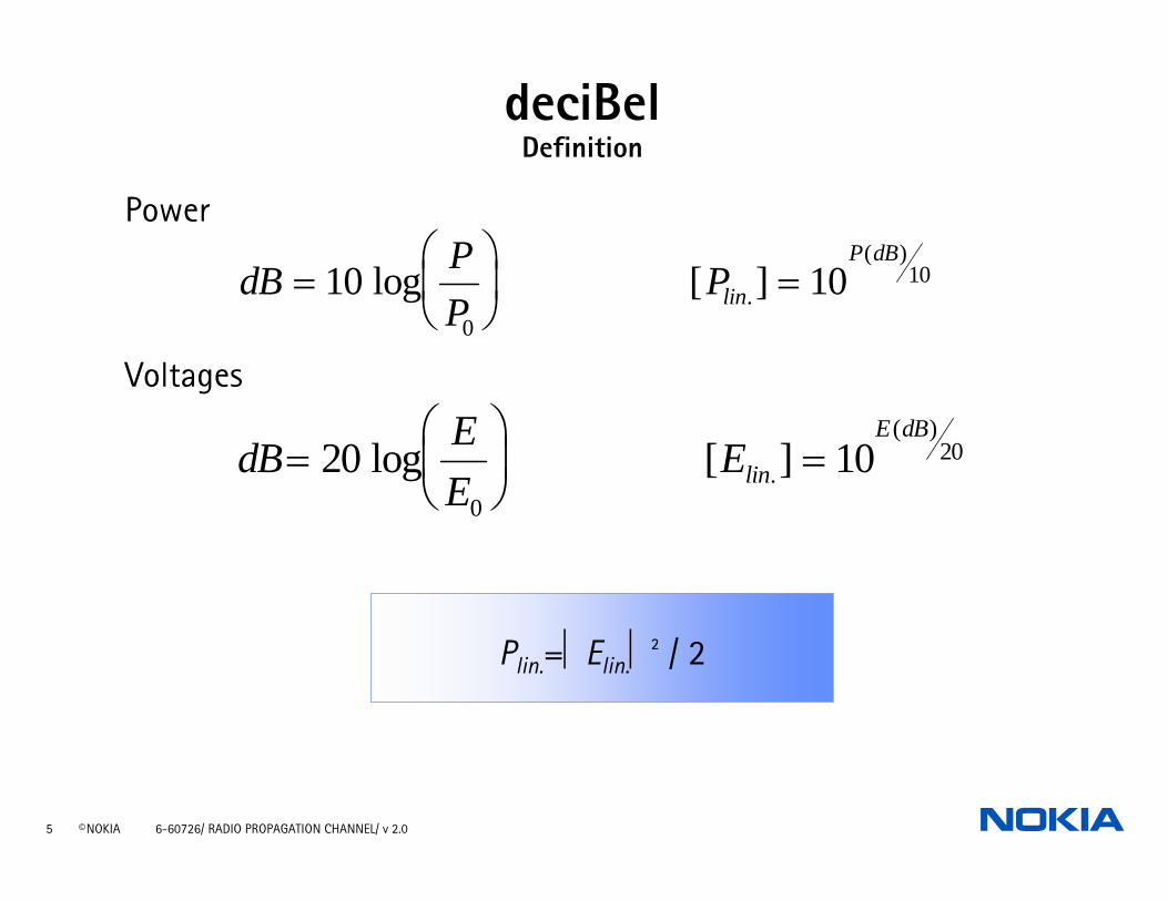
deciBelDefinition
Power
Voltages
dB PP
Plin
P dB=
⎛
⎝⎜
⎞
⎠⎟ =10 10
0
10log [ ].( )
dB EE
Elin
E dB=
⎛
⎝⎜
⎞
⎠⎟ =20 10
0
20log [ ].( )
Plin.=⏐Elin.⏐² / 2
6 © NOKIA 6-60726/ RADIO PROPAGATION CHANNEL/ v 2.0
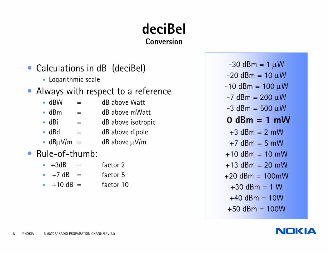
deciBelConversion
• Calculations in dB (deciBel)• Logarithmic scale
• Always with respect to a reference• dBW = dB above Watt• dBm = dB above mWatt• dBi = dB above isotropic• dBd = dB above dipole• dBµV/m = dB above µV/m
• Rule-of-thumb: • +3dB = factor 2• +7 dB = factor 5• +10 dB = factor 10
-30 dBm = 1 µW-20 dBm = 10 µW-10 dBm = 100 µW-7 dBm = 200 µW-3 dBm = 500 µW
0 dBm = 1 mW+3 dBm = 2 mW+7 dBm = 5 mW
+10 dBm = 10 mW+13 dBm = 20 mW+20 dBm = 100mW
+30 dBm = 1 W+40 dBm = 10W+50 dBm = 100W
7 © NOKIA 6-60726/ RADIO PROPAGATION CHANNEL/ v 2.0
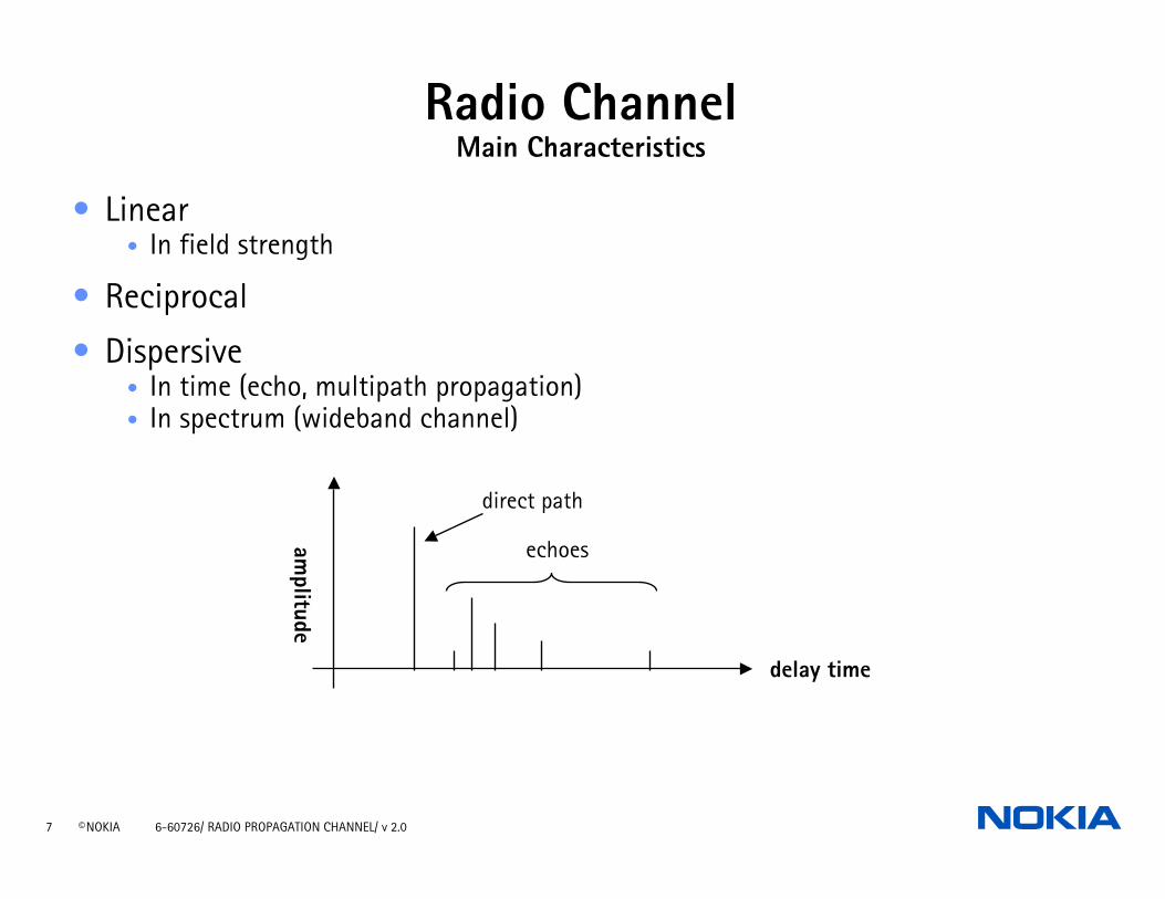
Radio ChannelMain Characteristics
• Linear• In field strength
• Reciprocal
• Dispersive• In time (echo, multipath propagation)• In spectrum (wideband channel)
amplitude
delay time
direct path
echoes
8 © NOKIA 6-60726/ RADIO PROPAGATION CHANNEL/ v 2.0
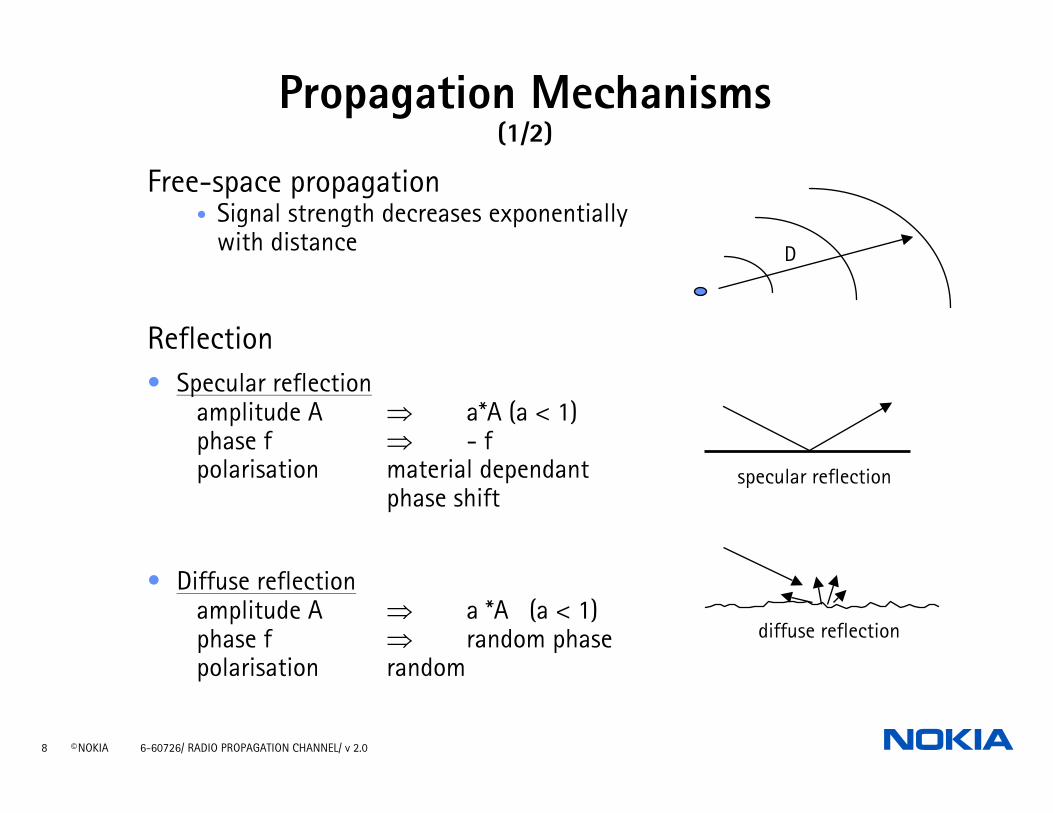
Propagation Mechanisms(1/2)
Free-space propagation• Signal strength decreases exponentially
with distance
Reflection• Specular reflection
amplitude A ⇒ a*A (a < 1)phase f ⇒ - fpolarisation material dependant
phase shift
• Diffuse reflectionamplitude A ⇒ a *A (a < 1)phase f ⇒ random phasepolarisation random
specular reflection
diffuse reflection
D
9 © NOKIA 6-60726/ RADIO PROPAGATION CHANNEL/ v 2.0
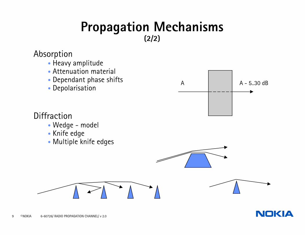
Propagation Mechanisms(2/2)
Absorption• Heavy amplitude• Attenuation material• Dependant phase shifts• Depolarisation
Diffraction• Wedge - model• Knife edge• Multiple knife edges
A A - 5..30 dB
10 © NOKIA 6-60726/ RADIO PROPAGATION CHANNEL/ v 2.0
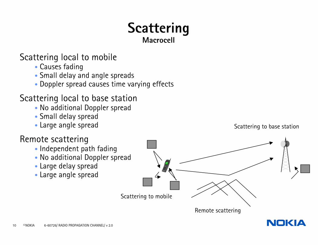
ScatteringMacrocell
Scattering local to mobile• Causes fading • Small delay and angle spreads• Doppler spread causes time varying effects
Scattering local to base station• No additional Doppler spread• Small delay spread• Large angle spread
Remote scattering• Independent path fading• No additional Doppler spread• Large delay spread• Large angle spread
Scattering to mobile
Scattering to base station
Remote scattering

11 © NOKIA 6-60726/ RADIO PROPAGATION CHANNEL/ v 2.0
ScatteringMicrocell
• Many local scatterers: Large angle spread
• Low delay spread
• Medium or high Doppler spread
12 © NOKIA 6-60726/ RADIO PROPAGATION CHANNEL/ v 2.0
Radio Propagation Channel
REFLECTIONS, DIFFRACTIONS AND SCATTERING
MULTIPATH AND FADING
PROPAGATION SLOPE AND DIFFERENT ENVIRONMENTS

13 © NOKIA 6-60726/ RADIO PROPAGATION CHANNEL/ v 2.0
Doppler Spread• A moving source or receiver, the
frequency observed by the receiver will rise if the distance is decreasing or fall if the distance is increasing
• A carrier transmitted on a single frequency will propagate via multiple reflections and each reflection will arrive at the receiver shifted in frequency by a different amount. The difference between the highest shift and the lowest shift will give the Doppler spread.
• Doppler spectrum:
14 © NOKIA 6-60726/ RADIO PROPAGATION CHANNEL/ v 2.0
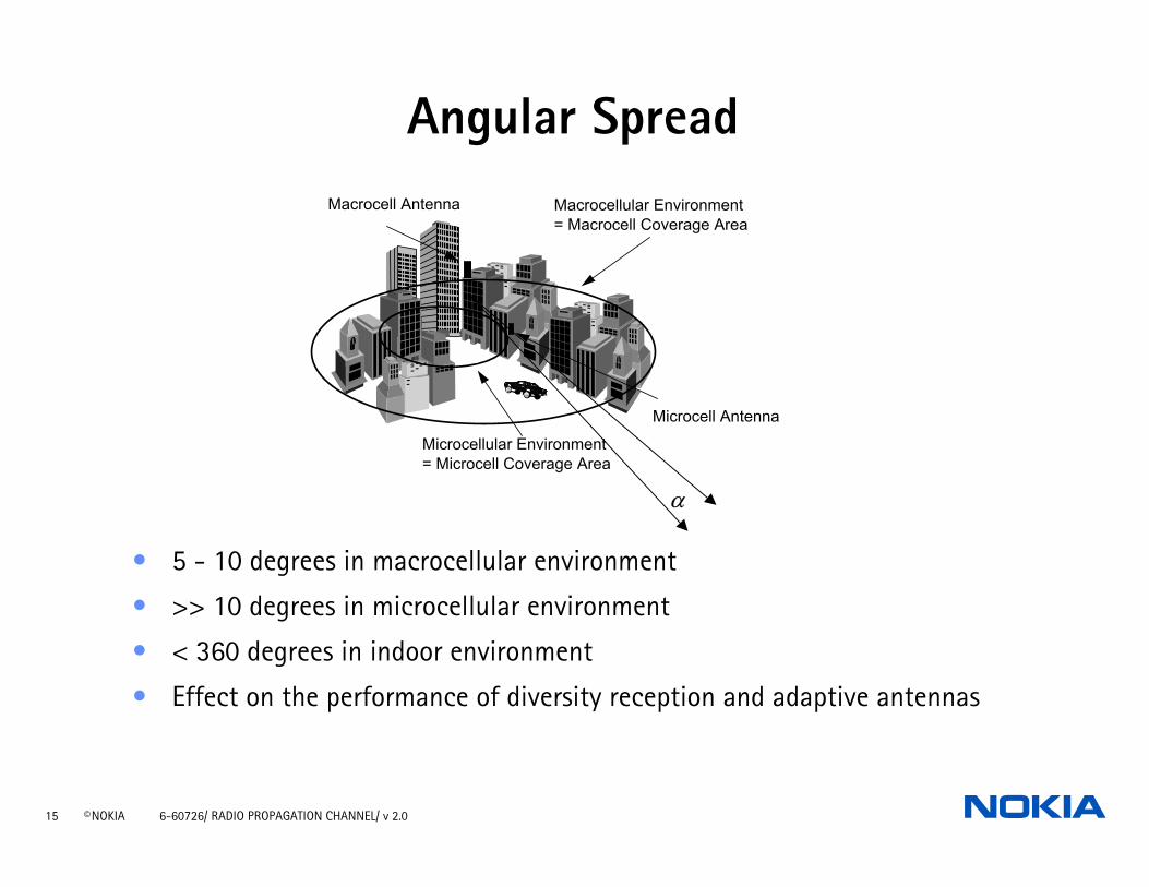
Angular Spread• Angular spread arises due to
multipath, both from local scatterersnear the mobile, near the base station and remote scatterers
• Angular spread is a function of base station location, distance and environment
15 © NOKIA 6-60726/ RADIO PROPAGATION CHANNEL/ v 2.0
Macrocellular Environment= Macrocell Coverage Area
Microcellular Environment= Microcell Coverage Area
Microcell Antenna
Macrocell Antenna
α
Angular Spread
• 5 - 10 degrees in macrocellular environment
• >> 10 degrees in microcellular environment
• < 360 degrees in indoor environment
• Effect on the performance of diversity reception and adaptive antennas
16 © NOKIA 6-60726/ RADIO PROPAGATION CHANNEL/ v 2.0
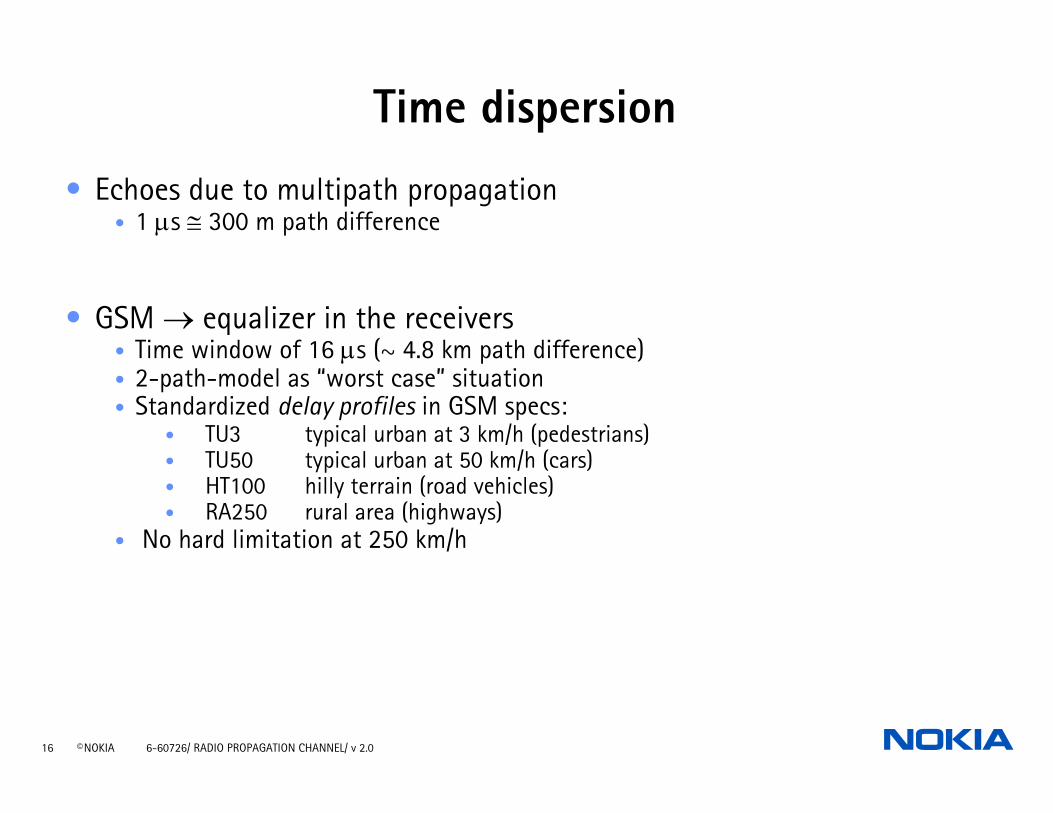
Time dispersion
• Echoes due to multipath propagation• 1 µs ≅ 300 m path difference
• GSM → equalizer in the receivers• Time window of 16 µs (~ 4.8 km path difference)• 2-path-model as “worst case” situation• Standardized delay profiles in GSM specs:
• TU3 typical urban at 3 km/h (pedestrians)• TU50 typical urban at 50 km/h (cars)• HT100 hilly terrain (road vehicles)• RA250 rural area (highways)
• No hard limitation at 250 km/h
17 © NOKIA 6-60726/ RADIO PROPAGATION CHANNEL/ v 2.0
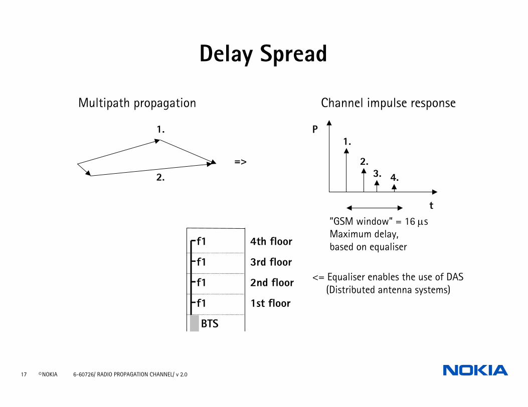
t
P
4.3.2.
1.
”GSM window” = 16 µsMaximum delay,based on equaliser
1.
2.=>
f1
f1
f1
f1
BTS
1st floor
2nd floor
3rd floor
4th floor
Delay Spread
Multipath propagation Channel impulse response
<= Equaliser enables the use of DAS (Distributed antenna systems)
18 © NOKIA 6-60726/ RADIO PROPAGATION CHANNEL/ v 2.0
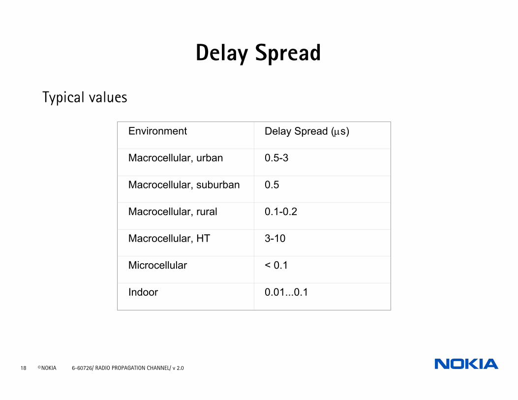
Delay Spread
Typical values
Environment Delay Spread (µs)
Macrocellular, urban 0.5-3
Macrocellular, suburban 0.5
Macrocellular, rural 0.1-0.2
Macrocellular, HT 3-10
Microcellular < 0.1
Indoor 0.01...0.1
19 © NOKIA 6-60726/ RADIO PROPAGATION CHANNEL/ v 2.0
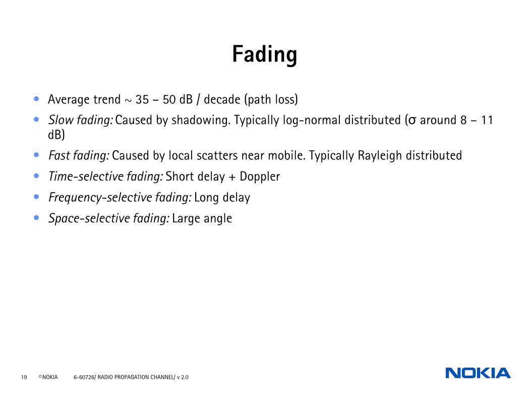
Fading
• Average trend ~ 35 – 50 dB / decade (path loss)
• Slow fading: Caused by shadowing. Typically log-normal distributed (σ around 8 – 11 dB)
• Fast fading: Caused by local scatters near mobile. Typically Rayleigh distributed
• Time-selective fading: Short delay + Doppler
• Frequency-selective fading: Long delay
• Space-selective fading: Large angle
20 © NOKIA 6-60726/ RADIO PROPAGATION CHANNEL/ v 2.0
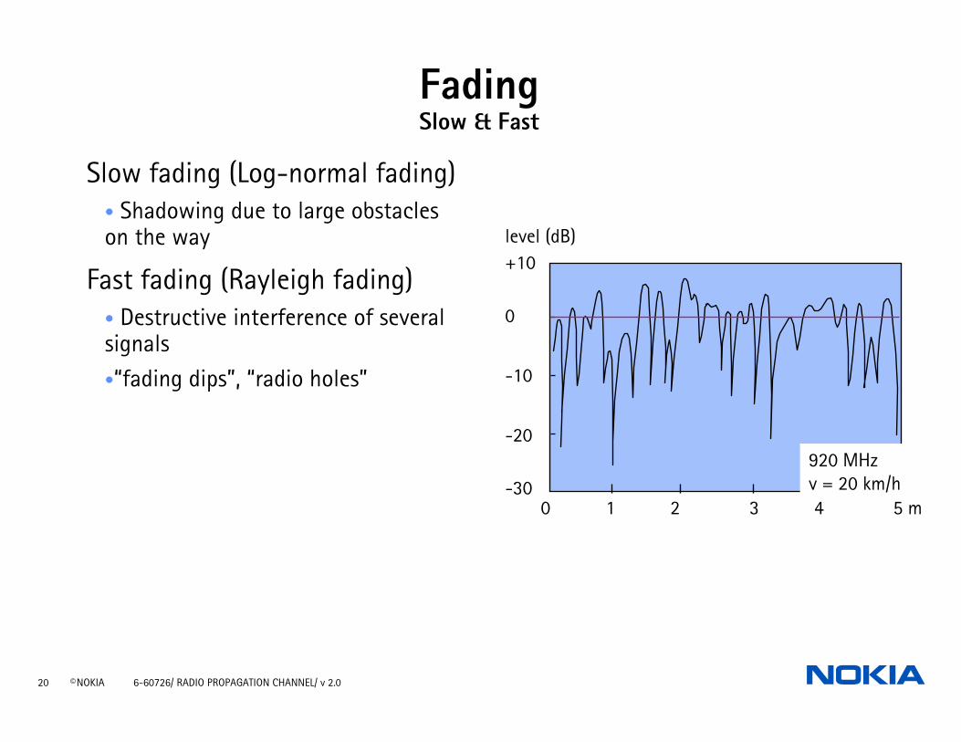
FadingSlow & Fast
Slow fading (Log-normal fading)• Shadowing due to large obstacles on the way
Fast fading (Rayleigh fading)• Destructive interference of several signals•“fading dips”, “radio holes”
+10
0
-10
-20
-300 1 2 3 4 5 m
level (dB)
920 MHzv = 20 km/h
21 © NOKIA 6-60726/ RADIO PROPAGATION CHANNEL/ v 2.0
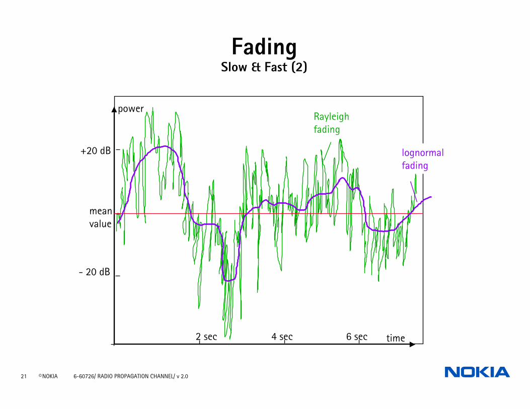
time
power
2 sec 4 sec 6 sec
+20 dB
mean value
- 20 dB
lognormal fading
Rayleighfading
FadingSlow & Fast (2)
22 © NOKIA 6-60726/ RADIO PROPAGATION CHANNEL/ v 2.0
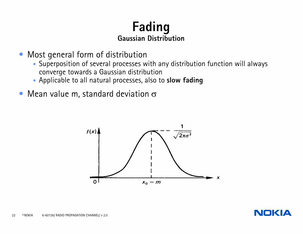
FadingGaussian Distribution
• Most general form of distribution• Superposition of several processes with any distribution function will always
converge towards a Gaussian distribution• Applicable to all natural processes, also to slow fading
• Mean value m, standard deviation σ

23 © NOKIA 6-60726/ RADIO PROPAGATION CHANNEL/ v 2.0
• Applicable to fast fading in obstructed paths
p r r r( ) exp( )= −σ σ2
2
22
FadingRayleigh Distribution
24 © NOKIA 6-60726/ RADIO PROPAGATION CHANNEL/ v 2.0
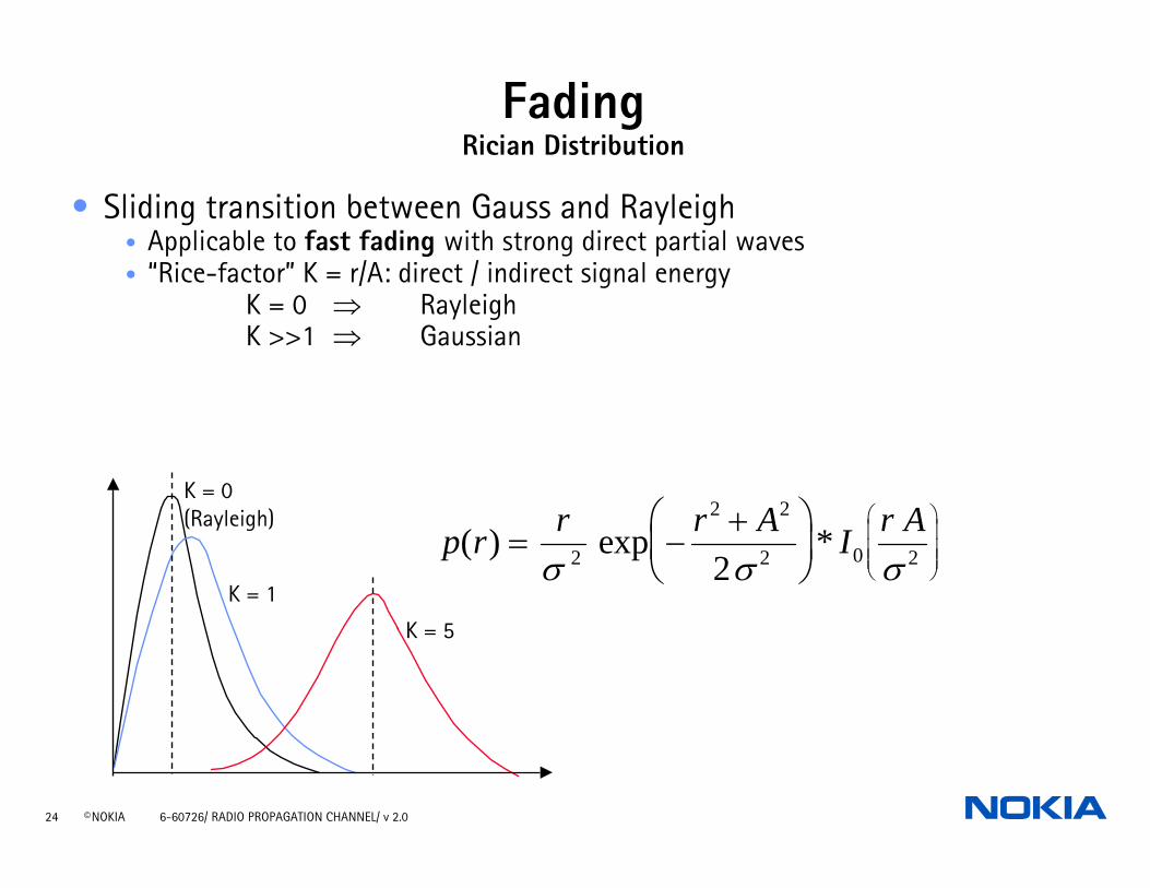
• Sliding transition between Gauss and Rayleigh• Applicable to fast fading with strong direct partial waves• “Rice-factor” K = r/A: direct / indirect signal energy
K = 0 ⇒ RayleighK >>1 ⇒ Gaussian
p r r r A I r A( ) exp *= −+⎛
⎝⎜
⎞⎠⎟
⎛
⎝
⎜⎜⎜
⎞
⎠
⎟⎟⎟σ σ σ2
2 2
2 0 22
K = 0(Rayleigh)
K = 1
K = 5
FadingRician Distribution
25 © NOKIA 6-60726/ RADIO PROPAGATION CHANNEL/ v 2.0
Radio Propagation Channel
REFLECTIONS, DIFFRACTIONS AND SCATTERING
MULTIPATH AND FADING
PROPAGATION SLOPE AND DIFFERENT ENVIRONMENTS
26 © NOKIA 6-60726/ RADIO PROPAGATION CHANNEL/ v 2.0
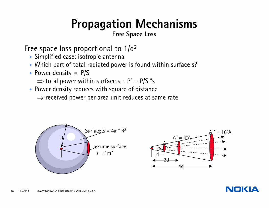
Propagation MechanismsFree Space Loss
Free space loss proportional to 1/d2
• Simplified case: isotropic antenna• Which part of total radiated power is found within surface s?• Power density = P/S
⇒ total power within surface s : P´ = P/S *s • Power density reduces with square of distance
⇒ received power per area unit reduces at same rate
RSurface S = 4π * R2
assume surfaces = 1m2
2d4d
A´ = 4*AA´´ = 16*A
A
d
27 © NOKIA 6-60726/ RADIO PROPAGATION CHANNEL/ v 2.0
2
4⎟⎠⎞
⎜⎝⎛
πλ
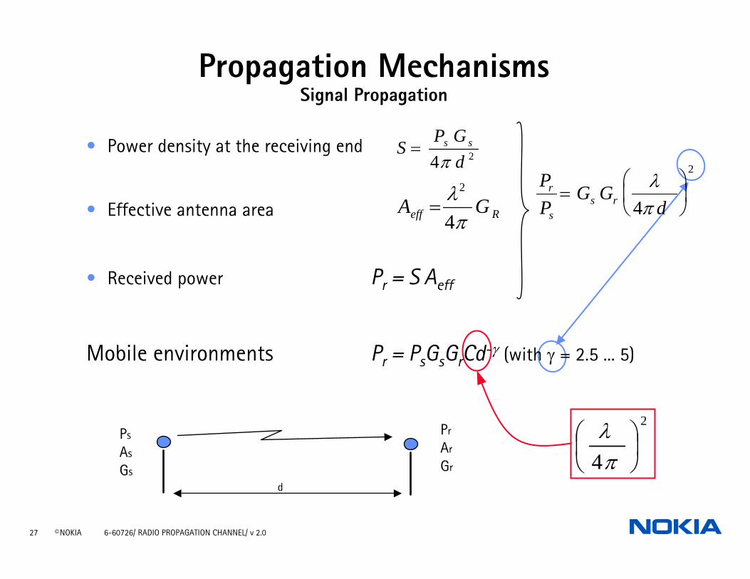
• Power density at the receiving end
• Effective antenna area
• Received power Pr = S Aeff
Mobile environments Pr = PsGsGrCd-γ (with γ = 2.5 ... 5)
Reff GAπλ4
2
=
SP G
ds s=
4 2πPP
G Gd
r
ss r=
⎛
⎝⎜
⎞
⎠⎟
λπ4
2
Ps
As
Gs
Pr
Ar
Gr
d
Propagation MechanismsSignal Propagation
28 © NOKIA 6-60726/ RADIO PROPAGATION CHANNEL/ v 2.0
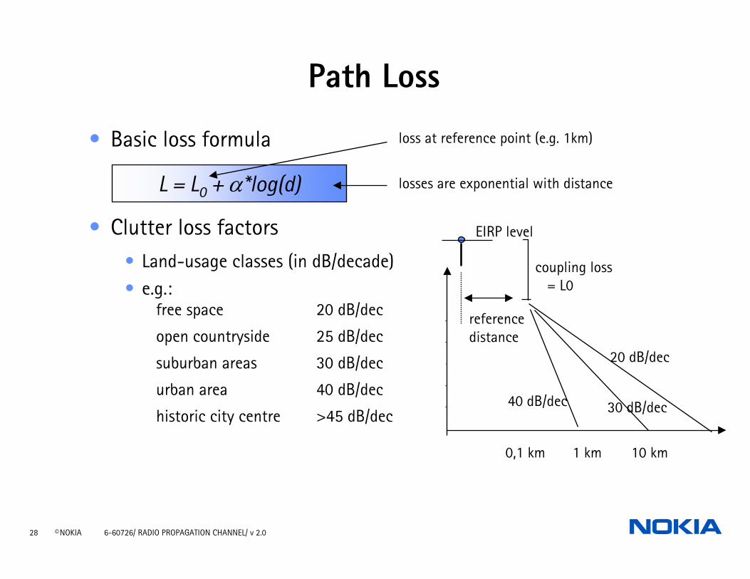
• Basic loss formula
• Clutter loss factors• Land-usage classes (in dB/decade)• e.g.:
free space 20 dB/dec
open countryside 25 dB/dec
suburban areas 30 dB/dec
urban area 40 dB/dec
historic city centre >45 dB/dec
L = L0 + α*log(d)
loss at reference point (e.g. 1km)
losses are exponential with distance
0,1 km 10 km1 km
EIRP level
coupling loss= L0
referencedistance
20 dB/dec
30 dB/dec40 dB/dec
Path Loss
29 © NOKIA 6-60726/ RADIO PROPAGATION CHANNEL/ v 2.0
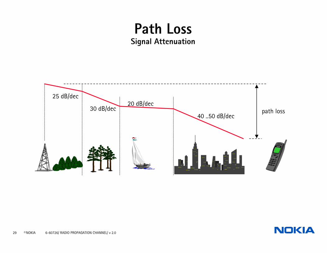
Path LossSignal Attenuation
25 dB/dec
30 dB/dec20 dB/dec
40 ..50 dB/decpath loss
30 © NOKIA 6-60726/ RADIO PROPAGATION CHANNEL/ v 2.0
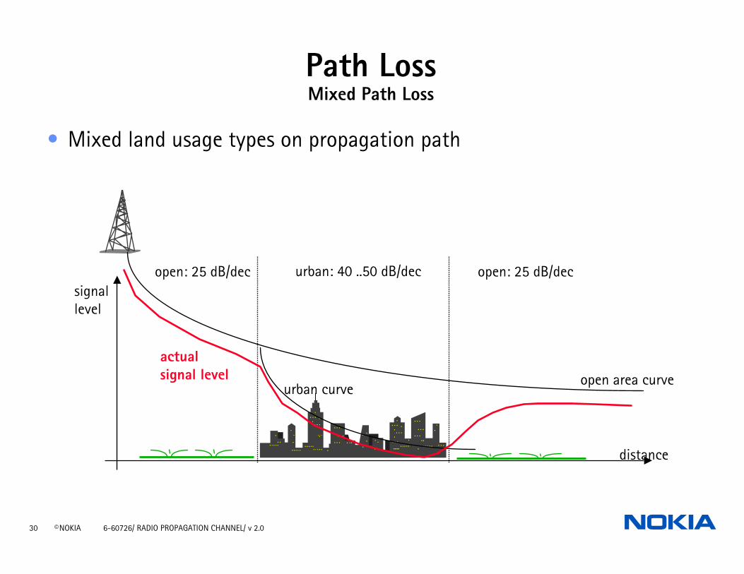
Path LossMixed Path Loss
urban: 40 ..50 dB/decopen: 25 dB/dec open: 25 dB/dec
open area curveurban curve
actual signal level
signallevel
distance
• Mixed land usage types on propagation path
31 © NOKIA 6-60726/ RADIO PROPAGATION CHANNEL/ v 2.0
Exercises / Questions
Why is an equalizer needed in GSM terminal?
Explain the difference between slow and fast fading!
32 © NOKIA 6-60726/ RADIO PROPAGATION CHANNEL/ v 2.0
References
1. ETSI, Digital cellular telecommunications system (Phase 2+), Mobile radio interface layer 3 specification, GSM 04.08
2. D. Parsons, “The Mobile Radio Propagation Channel,” Pentech Press, 1992.
3. W.C. Jakes, Jr., (ed.), “Microwave Mobile Communications,” Wiley-Interscience, 1974
4. W.C.Y. Lee, “Mobile Communications Design Fundamentals,” John Wiley & Sons, 1993.
5. W.C.Y. Lee, “Mobile Cellular Telecommunication Systems,” McGraw-Hill Book Company, 1990
6. S. Saunders, “Antennas and Propagation for Wireless Communication Systems,” John Wiley & Sons, 1999.
7. J. Lempiäinen, M. Manninen, ”Radio Interface System Planningfor GSM/GPRS/UMTS,” Kluwer Academic Publishers 2001.