explanatory document to all tsos’ proposal for the … · in addition to a public consultation of...
TRANSCRIPT

ENTSO-E AISBL • Avenue de Cortenbergh 100 • 1000 Brussels • Belgium • Tel + 32 2 741 09 50 • Fax + 32 2 741 09 51 • [email protected] • www. entsoe.eu
Explanatory Document to All TSOs’ proposal for the implementation framework for a European
platform for the imbalance netting process in accordance with Article 22 of Commission Regulation
(EU) 2017/2195 of 23 November 2017 establishing a guideline on electricity balancing
Explanatory Document to All TSOs’ proposal for the implementation framework for a European platform for the imbalance netting process in
accordance with Article 22 of Commission Regulation (EU) 2017/2195 of 23 November 2017 establishing a guideline on electricity balancing
18 June 2018
DISCLAIMER This document is submitted by all transmission system operators (TSOs) to all NRAs for information purposes only accompanying the ‘All TSOs’ proposal for the implementation framework for a European platform for the imbalance netting process in accordance with Article 22 of Commission Regulation (EU) 2017/2195 of 23 November 2017 establishing a guideline on electricity balancing’.

1
ENTSO-E AISBL • Avenue de Cortenbergh 100 • 1000 Brussels • Belgium • Tel + 32 2 741 09 50 • Fax + 32 2 741 09 51 • [email protected] • www. entsoe.eu
Explanatory Document to All TSOs’ proposal for the implementation framework for a European
platform for the imbalance netting process in accordance with Article 22 of Commission Regulation
(EU) 2017/2195 of 23 November 2017 establishing a guideline on electricity balancing
Contents 1 Introduction ..............................................................................................................................................2
1.1 Content of this document..................................................................................................................2
2 Implementation of the IN-Platform ..........................................................................................................2
3 Functions of the IN-Platform ....................................................................................................................3
3.1 Imbalance netting process function ..................................................................................................3
3.2 TSO-TSO settlement function ..........................................................................................................3
4 Member TSOs, participating TSOs, cost sharing and decision-making ...................................................4
5 Framework for harmonisation of the terms and conditions related to balancing......................................5
6 Description of the algorithm for the operation of imbalance netting process function ............................5
6.1 Interaction between the aFRR-Platform and the IN-PlatformIN-Platform ......................................6
6.2 Congestion management ..................................................................................................................6
6.3 Examples for the calculation of the imbalance netting algorithm ....................................................8
6.4 Optimisation regions ......................................................................................................................15
7 Publication of information and reporting ...............................................................................................18
Figures
Figure 1. Indicative accession timeline for future IGCC operational members ...............................................3 Figure 2: Example LFC structure configuration for participating synchronous areas .....................................7 Figure 3. Example without consideration of restrictions ..................................................................................9 Figure 4. One limitation (not Active) .............................................................................................................10 Figure 5. Example with one active limitation (1st example) ..........................................................................10 Figure 6. One Active limitation (2nd example) ..............................................................................................11 Figure 7. One active limitation without an impact on correction values ........................................................11 Figure 8. One active profile limitation ...........................................................................................................12 Figure 9. Combination of one active profile limit with other limits ...............................................................12 Figure 10. Active profile limitations and active limitations ...........................................................................13 Figure 11. Example for "triangle" configuration (active limitation) ..............................................................13 Figure 12. Example for "triangle" configuration (Active limitation and profile limitation) ..........................14 Figure 13. Example for "triangle" configuration (active profile limitation)...................................................14 Figure 14. Example of an optimisation region with prior access to concerned borders .................................15 Figure 15. Example of two optimisation regions with prior access to concerned borders .............................16 Figure 16. Common merit order list for the aFRR cooperation between LFC blocks B and C .....................16 Figure 17. Example for optimisation regions without limitation ...................................................................17 Figure 18. Example for optimisation regions with limitation ........................................................................18
2
ENTSO-E AISBL • Avenue de Cortenbergh 100 • 1000 Brussels • Belgium • Tel + 32 2 741 09 50 • Fax + 32 2 741 09 51 • [email protected] • www. entsoe.eu
Explanatory Document to All TSOs’ proposal for the implementation framework for a European
platform for the imbalance netting process in accordance with Article 22 of Commission Regulation
(EU) 2017/2195 of 23 November 2017 establishing a guideline on electricity balancing
1 Introduction
This document gives background information and rationale for the all TSOs proposal for the
implementation framework for a European platform for the imbalance netting process (this proposal is
hereafter referred to as the “INIF”), required by Article 22 of Commission Regulation (EU) 2017/2195 of
23 November 2017 establishing a guideline on electricity balancing (hereafter referred to as “EBGL”).
1.1 Content of this document
This document is built up as follows: Chapter 2 contains an explanation of the proposal of entity that will
perform the imbalance netting process function and the proposal of entity that will perform the TSO-TSO
settlement function. Chapter 3 includes the explanation of Article 9 of the INIF. Chapter 4 provides
explanations and examples on the terms ‘member TSO’, ‘participating TSO’ and the cost sharing. Chapter
6 provides the detailed description of the algorithm for the operation of imbalance netting process function
with the examples of calculations, particularly examples for unrestricted optimisation (without limits),
optimisation with limits and for application of optimisation regions.
2 Implementation of the IN-Platform
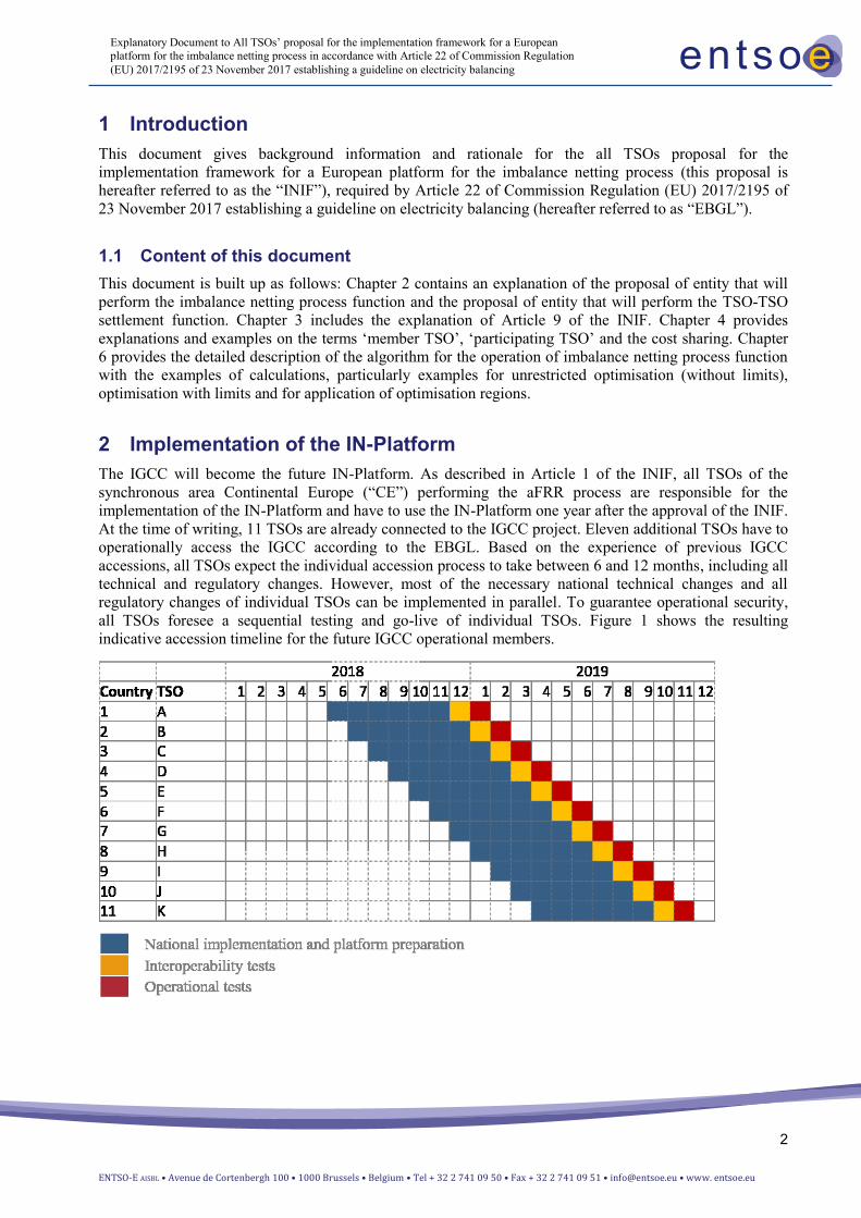
The IGCC will become the future IN-Platform. As described in Article 1 of the INIF, all TSOs of the
synchronous area Continental Europe (“CE”) performing the aFRR process are responsible for the
implementation of the IN-Platform and have to use the IN-Platform one year after the approval of the INIF.
At the time of writing, 11 TSOs are already connected to the IGCC project. Eleven additional TSOs have to
operationally access the IGCC according to the EBGL. Based on the experience of previous IGCC
accessions, all TSOs expect the individual accession process to take between 6 and 12 months, including all
technical and regulatory changes. However, most of the necessary national technical changes and all
regulatory changes of individual TSOs can be implemented in parallel. To guarantee operational security,
all TSOs foresee a sequential testing and go-live of individual TSOs. Figure 1 shows the resulting
indicative accession timeline for the future IGCC operational members.

3
ENTSO-E AISBL • Avenue de Cortenbergh 100 • 1000 Brussels • Belgium • Tel + 32 2 741 09 50 • Fax + 32 2 741 09 51 • [email protected] • www. entsoe.eu
Explanatory Document to All TSOs’ proposal for the implementation framework for a European
platform for the imbalance netting process in accordance with Article 22 of Commission Regulation
(EU) 2017/2195 of 23 November 2017 establishing a guideline on electricity balancing
Figure 1. Indicative accession timeline for future IN-Platform participating TSOs
In addition to a public consultation of any modifications to the INIF, stakeholders will be informed of the
updates related to the IN-Platform through the IGCC website1.
3 Functions of the IN-Platform
3.1 Imbalance netting process function
During the development of the INIF, the following options were examined by all TSOs for the designation
of any entity entrusted with operating the imbalance netting process function:
(a) Appointing one or more TSOs to operate the imbalance netting process function on behalf of all
TSOs;
(b) Creating a new entity to operate the imbalance netting process function as a vehicle of cooperation
among TSOs and on their behalf;
(c) Designating an existing entity to operate the imbalance netting process function as a vehicle of
cooperation among TSOs and on their behalf;
(d) Appointing the development and operation of the imbalance netting process function to a third
party independent from the TSOs.
Having considered the above options, all TSOs conclude that appointing a real-time entity, which is one EU
TSO or an entity formed by EU TSOs, to operate the imbalance netting process function is the most
efficient and pragmatic approach. Currently, a EU TSO operates the IGCC, which is the implementation
project which will serve as basis for development of the IN-Platform as agreed by all TSOs due to
following reasons:
(a) The imbalance netting process function of IGCC is already implemented and operates the
imbalance netting process of 11 TSOs; by this, implementation costs can be avoided;
(b) IGCC is in operation since 2010 – the entity currently operating the IGCC and the TSOs have
gained a vast operational experience in operation of the imbalance netting process with an
availability higher than 99.9 % of time;
(c) Due to the impact on operational security, implementation of real-time processes and their
coordination must be allocated within the infrastructure of the TSOs and fulfil the respective
infrastructure security and reliability requirements;
(d) A close interaction with other real-time operational processes is ensured.
3.2 TSO-TSO settlement function
When developing the INIF, the following options were examined by all TSOs for the designation of any
entity entrusted with operating the TSO-TSO settlement function:
(a) Appointing one or more TSOs to operate the TSO-TSO settlement function on behalf of all TSOs;
1 https://www.entsoe.eu/network_codes/eb/imbalance-netting/

4
ENTSO-E AISBL • Avenue de Cortenbergh 100 • 1000 Brussels • Belgium • Tel + 32 2 741 09 50 • Fax + 32 2 741 09 51 • [email protected] • www. entsoe.eu
Explanatory Document to All TSOs’ proposal for the implementation framework for a European
platform for the imbalance netting process in accordance with Article 22 of Commission Regulation
(EU) 2017/2195 of 23 November 2017 establishing a guideline on electricity balancing
(b) Creating a new entity to operate the TSO-TSO settlement function among TSOs and on their
behalf;
(c) Designating an existing entity to operate the TSO-TSO settlement function among TSOs and on
their behalf;
(d) Appointing the development and operation of the TSO-TSO settlement function to a third party
independent from the TSOs.
Having considered the above options, all TSOs conclude that appointing an settlement entity for imbalance
netting, which is a EU TSO or an entity formed by EU TSOs, to operate the TSO-TSO settlement function
among TSOs and on their behalf is the most efficient and pragmatic approach. Currently, a EU TSO
operates the IGCC, which is the implementation project which will serve as basis for development of the
IN-Platform as agreed by all TSOs, due to following reasons:
(a) The proposed TSO-TSO settlement function is already implemented in the IGCC and operates the
TSO-TSO settlement of 11 TSOs; by this, implementation costs can be avoided. TSO-TSO
settlement will be subject to an all-TSO approval of the proposal according to Article 50(1)(d);
(b) IGCC is in operation since 2010 – the entity currently operating the IGCC and the TSOs have
gained a vast operational experience in operation of the TSO-TSO settlement function;
(c) Data availability and coordination at the host-level of the entity currently operating the IGCC is
more efficient than a decentralised solution at individual TSOs;
(d) One centralised solution for all balancing products is not seen as beneficial at this point of time.
This solution will be revised within the ENTSO-E framework when the market design and
settlement characteristics of other European balancing platforms is more advanced.
The entity currently operating the IGCC is TransnetBW. IGCC was appointed by ENTSO-E as the
implementation project for the IN-Platform on 11 February 2016.
Further information about the settlement process used in IGCC at the time of writing can be found in
Chapter 6 ‘Settlement Principles’ of the ‘Stakeholder document for the principles of IGCC’ located in the
ENTSO-E website2. The proposals pursuant Article 30(3), Article 50(1)(d) and Article 52(2) of the EBGL
are out of scope of the INIF.
4 Member TSOs, participating TSOs, cost sharing and decision-
making
As explained in the Article 1 of the INIF, the use of the IN-Platform is compulsory for all TSOs of the
Continental Europe synchronous area performing the automatic frequency restoration process. The deadline
for implementing and making operational of the IN-Platform is one year after the approval of the INIF.
Finally, the deadline for the TSOs in Contintental Europe to use the IN-Platform is also one year after the
approval of the INIF (subject to derogation of national regulatory authority).
Member TSOs are those TSOs that have joined the IN-Platform. These TSOs participate in the decision-
making of the Steering Committee of the platform and are responsible to implement and comply with the
2
https://www.entsoe.eu/Documents/Network%20codes%20documents/Implementation/IGCC/20161020_IGCC_Stakeh
older_document.pdf

5
ENTSO-E AISBL • Avenue de Cortenbergh 100 • 1000 Brussels • Belgium • Tel + 32 2 741 09 50 • Fax + 32 2 741 09 51 • [email protected] • www. entsoe.eu
Explanatory Document to All TSOs’ proposal for the implementation framework for a European
platform for the imbalance netting process in accordance with Article 22 of Commission Regulation
(EU) 2017/2195 of 23 November 2017 establishing a guideline on electricity balancing
decisions made. The TSOs that have the obligation to use the IN-Platform have to become member TSOs
by one year after the approval of the INIF.
Participating TSOs are member TSOs that use the IN-Platform for intended exchange of energy, i.e.: they
are a subset of member TSOs. The target is that all member TSOs will become participating TSOs by one
year after approval of INIF at the latest, subject to national derogation. The only exception would be when
an LFC area consists of more than one monitoring area. In such case, only the TSO appointed in the LFC
area operational agreement as responsible for the implementation and operation of the automatic frequency
restoration process according to Article 143(4) of the SOGL shall use the IN-Platform, i.e.: become a
participating TSO. The reason to differentiate between member TSOs and participating TSOs is the
following:
(a) The IGCC project may fulfil the requirements according to the INIF earlier than the deadline of one
year after the approval of the INIF, which means that the IN-Platform will be operational before
that deadline. Therefore, some member TSOs may become participating TSOs before the deadline
to use the IN-Platform, i.e.: one year after approval of the INIF.
(b) If necessary, a member TSO may apply for a derogation from using the IN-Platform by one year
after the approval of INIF. Therefore, a member TSO can become a participating TSOs later than
the deadline of one year after approval of INIF, according to granted derogation.
Member TSOs are bearing the common costs of establishing and amending the platform according to
Article 10(4) and 10(8) of the INIF. However, any common operational costs according to Article 10(5) and
10(9) of the INIF are being borne only by the participating TSOs since these are using the IN-Platform
operationally.
In order to implement and operate the IN-Platform, the member TSOs are required to make decisions
through the Steering Committee on a wide variety of topics. In doing so, TSOs will aim for unanimity and
will focus on good communication and processes to facilitate that aim. However, in case unanimity shows
to be unfeasible (for example, due to conflicting local needs), qualified majority voting will be used. The
qualified majority voting principles are modelled after those given in EBGL, although voting is done by
member TSOs. This includes member TSOs who are not yet participating TSOs.
In case of a vote, a quorum of at least the majority (50 % + 1) of the member TSOs involved in the vote is
required. Requiring a quorum ensures that each party is aware of the voting process and that the
argumentation of all parties can be taken into account in a proper way in the decision process.
5 Framework for harmonisation of the terms and conditions related to
balancing
The imbalance netting process is the process that aims to minimise the amount of activated aFRR, by
avoiding their simultaneous counteractivation. The process does not require any activation of standard
neither specific products for balancing energy. Moreover, in accordance with the Article 1 of the INIF,
common settlement rules for the TSO-TSO settlement will be proposed and defined pursuant to Article 50
of the EBGL. Thus, all TSOs consider that there is no need for harmonisation of terms and conditions
related to balancing for the establishment of the IN-Platform.
6 Description of the algorithm for the operation of imbalance netting
process function
The optimisation algorithm is part of the imbalance netting process function operated by the real-time
entity. The imbalance netting process function calculates the corrections in real-time for each LFC area,
resulting in imbalance netting. This chapter describes the basic principles of the optimisation calculation.

6
ENTSO-E AISBL • Avenue de Cortenbergh 100 • 1000 Brussels • Belgium • Tel + 32 2 741 09 50 • Fax + 32 2 741 09 51 • [email protected] • www. entsoe.eu
Explanatory Document to All TSOs’ proposal for the implementation framework for a European
platform for the imbalance netting process in accordance with Article 22 of Commission Regulation
(EU) 2017/2195 of 23 November 2017 establishing a guideline on electricity balancing
In order to ensure that there are fall-back solutions in place, on the one hand, the imbalance netting process
function is implemented in two different locations and has at each location a back-up system in operation.
Furthermore, real-time communication between the platform and the participating TSOs is implemented via
two redundant communication lines. As a result of these, there is four-time redundancy in the entire system
for the sake of avoiding any failure in the operation of IN-Platform.
Further information about the imbalance netting process function can be found in chapter 3 “IGCC
Algorithm – Description of the optimisation” of the “Stakeholder document for the principles of IGCC”
located in the ENTSO-E website3.
6.1 Interaction between the aFRR-Platform and the IN-Platform
It is foreseen that the aFRR-Platform implements an implicit imbalance netting process. Hence, in case the
geographical region of the IN-Platform is part of the geographical region of the aFRR-Platform, a separate
algorithm for the IN-Platform will no longer be necessary. By this, the number of entities and the
operational effort would decrease while maintaining the same level of economic efficiency, which could
increase the overall efficiency of the balancing platforms for imbalance netting and aFRR.
During the transition period, while the geographical regions are not the same (e.g.: due to derogations), the
consistent usage of available CZC for the IN-Platform and the aFRR-Platform at the same time has to be
ensured. A calculation of both processes in one activation optimisation function guarantees this necessary
consistency. All TSOs foresee to include both (IN and aFRR) processes in the AOF of the aFRR-Platform.
From an efficiency point of view, an early merging of both platforms would be beneficial. Therefore, the
TSOs recommend NRAs to enable and incentivise the geographical regions of the participating TSOs in the
aFRR-Platform to be at least the same as the geographical regions of the participating TSOs in the IN-
Platform.
FCR is not considered as it is out of scope of the EBGL.
6.2 Congestion management
The available cross-zonal capacity is calculated in accordance with Article 37 of the EBGL. Initially, there
will not be any harmonized recalculation of cross-zonal capacity after intraday markets. Recalculation of
the CZC for balancing is outside the scope of the INIF and will be done at a later stage on a capacity
calculation region level, in accordance with Article 37(3) of the EBGL which requires a common
methodology to be defined 5 years after the entry into force of the EBGL. However, Article 36 of the
EBGL provides also the possibility to allocate CZC for the exchange of balancing capacity and sharing of
reserves, that needs to be taken into account in the calculation of available CZC. In case parts of the whole
European intraday market are performed in a flow-based domain, an extraction of available cross-zonal
capacity per bidding zone border will be used, comparable to the process between the market coupling in
the CORE region and the succceeding intraday market. The available cross-zonal capacity used for IN
process will take into account previous balancing processes.
More in detail, the algorithm will consider available cross-zonal capacities defined between LFC areas and
will make sure that the cross-border exchange for imbalance netting from the optimization must not exceed
the cross-zonal capacity remaining after previous balancing processes. In order to respect operational
3
https://www.entsoe.eu/Documents/Network%20codes%20documents/Implementation/IGCC/20161020_IGCC_Stakeh
older_document.pdf

7
ENTSO-E AISBL • Avenue de Cortenbergh 100 • 1000 Brussels • Belgium • Tel + 32 2 741 09 50 • Fax + 32 2 741 09 51 • [email protected] • www. entsoe.eu
Explanatory Document to All TSOs’ proposal for the implementation framework for a European
platform for the imbalance netting process in accordance with Article 22 of Commission Regulation
(EU) 2017/2195 of 23 November 2017 establishing a guideline on electricity balancing
security limitations and handle or avoid congested situations TSOs shall also be able to limit the available
CZC. The algorithm is then required to take these manual limitations into account in the optimisation result.
Bidding zone borders inside an LFC area and the respective cross-zonal capacity limitations shall not be
explicitly considered by the optimisation algorithm, for the reasons that the aFRR demand is defined and
located per LFC area and it is not possible to calculate the inner-bidding zone cross-border flows in such a
case.
If a border between LFC areas or LFC blocks does not match with a border between bidding zones
according to CACM, the available cross-zonal capacity on this border is considered infinite in default mode
or equal to the respective IT platform technical limit. The current idea is that the technical IT limitations are
designed to implement a plausibility check on the CZC that are used as input by the AOF. The goal is to
prevent that CZCs that are manifestly erroneous (due to IT or communication errors for instance) are used
as such by the algorithm. Any value send as input would be capped to a certain value. However, this value
should not be limitative with respect to any realistic physical follows that could happen on this border.
Typically, the maximum physical capacity of the border could be used to cap the CZC sent. As the borders
have a very different physical capacities and different nature, it is seen as more efficient to define a border
specific plausibility check instead of a single IT technical limitation for all borders. The TSO will agree on
the more detailed values in such a way that the values are not limitative for the market.
Following figure illustrates potential configuration cases:
Figure 2: Example LFC structure configuration for participating synchronous areas
The cases are the following:
A. A bidding zone can consist of one LFC block which consists of one LFC area (e.g. France);
B. A bidding zone can consist of one LFC block with more than one LFC areas (Germany after the
bidding zone split);
C. A bidding zone can consist of more than one LFC block and each of the LFC block can have more
than one LFC areas (bidding zone of Germany and Austria before the bidding zone split);
D. A LFC block can consist of one LFC area which includes more than one bidding zone (Italy,
current NORDIC configuration);

8
ENTSO-E AISBL • Avenue de Cortenbergh 100 • 1000 Brussels • Belgium • Tel + 32 2 741 09 50 • Fax + 32 2 741 09 51 • [email protected] • www. entsoe.eu
Explanatory Document to All TSOs’ proposal for the implementation framework for a European
platform for the imbalance netting process in accordance with Article 22 of Commission Regulation
(EU) 2017/2195 of 23 November 2017 establishing a guideline on electricity balancing
E. A LFC block consists of more than one LFC area where each LFC area equals one bidding zone
(future NORDIC system).
For the illustrated configurations the CZC is initially defined as follows:
1. The CZC between bidding zones (red links) is calculated in accordance with Article 37 of the
EBGL;
2. CZCs within bidding zones (green links) are considered infinite or equal to the respective technical
limitation;
3. CZC between bidding zones within a LFC area (grey links) cannot be considered by the AOF and
are by this considered as infinite in the AOF;
4. If a technical profile on the sum of several borders4 is defined in the intraday market, such limits
will also be taken into account in the AOF.
CZC will be used as the main constraints of the objective function of AOF and in case of congestion
congested areas will be defined with associated impact on cross border marginal prices.
CZC updated values will be provided directly by participating TSOs to IN-Platform in real time on local
control cycle basis.
In case of CZC between TSOs, TSO can choose one of both to send the CZC values in real time. If both
TSOs want to send the CZC values in real time, then minimum value of CZC will be used by AOF.
In downgraded situation, when no other measures are feasible, participating TSOs responsible to send the
CZC will have the possibility to reduce the CZC values manually in real time (requested on his own or by
any affected TSO for operational limitation in accordance with Article 150 of the GL SO), in case of
congestion or constraint link to a CZC border.
6.3 Examples for the calculation of the imbalance netting algorithm
6.3.1 Unrestricted optimisation
Figure 3 demonstrates the calculation of the correction values without limitations. LFC areas A and B are
short (1000 MW in total) while LFC areas C and D are long (500 MW in total).
Therefore, the optimisation targets are to fully net the aFRR demand of C and D and to distribute the
netting for A and B according to the respective shares of the overall positive aFRR demand. Since there are
no limitations, the optimisation target can be reached (the deviation from the optimisation target is zero).
4 Such technical profiles are defined (at least) on the borders out of Poland; from NO2 and NO5 into NO1; and from NO2
and SE3 into DK1

9
ENTSO-E AISBL • Avenue de Cortenbergh 100 • 1000 Brussels • Belgium • Tel + 32 2 741 09 50 • Fax + 32 2 741 09 51 • [email protected] • www. entsoe.eu
Explanatory Document to All TSOs’ proposal for the implementation framework for a European
platform for the imbalance netting process in accordance with Article 22 of Commission Regulation
(EU) 2017/2195 of 23 November 2017 establishing a guideline on electricity balancing
Figure 3. Example without consideration of restrictions
6.3.2 Impact of limitations
In accordance with Article 3(5) of the INIF, limitations to the calculation of the correction value include
available cross-zonal capacity (CZC) calculated in accordance with Article 37 of the EBGL and additional
limitations to the available CZC requested by affected TSOs in accordance with Article 150 of the SOGL.
However, in case two or more TSOs are exchanging balancing capacity, Article 36(2) of the EBGL
provides the possibility to use CZC for the exchange of balancing capacity. If balancing capacity is
exchanged or reserves are shared between two or more TSOs, the allocated capacity needs to be taken into
account in the calculation of available CZC for the imbalance netting process. No other limitations other
than those on the available CZC will apply in normal operation in the IN-Platform. This is different from
the current operation of the IGCC, where some TSOs limit the maximum individual import and export to
their available aFRR volume.
Figure 4 to Figure 13 demonstrate the calculation of the correction value for different scenarios with four
LFC areas.
Figure 4 shows the same scenario as in Figure 3 but with a limitation on the concerned border between B
and C. The exchange in the direction from C to B is limited to 2000 MW (this value could represent the
available CZC or a limitation in accordance with the INIF). The limitation does not affect the correction
value (being higher than the value of 500 MW which is needed to reach the optimisation targets).
IGCC interchange on border
Correction value
100
A
LFC Block X, aFRR-Demand 100
MW
LegendModel
LFC Block A B C D
aFRR-Demand [MW] 200 800 -50 -450
Share of Total Positive Demand [pu] 200/(200+800) = 0.2 800/(200+800) = 0.8 n/a n/a
Share of Total Negative Demand [pu] n/a n/a -50/(-50+(-450) = 0.1 -450/(-50+(-450) = 0.9
Correction - Optimisation Target [MW] -0.2·500 = -100 -0.8·500 = -400 0.1·500 = 50 0.9·500 = 450
Correction Value (Optimisation Result) [MW] -100 -400 50 450
Remaining aFRR-Demand [MW] 200+(-100) = 100 800+(-400) = 400 -50+50 = 0 -450+450 = 0
Deviation from Target [MW] -100-(-100) = 0 -400-(-400) = 0 50-50 = 0 450-450 = 0
Deviation/aFRR-Demand (Absolute Value) [pu] | 0/200 |= 0 | 0/800 | = 0 | 0/50 | = 0 | 0/450 | = 0
+200 +800 -50 -450
Pcorr,A = -100 Pcorr,B = -400 Pcorr,D= 450Pcorr,C = 50
A B C D
100 500 450

10
ENTSO-E AISBL • Avenue de Cortenbergh 100 • 1000 Brussels • Belgium • Tel + 32 2 741 09 50 • Fax + 32 2 741 09 51 • [email protected] • www. entsoe.eu
Explanatory Document to All TSOs’ proposal for the implementation framework for a European
platform for the imbalance netting process in accordance with Article 22 of Commission Regulation
(EU) 2017/2195 of 23 November 2017 establishing a guideline on electricity balancing
Figure 4. One limitation (not Active)
Figure 5 shows the scenario with a more restrictive limit on the concerned border between B and C. The
exchange in the direction from C to B is limited to 100 MW. Therefore, only 100 MW can be exported
from C and D to A and B and the optimisation targets cannot be reached. The impact of the limitations is
distributed according to the shares used for the calculation of the optimisation target, i. e.: A imports a share
of 0.2 of 100 MW and B imports 0.8 of the 100 MW. Accordingly, C exports a share of 0.1 of 100 MW and
D exports a share of 0.9 of 100 MW.
Figure 5. Example with one active limitation (1st example)
Figure 6 moves the limitation of 100 MW to the concerned border between D and C. Now the export of D
is limited to 100 MW. Since the overall amount of short-aFRR demand is 1000 MW, C exports its complete
long aFRR demand of 50 MW. A and B receive the respective shares of the overall export of 150 MW.
IGCC interchange on border
Correction value
100
A
LFC Block X, aFRR-Demand 100
MW
Limits on border
LegendModel
LFC Block A B C D
aFRR-Demand [MW] 200 800 -50 -450
Share of Total Positive Demand [pu] 200/(200+800) = 0.2 800/(200+800) = 0.8 n/a n/a
Share of Total Negative Demand [pu] n/a n/a -50/(-50+(-450) = 0.1 -450/(-50+(-450) = 0.9
Correction - Optimisation Target [MW] -0.2·500 = -100 -0.8·500 = -400 0.1·500 = 50 0.9·500 = 450
Correction Value (Optimisation Result) [MW] -100 -400 50 450
Remaining aFRR-Demand [MW] 200+(-100) = 100 800+(-400) = 400 -50+50 = 0 -450+450 = 0
Deviation from Target [MW] -100-(-100) = 0 -400-(-400) = 0 50-50 = 0 450-450 = 0
Deviation/aFRR-Demand (Absolute Value) [pu] | 0/200 |= 0 | 0/800 | = 0 | 0/(-50) | = 0 | 0/(-450) | = 0
+200 +800 -50 -450
Pcorr,A = -100 Pcorr,B = -400 Pcorr,D= 450Pcorr,C = 50
A B C D
100 500 450
2000
IGCC interchange on border
Correction value
100
A
LFC Block X, aFRR-Demand 100
MW
Limits on border
LegendModel
Active limit
LFC Block A B C D
aFRR-Demand [MW] 200 800 -50 -450
Share of Total Positive Demand [pu] 200/(200+800) = 0.2 800/(200+800) = 0.8 n/a n/a
Share of Total Negative Demand [pu] n/a n/a -50/(-50+(-450) = 0.1 -450/(-50+(-450) = 0.9
Correction - Optimisation Target [MW] -0.2·500 = -100 -0.8·500 = -400 0.1·500 = 50 0.9·500 = 450
Correction Value (Optimisation Result) [MW] -20 -80 10 90
Remaining aFRR-Demand [MW] 200+(-20) = 180 800+(-80) = 720 -50+10 = -40 -450+90 = -360
Deviation from Target [MW] -100-(-20) = -80 -400-(-80) = -320 50-10 = 40 450-90 = 360
Deviation/aFRR-Demand (Absolute Value) [pu] | -80/200 | = 0.4 | -320/800 | = 0.4 | 40/(-50) | = 0.8 | 360/(-450) | = 0.8
+200 +800 -50 -450
Pcorr,A = -20 Pcorr,B = -80 Pcorr,D= 90Pcorr,C = 10
A B C D
20 100 90
100

11
ENTSO-E AISBL • Avenue de Cortenbergh 100 • 1000 Brussels • Belgium • Tel + 32 2 741 09 50 • Fax + 32 2 741 09 51 • [email protected] • www. entsoe.eu
Explanatory Document to All TSOs’ proposal for the implementation framework for a European
platform for the imbalance netting process in accordance with Article 22 of Commission Regulation
(EU) 2017/2195 of 23 November 2017 establishing a guideline on electricity balancing
Figure 6. One Active limitation (2nd example)
Figure 7 introduces an additional concerned border between D and A. Although the limitation between D
and C of 100 MW still exists, the border between D and A can be used to exchange the aditional 350 MW
(no deviation from optimisation target).
Figure 7. One active limitation without an impact on correction values
A profile limitation is a combination of limiting two or more border at the same time and by this a measure
to ensure operational security. Currently applied in IGCC operation, profile limitations will be applicable in
the future operation of the European platform for the imbalance netting process only in case of operational
security, according to Article3(5) of the INIF. Figure 8 shows the example of limitations which affect a sum
of two concerned borders (profile limitations). The sum of the exchange from D to C and from D to A is
limited to zero which means that D cannot export its long imbalance. The impact on A and B is distributed
according to the shares.
IGCC interchange on border
Correction value
100
A
LFC Block X, aFRR-Demand 100
MW
Limits on border
LegendModel
Active limit
LFC Block A B C D
aFRR-Demand [MW] 200 800 -50 -450
Share of Total Positive Demand [pu] 200/(200+800) = 0.2 800/(200+800) = 0.8 n/a n/a
Share of Total Negative Demand [pu] n/a n/a -50/(-50+(-450) = 0.1 -450/(-50+(-450) = 0.9
Correction - Optimisation Target [MW] -0.2·500 = -100 -0.8·500 = -400 0.1·500 = 50 0.9·500 = 450
Correction Value (Optimisation Result) [MW] -30 -120 50 100
Remaining aFRR-Demand [MW] 200+(-30) = 170 800+(-120) = 680 -50+50 = 0 -450+100 = -350
Deviation from Target [MW] -100-(-30) = -70 -400-(-120) = -280 50-50 = 0 450-100 = 350
Deviation/aFRR-Demand (Absolute Value) [pu] | -70/200 | = 0.35 | -280/800 | = 0.35 | 0/(-50) | = 0 | 350/(-450) | = 0.78
+200 +800 -50 -450
Pcorr,A = -30 Pcorr,B = -120 Pcorr,D= 100Pcorr,C = 50
A B C D
30 150
100
100
IGCC interchange on border
Correction value
100
A
LFC Block X, aFRR-Demand 100
MW
Limits on border
LegendModel
Active limit
LFC Block A B C D
aFRR-Demand [MW] 200 800 -50 -450
Share of Total Positive Demand [pu] 200/(200+800) = 0.2 800/(200+800) = 0.8 n/a n/a
Share of Total Negative Demand [pu] n/a n/a -50/(-50+(-450) = 0.1 -450/(-50+(-450) = 0.9
Correction - Optimisation Target [MW] -0.2·500 = -100 -0.8·500 = -400 0.1·500 = 50 0.9·500 = 450
Correction Value (Optimisation Result) [MW] -100 -400 50 450
Remaining aFRR-Demand [MW] 200+(-100) = 100 800+(-400) = 400 -50+50 = 0 -450+450 = 0
Deviation from Target [MW] -100-(-100) = 0 -400-(-400) = 0 50-50 = 0 450-450 = 0
Deviation/aFRR-Demand (Absolute Value) [pu] | 0/200 |= 0 | 0/800 | = 0 | 0/(-50) | = 0 | 0/(-450) | = 0
+200 +800 -50 -450
A B C D
250 150 100
Pcorr,A = -100 Pcorr,B = -400 Pcorr,D= 450Pcorr,C = 50
350
100

12
ENTSO-E AISBL • Avenue de Cortenbergh 100 • 1000 Brussels • Belgium • Tel + 32 2 741 09 50 • Fax + 32 2 741 09 51 • [email protected] • www. entsoe.eu
Explanatory Document to All TSOs’ proposal for the implementation framework for a European
platform for the imbalance netting process in accordance with Article 22 of Commission Regulation
(EU) 2017/2195 of 23 November 2017 establishing a guideline on electricity balancing
Figure 8. One active profile limitation
Figure 9 shows another example of an active profile-limitation. In this case the total import of B is limited
to 100 MW through the restriction of sum of the exchanges from A to B and from C to B. Together with the
maximum import of A, which is limited by the aFRR demand 200 MW, the overall import is limited to 300
MW. The impact is distributed proportionally to C (export of 270 MW) and D (export of 30 MW). Due to
the restriction of the overall import to 300 MW the profile-limitation of D and the limitation from D to C
remain inactive.
Figure 9. Combination of one active profile limit with other limits
Figure 10 introduces a further restriction of total exchange taking the scenario in Figure 9 as starting point.
The CZC from D to A of 0 MW in combination with the CZC of D to C limits the export of D to 100 MW.
Therefore, C and D can export 150 MW in total. Following the principle of proportional distribution B
IGCC interchange on border
Correction value
100
A
LFC Block X, aFRR-Demand 100
MW
Limits on border
(B,A)+(B,C)≤100Limits the sum of the IGCC
interchanges from B to A and B to C
LegendModel
Active limit
LFC Block A B C D
aFRR-Demand [MW] 200 800 -50 -450
Share of Total Positive Demand [pu] 200/(200+800) = 0.2 800/(200+800) = 0.8 n/a n/a
Share of Total Negative Demand [pu] n/a n/a -50/(-50+(-450) = 0.1 -450/(-50+(-450) = 0.9
Correction - Optimisation Target [MW] -0.2·500 = -100 -0.8·500 = -400 0.1·500 = 50 0.9·500 = 450
Correction Value (Optimisation Result) [MW] -200 -100 30 270
Remaining aFRR-Demand [MW] 200+(-200) = 0 800+(-100) = 700 -50+30 = 20 -450+270 = 180
Deviation from Target [MW] -100-(-200) = 100 -400-(-100) = -300 50-30 = 20 450-270 = 180
Deviation/aFRR-Demand (Absolute Value) [pu] | 100/200 | = 0.5 | -300/800 | = 0.375 | 20/(-50) | = 0.4 | 180/(-450) | = 0.4
+200 +800 -50 -450
A B C D
0 100 70
100
(A,B)+(C,B)≤100 (D,C)+(D,A)≤500
Pcorr,A = -200 Pcorr,B = -100 Pcorr,D= 270Pcorr,C = 30
200

13
ENTSO-E AISBL • Avenue de Cortenbergh 100 • 1000 Brussels • Belgium • Tel + 32 2 741 09 50 • Fax + 32 2 741 09 51 • [email protected] • www. entsoe.eu
Explanatory Document to All TSOs’ proposal for the implementation framework for a European
platform for the imbalance netting process in accordance with Article 22 of Commission Regulation
(EU) 2017/2195 of 23 November 2017 establishing a guideline on electricity balancing
would receive 120 MW as import, but the profile-limitation of B still restricts its import capability to 100
MW. The remaining 200 MW which cannot be imported by B are passed to A.
Figure 10. Active profile limitations and active limitations
Figure 11 demonstrates a different configuration of borders where A and D each have three neigbours.
There is one active limitation from D to B limiting the respective exchange to 100 MW. Since there are no
other limitations or profile-limitations, this limitation has no impact on the overall imports and exports so
that the result corresponds to the result in the unrestricted secenario shown in Figure 3.
Figure 11. Example for "triangle" configuration (active limitation)
IGCC interchange on border
Correction value
100
A
LFC Block X, aFRR-Demand 100
MW
Limits on border
(B,A)+(B,C)≤100Limits the sum of the IGCC
interchanges from B to A and B to C
LegendModel
Active limit
LFC Block A B C D
aFRR-Demand [MW] 200 800 -50 -450
Share of Total Positive Demand [pu] 200/(200+800) = 0.2 800/(200+800) = 0.8 n/a n/a
Share of Total Negative Demand [pu] n/a n/a -50/(-50+(-450) = 0.1 -450/(-50+(-450) = 0.9
Correction - Optimisation Target [MW] -0.2·500 = -100 -0.8·500 = -400 0.1·500 = 50 0.9·500 = 450
Correction Value (Optimisation Result) [MW] -50 -100 50 100
Remaining aFRR-Demand [MW] 200+(-50) = 150 800+(-100) = 700 -50+50 = 0 -450+100 = 350
Deviation from Target [MW] -100-(-50) = -50 -400-(-100) = -300 50-50 = 0 450-100 = 350
Deviation/aFRR-Demand (Absolute Value) [pu] | -50/200 | = 0.25 | -300/800 | = 0.375 | 0/(-50) | = 0 | 350/(-450) | ≈ 0.78
+200 +800 -50 -450
A B C D
50 150 100
(A,B)+(C,B)≤100 (D,C)+(D,A)≤500
Pcorr,A = -50 Pcorr,B = -100 Pcorr,D= 100Pcorr,C = 50
0
0
100
IGCC interchange on border
Correction value
100
A
LFC Block X, aFRR-Demand 100
MW
Limits on border
(B,A)+(B,C)≤100Limits the sum of the IGCC
interchanges from B to A and B to C
LegendModel
Active limit
LFC Block A B C D
aFRR-Demand [MW] 200 800 -50 -450
Share of Total Positive Demand [pu] 200/(200+800) = 0.2 800/(200+800) = 0.8 n/a n/a
Share of Total Negative Demand [pu] n/a n/a -50/(-50+(-450) = 0.1 -450/(-50+(-450) = 0.9
Correction - Optimisation Target [MW] -0.2·500 = -100 -0.8·500 = -400 0.1·500 = 50 0.9·500 = 450
Correction Value (Optimisation Result) [MW] -100 -400 50 450
Remaining aFRR-Demand [MW] 200+(-100) = 100 800+(-400) = 400 -50+50 = 0 -450+450 = 0
Deviation from Target [MW] -100-(-100) = 0 -400-(-400) = 0 50-50 = 0 450-450 = 0
Deviation/aFRR-Demand (Absolute Value) [pu] | 0/200 |= 0 | 0/800 | = 0 | 0/50 | = 0 | 0/450 | = 0
+800
+200 -450
A
B
C
D
Pcorr,A = -100
Pcorr,B = -400
Pcorr,C = 50
-50
Pcorr,D= 450
350

14
ENTSO-E AISBL • Avenue de Cortenbergh 100 • 1000 Brussels • Belgium • Tel + 32 2 741 09 50 • Fax + 32 2 741 09 51 • [email protected] • www. entsoe.eu
Explanatory Document to All TSOs’ proposal for the implementation framework for a European
platform for the imbalance netting process in accordance with Article 22 of Commission Regulation
(EU) 2017/2195 of 23 November 2017 establishing a guideline on electricity balancing
In Figure 12, the import of B is limited by a profile limit to 100 MW. Therefore, the total import potential
of A and B is equal to 300 MW which are distributed proportionally to C and D. The limitation from D to B
is active but does not limit the overall exchange.
Figure 12. Example for "triangle" configuration (Active limitation and profile limitation)
Figure 13 shows the example with a profile limit of 200 MW applied in the export direction for D.
Moreover, the limit from D to B of 100 MW is still active. As a result 250 MW can be exported from C and
D to A and B. The impact is distributed proportionally.
Figure 13. Example for "triangle" configuration (active profile limitation)
IGCC interchange on border
Correction value
100
A
LFC Block X, aFRR-Demand 100
MW
Limits on border
(B,A)+(B,C)≤100Limits the sum of the IGCC
interchanges from B to A and B to C
LegendModel
Active limit
LFC Block A B C D
aFRR-Demand [MW] 200 800 -50 -450
Share of Total Positive Demand [pu] 200/(200+800) = 0.2 800/(200+800) = 0.8 n/a n/a
Share of Total Negative Demand [pu] n/a n/a -50/(-50+(-450) = 0.1 -450/(-50+(-450) = 0.9
Correction - Optimisation Target [MW] -0.2·500 = -100 -0.8·500 = -400 0.1·500 = 50 0.9·500 = 450
Correction Value (Optimisation Result) [MW] -200 -100 30 270
Remaining aFRR-Demand [MW] 200+(-200) = 0 800+(-100) = 700 -50+30 = 20 -450+270 = 180
Deviation from Target [MW] -100-(-200) = 100 -400-(-100) = -300 50-30 = 20 450-270 = 180
Deviation/aFRR-Demand (Absolute Value) [pu] | 100/200 | = 0.5 | -300/800 | = 0.375 | 20/(-50) | = 0.4 | 180/(-450) | = 0.4
+800
+200 -450
A
B
C
D
(A,B)+(C,B)≤100
Pcorr,A = -200
Pcorr,B = -100
Pcorr,C = 30
-50
Pcorr,D= 270
170
IGCC interchange on border
Correction value
100
A
LFC Block X, aFRR-Demand 100
MW
Limits on border
(B,A)+(B,C)≤100Limits the sum of the IGCC
interchanges from B to A and B to C
LegendModel
Active limit
LFC Block A B C D
aFRR-Demand [MW] 200 800 -50 -450
Share of Total Positive Demand [pu] 200/(200+800) = 0.2 800/(200+800) = 0.8 n/a n/a
Share of Total Negative Demand [pu] n/a n/a -50/(-50+(-450) = 0.1 -450/(-50+(-450) = 0.9
Correction - Optimisation Target [MW] -0.2·500 = -100 -0.8·500 = -400 0.1·500 = 50 0.9·500 = 450
Correction Value (Optimisation Result) [MW] -50 -200 50 200
Remaining aFRR-Demand [MW] 200+(-50) = 150 800+(-200) = 600 -50+50 = 0 -450+200 = 250
Deviation from Target [MW] -100-(-50) = -50 -400-(-200) = -200 50-50 = 0 450-200 = 250
Deviation/Target [pu] | -50/200 | = 0.4 | -200/800 | = 0.5 | 0/(-50) | = 0 | 250/(-450) | ≈ 0.56
+800
+200 -450
A
B
C
D
Pcorr,A = -50
Pcorr,B = -200
Pcorr,C = 50
-50
Pcorr,D= 200
100
(D,C)+(D,B)+(D,A) ≤200

15
ENTSO-E AISBL • Avenue de Cortenbergh 100 • 1000 Brussels • Belgium • Tel + 32 2 741 09 50 • Fax + 32 2 741 09 51 • [email protected] • www. entsoe.eu
Explanatory Document to All TSOs’ proposal for the implementation framework for a European
platform for the imbalance netting process in accordance with Article 22 of Commission Regulation
(EU) 2017/2195 of 23 November 2017 establishing a guideline on electricity balancing
6.4 Optimisation regions
Article 11(4) of the INIF details the proposal for the formation of optimisation regions. Optimisation
regions allow to have an optimisation of the concerned area prior to the global optimisation of all LFC areas
in the last step.
The prior optimisation of a specific region including more than one LFC area or LFC block can be
beneficial in the following cases:
a) LFC block;
b) LFC areas or LFC blocks exchanging balancing energy from aFRR based on a common merit order
list.
The prior netting of imbalances within a LFC block is in accordance with Article 146(9) of the SOGL.
In case b), when more than one LFC area or LFC block exchange balancing energy from aFRR based on a
common merit order list, the prior optimisation within these regions enables the consideration of prices
within the prior optimisation which is beneficial compared to a scenario where no prices are considered.
The optimal consideration of the prices of the common merit order list can only be ensured by allowing
prior access to the respective transmission capacities of the concerned borders.
Concerned borders of the respective region are the borders which are only shared by LFC areas of the
respective region. In the sequential global optimization step, all border are considered with the remaining
available CZC.
Figure 14 gives an example of concerned borders for TSOs forming an optimisation region.
Figure 14. Example of an optimisation region with prior access to concerned borders
If an optimisation region due to TSOs exchanging balancing energy from aFRR exists, all the remaining
LFC blocks not being part of the optimisation region of the TSOs exchanging balancing energy from aFRR
shall have the right to participate in an optimisation region for imbalance netting, preceding the imbalance
netting among all LFC blocks of the IN-Platform and therefore have prior access to the transmission
capacity of borders which are shared by two TSOs of the respective optimisation region. By this, every
TSO has the right to be part of one optimisation region and has prior access to a specific set of transmission
capacities. This rule ensures equal treatment and non-discrimination.
Figure 15 shows a possible example with two LFC areas (A and B) forming one optimisation region due to
the exchange of balancing energy from aFRR and the remaining three LFC areas (C, D and E) forming an
optimisation region for imbalance netting.

16
ENTSO-E AISBL • Avenue de Cortenbergh 100 • 1000 Brussels • Belgium • Tel + 32 2 741 09 50 • Fax + 32 2 741 09 51 • [email protected] • www. entsoe.eu
Explanatory Document to All TSOs’ proposal for the implementation framework for a European
platform for the imbalance netting process in accordance with Article 22 of Commission Regulation
(EU) 2017/2195 of 23 November 2017 establishing a guideline on electricity balancing
Figure 15. Example of two optimisation regions with prior access to concerned borders
In the first optimisation step, the optimisation region I (A and B) and optimisation region II (C,D, and E)
are optimised in parallel. A and B have prior access to the transmission capacity on the border bAB. C, D
and E have prior access to the transmission capacities bCD, bCE and bDE. The transmission capacities bAC,
bAD, bBC, bBD and bBE are only used in the second optimisation step, the “global” optimisation step.
In the global optimisation step, the resulting aFRR demands and updated CZC of the first optimisation steps
are used.
The formation of optimisation regions does not have an impact on the global netting volume. But it might
have an impact on the distribution of the netting volume amongst all participating TSOs.
However, all TSOs consider the implicit usage of prices for TSOs exchanging balancing energy of aFRR
based on a common merit order list and by this the optimal usage of the available CZC as beneficial for the
efficiency of the European balancing market. By usage of prices for TSOs where comparable prices are
available, for example in case of a common merit order list, the proposal ensures that the most expensive
bids in this region are netted. Hence, based on the available information, the most efficient netting of
imbalances is performed, however deviating in this region from the proportional distribution of netting
potential. In case the geographical region of the aFRR-Platform matches the geographical region of the IN-
Platform, the IN-Platform itself is no longer needed, as explained in Subchapter 6.1. The aFRR-Platform
will perform an implicit imbalance netting under consideration of aFRR bid prices of the common merit
order list. Numerical examples
Figure 16 demonstrates a configuration with two optimisation regions: one optimisation region based on an
aFRR cooperation including B and C (“optimisation region 1”) and one optimisation region between A and
D (“optimisation region 2”). There is no active limitation in this example. The example in Figure 14
considers the common merit order list of the aFRR cooperation illustrated in Figure 16 for the positive
aFRR activation.
Figure 16. Common merit order list for the aFRR cooperation between LFC blocks B and C
Figure 17 shows an positive aFRR demand in A and C and a negative aFRR demand in B and D. The two
optimisation regions are optimised in a first step. B and C perform, as an aFRR cooperation, implicit netting
of 50 MW and due to the CMOL an additional exchange of 50 MW of aFRR from B to C. B provides
50 MW of aFRR towards C. In parallel, the optimisation region 2 performs implicit netting of 250 MW
based on their aFRR demands. Each optimisation region has prior access to the transfer capacity being
within the optimisation region, i.e.: only on the common borders of the TSOs in the same optimisation
region. The optimisation region 1 has prior access to the transfer capacity B-C and the optimisation region 2

17
ENTSO-E AISBL • Avenue de Cortenbergh 100 • 1000 Brussels • Belgium • Tel + 32 2 741 09 50 • Fax + 32 2 741 09 51 • [email protected] • www. entsoe.eu
Explanatory Document to All TSOs’ proposal for the implementation framework for a European
platform for the imbalance netting process in accordance with Article 22 of Commission Regulation
(EU) 2017/2195 of 23 November 2017 establishing a guideline on electricity balancing
has prior access to the transfer capacity A-D. Transfer capacities A-B and C-D are only considered in the
second optimisation step. In the second optimisation step, all LFC blocks perform netting in one layer. In
this layer the remaining aFRR demands from the optimisation region 1 are netted with the remaining aFRR
demands from the optimisation region 2 considering the result of the aFRR cooperation. By this, the most
expensive bids of the aFRR cooperation are netted. In this example, 50 MW between LFC block C and D
are netted in the last optimisation step leading to a remaining aFRR activation of 50 MW in B and C. The
total netting volume of 350 MW is independent from the configuration of optimisation regions.
Figure 17. Example for optimisation regions without limitation
In Figure 18, the same configuration as in the example in Figure 17. Example for optimisation regions
without limitation
applies. Additionally, the import of LFC block C is limited to a value of 120 MW. Hence, as LFC block C
is part of the aFRR cooperation, the optimisation region 1 has prior access to the capacity B-C. The
optimisation result of the first optimisation step remains unchanged. For the second optimisation step, only
20 MW of the import possibility of LFC block C remains. Thus, only 20 MW can be netted between LFC
block C and D. The remaining 30 MW are netted between B and D.

18
ENTSO-E AISBL • Avenue de Cortenbergh 100 • 1000 Brussels • Belgium • Tel + 32 2 741 09 50 • Fax + 32 2 741 09 51 • [email protected] • www. entsoe.eu
Explanatory Document to All TSOs’ proposal for the implementation framework for a European
platform for the imbalance netting process in accordance with Article 22 of Commission Regulation
(EU) 2017/2195 of 23 November 2017 establishing a guideline on electricity balancing
Figure 18. Example for optimisation regions with limitation
7 Publication of information and reporting
Pursuant to Article 12 of EBGL, there is no specific requirement to publish the intended exchanges of
energy as a result of the imbalance netting process. However, TSOs plan to keep the current practice of
publishing this information and to continue publishing the social welfare reports on the ENTSO-E website5.
In accordance with Article 12(3)(k) of EBGL, in case there is any amendment of the algorithm of the
imbalance netting process function, the requirements shall be published at least one month before the
application.
Considering Article 12(3)(l) and Article 59(3) of EBGL, ENTSO-E shall publish a European report which,
amongst others, shall describe the status of implementation projects and also assess the compatibility
between the implementation projects. These reports shall be published online.
5 https://www.entsoe.eu/network_codes/eb/imbalance-netting/