exploring how model oriented programming can betcl/gradtheses/jsolano/juliansolano - thesis.pdf ·...
TRANSCRIPT

Exploring How Model Oriented Programming Can Be
Extended to the User Interface Level
By
Julian Solano
Thesis
Presented to the Faculty of Graduate and Postdoctoral Studies in partial fulfillment of the
requirements for the degree Master in Systems Science
University of Ottawa
Ottawa, Ontario, K1N 6N5
Canada

ii
Acknowledgements
I would like to extend a great thank you to the following people:
1. Dr. Timothy C. Lethbridge. As my advisor, supervisor and mentor he introduced me
to textual modeling, code generation techniques, UI generation, and other
interesting topics and research lines, which gave me the ideas to do this thesis. His
advice, critique and guidance through this process have been extensive and
invaluable.
2. The CRuiSE lab team composing of Dr. Lethbridge, Andrew Forward and Omar
Badreddin. Their support on Umple topics was definitive to finish this thesis.
3. Dusan Brestovansky, for his original research in Umple.
4. My family Ricardo, Xiomara, Jennifer and Rudolf. Who have supported me in
many ways through this long journey.
5. Beatriz, my girlfriend, for her support during these long weeks of researching and
programming.

iii
Table of Contents
LIST OF FIGURES .......................................................................................................................................... V
LIST OF TABLES ........................................................................................................................................ VII
1 INTRODUCTION .................................................................................................................................. 1
1.1 MOTIVATION AND OBJECTIVES .............................................................................................................. 1 1.2 AUDIENCE ............................................................................................................................................. 6 1.3 ORGANIZATION ..................................................................................................................................... 7
2 BACKGROUND ..................................................................................................................................... 9
2.1 THE UMPLE LANGUAGE ........................................................................................................................ 9 2.1.1 Namespaces and classes ......................................................................................................... 10 2.1.2 Attributes ................................................................................................................................ 10 2.1.3 Associations............................................................................................................................. 11 2.1.4 Other features ......................................................................................................................... 12
2.2 SUBSET OF UMPLE SUPPORTED BY UIGU ........................................................................................... 13 2.2.1 Effective CRUD implementation ............................................................................................ 13 2.2.2 The Subset of Umple Attribute Keywords to be Supported .................................................... 14 2.2.3 Umple association subset ....................................................................................................... 17 2.2.4 Design Patterns generated by Umple ..................................................................................... 19 2.2.5 Class hierarchies .................................................................................................................... 19
2.3 THE UMPLE METAMODEL ................................................................................................................... 20 2.4 CODE GENERATION MODELS ................................................................................................................ 21
2.4.1 Munging ................................................................................................................................. 21 2.4.2 Inline code expanders............................................................................................................. 22 2.4.3 Mixed code generation ........................................................................................................... 22 2.4.4 Partial-class generation and Multi-tier Generation .............................................................. 23 2.4.5 Compilers ............................................................................................................................... 24
2.5 CODE GENERATORS AND INPUT FILES .................................................................................................. 25 2.5.1 Database based UI code generators ...................................................................................... 25 2.5.2 Reflection-based UI code generators ..................................................................................... 26 2.5.3 XML/XSL based UI generators .............................................................................................. 27 2.5.4 Templates ................................................................................................................................ 29
2.6 DESIGN PATTERNS ............................................................................................................................... 30 2.6.1 Model View Controller ........................................................................................................... 31 2.6.2 Data Access Object (DAO) ..................................................................................................... 32 2.6.3 Abstract Factory ..................................................................................................................... 34
2.7 UI FRAMEWORKS ................................................................................................................................ 35 2.7.1 Java Server Faces (JSF) ........................................................................................................ 36 2.7.2 Java FX .................................................................................................................................. 38
3 RESEARCH QUESTIONS .................................................................................................................. 40
3.1 FROM THE MODEL TO THE UI .............................................................................................................. 40 3.2 THE UMPLE ABSTRACT SEMANTIC GRAPH AS AN INPUT ....................................................................... 41 3.3 GENERATION SCOPE ............................................................................................................................ 41 3.4 USEFULNESS ....................................................................................................................................... 41 3.5 MULTI-UI GENERATION ....................................................................................................................... 42
4 THE UIGU GENERATOR .................................................................................................................. 43
4.1 UIGU KEY CONCEPTS ......................................................................................................................... 46 4.1.1 CRUD intermediate steps ....................................................................................................... 47

iv
4.1.2 Fragments .............................................................................................................................. 48 4.1.3 Generation Unit ..................................................................................................................... 48 4.1.4 GUI properties ....................................................................................................................... 49 4.1.5 Support files ........................................................................................................................... 49 4.1.6 Umple Project ........................................................................................................................ 49
4.2 UIGU DESIGN ASPECTS ....................................................................................................................... 49 4.3 UIGU ARCHITECTURE ........................................................................................................................ 52
4.3.1 GUIModel .............................................................................................................................. 52 4.3.2 GUIGenerator ........................................................................................................................ 65 4.3.3 JSF Provider .......................................................................................................................... 70 4.3.4 UIGU Generation Proccess ................................................................................................... 88 4.3.5 Architecture of the generated application .............................................................................. 88
5 USING UIGU ........................................................................................................................................ 92
5.1 USING UIGU‘S GENERATOR ............................................................................................................... 92 5.1.1 Configuring UIGU ................................................................................................................. 93 5.1.2 Running UIGU ....................................................................................................................... 96 5.1.3 Compiling UIGU .................................................................................................................... 97
5.2 USING THE GENERATED APPLICATION .................................................................................................. 98 5.2.1 Deploying the generated application ..................................................................................... 99 5.2.2 Using the JSF web application ............................................................................................... 99 5.2.3 Other features ........................................................................................................................ 111
6 EXTENDING UIGU ............................................................................................................................ 115
6.1 UIPROVIDER CLASSES ........................................................................................................................ 116 6.2 FRAGMENTS ....................................................................................................................................... 117 6.3 MAIN TEMPLATES .............................................................................................................................. 118 6.4 NAVIGATION MODEL ......................................................................................................................... 120 6.5 RUNNING THE JFXPROVIDER. ........................................................................................................... 122 6.6 CURRENT STATE ................................................................................................................................ 123
7 CONCLUSIONS ................................................................................................................................. 124
7.1 RESEARCH QUESTIONS ..................................................................................................................... 124 7.2 CONTRIBUTIONS ............................................................................................................................... 128 7.3 FUTURE WORK AND POSSIBILITIES .................................................................................................... 129
7.3.1 Expanding UIGU ................................................................................................................. 129 7.4 VALIDATING UIGU ........................................................................................................................... 130
REFERENCES ............................................................................................................................................. 131
APPENDIX I ................................................................................................................................................. 134
UMPLE GRAMMAR V. 1.6.3 ................................................................................................................... 134
APPENDIX II ............................................................................................................................................... 137
UMPLEPROJECT.XSD ................................................................................................................................... 137
APPENDIX III .............................................................................................................................................. 139
EXAMPLES .................................................................................................................................................. 139 School – Person Model ......................................................................................................................... 139 Insurance System. ................................................................................................................................. 139 Airline System ....................................................................................................................................... 141
APPENDIX IV .............................................................................................................................................. 143
UMPLEPROJECT.XML FOR THE INSURANCE_SYSTEM .................................................................................. 143

v
List of Figures
FIGURE 1. BASIC EXAMPLE SYSTEM .............................................................................................................................. 3 FIGURE 2. UMPLE CODE WHICH RESULTED IN THE CLASS DIAGRAM IN FIGURE 1. .................................................................. 3 FIGURE 3. PERSON UI, GENERATED FROM THE UMPLE CODE, CREATE (LEFT) AND UPDATE (RIGHT) ........................................... 4 FIGURE 4. GENERATED FILES FOR THE PERSON CLASS ...................................................................................................... 6 FIGURE 5. CLASS AND NAMESPACE DECLARATION IN A PARENT CHILD HIERARCHY ................................................................ 10 FIGURE 6. ATTRIBUTE MODIFIERS. ............................................................................................................................. 11 FIGURE 7. ASSOCIATION DECLARATION IN UMPLE (LEFT), FRAGMENT OF JAVA GENERATED CODE (RIGHT) ................................ 12 FIGURE 8. STYLES TO DECLARE ASSOCIATIONS. NOTE THE USE OF THE ARROW (->) TO INDICATE DIRECTION, THE DOTS (..) TO
DECLARE MULTIPLICITIES AND THE ROLE NAMES (IN THIS CASE PROFESSORS). ............................................................ 18 FIGURE 9. EXPLICIT (LEFT) AND IMPLICIT (RIGHT) PARENT-CHILD DECLARATION .................................................................. 19 FIGURE 10. UMPLE CORE METAMODEL ...................................................................................................................... 20 FIGURE 11. CODE MUNGING MODEL ........................................................................................................................ 21 FIGURE 12. INLINE CODE EXPANDER MODEL ................................................................................................................ 22 FIGURE 13. MIXED CODE GENERATOR MODEL ............................................................................................................. 23 FIGURE 14. MULTI-TIER/PARTIAL CLASS GENERATOR MODEL .......................................................................................... 24 FIGURE 15. DAO PATTERN, CLASS DIAGRAM ............................................................................................................... 33 FIGURE 16. DAO + ABSTRACTFACTORY, CLASS DIAGRAM .............................................................................................. 35 FIGURE 17. THE ASSOCIATION PROBLEM. UMPLE CODE (LEFT), JAVA GENERATED CODE (RIGHT) ............................................ 44 FIGURE 18. UIGU INPUTS. TRY 1: UMPLE GENERATED JAVA CLASSES. TRY 2: INSTANCES OF THE UMPLE METAMODEL (ABSTRACT
SEMANTIC GRAPH) ....................................................................................................................................... 46 FIGURE 19. UIGU HIGH LEVEL ARCHITECTURE ............................................................................................................. 52 FIGURE 20. GUIMODEL CLASS DIAGRAM ................................................................................................................... 54 FIGURE 21. EXAMPLE OF THE XML CONFIGURATOR FOR CONTROLLER FRAGMENTS ............................................................. 62 FIGURE 22. EXAMPLE OF THE XML CONFIGURATOR FOR VIEW FRAGMENTS ....................................................................... 62 FIGURE 23. GUIGENERATOR'S CLASS DIAGRAM ........................................................................................................... 67 FIGURE 24. GENERATED DAO CLASS DIAGRAM AND UMPLE MODEL (UPPER LEFT CORNER). ................................................. 68 FIGURE 25. JSFPROVIDER’S CLASS DIAGRAM .............................................................................................................. 70 FIGURE 26. UMPLEPROJECT.XML, DECLARING THE ATTRIBUTE CONFIGURATOR XML FILES. .................................................... 71 FIGURE 27. IGENERATOR SKELETON (LEFT), SKELETON DECLARATION (RIGHT) .................................................................... 72 FIGURE 28. UMPLE MODEL SHOWING SETTABLE ATTRIBUTES ......................................................................................... 74 FIGURE 29. CALLING THE FRAGMENT PROVIDER TO GET A CREATE FRAGMENT .................................................................... 74 FIGURE 30. GENERATED UI FOR DEFAULTED ATTRIBUTES. TEMPLATE FRAGMENT (LEFT). GENERATED UI (RIGHT) ...................... 76 FIGURE 31. GENERATED UI COMPONENTS FOR KEY ATTRIBUTES. CREATE (LEFT) AND UPDATE (RIGHT) OPERATIONS................... 76 FIGURE 32. GENERATED UI FOR THE SCHOOL -- PERSON MODEL DEPICTED IN FIGURE 24. ................................................... 78 FIGURE 33.GETTING A CONTROLLER FRAGMENT; ATTVAR IS AN ATRIBUTEVARIABLE. ........................................................... 80 FIGURE 34. FACES-CONFIG.XML'S NAVIGATION RULES DECLARED IN THE SCHOOL--PERSON MODEL ........................................ 84 FIGURE 35. SAMPLE NAVIGATION MODEL FOR THE PERSON -- SCHOOL MODEL. ................................................................. 87 FIGURE 36. MVC RESPONSABILITIES ........................................................................................................................ 88 FIGURE 37. UIGU GENERATION PROCESS ................................................................................................................... 89 FIGURE 38. SCHOOL -- PERSON MODEL. GENERATED APPLICATION'S CLASS DIAGRAM ......................................................... 90 FIGURE 39. INSURANCE SYSTEM MODEL .................................................................................................................... 92 FIGURE 40. FILES SECTION FRAGMENT. ...................................................................................................................... 95 FIGURE 41. INSURANCE SYSTEM REQUIRED FILES .......................................................................................................... 95 FIGURE 42. RUNNING UIGU. JAVA COMMAND USING THE VALUES DECLARED IN THE XML FILE(TOP), JAVA COMMAND OVERWRITING

vi
ATTRIBUTES (MIDDLE), PARTIAL CONSOLE'S OUTPUT (BOTTOM) ............................................................................. 96 FIGURE 43. RUNNING UIGU. ANT COMMAND (TOP), RESULTING FILES AND FOLDERS (BOTTOM)........................................... 98 FIGURE 44. INSURANCE SYSTEM CLASS DIAGRAM ....................................................................................................... 100 FIGURE 45. INSURANCE SYSTEM NAVIGATION MENU .................................................................................................. 101 FIGURE 46. LIFEINSURANCEPOLICY FORM ................................................................................................................ 101 FIGURE 47. INPUT COMPONENTS. 1) TEXTBOX FOR STRING, INTEGER AND DOUBLE ATTRIBUTES, 2) CALENDAR FOR DATE
ATTRIBUTES. 3) COMBO BOXES FOR TIME ATTRIBUTES ....................................................................................... 102 FIGURE 48. ASSOCIATION PANEL FOR SINGLE SELECTIONS ............................................................................................ 103 FIGURE 49. FORM COMPONENTS FOR SINGLE ASSOCIATIONS. BEFORE (LEFT) AND AFTER (RIGHT) ........................................ 104 FIGURE 50. ASSOCIATION PANEL FOR MULTIPLE SELECTIONS ......................................................................................... 104 FIGURE 51. FORM COMPONENTS FOR MULTIPLE ASSOCIATIONS. BEFORE (LEFT) AND AFTER (RIGHT) ..................................... 105 FIGURE 52. PERSON CRUD. CREATE (LEFT),UPDATE (RIGHT) ....................................................................................... 106 FIGURE 53. ASSOCIATION PANEL FOR THE “INSURANCEPOLICY * -- 1 PERSON HOLDER” .................................................... 106 FIGURE 54. ASSOCIATION PANEL LAUNCHING AN ASSOCIATION PANEL............................................................................. 107 FIGURE 55. INSUREDPROPERTY GENERATED GRID. NOTE THAT THE DELETE ACTION IS ONLY AVAILABLE FOR THE ROW WITH
INSUREDPROPERTY TYPE .............................................................................................................................. 108 FIGURE 56. PAGER COMPONENT ............................................................................................................................ 108 FIGURE 57. GENERATED VALIDATION MESSAGE. ......................................................................................................... 109 FIGURE 58 . SINGLETON. INSURANCECOMPANY VIEW ................................................................................................. 110 FIGURE 59. FORM COMPONENTS TO ASSOCIATE SINGLETONS. MANDATORY (LEFT), OPTIONAL NOT SELECTED (MIDDLE), OPTIONAL
SELECTED (RIGHT) ...................................................................................................................................... 110 FIGURE 60. COLUMN REPRESENTATION OF AN ASSOCIATION TO A SINGLETON. ................................................................. 110 FIGURE 61. TRANSACTION (LEFT) AND RENEWAL (RIGHT) CRUDS. NOTE THAT WHILE THE TRANSACTION GRID SHOWS BOTH
TRANSACTION AND RENEWAL TYPES, THE RENEWAL GRID ONLY SHOWS RENEWAL TYPES .......................................... 111 FIGURE 62. INVALIDATE SESSION BUTTON ................................................................................................................. 112 FIGURE 63. RESOURCE BUNDLE FOR THE VEHICLE CLASS .............................................................................................. 112 FIGURE 64. DIFFERENT SKINS FOR THE RENEWAL CRUD. 1) WINE, 2) CLASSIC, 3) JAPANCHERRY, 4) RUBY. NOTE THE SKIN COMBO
IN THE UPPER-RIGHT CORNER. ...................................................................................................................... 113 FIGURE 65. SCHOOL -- PERSON MODEL ................................................................................................................... 116 FIGURE 66. SCHOOL CRUD. JAVAFX (LEFT), JSF (RIGHT) ............................................................................................ 120 FIGURE 67. PERSON CRUD. JAVAFX (LEFT), JSF (RIGHT) ............................................................................................ 121 FIGURE 68. LINKING A STUDENT (PERSON) TO AN SCHOOL. JAVAFX (LEFT), JSF (RIGHT) .................................................... 121 FIGURE 69. ADDING STUDENTS (PERSON) TO A SCHOOL. JAVAFX (LEFT), JSF (RIGHT) ....................................................... 122 FIGURE 70. JFXPROVIDER EXECUTABLE FILES ............................................................................................................ 123

vii
List of Tables
TABLE 1. PERSON UI'S METRICS ................................................................................................................................. 4 TABLE 2. UIGU SUPPORTED INITIALIZATION FOR JAVA CODE GENERATED BY UMPLE ............................................................ 16 TABLE 3.BACKING BEANS SCOPE ............................................................................................................................... 37 TABLE 4. JSF MODELS ............................................................................................................................................ 38 TABLE 5. UIPROVIDER'S METHODS FOR CONTROLLER FRAGMENTS ................................................................................... 53 TABLE 6. UIPROVIDER'S METHODS FOR VIEW FRAGMENTS ............................................................................................. 55 TABLE 7. UMPLEPROJECT TAG .................................................................................................................................. 56 TABLE 8. PROPERTY TAG .......................................................................................................................................... 57 TABLE 9. GENERATIONUNIT XML TAG ......................................................................................................................... 58 TABLE 10. PARAMETERTYPE'S ACCEPTED VALUES ......................................................................................................... 59 TABLE 11. DIRECTORY TAG ...................................................................................................................................... 60 TABLE 12. FILE TAG ................................................................................................................................................ 60 TABLE 13. BACKINGOBJECT'S IMPORTANT METHODS .................................................................................................... 64 TABLE 14. ASSOCIATION CLASSIFICATION .................................................................................................................... 65 TABLE 15. TEMPLATE FRAGMENTS AND GENERATED UI COMPONENTS FOR THE MODEL LISTED ON FIGURE 28 (SETTABLE
ATTRIBUTES) ............................................................................................................................................... 75 TABLE 16. CLASSIFICATION OF ASSOCIATIONS AND GENERATED UI. .................................................................................. 77 TABLE 17. CONTROLLER FRAGMENTS FOR A SETTABLE BOOLEAN ATTRIBUTE. ATTVAR IS AN ATTRIBUTEVARIABLE INSTANCE .......... 80 TABLE 18. GUI MAIN TEMPLATES ............................................................................................................................ 82 TABLE 19. CONTROLLER MAIN TEMPLATES .................................................................................................................. 83 TABLE 20. INSURANCE SYSTEM SPECIFIC VALUES .......................................................................................................... 95 TABLE 21. ANT TASKS ............................................................................................................................................. 97 TABLE 22. GENERATED APPLICATION'S ICONS ............................................................................................................ 102 TABLE 23. SETTABLE STRING CONTROLLER FRAGMENT AND THE GENERATED OUTPUT FOR THE SCHOOL'S NAME ATTRIBUTE ....... 117 TABLE 24. VIEW FRAGMENTS FOR THE SCHOOL'S NAME ATTRIBUTE. NOTE THAT THE CREATE FRAGMENT ALSO HANDLES DEFAULT
VALUES .................................................................................................................................................... 118 TABLE 25. JFXPROVIDER MAIN TEMPLATES ............................................................................................................... 119

viii
Abstract
The purpose of our research is to explore the alternatives to extend well-defined UML
models to the application level, and more specifically to the user interface level. For the
novice software modeler (and sometimes for more advanced modelers) there is a gap
between how the model looks and how the final product should look. In addition, the
implications of some design decisions might not be easy to analyze without strategies like
story boards, prototyping, etc.
A cornerstone of our work is the use of the text-based modeling language Umple (UML
Programming Language) and its metamodel as input. Umple has a similar syntax to Java,
but is enhanced with additional modeling constructs (associations, software patterns, etc.).
In this way our target was the creation of an application generator engine capable of
interpreting a subset of the Umple language to produce complete working applications, by
providing a translation into existing object-oriented programming languages and their user
interface technologies. Using this engine, the software modeler can create working
prototypes "on the fly" to help him to validate the correctness of the designed model. Once
the model is validated the generated prototypes can be customized and extended by the
application developer to produce the final product.

ix
Abbreviations
AJAX: Asynchronous JavaScript and XML
API: Application Programming Interface
CRUD: Create, Read, Update and Delete
DAO: Data Access Objects
DBMS: Database Management System
JAXB: Java API xml Binding
JET: Java Emitter Templates
JSF: Java Server Faces
JSP: Java Server Paged
OO: Object Oriented
PHP: Hypertext Preprocessor
MVC: Model View Controller
RIA: Rich Internet Application
SQL: Structured Query Language
UI: User Interface
UIGU: User Interface Generator for Umple
UML: Universal Modeling Language
XHTML: Extensible Hypertext Markup Language
XML: Extensible Markup Language
XSD: XML Schema
XSL: Extensible Stylesheet Language
XSLT: XSL Transformations

1
1 Introduction
The purpose of this research is to explore how to extend model-oriented programming to
the user interface level. This is part of a larger project whose goal is to examine the
advantages and disadvantages of forward engineering using text-based models, as
compared to traditional diagram-oriented modeling tools and techniques.
As a major part of the work, we developed a template-based code generator for the Umple
language which we call User Interface Generator for Umple (UIGU). Just like Umple, the
generator can be used to generate object-oriented programs (such as Java programs);
however Umple only generates an API, whereas UIGU generates a complete prototype
system.
1.1 Motivation and Objectives
User interface development has concerns in both the modeling and implementing phases.
In many software development processes, UML is used extensively in the modeling (or
equivalent) phase, although user interfaces represent an essential part of software systems,
the Unified Modeling Language seems to have been developed with little specific attention
given to user interface issues. UML is used to model important aspects of user interfaces,
but this often results in unwieldy and unnatural representations for interface modeling [1].
If the modeler can go from the model to either a working prototype or a close

2
approximation of the application, with a minimum effort, the modeler can see the
implications of his design decisions, evaluate alternatives and validate his designs.
Implementing user interfaces (UIs) is time consuming and costly. In applications with
graphical user interfaces, nearly 50% of source code lines and development time are spent
developing the UI [2]. However, the UI layer is composed from a fixed number of building
blocks making its development repetitive. Many design patterns for Object Oriented
Languages (Model View Presenter -MVP-, Model View Controller -MVC-, Front
Controller, etc.) divide the different components of the UI layer into simpler and more
understandable pieces. This division strategy results in the creation of many small objects;
most of them sharing similar structure and responsibilities [3]. Hence, UI construction is a
natural target for automation. A direct consequence of the amount of effort required to
create the UI layer is that most of the bugs are also located in the UI code. In this thesis our
main objective is to automatically generate a default user interface with appropriate quality
to interactively validate the system's intended functionality, with minimum implementation
effort.
The Umple language is an attempt to fill the gap between these two separate phases in the
development lifecycle: modeling and implementing [4]. Umple uses the concept of textual
modeling as a technique to reduce the differences between the model and the code. With
Umple it is possible to generate domain objects1 from textual models. Our premise is that
the textual model and the Umple metamodel are all that we need to create a default UI
1 For a definition of "Domain object" see [5]
3
Interface to interact with those domains objects. When we talk about interaction we are
limiting our attention to actions create, update and delete (CRUD).
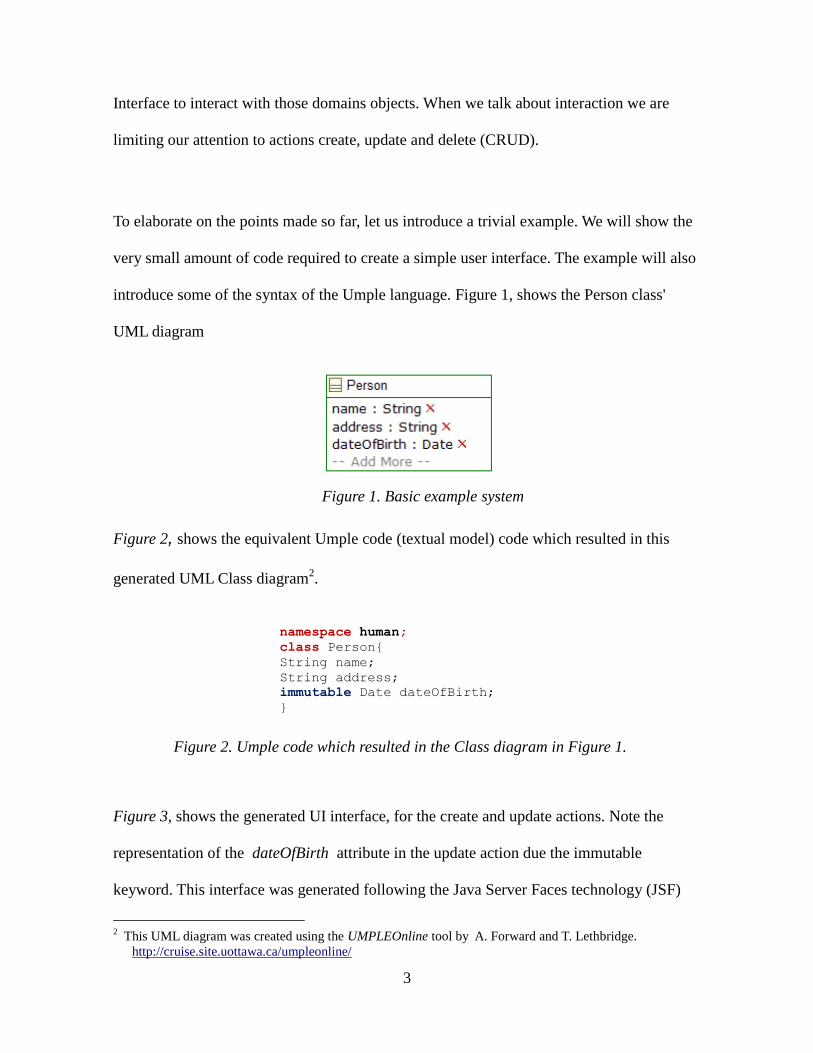
To elaborate on the points made so far, let us introduce a trivial example. We will show the
very small amount of code required to create a simple user interface. The example will also
introduce some of the syntax of the Umple language. Figure 1, shows the Person class'
UML diagram
Figure 2, shows the equivalent Umple code (textual model) code which resulted in this
generated UML Class diagram2.
Figure 3, shows the generated UI interface, for the create and update actions. Note the
representation of the dateOfBirth attribute in the update action due the immutable
keyword. This interface was generated following the Java Server Faces technology (JSF)
2 This UML diagram was created using the UMPLEOnline tool by A. Forward and T. Lethbridge.
http://cruise.site.uottawa.ca/umpleonline/
namespace human;
class Person{
String name;
String address;
immutable Date dateOfBirth;
}
Figure 1. Basic example system
Figure 2. Umple code which resulted in the Class diagram in Figure 1.

4
by Sun Microsystems
To give an idea of the effort required to build this simple CRUD, let us analyze the required
files and the number of lines of code. Since each UI technology requires different files and
programming structures, this analysis is not intended to be complete nor conclusive, but can
give us a preview of the usefulness of the UIGU.
Metric Value
Java Files 13
xhtml (view) files 5
Configuration Files 2
Total Files 20
Lines of Java code 394
Lines of xhtml code 174
Total lines of Code 568
Table 1. Person UI's Metrics
Figure 3. Person UI, generated from the Umple code, create (left) and update (right)
5
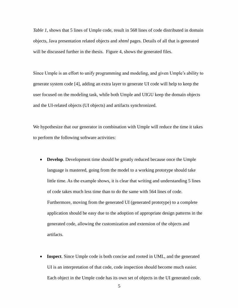
Table 1, shows that 5 lines of Umple code, result in 568 lines of code distributed in domain
objects, Java presentation related objects and xhtml pages. Details of all that is generated
will be discussed further in the thesis. Figure 4, shows the generated files.
Since Umple is an effort to unify programming and modeling, and given Umple‘s ability to
generate system code [4], adding an extra layer to generate UI code will help to keep the
user focused on the modeling task, while both Umple and UIGU keep the domain objects
and the UI-related objects (UI objects) and artifacts synchronized.
We hypothesize that our generator in combination with Umple will reduce the time it takes
to perform the following software activities:
Develop. Development time should be greatly reduced because once the Umple
language is mastered, going from the model to a working prototype should take
little time. As the example shows, it is clear that writing and understanding 5 lines
of code takes much less time than to do the same with 564 lines of code.
Furthermore, moving from the generated UI (generated prototype) to a complete
application should be easy due to the adoption of appropriate design patterns in the
generated code, allowing the customization and extension of the objects and
artifacts.
Inspect. Since Umple code is both concise and rooted in UML, and the generated
UI is an interpretation of that code, code inspection should become much easier.
Each object in the Umple code has its own set of objects in the UI generated code.

6
Maintain. Due to the model-code duality of Umple systems, maintenance also
should become much easier. Each change in the system will be reflected (by re-
generation) in the Umple-generated code and thereby in the UI generated code.
1.2 Audience
This thesis has been developed to expand the utility of the Umple language, so its audience
is similar to Umple‘s audience. Therefore, the target audience of this research is individuals
working in modeling, implementation, or maintenance of software systems, and also
Figure 4. Generated files for the Person class

7
students of software modeling courses who will find in UIGU a quick way to see how their
designs will look and behave in an implemented system.
Users are expected to have some experience with object oriented (OO) programming, and
UI technologies/frameworks in order to create or modify a specific UI provider (concrete
UI generator).
1.3 Organization
This thesis begins with a review of the background required to understand the main topics
of our research in Chapter 2. The background review includes Umple, code generation
models, UI Generation, UI Frameworks and certain design patterns.
The background discussion also includes a review of CRUD applications and the minimum
requirements that a CRUD application should fulfill. After reviewing these requirements,
we present the Umple subset supported by UIGU.
Chapter 3 will formally introduce the research questions explored within this thesis. The
answers to these questions are offered in Chapter 7.
We discuss the UIGU solution and provide a complete explanation of the different UIGU
components in Chapter 4. In this chapter, we present the concept of UIProvider, and the
JSFProvider is used to show a concrete implementation of that concept. Details about how

8
UIGU can be used are provided in Chapter 5. Chapter 6 describes another UIProvider (the
JFXProvider) to show how UIGU can be extended.
The last chapter, Chapter 7, provides answers to the research questions stated in Chapter 3,
and lists some valuable ideas to improve UIGU.

9
2 Background
In this chapter we present background research on four main topics: Umple, UI Generation,
UI Frameworks and certain design patterns. The first topic is the Umple language, its
features and the subset of Umple to be supported by the UI generator. The second deals
with the different generation approaches and which approach would work best with the
Umple language, keeping Umple‘s feature of generating system code for different
programming languages. The next section describes which UI frameworks can be used as a
generation target, that is, to which UI technologies the Umple-generated domain objects
would be linked. The final section discusses design patterns that are relevant to this work.
2.1 The Umple Language
The Umple language3 is both a text-based modeling language and a programming language
with modeling capabilities. It adds concepts from UML to object-oriented languages like
Java and PHP.
Umple takes care of generating essential target-language4 code needed to implement high-
level UML concepts such as attributes and associations, generating all the ―boilerplate‖
code (code which is necessary in a program to implement a concept and is repeated many
times) behind the modeling abstractions. This includes the methods needed to set and get
3 For a complete Umple reference see [4] 4 Examples in JAVA and PHP are available at http://cruise.site.uottawa.ca/umpleonline/

10
attributes as well as to add and delete links of associations; code is also created for some
design patterns like Singleton. The next few sections provide an overview of the central
aspects of the Umple language.
2.1.1 Namespaces and classes
The notion of namespace is equivalent to the concept of package in Java. That is, by using
the keyword namespace, the modeler can group related classes and provide access
protection to the group's classes (or types).
Umple classes are translated into classes in the OO target language (direct mapping). In
Umple, constructors are not explicitly declared, however Umple generates the target
language's constructor method based on the attribute modifiers, association multiplicities,
class hierarchy and other special keywords (singleton, key, etc.). Class hierarchies are
declared using the isA keyword in accordance with the is-A test [4]. Figure 5, shows a class
hierarchy declaration in Umple with two example attribute declarations.
Figure 5. Class and namespace declaration in a parent child hierarchy
2.1.2 Attributes
UMPLE translates an attribute declaration to a private instance variable and the standard
namespace human;
class Person {
name;
}
class Student {
isA Person;
Integer number;
}

11
get and set methods, where appropriate. Umple also generates code which checks certain
conditions based on attribute modifiers. Figure 6 shows an Umple model using some of
these modifiers.
Figure 6. Attribute modifiers.
By using attributes, the user can change the attribute implementation. For example, an
immutable attribute will allow setting the attribute value only at creation time but not
through a set method. In the simplest case each Umple attribute is mapped to a single
instance variable in the target language, but in more advanced cases (i.e. defaulted
attributes), Umple provides a set of methods that check that modification is done
appropriately.
2.1.3 Associations
Most of the power of Umple comes from the way it handles associations between classes
[4]. This is because classic OO languages do not offer a standard construct to support the
association concept. More recent languages like Ruby have started to recognize the
concept, but not to its full extent.
Umple maps all associations attributes like multiplicity (0, 0..1, n, *, etc), role names, and
namespace human;
class Person{
internal id;
String name;
String address;
defaulted Boolean
isMember=true;
settable Integer age;
immutable Date dateOfBirth;
}

12
navigability, into system code (e.g. Java) adding also methods to maintain the association
links, allowing deletion, addition, listing, and other utility methods. Figure 7, shows an
association example and the generated Java code (Appendix I shows Umple grammar).
namespace Airline;
class Airline{
String name;
1 -- * RegularFlight;
}
class RegularFlight{
Time time;
Integer flightNumber;
}
public class Airline {
private List<RegularFlight> regularFlights;
…
public List<RegularFlight> getRegularFlights() {
return Collections.unmodifiableList(regularFlights);
}
public int indexOfRegularFlight(RegularFlight aRegularFlight)
{
return regularFlights.indexOf(aRegularFlight);
}
public RegularFlight addRegularFlight(Time aTime, int
aFlightNumber)
{
return new RegularFlight(aTime, aFlightNumber, this);
}
...
public void delete()
{
for(RegularFlight aRegularFlight : regularFlights)
{
aRegularFlight.delete();
}
}
...
Figure 7. Association declaration in Umple (left), fragment of Java generated Code (right)
2.1.4 Other features
Umple contains other interesting features to provide ―out of the box‖ implementations of
common software constructions. The singleton keyword allows the declaration of singleton
types (only one object of the class is instantiated at runtime). Attributes can be declared to
maintain a state controlled by a state machine with transitions, guards, and actions. The key
declaration provides identifiers to determine if two instances are logically equivalent.
13
Ordinary methods are written in Umple in a form that is essentially identical to how they
would appear in Java (or PHP). However these methods contain certain restrictions; most
importantly they can access the instance variables representing associations and attributes
only through the generated methods, not directly.
2.2 Subset of Umple Supported by UIGU
This thesis focuses on how textual models can be extended to the UI level, that is using
both Umple models and the Umple metamodel, how a default user Interface and basic
actions can be generated. This work is primarily done as a proof of concept, and the
research is focused on the most common set of user related actions, which are the CRUD5
(create, read, update and delete) actions. In the conclusions, we talk about ways to extend
UIGU to support more advanced actions. Before talking about the selected subset we have
to determine what are the minimum features required to create CRUD applications.
2.2.1 Effective CRUD implementation
In its origin, CRUD was the most common acronym used to describe the basic set of
actions provided by a relational database system [6]. But today the term is extended to
many other persistent technologies, like xml databases, indexed files, object databases, etc.
Usually CRUD implies the capability to only store data in one table or entity, but in our
case the concept is extended to also allow the interaction with associations.
5 Others acronyms to denominate those actions are ABCD: add, browse, change, delete; ACID: add, change,
inquire, delete; etc.

14
Any effective CRUD implementation in an object-oriented system must allow:
Create: Create the required entity in the persistent layer (repository); all constraints
(null, max or min, uniqueness, etc.) must be respected, also links of the the 1--n
associations must be linked here, either for creation (create an instance of the the
associated class) or selection (choose an instance of the associated class).
Read: An effective CRUD should allow at least two selection methods: retrieve one
instance using a unique key or the entity itself, and retrieve all instances of the same
class.
Update: Associations and non-immutable attributes could be updated here; the
update technique (update only the modified fields or delete and create a new
instance) is an implementation decision. As in the create action, all constraints must
be respected.
Delete: This action takes care of the physical (destruction) or logical (deactivation)
elimination of an object or a group of objects. In an object-oriented system all
associations (and their multiplicities) must be respected either by allowing cascade
deletion or through the validation of the delete conditions.
2.2.2 The Subset of Umple Attribute Keywords to be Supported
As stated in Section 2.2.2, Umple translates each attribute into an instance variable. In any
strongly typed object-oriented language, instance variables must have a type [7] (the class
of objects that the variable can contain) and also they could have an access modifier, and an
initial value, in Umple the initialized value follows the semantics of the target language [8].

15
Since Umple has a similar syntax to Java, it is natural that the selected types are similar to
Java types. The initial set of types is:
Boolean: This type only supports two values: true or false, so as to allow for simple
flag checks and Boolean-related operations.
Integer: Implemented to allow the declaration of integer numbers.
Double: Added to support floating-point numbers, the decimal separator is the dot
(.)
String: Implemented to allow the declaration of chains of characters, when no type
is specified, this type is the default type used in the generated code.
Date: Added to allow the declaration of dates.
Time: Added to support time attributes in a 24h format.
Others types were omitted in this generator because they can be handled by the types
described above (i.e. char by String, Float by Double, etc.).
UIGU also supports Umple‘s initialized attributes; Table 2 shows the supported
initialization code when Java is the target language.
Umple provides ―out of the box‖ encapsulation [8] that is, all attributes are private and the
accessor (get) and mutator methods are public, implying that there are no access modifiers

16
in Umple strictly speaking. However Umple generates code to control the interaction
between the user (in our case the UIGU generated interface) and the attributes. To provide
such functionality, Umple uses a set of attribute modifiers. Basically those modifiers alter
the initialization logic, update behavior, and visibility.
Type Code Pattern
Boolean =new Boolean(true);
=true;
Integer =new Integer(5);
=5;
Double =new Double(5.2);
=5.2;
String = ―ABCDE‖
=new String(―ABCDE‖)
Date ="2001-08-11" yyyy-MM-dd
Time ="12:44:00" hh:mm:ss
Table 2. UIGU supported initialization for Java code generated by Umple
Types and initial values are central aspects of the Create and Update actions in a CRUD
application, since instance variables are not used in arbitrary ways, Umple introduced those
modifiers to abstract some recurrent patterns regarding instance variables‘ intentions [9].
The following list contains the initial set of modifiers supported by UIGU, each modifier
was chosen taking in account its importance in the related CRUD actions.
none: No modifier at all. If no initial value is specified, the attribute value is
assigned in the constructor; otherwise the attribute value is assigned to the specified
initial value. The attribute can be created as null. The attribute can be updated to any
value including null. Impact: Create and Update.

17
settable: Same as none. Impact: Create and Update.
immutable: if no initialization, the attribute value is assigned in the constructor, also
the attribute can be created as null; otherwise the attribute value is assigned to the
initial value. The attribute cannot be updated. Impact: Create and Update.
defaulted: The attribute must have an initial value; at creation time the attribute is
assigned to the specified initial value, The attribute can be updated or reset to the
initial (default value). Impact: Create and Update.
internal: If no initialization, the attribute value is assigned in the constructor;
otherwise, the attribute value is assigned to the initial value. The attribute can be
neither read nor updated after construction. Impact: Create.
key: This modifier indicates that the attribute is part of the unique key. Uniqueness
of keys is enforced, and an exception is thrown if the uniqueness is violated in an
attempt to instantiate an object. Key implies immutable, key attributes are necessary
to find and store entities in persistence layers. Impact: Read, Delete, Create.
2.2.3 Umple association subset
As commented in Section 2.2.3, Umple provides a way to declare associations as part of the
language. The declared associations can have role names, directionality and multiplicities.
UIGU generates UI code to allow the end user to interact with the declared associations.
Umple provides several styles to declare associations, all of them supported by UIGU;
these styles are:
Explicit: In this approach the classes are declared first, and then an association

18
structure is declared to indicate the link between them, along with their role names,
direction and multiplicities.
Implicit: The association and its roles are declared inside of one of the associated
classes, along with their role names, direction and multiplicities.
Figure 8 shows these two declaration styles. In this example the association states that a
school has at least one professor, and each of these professors only belongs to one school.
Figure 8. Styles to declare associations. Note the use of the arrow (->) to indicate direction,
the dots (..) to declare multiplicities and the role names (in this case professors).
The way we declare multiplicities in Umple is very similar to the way we declare them in
UML. UIGU generates validation methods to ensure that boundaries are respected. To
declare that an association is one way only, we simply use the ―->‖ construct instead of
―--―.
Currently, UIGU generates UI code for associations with all the multiplicity combinations,
with the exception of 1--1 associations. This is because the current version of Umple (1.6.3)
does not have a post-creation strategy6, and hence, the generated constructors have an
6 It is a two steps creation process. In the first step the object is created setting only its attribute, in the second
step (post-create), the associations are linked.
class School{}
class Person{}
association {
1 School --> 1..* Person
professors;
}
class School{
1 -> 1..* Person professors;
}
class Person{}

19
interdependency preventing the creation of the objects.
2.2.4 Design Patterns generated by Umple
Umple generates system code for classes marked as singleton; those classes are
implemented following the singleton pattern. This pattern ensures that there is only one
instance of a class at runtime. In Umple, this is declared using an optional expression
―singleton;‖ in the declaration of a class. UIGU generates the UI code to maintain
associations from and to singleton classes.
2.2.5 Class hierarchies
Class hierarchies are central to object oriented programs; to support those hierarchies,
Umple allows two styles to declare such hierarchical relationships. As with the association
declarations the two styles are:
Explicit: In this approach the child class uses the isA keyword followed by the name
of the parent class
Implicit: The child class is declared inside the parent class. This style of declarations
should not be confused with the notion of inner classes in OO programming.
Note that Umple supports only single inheritance, like Java and most other OO languages.
Figure 9 shows two equivalent class hierarchies with the different declaration styles.
Figure 9. Explicit (left) and Implicit (right) parent-child declaration
class Person{}
class Professor{
isA Person;
}
class Person{
class Professor{}
}

20
UIGU supports any number of levels of hierarchy and both types of declaration.
2.3 The Umple Metamodel
UIGU makes extensive use of the Umple metamodel to generate UI Objects (web pages,
Java Beans, etc), validation routines, persistence layer, and configuration files. Figure 10
shows the Umple core metamodel (version 1.6.3).
Figure 10. Umple core metamodel
21
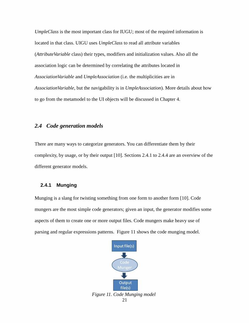
Figure 11. Code Munging model
UmpleClass is the most important class for IUGU; most of the required information is
located in that class. UIGU uses UmpleClass to read all attribute variables
(AttributeVariable class) their types, modifiers and initialization values. Also all the
association logic can be determined by correlating the attributes located in
AssociationVariable and UmpleAssociation (i.e. the multiplicities are in
AssociationVariable, but the navigability is in UmpleAssociation). More details about how
to go from the metamodel to the UI objects will be discussed in Chapter 4.
2.4 Code generation models
There are many ways to categorize generators. You can differentiate them by their
complexity, by usage, or by their output [10]. Sections 2.4.1 to 2.4.4 are an overview of the
different generator models.
2.4.1 Munging
Munging is a slang for twisting something from one form to another form [10]. Code
mungers are the most simple code generators; given an input, the generator modifies some
aspects of them to create one or more output files. Code mungers make heavy use of
parsing and regular expressions patterns. Figure 11 shows the code munging model.

22
Note that in this model there is no compilation step, special syntax or auxiliary files.
2.4.2 Inline code expanders
In this model the input files contain some special markup that is going to be replaced by the
generator, that is, the generator expands the original source. This implies that the output is
an expanded version of the input. An example of the implementation model is the Java
Server Pages -JSP- technology [11], where the input file is a jsp (or xml) page with special
tags, and the output is an html (or xhtml) page generated after the expansion
(replacement) of those tags. Code expanders are less extendible than code mungers, since
the mere choice of an expandable language reduces their possible uses [12].
2.4.3 Mixed code generation
A mixed code generator reads input file(s) and then modifies and replaces the file(s) in place.
Unlike inline-code expanders, mixed-code generators put the output of the generator back into the
input file(s). This type of generator looks for specially formatted comments, and when it finds them,
fills the comment area with some new source code required for production [10].
Figure 12. Inline code expander model

23
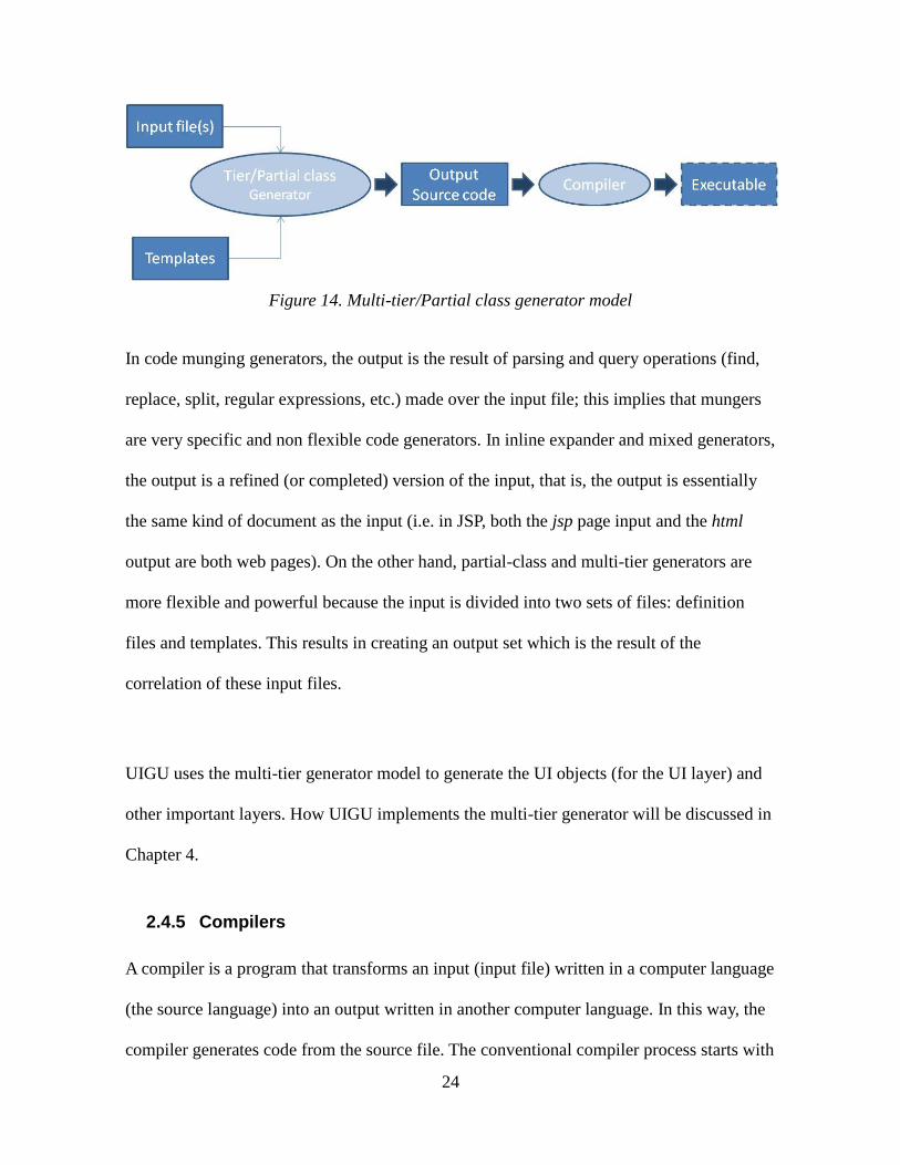
2.4.4 Partial-class generation and Multi-tier Generation
In these models, the input file(s) is (are) basically an abstract definition of the system. The
generator uses templates to create software artifacts (i.e. classes). These generators rarely
provide a graphical language for specification definition; therefore, they usually rely on
database metadata, tabular metadata inputs, properties files, etc., making them non-intuitive
and awkward [12].
The difference between a partial-class generator and a multi-tier generator is the scope.
Both of them apply templates based on the input definition files, but in the partial-class
approach the generator generates base classes to be extended (or derived) by the software
developer to create the production code. Multi-tier generators generate all the required
code for an entire layer or layers in an n-tier system. Partial-class generators can evolve into
multi-tier generators [10].
Figure 13. Mixed code generator model
24
Figure 14. Multi-tier/Partial class generator model
In code munging generators, the output is the result of parsing and query operations (find,
replace, split, regular expressions, etc.) made over the input file; this implies that mungers
are very specific and non flexible code generators. In inline expander and mixed generators,
the output is a refined (or completed) version of the input, that is, the output is essentially
the same kind of document as the input (i.e. in JSP, both the jsp page input and the html
output are both web pages). On the other hand, partial-class and multi-tier generators are
more flexible and powerful because the input is divided into two sets of files: definition
files and templates. This results in creating an output set which is the result of the
correlation of these input files.
UIGU uses the multi-tier generator model to generate the UI objects (for the UI layer) and
other important layers. How UIGU implements the multi-tier generator will be discussed in
Chapter 4.
2.4.5 Compilers
A compiler is a program that transforms an input (input file) written in a computer language
(the source language) into an output written in another computer language. In this way, the
compiler generates code from the source file. The conventional compiler process starts with
25
the parsing of the source file. It continues with the generation of an abstract syntax tree
(AST, a data structure that represents what has been parsed), the creation of an abstract
semantic graph (ASG) from the AST, and the translation of this graph into the target
language. 7
2.5 Code generators and input files
As shown in Section 2.4, all code generation models take input files (input definition files),
but the input does not have to be a file formally speaking. Indeed the input resources can
undergo a series of transformations before being consumed by the generator. Sections
2.5.1 to 2.5.4 discuss the characteristics of the UI code generators for a specific input set.
2.5.1 Database based UI code generators
Database tables along with database metadata contain enough information to generate entry
forms (UI forms) [13]. The metadata can come from the information schema or system
catalogs. In these catalogs, information about objects like tables, views, indexes, etc. is
stored; since the catalogs are normal database tables (but maintained by the DBMS engine),
they can be queried using regular SQL statements.
Obtaining information about database structure is crucial for the generation of UI artifacts
because the generator uses it to determine how to render the different UI components.
Column attributes like type, name, and length are used to translate and map each database
7 Compilers are a broad and extensive topic. In this research we are not going to delve into their details.

26
object to the generated objects in a specific programming language [14]. For instance, size
of the text field is determined based on the length of that column.
Following this approach, the generator is in charge of executing a set of SQL queries on the
catalog, iterating over the results and applying a decision structure to generate the required
UI artifacts.
One of the advantages of this approach is that database engines have a very rich set of
attributes and constraints (null, unique, foreign keys, checking constraints, etc.) that helps in
the creation of elaborate UI objects and the relationships between them, also entity-
relationship diagrams (ERD) share many concepts with class diagrams, allowing mapping
between them [15].
The main disadvantage of this approach is that each database creates and maintains its
catalog of tables in a proprietary way; this means that a generator created for a specific
DBMS (i.e. PostgreSQL) should be rewritten if the DBMS (not the database structure) is
changed. To reduce the impact of this problem Mgheder and Ridley in [16] propose the
conversion of the fetched metadata into XML files and the use of them as the UI generator's
input (definition) files. XML based code generators will be discussed in 2.5.3.
2.5.2 Reflection-based UI code generators
Use of reflection is more often seen as an alternative to code generation than as an effective
code generation approach itself. Using super classes to put methods with features made by
the use of reflection is an approach to implement common behavior in a set of more simple
27
classes [17]. Since reflection calls are made at runtime the reflection approaches have
some key disadvantages:
Reflection code is complex and hard to test and debug.
Discovering and manipulating classes in runtime can create memory and
performance issues.
Reflection challenges the principle of information hiding and the access controls
developers have specified, so its use should be minimized.
To overcome these issues, Rettig and Fowler suggest [18] the use of reflection to generate
those super classes in a preliminary code generation phase.
In a reflection-based code generator, the input file is a compiled class or set of classes. The
amount of information that can be obtained using reflection depends on the reflection API
of the target language. As can be seen in [17] and [18], reflection techniques are useful to
generate some specific functionality (i.e. persistence responsibilities, marshalling data,
etc.).
2.5.3 XML/XSL based UI generators
XML generators make heavy use of xml related technologies like XPATH and XSLT.
XPATH is a query language designed to select nodes in a XML document [19]. XSLT
(Extensible Style sheet Language: Transformations) is a language defined to transform an
XML document into another XML document; however, XSLT can also generate different
types of documents (structured or not). XSL documents contain a set of templates (rules) to

28
be executed when the walking logic matches (using XPATH) the fragments declared in the
templates.
In the XML approach, the input language is an XML file set. However, there is no
restriction on what the output can be [20]. XSLT scripts can be written to process the XML
documents conforming to the input language and generate output documents in various
required forms.
XML based code generators have at least the following phases [21]:
Parsing: The XSLT processor parses the input XML files.
Tree Building: The XSLT processor constructs a node/branch tree and provides
access to the tree using XPATH. The processor should populate the tree.
Tree walking: This is done using XSLT‘s programmatic constructs and functions in
combination with XPATH to apply and match the defined templates for the defined
XML fragments.
Writing: XSLT text-related functions write the result to an output stream.
Another technique is to use a XML schema (xsd) as an input instead of an XML instance.
XML schemas have a complete (“out of the box”) defined set of attributes and properties
that can be transformed (using XSLT) into common software definitions like: types, default
values, boundaries, inheritance, etc. However an xsd file is also an XML file, so, these code
generators are also XML-based code generators.

29
One of the most important advantages of XML GUI based generators is that many GUI
technologies use XML-like documents (i.e. html, xhtml, wml, mxml, etc.), making the
generation process a transforming process between documents of the same kind [22]. In
addition, XML is a fully standardized language with many supporting libraries and tools.
In the other hand, among the disadvantages of XML-based generators are
XSLT is not a complete programming language; there are transformations that
cannot be done using only XSLT.
XSLT is a functional language with no side-effects. There are many ‗habit
adjustments that application programmers need to make before becoming
comfortable with XSLT programming [20].
The XSL documents created to generate non-XML documents can be difficult to
read and understand, and hence to maintain.
When the source of the input definition file is not XML, an additional step is required. That
is, to create an XML file based on the definition file. This XML file is an intermediate
representation of the input.
2.5.4 Templates
Template files are also input files for multi-tier/partial class code generators. When the
output files are both complex and structured, template technologies become handy to
separate the code definition logic (basically the information in the input definition file set)

30
and the code formatting structure. This means that the format of the output files is explicitly
declared in the template. Templates are also an effective way to modularize and reuse
common structures.
In this research we selected the Java Emitter Template (JET) technology to generate both
source and the UI code. We use template technology not only because Umple uses JET
extensively in the generation process, but also, because JET is simple and easy to
understand.
JET is a component of the Eclipse Modeling Framework (EMF) project. The templates
work using a subset of the Java Server Pages (JSP) syntax [23], where the code within
―<%‖, ―%>‖ tags is directly copied over to the resulting file, and code outside of these is
passed as parameters to StringBuffer.append(…) operations. The templates files are
compiled, resulting in an intermediate component, which is a Java class with a generate
method. The generate method takes a parameter of type Object, to customize the generated
files (or fragments).
Other template technologies are ERb[24] and MASON[25].
2.6 Design Patterns
Umple generates the domain objects, but our target is to generate a fully operative default
user interface. To achieve this we have to fill some gaps to link the UI with the domain
objects. In the following sections we are going to present an overview of three design

31
patterns used in UIGU to fill these gaps.
2.6.1 Model View Controller
MVC is a design concept that attempts to separate an application into three distinct parts:
Model, View and Controller. The model is made up of application data and business rules,
it is the core of application and controls data access and data update; the View is in charge
of the expression of model content and it receives data from model (through the controller)
and decides the data show form [26].
The logical separation of the application into these parts ensures that the Model layer is
completely independent of how it is rendered. It is restricted to just represent the domain
objects of the application and to implement the business logic. Likewise, the View layer is
responsible to render (display) the data, and the implementation of the validation logic to
ensure the coherence and integrity of the user input. The Controller directs the user to the
views to be displayed and notifies the model layer of data changes and requests for
retrieval.
The MVC approach is largely based on an event-driven environment in which the user
drives the flow of the application by using the interface [27].
In UIGU, the Model is represented by the domain objects and a persistence layer; the View
and the Controller are responsibilities of each UI provider. The next section will discuss
the pattern used in that persistence layer. Chapter 4 will talk about what UI providers are.

32
2.6.2 Data Access Object (DAO)
In many software applications, domain objects have to persist (i.e. store) their data.
However there are many different storage mechanisms like mainframe systems,
Lightweight Directory Access Protocol (LDAP) repositories, relational databases, etc. Such
disparate data sources offer challenges to the application and can potentially create a direct
dependency between application code and data access code [28].
The DAO pattern provides a solution to avoid this dependency by the creation of a new
layer (the DAO layer) to encapsulate all data access code. The DAO completely hides the
data source implementation details from its clients. As a requirement, the DAO‘s public
interface should not change when the underlying data source changes, in this way the DAO
helps to adapt the application to different storage schemes without affecting upper layers
and/or components. Essentially, the DAO acts as an adapter between the components and
the data source.
Another advantage of this approach is that the development of the application can be
divided into more teams, which will, according to their expert knowledge, work on the data
access objects or on the implementation of business processes in the business logic tier
[29].
Figure 15 shows a common DAO design.

33
Figure 15. DAO pattern, class diagram
The DAO pattern defines the following classes [29]:
Client: represents the component or layer, which requires access to the data source
to select, update, delete and insert data
AbstractDAO : Interface to be implemented by the ConcreteDAO, this approach
assures that the Client logic, referencing this interface type, will remain intact if the
ConcreteDAO is replaced or modified.
ConcreteDAO – This class abstracts the underlying data access implementation for
the Client.
DataSource - Represents a data source implementation (i.e. RDBMS, XML
repository, CSV files, etc.)
ValueObject - Represents a transfer object used to decouple the Client from
ConcreteDAO.

34
UIGU uses the DAO pattern to register the instances created by the user. The Concrete
DAO implementations (FakeDAO) use a HashMap to keep the instances alive during a user
session. Chapter 4 will talk about the DAO object generated by UIGU.
The following section discusses how the flexibility of the DAO pattern can be increased by
the adoption of the Abstract Factory pattern.
2.6.3 Abstract Factory
The access to one particular data source will generate a certain number of data access
objects (DAOs); this group of objects can be considered as a ―family‖ of objects. The
abstract factory pattern allows the creation of each specific ―family‖ of DAO objects by the
implementation of a factory object. From the implementation point of view, the application
should provide a different factory for each data source (i.e. OracleDAOFactory,
XMLDAOFactory, etc.). This strategy defines the creation of an AbstractDAOFactory that
can construct various types of concrete DAO factories, once the client instantiates the
required DAOFactory, the client uses it to get the implemented DAOs for the defined data
source. Figure 16 shows the DAO pattern using the AbstractFactory pattern.
To allow the customization and extension of the generated prototype, UIGU generates a
DAO+AbstractFactory layer, to allow the switch from the generated FakeDAO to a real
persistent mechanism in a clear and simple way.

35
Figure 16. DAO + AbstractFactory, class diagram
2.7 UI Frameworks
One UIGU feature is the possibility to generate UI code for different UI technologies. For
this purpose, UIGU introduces the concept of render providers. A render provider (UI
provider) is a concrete UI generator for a target technology. As a proof of concept in this
research we developed two render providers: a Java Server Faces provider and a JavaFX
provider. Sections 2.7.1 and 2.7.2 are an overview of those technologies. Render providers
are defined in detail in chapter 4.

36
2.7.1 Java Server Faces (JSF)
Java Server Faces is a standard Java framework for building user interfaces for Web
applications. Its key advantage is that it simplifies the development of the user interface,
which is often one of the more difficult and tedious parts of Web application development
[30].
Java Server Faces was designed to simplify the development of user interfaces for Java
Web applications in the following ways:
It provides a component-centric and client-independent development approach to
building Web user interfaces.
It simplifies the access and management of application data from the Web user
interface.
It automatically manages the user interface state between multiple requests and
multiple clients.
To provide flexibility, JSF technology introduced the notion of render kits. A render kit
defines how component (graphical control) classes map to component tags that are
appropriate for a specific client [31]. The Java Server Faces implementation includes a
standard HTML render kit for rendering to an html client. There are render kits for other
technologies like xhtml, wml, svg, etc.
Like any other web application, a JSF application is made by different pieces (or
components), a JSF application should include:

37
A set of web pages (jsp, html, wml, etc.).
A set of backing beans (or managed beans), components that define properties and
functions for UI components on a web page.
A set of faces-config.xml files to define page navigation rules, configure the backing
beans and configure other custom objects.
A web.xml (deployment descriptor).
Custom objects and custom tags.
The backing beans life cycle is controlled by the JSF framework using the scope element in
the respective Managed-Bean declaration. Table 3 shows the different scopes available
[31].
Scope Description
None These beans are not instantiated nor stored in the request, session, or
application objects. Instead, they are instantiated on demand by another
managed bean. Once created, they will persist as long as the calling bean
stays alive because their scope will match the calling bean's scope.
Request These beans are instantiated and stay available throughout a single HTTP
request. This means that the bean can survive navigation to another page
providing it was during the same HTTP request.
Session These beans will be stored for the HTTP session. This means that the values
in the managed bean will persist beyond a single HTTP request for a single
user. This means that the beans are going to be available during multiple
requests.
Application These beans retain their values throughout the lifetime of the application and
are available to all users.
Table 3.Backing Beans scope
In order to handle the different tasks required to build and interact with a web application,
the JSF architecture provides a rich set of UI components and a complete group of models
to support those components. Table 4 shows the available JSF models.

38
Model Description
Rendering model Defines how to render the components.
Event and listener model Defines how to handle component events.
Conversion model Defines how to register data converters onto a component.
Validation model Defines how to register validators onto a component.
Table 4. JSF Models
In UIGU, the JSF render provider is responsible for the generation of the xhtml pages,
configuration files (web.xml and faces-config.xml), backing beans and other utility classes.
Chapter 4 will discuss in depth UIGU's JSF render provider.
2.7.2 Java FX
JavaFX is a rich client platform for building cross-device applications and content.
Designed to enable easy creation and deployment of rich Internet applications (RIAs) with
immersive media and content, the JavaFX platform ensures that RIAs look and behave
consistently across diverse form factors and devices. JavaFX applications are not restricted
to web browsers; in fact JavaFX also allows the creation of desktop applications.
Java FX provides a complete set of UI components (called controls) to build GUI
applications along with an event model and a data binding model. JavaFX applications are
written in a Java-like language called JavaFX scripting language. the JavaFX API provides
methods to interact with Java objects and Java also has APIs to interact with JavaFX
components.
We chose JavaFX to show how UIGU can generate a default UI for different UI

39
technologies, even though those UIs have to be generated in a different programming
language. In Chapter 6 "Extending UIGU", we use the JavaFX render provider to discuss
how to create new providers and how to extend them.

40
3 Research Questions
This chapter is a formal statement of the research questions this thesis explores.
3.1 From the model to the UI
As mentioned in Chapter 1, if modelers can go from the model to a working prototype (or
default UI), we believe they would be better able to understand the implications of their
design decisions, to evaluate alternatives and to validate their designs. Prior to the
development of Umple, changes in the model could not be instantly reflected in
implemented code for the system. Umple filled that gap [4], however there was still another
gap to fill: changes in the model were still not immediately visible in the UI, so modelers
could not get instant feedback about the implications of modeling changes. The first
research question we will therefore investigate is:
RQ1: How can we bridge the gap between models and the UI?
The criterion of success in answering this question would be that the generated UI follows
the model definition correctly in terms of attributes, associations, multiplicity and
modifiers.

41
3.2 The Umple abstract semantic graph as an input
In this research, we are proposing the use of the Umple abstract semantic graph (where
each node is an instance of the Umple metamodel) as an input to the code generator.
Therefore, the second research question we will investigate is:
RQ2: What are the advantages and disadvantages of generating UI code starting with the
abstract semantic graph generated by the Umple compiler?
3.3 Generation scope
Like any other modeling tool, the information contained in an Umple system is limited.
In order to create a meaningful user interface, generating a UI using only the model (and its
metamodel), will create a boundary around what information can be determined, what can
be assumed, and what information is missing. The third research question we will therefore
investigate is:
RQ3: What are the limits of automatic UI generation from models?
3.4 Usefulness
The generated code should be clean and adaptable to a real world application. We intend to
improve the usefulness of the default UI by the integration of well-known design patterns
and programming language practices with our generated artifacts.

42
RQ4: To what extent can generated default UI code be customized and extended?
3.5 Multi-UI generation
Since Umple is a family of languages [4] rather than a single language, creating a UI
generator for Umple should involve the development of different UI generators for each
technology, however, instead of programming multiple generators, we are going to explore:
RQ5: How can a GUI generator generate UI code for different UI technologies?

43
4 The UIGU Generator
UIGU is a template based multi-tier code generation software system referred to throughout
this thesis. This software is an effort to provide a default user interface for a defined Umple
model and therefore to fill the gap between the domain objects and the UI layer.
After defining which were the operations that the generated UI should provide and the
Umple subset that it should support; our next question to address was: What is the most
suitable kind of generator to implement? The first version of UIGU was intended to be
independent of the Umple language, and this early version made extensive use of reflection
techniques over the Umple-generated Java classes. By the use of reflection, it was possible
to discover some characteristics of the attributes and the associations, but many
disadvantages were found:
The immutable property of attributes cannot be determined because Umple creates
set methods for these attributes that simply return an error indicator.
Association multiplicities cannot be determined. Umple generate if conditions in the
body of the add and remove methods, and these checks cannot be obtained by
reflective calls.
There is no link between association roles. If two classes have two (or more)
different associations between each other, it was not possible to determine which
pair of variables represents each association. Figure 17 shows an example to
illustrate this problem. Using only reflection, it is not possible to determine the ends

44
of each association.
The Java compiler (v. 1.6) drops the parameter names. If a constructor takes two or
more attributes as parameters and these attributes have the same type, is not possible
to determine which parameter represents each attribute.
Some of the problems listed above can be overcome if the designer employs better design
approaches, but our UI generator should be capable of generating more than just well-made
designs. Adding additional information in the form of Java annotations could help the
reflective generator to create the UI, but this involves the modification of the Umple
language. However, our target is to create a generator that fits Umple and not to fit Umple
into a generation approach.
Since Umple does all the compilation steps (parsing, building the abstract syntax tree,
populating the abstract semantic graph, etc.), the implementation of a compiler was
redundant. Figure 18 shows the points in which the generation process takes place. Having
the Umple model and its abstract semantic graph (Umple metamodel class instances) as
class School{
* job -- * Person professors;
* school -- * Person students;
}
class Person{}
public class School{ private List<Person> professorss; private List<Person> studentss;
…
}
…
public class Person {
private School job; private School school;
…
}
Figure 17. The Association problem. Umple code (left), Java generated code (right)

45
inputs, the adoption of the multi-tier generation model to develop a more complete
generator was found to be appropriate for the following reasons:
Regarding the input:
o The ASG can only be inspected when the Umple compiler is running. When
the Umple compilation process is completed, the ASG of a specific model
does not exist anymore. The use of XML/XSL approaches implied the
creation of an intermediate representation of the metamodel to apply the
transformations.
o The Umple code generator is a template-based generator. UIGU, as an
Umple tool, had to follow the Umple generation approach.
Regarding the requirements:
o The UI layer is a complete tier. Hence, partial class generators are not
suitable.
o The outputs (GUI and other support objects) are based on the inputs, but
they are not an expanded version of them, so inline and mixed code
generators cannot be used.
o The generator had to be flexible enough to generate UI code for different UI
frameworks. Since code mungers are tied with the desired output, to create a
different output is necessary to develop a different munger.
To keep the separation between the domain objects and UIGU's generated objects, the
result of the generation process is a complete MVC application with Umple domain objects
and a generated Data Access Object (DAO) set as model. This generated application

46
provides a set of CRUD operations for each class defined in the model. In Section 4.3.5 we
will discuss the architecture of the generated application.
Figure 18. UIGU inputs. Try 1: Umple generated java classes. Try 2: Instances of the
Umple metamodel (Abstract semantic graph)
A key concept introduced by UIGU is a fragment. A fragment is a portion of specific UI
code that can render a UI component or set of components that represent either an attribute
or an association for a defined CRUD operation or step, e.g. for one String immutable
attribute. The create fragment can be a label with the attribute name and a textbox to
receive the value from the user input, and the edit (update) fragment can be just two labels,
(because of the immutable modifier) one with the attribute name and the other with its
value. Section 4.1.2 explains the defined fragments and their applicability.
4.1 UIGU key concepts
This section describes the concepts required to understand the UIGU solution. In Section
2.2.1 we discussed each CRUD operation. From an implementation point of view some of

47
these operations can be divided into several intermediate steps.
4.1.1 CRUD intermediate steps
In a GUI application, each crud operation can be divided into several steps as follows:
Create:
o Pre-construction: Some of the values gathered from the user input have to
be processed/transformed into the types and formats expected by the
constructor of the class to be instantiated. For instance, a String variable
used to represent a date has to be converted into either a Date object or
Timestamp object.
o Key construction: The key declared fields in the models have to be used to
check the uniqueness of the new object.
o Construction: Both the formatted values and the keys are passed as
parameters to the construction mechanism (i.e. a constructor, an SQL insert
statement, a DAO create method, etc).
Read:
o Key construction: key fields are used to create the required Key to retrieve
the data.
o Prepare for edit or view: The data retrieved from the model have to be
formatted and converted into a user understandable format. (e.g.. a
timestamp into a date)
Update:
o Copy: The modified values gathered from the user input have to be assigned
to the fields of the instance under modification. This copy also implies data
transformation.
o Save: The instance with the new values is saved.
Delete:
o Key construction: key fields are used to create the required key to invoke

48
the delete operation (i.e. a SQL delete statement, an ejbRemove, etc.)
o Delete: The actual deletion (logical or physical) of the instance.
4.1.2 Fragments
As we introduced before, a fragment is a portion of UI code. Since the generated
application follows the MVC pattern, the fragments can be classified in two categories:
View fragments
Controller fragments
A view fragment represents the code that renders a graphical component (i.e. checkboxes,
calendars, textboxes, etc.) to the final user and its link (binding) with the related attribute or
association in the model. The generated graphical UI components have to follow either the
declared modifiers of the related attribute, or the navigability and multiplicity in the case of
an association.
A controller fragment represents the code necessary to communicate the graphical
components with the model layer in both ways: from the GUI to the model and from the
model to the GUI.
4.1.3 Generation Unit
A generation unit is the definition of an artifact to be generated as the result of the
integration of different fragments and templates into a single file. Each artifact (html page,
xml descriptor, css style sheet, java class, etc.) is defined in a generation unit. Different
generation units can share common fragments.

49
4.1.4 GUI properties
These properties are a set of constants defined to be used in the generation process. Some
of them are used for the generator itself (i.e. the output folder) and others are used by the
generation units (i.e. name suffixes, package prefixes, etc.).
4.1.5 Support files
Support files are the files required for the generated application to run properly, but are not
generated by Umple or UIGU. These include images, libraries, etc.
4.1.6 Umple Project
The ensemble of the Umple model, the GUI properties, the generation units and support
files conforms to an Umple model. This means that the objective of the UIGU generator is
the creation of the artifacts defined by an Umple model.
4.2 UIGU design aspects
In Chapter 3 we formulated the research question: How can a GUI generator generate UI
code for different UI technologies? Most of the design decisions made in UIGU‘s
implementation were adopted to provide such flexibility. To understand UIGU‘s
architecture, it is crucial to mention that a programming language usually has more than
one UI framework, even for the same GUI technology. For instance, Java Enterprise
Edition (JEE) provides UI technologies like the Servlet/JSP technology, but for this single
technology there are many UI frameworks, i.e. Struts, Tapestry and Expresso; all of them
are Java web frameworks and moreover, they are an implementation of the MVC pattern.

50
Each framework has its own libraries, configuration files, controller objects and even its
own html (or xml) tags. This makes most of its source files completely different and not
interchangeable. For PHP, many UI frameworks are also available, i.e. CakePHP,
CodeIgniter and Zend; like in Java's case, they are MVC frameworks, and each one has its
own set of objects, configuration files, tags, etc.
Since each programming language has more than one UI technology and each UI
technology has many UI frameworks, it was decided that the UI Generator had to split the
generation responsibilities into three different levels.
The upper level should take care of all common tasks between different programming
languages:
Read both the Umple model and its metamodel.
Provide a mechanism to locate and instantiate the code fragments (but not the
fragments themselves).
Create and initialize the backing objects that are going to be used by the Generation
Units to generate the required files.
Take care of all file system related activities (read files, write files, create folders,
etc).
Provide all the functionality required to configure and use the generator.
Provide a set of interfaces to be implemented by the lower levels.
The middle level is in charge of the common tasks between different UI technologies for a

51
given programming language:
Provide a mechanism for registering and tracking (persistence) the objects created
by the user.
Provide default implementation classes for the interfaces declared in the upper level.
Each class has to contain common code and routines in order to be extended by
classes in the lower level.
The lower level has to provide the UI fragments for a specific UI framework and a specific
programming language:
Provide all the fragments required by the generation units.
Provide the configuration files required by the target framework.
Extend the default implementation provided by the middle level to add specific
methods and utilities.
UIGU, like Umple, uses JET technology to create the required templates for both the
generation units (which are templates that consume other templates) and the fragments.
The following section will provide an example to show how UIGU implements these three
levels. This example uses a concrete UIGU implementation of a Java Server Faces UI
generator for the Java programming language.

52
4.3 UIGU Architecture
In UIGU the levels described in the previous section are named (from top to bottom):
Model, Generator and Provider. Figure 19 shows UIGU‘s high-level architecture.
4.3.1 GUIModel
This component is responsible for the creation of the Umple Project, which is the final
result of the generation process. Figure 20 shows the GUIModel’s class diagram.
GUIModel’s classes and interfaces were designed to perform all upper layer tasks defined
in Section 4.2. This component encloses the common functionality and services required to
generate GUIs regardless of both the target programming language and the target UI
framework. Also the GUIModel declares the interfaces to be implemented by the Generator
and the Providers to integrate both specific language and specific UI framework artifacts.
In the following subsections we are going to present the key classes and interfaces of the
GUIModel component.
Figure 19. UIGU high level architecture

53
4.3.1.1 IGenerator
The IGenerator interface only declares the generate(…) method. This method takes an
Object as argument and returns a String object with the generated code. All fragment
classes have to implement this interface. Details about how JET-generated classes can
implement an interface will be discussed in Section 4.3.3.1.
4.3.1.2 UIProvider
In Section 4.1.2 we classified the fragments into two main categories: view and controller.
The cruise.ui.interfaces.UIProvider interface declares the required methods to be
implemented by a concrete UIProvider in order to return the appropriate fragments. Tables
Table 5 and Table 6 show the different declared methods and their purposes, for the
controller and view fragments respectively.
Method Purpose
getSetFragment Returns the attribute set method.
getGetFragment Returns the attribute get method.
getDeclarationFragment Returns the code required to declare the attribute as
an instance variable.
getAsignationFragment Returns the code required to assign a variable‘s value
to the attribute.
getCopyFragment Returns the code required to copy the value from an
attribute to the current attribute.
getPreConstructorFragment Any code (usually transformations) required before
the creation of the instance that owns the attribute.
getReverseCopyFragment Returns the code required to assign the attribute value
to a variable.
Table 5. UIProvider's methods for controller fragments

54
Figure 20. GUIModel class diagram

55
Method Purpose
getGUICreateFragment Returns the UI code required to draw the attribute‘s
linked UI component for the create operation.
getGUIEditFragment Returns the UI code required to draw the attribute‘s
linked UI component for the edit operation.
getGUIGridFragment Returns the UI code required to present the
attribute‘s value as a column in a grid.
getGUIGridHeaderFragment Returns the UI code required to configure the
header of the attribute‘s column in a grid.
Table 6. UIProvider's methods for view fragments
All methods described above return an IGenerator object and take two arguments: an
AttributeVariable, and a String varargs. The AttributeVariable object was briefly introduced
in Section 2.3. The varargs argument is used to pass parameters to the declared fragment.
The parameter replacement is done by the cruise.model.ParamaterManager utility class. To
do so each parameter in the template has to follow the signature #n# where n is the number
of the parameter to be replaced by the nth
value in the varargs.
The getClassMap() method is provided to return a HashMap with all declared classes in
the Umple model. Using this method, it is possible to obtain all associations and attributes
declared in an Umple class having its name (type).
4.3.1.3 UmpleProjectWriter
The cruise.writer.UmpleProjectWriter class provides the functionality to read the Umple
model and to write the generated Umple Project. UIGU has to be configured with an xml
file created following the xml schema (xsd) declared by the file UmpleProject.xsd (Please

56
refer to Appendix II ).
The configuration file (referred in this section as UmpleProject.xml) contains sections
(tags) to configure the three components required to generate the UI application for a
specific framework. This implies that UIGU generators for either different languages or
different UI frameworks should have their own configuration files.
The following is an explanation of the structure of the UmpleProject.xml file:
UmpleProject tag: This is the UmpleProject.xml’s root tag, and it is the parent of the
Properties, GenerationUnits and Files sections. Table 7 describes UmpleProject
tag's attributes.
Attribute Purpose
Name The name of the generated application.
UIFactory The provider to be used to render the GUI. i.e. the value
cruise.jsf.factory.JSFFactory, indicates that the Model will use the
JSFProvider.
OutputFolder The absolute path of the folder where all generated files have to be
created and all declared files have to be copied.
UmpleFile The absolute path of the Umple model file.
Table 7. UmpleProject tag
Properties: In this section, all configurable options have to be declared in a Property
tag. Some of these options are exclusively for the Model, Generator or Provider
components, while others can be shared across all of them. For instance, if the
UmpleFolder property is declared , the GUIModel will copy the generated Umple
classes to the declared folder relative to OutputFolder. Table 8 shows the Property

57
tag's attributes. The properties are accessible from all components.
Attribute Purpose
Name Property name
Value Property value
Table 8. Property tag
GenerationUnits: In this section, all generation units have to be specified. Note that
both the Generator and the Provider can create GenerationUnits, but from the
Model point of view there is no difference in the generation process (for more
details about the generation process, see Section 4.3.4). Table 9 shows the attributes
of the GenerationUnit tag. It is important to highlight the ParameterType attribute.
This attribute indicates what kind of argument is expected by the declared template
to generate the output. Table 10 describes the values accepted by this attribute.

58
Attribute Purpose Accepted values
TemplateClass The class name of the template to be
instantiated to generate the output.
Any IGenerator concrete
class
TemplatePackage Template Package of the declared
template class
It must use the dot (.) notation
(i.e. cuise.template.jsf)
ParameterType The kind of argument required by
the declared TemplateClass
NORMAL_CLASS_BY_CLASS
SINGLETON_CLASS_BY_CLASS
ALL_CLASSES
NORMAL_CLASSES
SINGLETON_CLASSES
NONE
PackagePreffix The package definition of the
generated file(s). This package is
translated to a folder hierarchy.
It must use the dot (.) notation
(i.e. web.pages.Airline)
ClassSuffix A suffix to be concatenate to the
generated file(s)
Any valid class and file name
(spaces, special characters,
slashes, etc. are not allowed)
OutputName Name of the generated file. This
attribute is ignored if the
ParameterType is set to
NORMAL_CLASS_BY_CLASS
or
SINGLETON_CLASS_BY_CLASS
Any valid class and file name
OutputExtension The extension of the generated
file(s)
Any valid extension
OutputSubFolder Indicates a subfolder relative to the
output folder to place the generated
files. If PackagePreffix is declared,
the folder hierarchy is created inside
the indicated subfolder
Any valid folder name
AddClassNameToRoute Indicates if a folder with the class
name has to be added at the end of
the folder hierarchy declared in
PackagePreffix
YES/NO
Table 9. GenerationUnit xml tag

59
ParameterType Purpose
NONE It passes a null value to the declared
TemplateClass. The output is just one file
with the package, name and extension
declared in the related attributes.
NORMAL_CLASS_BY_CLASS It passes all non singleton Umple classes to
the declared TemplateClass in a one-by-one
fashion. The output is as many files as non-
singleton classes are declared in the Umple
model. Each file has the package and
extension declared in the related attributes,
and its name is the class name concatenated
with the declared ClassSuffix.
SINGLETON_CLASS_BY_CLASS It passes all singleton Umple classes to the
declared TemplateClass in a one-by-one
fashion. The output is as many files as
singleton classes are declared in the Umple
model. Each file has the package and
extension declared in the related attributes,
and its name is the class name concatenated
with the declared ClassSuffix.
ALL_CLASSES It passes a List with all classes declared in
the Umple model to the declared
TemplateClass, the output is just one file
with the package, name and extension
declared in the related attributes.
NORMAL_CLASSES It passes a List with all non singleton classes
declared in the Umple model to the declared
TemplateClass, the output is just one file
with the package, name and extension
declared in the related attributes.
SINGLETON_CLASSES It passes a List with all non-singleton
classes declared in the Umple model to the
declared TemplateClass. The output is just
one file with the package, name and
extension declared in the related attributes.
Table 10. ParameterType's accepted values
Files: All files and directories to be copied inside the output folder must be declared
in this section; files are copied with no transformations. This section supports the

60
use of two different child tags: Directory and File. Directory copies the contents of
the specified directory, and File copies only the declared file. Tables Table 11 and
Table 12 show their respective attributes.
Attribute Purpose
InputFolder The absolute path of the folder to be copied-
OutputFolder The destination folder, relative to the UmpleProject‘s OutputFolder
attribute.
Table 11. Directory tag
Attribute Purpose
InputFolder The absolute path of the folder containing the file to be copied
OutputFolder The destination folder, relative to the UmpleProject's OutputFolder
attribute.
Name Name of the file to be copied.
Table 12. File tag
UmpleProjetWriter uses JAXB [33] (Java Architecture for XML binding) classes to read
the UmpleProject.xml file. Those classes are: ObjectFactory, UmpleProject,
GenerationUnits, GenerationUnit Properties, Property, Files, File and Directory. These
classes are declared in the cruise.jaxb package.
The method generateUmpleProject(…) takes an UIGenerator as parameter to generate all
output files following the configuration and properties specified in the UmpleProject.xml
4.3.1.4 UIGenerator
The main purpose of this interface is to provide methods to access the declared classes in
the Umple model. These classes are divided into two categories: normal and singleton. The

61
concrete UIGenerator should implement this interface and declare the methods to obtain all
classes, all singleton classes and all normal classes (getAllClasses(), getSingletons() and
getClasses() , respectively).
This interface also declares methods to get the Properties defined in the UmpleProject.xml
(getProperties()), and a reference to the UIProvider.
4.3.1.5 FragmentResolver and GUIFragmentResolver
These (Resolver) classes were implemented to resolve the fragments required by an
attribute for the complete set of CRUD steps given the attribute‘s type and modifier. To do
so, they require a Map parameter in their respective constructors. The Map parameter
contains AttributeFragmentProvider objects for FragmentResolver and
GUIFragmentProvider objects for GUIFragmentResolver. AttributeFragmentProvider and
GUIFragmentProvider are wrapper classes with the appropriate get methods to retrieve the
fragments (i.e. getCopyFragment(…), getCreateFragment(…)). In order to generate the
code fragment, these get methods take an AttributeVariable as a parameter to pass it on to
JET generated (template) classes.
To generate the required Map parameter for the Resolver classes, UIGU provides Loader
classes. FragmentLoader and GUIFragmentLoader classes read xml descriptor files with
the fragment configuration.
The creation of two fragment configuration xml files is the responsibility of the concrete
UIProvider, one for controller fragments and the other for view fragments.
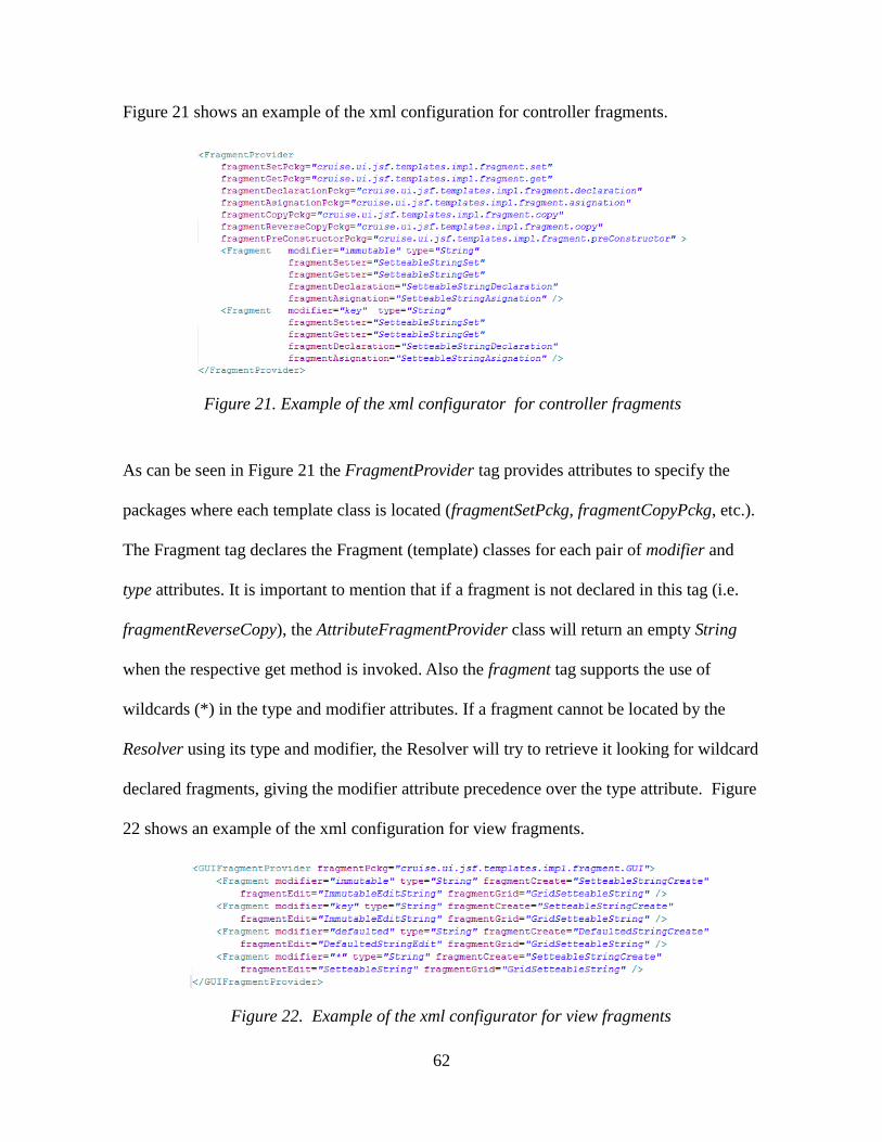
62
Figure 21 shows an example of the xml configuration for controller fragments.
As can be seen in Figure 21 the FragmentProvider tag provides attributes to specify the
packages where each template class is located (fragmentSetPckg, fragmentCopyPckg, etc.).
The Fragment tag declares the Fragment (template) classes for each pair of modifier and
type attributes. It is important to mention that if a fragment is not declared in this tag (i.e.
fragmentReverseCopy), the AttributeFragmentProvider class will return an empty String
when the respective get method is invoked. Also the fragment tag supports the use of
wildcards (*) in the type and modifier attributes. If a fragment cannot be located by the
Resolver using its type and modifier, the Resolver will try to retrieve it looking for wildcard
declared fragments, giving the modifier attribute precedence over the type attribute. Figure
22 shows an example of the xml configuration for view fragments.
Figure 21. Example of the xml configurator for controller fragments
Figure 22. Example of the xml configurator for view fragments

63
4.3.1.6 BackingObject
The BackingObject encloses the data required to generate a complete CRUD for a specific
class declared in the Umple model. It also inspects the respective UmpleClass object, the
related UmpleVariable and AssociationVariable objects and other Umple objects to gather
the information required to generate both, the view and the controller objects. This class
also provides some utility methods to determine if an attribute is a key (isKey()), if the
class has a parent class (hasParent()), and other methods to get the fragment provider, to
get the related DAO table, etc. BackingObject is the transfer object used by different UIGU
objects; BackingObject's methods like getClasses(), getSingletons(), getAllClasses(), etc. in
UIGenerator return Collections of BackingObject instances. Also the getClassMap()
method in UIProvider is a Map with class names as keys and BackingObject instances as
values. Table 13 shows BackingObject‘s most important methods and their purposes.

64
Method
Arguments Return Purpose
getKeysAttributes List<AttributeVariable> Returns a List of the attributes marked as
keys.
isKey AttributeVariable boolean Given an attribute it returns true if the attribute is a key field of the class, and
false otherwise.
getClassName String Returns the class name
getImports List<String> Returns all dependencies required for
the class.
getPackageName String Returns the class package (equal to the declared namespace)
getConstructorSignature String Returns the constructor signature for the
respective Umple generated domain object.
getAttVariables List<AttributeVariable> Returns all declared attributes in the
Umple model, but not the keys.
getFragmentProvider UIProvider Returns a reference to the UIProvider.
getDAOTable String Use to determine wich DAO handles the
respective Umple generated domain object.
getManyToOneAssociations List<AssociationVariable> Returns the 1--m Associations to normal
classes, with m>1.
getConstructorOneAsociations List<AssociationVariable> Returns the x--1 Associations to normal
classes, where x is any valid multiplicity.
getZeroOrOneAsociations List<AssociationVariable> Returns the x—0..1 Associations to normal classes, where x is any valid
multiplicity.
getZeroManyToOptionalAssociations List<AssociationVariable> Returns the 0..m—0..m and the 0..1—0..m Associations to normal classes,
where x is any valid multiplicity and
m>1.
getNManyToOptionalAssociations List<AssociationVariable> Returns the 0..m—n..m and the 0..1—
n..m Associations to normal classes,
where x is any valid multiplicity, m>1 and n>0.
getMandatoryToSingletonAssociations List<AssociationVariable> Returns the x--1 Associations to
singleton classes, where x is any valid multiplicity.
getOptionalToSingletonAssociations List<AssociationVariable> Returns the 0..m—0..m and the 0..1—0..m Associations to singleton classes,
where x is any valid multiplicity and
m>1.
getManyToOneSingletonAssociations List<AssociationVariable> Returns the x--1 Associations to
singleton classes, where x is any valid
multiplicity.
Table 13. BackingObject's important methods
BackingObject has only one public constructor which takes an UmpleClass as parameter. At
construction time, BackingObject resolves the attributes and associations inherited from
parent classes, and classifies all associations following the rules listed in Table 14.

65
Criteria
Returned By
Classes that require an instance of the
current objet to be constructed
getManyToOneAssociations
getManyToOneSingletonAssociations
The current object requires (mandatory) an
instance of the associated object at
construction time
getConstructorOneAsociations
getMandatoryToSingletonAssociations
The current object can be linked (optionally)
to an instance of the associated object at
construction time
getZeroOrOneAsociations
getOptionalToSingletonAssociations
Optional multiple associations not linked in
the constructor
getZeroManyToOptionalAssociations
Optional multiple associations linked in the
constructor
getNManyToOptionalAssociations
Table 14. Association classification
4.3.1.7 Other classes and interfaces
GUIModel contains several utility classes, some of them were created to modularize the
code and other ones just to join repetitive tasks. In the first group, it is important to mention
the AssociationResolver class which is used by BackingObject to classify the associations;
in the second group, the ClassWriter class provides several methods related with files and
directories operations (copy, write, delete, etc.).
GeneratorException is a RuntimeException thrown if something goes wrong in the
generation process.
4.3.2 GUIGenerator
In Section 4.2, we split the generation responsibilities into three levels. Having GUIModel
as the upper layer, and GUIGenerator in charge of middle layer responsibilities. While
GUIModel gathers common functions for different programming languages and UI

66
Frameworks, GUIGenerator joins common tasks for a specific programming language.
This means that in order to create a Complete GUIGenerator for a different programming
language, a new GUIGenerator has to be written, but it has to implement the interfaces
declared in GUIModel. To recap GUIGenerator‘s two main tasks are:
Provide default implementation classes for the interfaces declared in the upper level.
Each class has to contain common code and routines in order to be extended by
classes in the lower level.
Provide a mechanism for registering and tracking (persistence) the objects created
by the user.
We develop a GUIGenerator for the Java programming language (from now on referred
simply as GUIGenerator). Figure 23 shows GUIGenerator‘s class diagram.
For the first task, GUIGenerator provides the AbstractProvider and the
AbstractUIGenerator classes. These classes implement the GUIModel’s UIProvider and
UIGenerator interfaces respectively.
AbstractUIGenerator implements the UIGenerator interface. AbstractUIGenerator
classifies the classes declared in the Umple model into the three main categories:
singeltons, classes (normal) and allClasses (singletons + normal).
The AbstractProvider class uses the Resolver classes declared in GUIModel to provide
implementation to all get fragment related methods. This class declares references to the

67
UIGenerator‘s classes classifications (allClasses, classes, singletons) and the ClassMap. It
also has a reference to the Properties declared in the UmpleProject.xml.
A Concrete UIProvider should extend these abstract classes to add methods and utilities for
a specific UI framework.
GUIGenerator implements a factory pattern (through UIFactory) to be able to instantiate
different Concrete UIProviders. The implemented layer is based on the Generic Data
Access Objects strategy proposed by Hibernate [32]. Figure 24 shows the generated DAO
layer for a specific Umple model (see Appendix III, Example 1).
Figure 23. GUIGenerator's class diagram

68
For the second task, GUIGenerator provides a set of templates to create (using
UmpleProject.xml) a complete DAO layer, following the DAO+AbstractFactory approach.
UIGU‘s generated DAO layer contains a concrete DAO implementation for both the factory
Figure 24. Generated DAO class diagram and Umple model (upper left corner).

69
and the DAO itself (FakeDAOFactory and GenericFakeDAO respectively). The
FakeDaoFactory provides methods to access the Concrete DAOs (through the respective
DAO interface). GenericFakeDAO class is a generic class with the object or entity to be
persisted (T) and the key that identifies the object (PK) as type parameters.
GenericFakeDAO mimics a regular database DAO. However, the objects are not persisted
at all; they are referenced in a HashMap using the helper classes ObjectRepository and
Session. The ObjectRepository class maintains an object structure where each Entity
(domain object) is a ―Table‖ (implemented as a HashMap); When isA relations are
declared, the DAO layer implements the ―One inheritance path, one table‖ pattern, which
reduces each path in an inheritance tree to a single table [17].
To identify the domain objects, UIGU generates Key classes (the PK parameterized type in
GenericFakeDAO). These classes implement the equals and hashcode methods with the
attributes declared as keys in the Umple model. Currently, Umple does not support key
definitions using attributes of parent classes. This limitation prevents the inheritance of key
classes.
DAO + AbstractFactory pattern was adopted for flexibility reasons. In this way the user
can create his own implementation of GenericDAO, the DAOs interfaces, and DAOFactory,
in order to be able to swap the repository (for instance to a real database) without changing
any other UIGU generated code.

70
4.3.3 JSF Provider
To provide a proof of UIGU‘s concept we develop a first UIProvider for the JSF
technology. This provider was created using Jboss RichFaces[34]. RichFaces is a
component library for JSF and an advanced framework for easily integrating AJAX
Figure 25. JSFProvider’s class diagram

71
capabilities into business applications. This AJAX support allows the creation of advanced
UI interfaces for web applications. Figure 25 shows the JSFProvider’s class diagram.
The JSFProvider inherits the GUIGenerator abstract classes (AbstractProvider,
AbstractGenerator, and AbstractValidationProvider) to create concrete implementations
(JSFProvider, JSFGenerator, and JSFValidationProvider respectively), and to declare a
UIFactory to follow GUIGenerator’s factory strategy.
In Section 4.3.1.5 we talked about the GUIConfigurator.xml and AttributteConfigurator.xml
files; we explained that these files are used to declare the UI fragments for several CRUD
operations/steps. The UIProvider has to provide those files and to pass their file paths to the
AbstractProvider constructor. Since each UIProvider can declare different configuration
files to allow the user to customize the generator‘s output, the JSFProvider uses the
properties ATTRIBUTE_CONFIGURATOR and GUI_ATTRIBUTE_CONFIGURATOR to
declare the required file paths. These properties have to be declared in the properties
section of UmpleProject.xml. Figure 26 shows an example.
Chapter 5, Using UIGU, will discuss more about the configuration of the JSFProvider.
Figure 25 shows that one of the main responsibilities of each concrete UIProvider is the
Figure 26. UmpleProject.xml, declaring the attribute configurator xml files.

72
generation of both view code and controller code to support associations. This distribution
of responsibilities responds to the fact that each UI Framework has different navigation
models (going from one view, also known as screen, to another), making difficult a general
classification of the required fragments. While the AbstractProvider class (from
GUIGenerator) provides methods to access the attribute fragments and the ClassMap, the
JSFProvider class declares the required methods to get the association fragments. Before
talking about these fragments, we are going to explain the JSFProvider’s generated UI.
4.3.3.1 Skeletons
An overview of JET Technology was explained in Section 2.5.4. JET templates are
compiled into Java classes with a generate(Object) method with String as return type.
However UIGU requires that all fragments must implement the IGenerator interface (see
section 4.3.1.1). This implies that the default JET generated classes have to be customized.
Skeletons are JET‘s mechanisms to do such customization. Figure 27 shows the
JSFProvider‘s skeleton and a fragment declaring this skeleton.
Figure 27. IGenerator skeleton (left), skeleton declaration (right)
4.3.3.2 The Generated UI for Attributes
In Sections 2.2.2 and 2.2.3 we described the subset of attributes and associations supported
by UIGU. To determine how to render an attribute, UIGU uses the FragmentResolver class
to return the required fragment for an attribute regarding its type and modifier.

73
To render attributes the following general considerations apply:
If an attribute is declared with an initial value, this value cannot be modified in the
Create operation.
Since a defaulted attribute must be declared with an initial value, the attribute value
can only be modified in the Update (edit) operation. An icon will be displayed to
allow the user to return to the default (initial) value.
Internal attributes will only be displayed in the create operation if and only if an
initial value was not indicated.
An icon will indicate if an attribute is part of the key definition.
Once an instance is created, Key attributes cannot be modified.
Figure 28 shows the Umple model for a single class with settable attributes for all
supported types.
To obtain the required fragment the caller has to invoke the appropriate get method in the
JSFProvider, passing the AttributeVariable and the parameters . Figure 29 shows how a
fragment can be retrieved using the getFragmentProvider() method in the BackingObject
class. Here, attVar is a reference to an AttributeVariable and the String
"a"+bckObject.getClassName() is a parameter to be replaced in the #1# holder.

74
Table 15 shows the template fragments and the generated UI components for the code listed
in Figure 28.
Figure 28. Umple Model showing settable attributes
UIProvider prov= bckObject.getFragmentProvider();
String codeFgm=prov.getGUICreateFragment(attVar, "a"+bckObject.getClassName());
Figure 29. Calling the fragment provider to get a create fragment

75
Create Update Grid
Fragment UI no init value Fragment UI Fragment UI UI init value
String
<h:outputText value="<%=attVar.getUpperCaseName()%>"
/>
<% if (attVar.getValue()==null){ %>
<h:inputText
value="#{#1#Bean.<%=attVar.getName()%>}"
></h:inputText>
<% } else {%>
<h:outputText value=<%=attVar.getValue()%>
style="text-align:right;" ></h:outputText> <%}%>
<h:outputText
value="<%=attVar.getUpperCaseName()%>" />
<h:inputText
value="#{#1#Bean.<%=attVar.getName()%>}" />
<f:facet name="header">
<%=attVar.getUpperCaseName()%>
</f:facet>
<h:outputText
value="#{#1#.<%=attVar.getName()%>}" >
</h:outputText>
Boolean
<h:outputText value="<%=attVar.getUpperCaseName()%>"
/>
<% if (attVar.getValue()==null){ %>
<h:selectBooleanCheckbox
value="#{#1#Bean.<%=attVar.getName()%>}" />
<% } else {%>
<h:selectBooleanCheckbox
value="#{#1#Bean.initial<%=attVar.getUpperCaseName()
%>}" disabled="true" /> <%}%>
<h:outputText
value="<%=attVar.getUpperCaseName()%>" />
<h:selectBooleanCheckbox
value="#{#1#Bean.<%=attVar.getName()%>}" />
<f:facet
name="header"><%=attVar.getUpperCaseName()%>
</f:facet>
<h:selectBooleanCheckbox
value="#{#1#.<%=attVar.getName()%>}"
readonly="true" disabled="true"/>
Integer
<% if (attVar.getValue()==null){ %>
<h:inputText
value="#{#1#Bean.<%=attVar.getName()%>}" >
<f:converter converterId="javax.faces.Integer" />
</h:inputText>
<% } else {%>
<h:outputText
value="#{#1#Bean.initial<%=attVar.getUpperCaseName()
%>}" style="text-align:right;" >
<f:converter converterId="javax.faces.Integer" />
</h:outputText> <%}%>
<h:outputText
value="<%=attVar.getUpperCaseName()%>" />
<h:inputText
value="#{#1#Bean.<%=attVar.getName()%>}" >
<f:converter
converterId="javax.faces.Integer" />
</h:inputText>
<h:outputText
value="#{#1#.<%=attVar.getName()%>}" >
<f:converter converterId="javax.faces.Integer"
/>
</h:outputText>
Double
<h:outputText value="<%=attVar.getUpperCaseName()%>"
/>
<% if (attVar.getValue()==null){ %>
<h:inputText
value="#{#1#Bean.<%=attVar.getName()%>}" >
<f:converter converterId="javax.faces.Double" />
</h:inputText>
<% } else {%>
<h:outputText
value="#{#1#Bean.initial<%=attVar.getUpperCaseName()
%>}" style="text-align:right;" >
<f:converter converterId="javax.faces.Double" />
</h:outputText> <%}%>
<h:outputText
value="<%=attVar.getUpperCaseName()%>" />
<h:inputText
value="#{#1#Bean.<%=attVar.getName()%>}" >
<f:converter
converterId="javax.faces.Double" />
</h:inputText>
<f:facet
name="header"><%=attVar.getUpperCaseName()%>
</f:facet>
<h:outputText
value="#{#1#.<%=attVar.getName()%>}" >
<f:converter converterId="javax.faces.Double" />
</h:outputText>
Date
<h:outputText value="<%=attVar.getUpperCaseName()%>"
/>
<% if (attVar.getValue()==null){ %>
<rich:calendar
value="#{#1#Bean.<%=attVar.getName()%>}"
popup="true" datePattern="yyyy-MM-dd"
showApplyButton="false" cellWidth="24px"
cellHeight="22px" style="width:200px" />
<% } else {%>
<h:outputText
value="#{#1#Bean.initial<%=attVar.getUpperCaseName()
%>}" style="text-align:right;" >
<f:convertDateTime type="date" pattern="yyyy-MM-
dd"/>
</h:outputText> <%}%>
<h:outputText
value="<%=attVar.getUpperCaseName()%>" />
<rich:calendar
value="#{#1#Bean.<%=attVar.getName()%>}"
popup="true" datePattern="yyyy-MM-dd"
showApplyButton="false" cellWidth="24px"
cellHeight="22px" style="width:200px" />
<f:facet
name="header"><%=attVar.getUpperCaseName()%>
</f:facet>
<h:outputText
value="#{#1#.<%=attVar.getName()%>}" >
<f:convertDateTime type="date" pattern="yyyy-MM-
dd"/>
</h:outputText>
Time
<h:outputText value="<%=attVar.getUpperCaseName()%>
" />
<% if (attVar.getValue()==null){ %>
<h:panelGrid columns="3">
<h:selectOneMenu value="#{#1#Bean.<%=
attVar.getName()+"Hour"%>}">
<f:selectItems value="#{timeBean.hours}" />
</h:selectOneMenu>
<h:outputText value=":" />
<h:selectOneMenu value="#{#1#Bean.<%=
attVar.getName()+"Minute"%>}">
<f:selectItems value="#{timeBean.minutes}" />
</h:selectOneMenu>
</h:panelGrid>
<% } else { %>
<h:outputText
value="#{#1#Bean.initial<%=attVar.getUpperCaseName()
%>}">
<f:convertDateTime pattern="hh:mm" />
</h:outputText> <% } %>
<h:outputText
value="<%=attVar.getUpperCaseName()%> " />
<h:panelGrid columns="3">
<h:selectOneMenu value="#{#1#Bean.<%=
attVar.getName()+"Hour"%>}">
<f:selectItems value="#{timeBean.hours}" />
</h:selectOneMenu>
<h:outputText value=":" />
<h:selectOneMenu value="#{#1#Bean.<%=
attVar.getName()+"Minute"%>}">
<f:selectItems value="#{timeBean.minutes}"
/>
</h:selectOneMenu>
</h:panelGrid>
<f:facet
name="header"><%=attVar.getUpperCaseName()%>
</f:facet>
<h:outputText
value="#{#1#.<%=attVar.getName()%>}">
<f:convertDateTime pattern="hh:mm" />
</h:outputText>
Table 15. Template fragments and generated UI components for the model listed on Figure 28 (settable attributes)

76
Figure 30 shows the generated UI components for defaulted attributes. The user can click
on the green icon to roll back the attribute value to the defaulted (initial) value. This icon
fires an AJAX call to return the default value from the controller.
<h:outputText value="<%=attVar.getUpperCaseName()%>" />
<h:panelGrid columns="2">
<rich:calendar value="#{#1#Bean.<%=attVar.getName()%>}" popup="true"
id="<%=attVar.getUpperCaseName()%>#{uniqueId}"
datePattern="yyyy-MM-dd" showApplyButton="false"
cellWidth="24px"
cellHeight="22px" style="width:200px" />
<a4j:commandLink
action="#{#1#Bean.resetToDefaulted<%=attVar.getUpperCaseName()%>}"
reRender="<%=attVar.getUpperCaseName()%>#{uniqueId}">
<h:graphicImage value="/images/icons/reload.png" style="border:0" />
</a4j:commandLink>
</h:panelGrid>
Figure 30. Generated UI for defaulted attributes. Template fragment (left). Generated UI
(right)
Key attributes behave in the same way as immutable attributes. To indicate that an attribute
is part of the key definition, UIGU renders a key icon next to the attribute UI component.
Figure 31 shows the generated UI for key attributes.
Figure 31. Generated UI components for key attributes. Create (left) and Update (right)
operations
4.3.3.3 The Generated UI for Associations
In Section 4.3.1.6 we classified the associations (Table 14). The classification was made
using three criteria:
Multiplicity
Mandatory/Optional
Normal class/Singleton

77
JSFProvider contains methods to obtain the corresponding fragments for each type of
association. These fragments are divided into two categories according to the code required
to associate an object (or objects) to a class:
Form Fragments: Code required to launch a window with the appropriate actions to
select (in some cases create) the object (or objects) to be linked with the instance
being created or updated.
Panel Fragments: A window with the components required to select (in some cases
create) the object (or objects) to be linked.
In this way, a Form fragment is the code that launches a Panel Fragment. Table 16 shows
association classification and the key aspects of the generated UI.
Criteria
Returned By UI
Classes that require an
instance of the current
objet to be constructed
getManyToOneAssociations
getManyToOneSingletonAssociations
The launched window provides the
functionality to create, update and
delete the objects to be associated.
Since these objects require an
instance of the current object, the link
to launch that window is only visible
in the Update operation.
The current object
require (mandatory) an
instance of the associated
object at construction
time
getConstructorOneAsociations
getMandatoryToSingletonAssociations
The launched window provides the
functionality to select the object to be
associated with a list of objects
already created.
The current object can
be linked (optionally) to
an instance of the
associated object at
construction time
getZeroOrOneAsociations
getOptionalToSingletonAssociations
The launched window provides the
functionality to select the object to be
associated with a list of objects
already created.
Optional multiple
associations not linked
in the constructor
getZeroManyToOptionalAssociations
The launched window provides the
functionality to select (and unselect) a
collection of objects to be associated
from a list of objects already created.
Optional multiple
associations linked in
the constructor
getNManyToOptionalAssociations The launched window provides the
functionality to select (and unselect) a
collection of objects to be associated
from a list of objects already created.
Table 16. Classification of associations and generated UI.
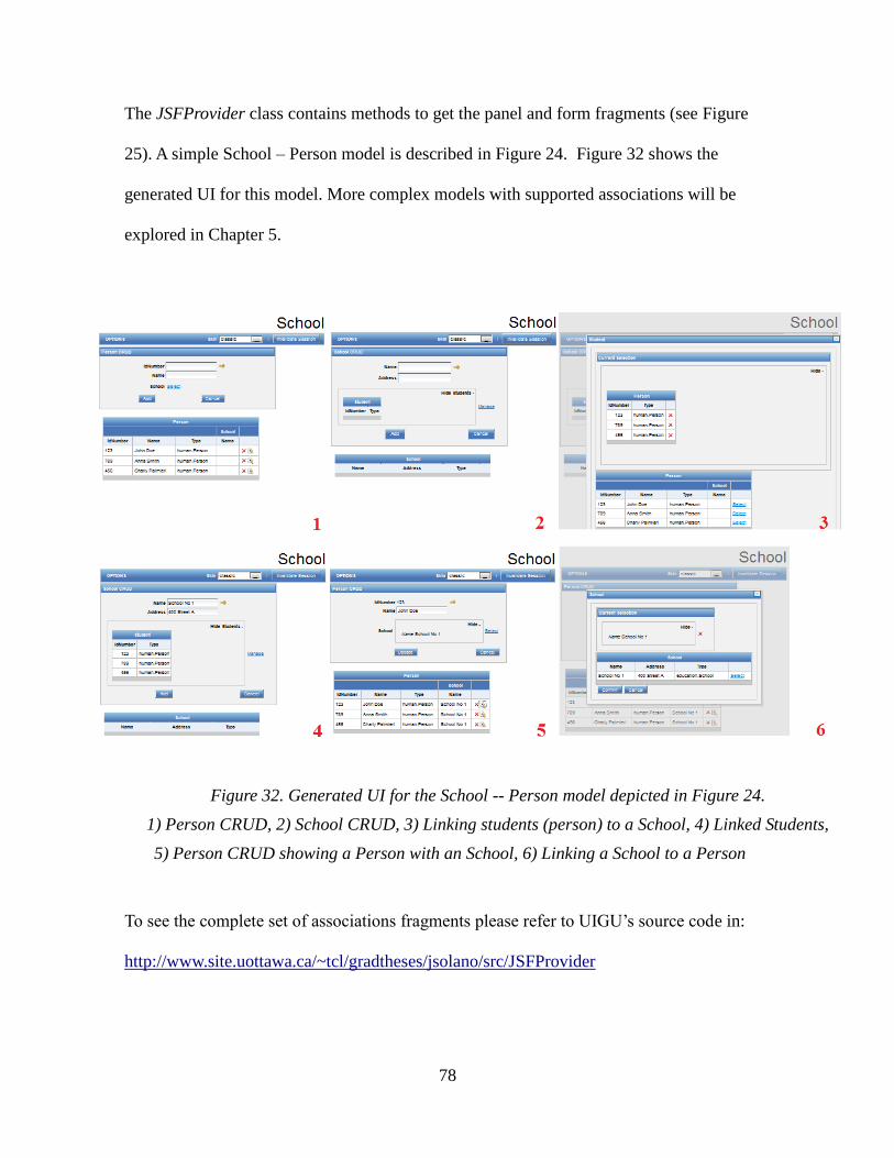
78
The JSFProvider class contains methods to get the panel and form fragments (see Figure
25). A simple School – Person model is described in Figure 24. Figure 32 shows the
generated UI for this model. More complex models with supported associations will be
explored in Chapter 5.
To see the complete set of associations fragments please refer to UIGU‘s source code in:
http://www.site.uottawa.ca/~tcl/gradtheses/jsolano/src/JSFProvider
Figure 32. Generated UI for the School -- Person model depicted in Figure 24.
1) Person CRUD, 2) School CRUD, 3) Linking students (person) to a School, 4) Linked Students,
5) Person CRUD showing a Person with an School, 6) Linking a School to a Person

79
4.3.3.4 Controller Fragments
Section 4.1.2 classifies the fragments into two categories: View fragments and controller
fragments. Sections 4.3.3.2 and 4.3.3.3 were focused on View fragments (fragments that
render an UI component). Controller fragments are these code snippets returned by the
methods declared in Table 5. As well as View fragments, Controller fragments have to
implement the IGenerator interface in order to be instantiated by FragmentLoader. These
fragments are declared in the AttributeConfigurator.xml, The path to this file has to be
configured in UmpleProject.xml adding the ATTRIBUTE_CONFIGURATOR property in
the properties section. Table 17 shows a sample set of Controller fragments for a settable
boolean attribute.
To see the complete set of Controller fragments please refer to UIGU‘s source code in:
http://www.site.uottawa.ca/~tcl/gradtheses/jsolano/src/JSFProvider

80
Method Fragment
getSetFragment public void set<%= attVar.getUpperCaseName()%>(
<%= attVar.getType()%> <%=attVar.getName()%>) {
this.<%= "a"+attVar.getUpperCaseName()%> = <%= attVar.getName()%>;
}
getGetFragment public <%= attVar.getType()%> get<%= attVar.getUpperCaseName()%>() {
return <%="a"+ attVar.getUpperCaseName()%>;
}
<% if (attVar.getValue()!=null){ %>
public <%= attVar.getType()%> getInitial<%= attVar.getUpperCaseName()%>()
{
return <%=attVar.getValue()%>;
}
<% }%>
getDeclarationFragment private <%= attVar.getType()%>
<%= "a"+attVar.getUpperCaseName()%>= <%= attVar.getValue()%>;
getAsignationFragment <%="a"+ attVar.getUpperCaseName()%> = #1#;
getCopyFragment #1#.set<%= attVar.getUpperCaseName()%>(<%="this.a"+
attVar.getUpperCaseName()%>);
getPreConstructorFragment
getReverseCopyFragment this.a<%=attVar.getUpperCaseName()%>=#1#.get<%=
attVar.getUpperCaseName()%>();
Table 17. Controller fragments for a settable boolean attribute. attVar is an
AttributeVariable instance
Figure 33 shows how a fragment can be retrieved using the getFragmentProvider() method
in the BackingObject class.
4.3.3.5 Main Templates
A main template is a template that calls many template fragments. In this way, a main
template is a composition of fragments. Each main template is used to generate a
GenerationUnit, which is an actual application object like a class, a web page, a
configuration file, etc.
The JSFProvider component requires several main templates to generate the UI
UIProvider prov= bckObject.getFragmentProvider();
String codeFgm=prov.getSetFragment(attVar);
Figure 33.Getting a controller fragment; attVar is an AtributeVariable.

81
application. Generated web pages use Facelets technology [35] to compose views allowing
the reuse of xhtml pages in different views (i.e. the grid can be shown in the bottom of the
page to list the created objects, or in a pop-up to associate an object to another). Table 18
shows the templates (package cruise.ui.jsf.templates.impl.GUI) required to generate the
web (xhtml) pages (GUI objects). Table 10 describes ParameterType’s values and their
outputs.

82
Template Purpose ParameterType
Common Common declarations: Menu, Style classes, resource
bundles.
Output: Common.xhtml
ALL_CLASSES
Home Application‘s Entry point.
Output: Home.xhtml
NONE
Grid A simple grid showing the objects created in the system
for a given type. It provides the icons to select (for
update) and delete the object.
Output: Grid.xhtml
NORMAL_CLASS_BY_CLASS
BaseInsertable This template contains the form with the fields and
associations links to instantiate new objects for a single
class. It includes the related Grid (generated using the
grid template), other grids (for associations) and other
Insertable.xhtml generated pages (for associations).
Output: <ClassType>Insetable.xhtml
NORMAL_CLASS_BY_CLASS
BaseMain Generates the entry point for a specific CRUD.
This template includes Common.xhtml and the related
Insertable.xhtml page.
Output: <ClassType>Main.xhtml
NORMAL_CLASS_BY_CLASS
GridSelectOne A grid with an icon to select an object (for associations).
It has a panel to show the current selection. It includes
the related Grid.xhtml.
Output: GridSelectOne.xhtml
NORMAL_CLASS_BY_CLASS
GridSelectMany A grid with an icon to select multiple objects (for
associations). It has a panel to show the current
selection. It includes the related Grid.xhtml.
Output: GridSelectMany.xhtml
NORMAL_CLASS_BY_CLASS
BaseInsertableSingleton This template generates a form to maintain a singleton
class. This template includes different Grid.xhmtl
pages (for associations) and Insertable.xhtml generated
pages (for associations)
Output: <ClassType>Insetable.xhtml
SINGLETON_CLASS_BY_CLASS
Table 18. GUI Main Templates
As we mentioned in Section 2.7.1, JSF requires a set of special objects called
BackingBeans to provide properties and functions to the views (i.e. when a calendar shows
a Date in the UI, the BackingBean has a Calendar attribute with the date showed in the

83
view). Each different view should have a BackingBean to work properly. While View
fragments are used by the GUI Main templates, Controller fragments (package
cruise.ui.jsf.templates.impl) are consumed by Controller Main templates. Table 19 shows
the Controller main templates required to generate the BackingBeans and other utility
classes.
Template Purpose ParameterType
BckBean This template generates a BackingBean for a given
class. The generated java class contains the logic to
interact with the DAO (model) layer, and with Java
objects to map attributes and associations. It also
contains actions to navigate between views.
Output: <ClassType>Bean.java
NORMAL_CLASS_BY_CLASS
BckBeanSingleton This template generates a BackingBean for a given
singleton class. The generated java class contains
the logic to interact with the DAO (model) layer,
and with Java objects to map associations. It also
contains actions to navigate between views.
Output: <ClassType>Bean.java
NORMAL_CLASS_BY_CLASS
BeanLinker This template generates the BeanLinker class. This
class is a helper class that serves as a container to
associate objects. When a view calls another view
to associate an object, the caller sends and empty
BeanLinker (just with the association name), and
the destination class sets the associate instance (or
collection of instances) in the BeanLinker.
Output: BeanLinker.java
NONE
MainBean This template generates a BackingBean with a
session scope (this is, there is only one instance per
user session and it is ―alive‖ until the session
expires. This class provides methods to get the
DAO factory and to navigate between CRUDs.
Output: MainBean.java
NONE
PageFlowUtils This template generates a BackingBean with a
session scope. This class contains helper methods to
provide a context to each view and to support the
communication (navigation) between views. The
following section will discuss the navigation model,
Output: PageFlowUtils.java
NONE
Table 19. Controller main templates
A JSF application requires at least two configuration files: faces-config.xml and web.xml.

84
The faces-config.xml contains information about the existing views, the navigation
(navigation rules), declared BackingBeans, validation converters, etc. It is possible to
define more than one faces-config.xml, this division is usually done for modularization
purposes. Figure 34 is a graphical representation of the navigation rules declared in the
generated faces-config.xml for the School – Person model described in Figure 24.
Figure 34. faces-config.xml's navigation rules declared in the School--Person model
The faces-config template (package cruise.ui.jsf.templates.impl.GUI.config) generates the
required faces-config.xml; it takes ALL_CLASSES as ParameterType.
The Application entry point, security constrains, parameters, and JSF configuration are
declared in web.xml. The web template (package cruise.ui.jsf.templates.impl.GUI.config)
generates the required web.xml; it takes NONE as ParameterType.
4.3.3.6 Navigation model
In order to create the application, it was necessary to choose an appropriate scope for

85
generated backing beans. In Section 2.7.1 we discussed backing bean scopes, but since the
generated JSF is a Rich Internet Application (RIA) with Ajax as mechanism to interact with
the server, and a user can define a model with reflexive associations (i.e. 0..1 A -- * A) or
cyclical associations (i.e. 0..1 A-- * B, * B -- * C and 0..1 C -- A), some issues about
navigation have to be analyzed.
Scopes None and Application are not suitable; the former, because our backing beans have
to be instantiated automatically when a user launches a CRUD, and the latter because if the
backing bean is shared between multiple users the data introduced by one of them will
affect the data of the other users.
Request scope also has some drawbacks:
The lifespan of the backing beans is limited to a request/response cycle. This means
that different requests are served by different instances. String, Integer, Boolean and
types with appropriate converters (like Date and Float) are automatically copied
from one instance to the next. However, other objects are not copied. For instance,
in our simple School – Person model, the PersonBean (Person Backing Bean) has a
School attribute to maintain a reference to the selected school; this reference is
going to be nullified in the next request.
Ajax performs many requests underneath without reloading the UI, but each request
instantiates new request scoped backing beans. If the user clicks on an association
link and selects an object to create an association, the respective backing bean will
have a reference to that object; however, if the user clicks in a different association
86
link to create another association, the first reference is nullified because the first
reference is not copied and each action (each click on the links) will be served by a
different request.
On the other hand, Session scope backing beans will keep the references between different
requests, but this scope has an undesired side effect. If the model contains reflective or
cyclical associations in the generated UI, the user will launch from one (initial) view
another views (through associations) that eventually will launch the initial view
(referenced here as the current view). Since both the initial and the current view use the
same backing bean, the data of the initial view will be displayed in the current view, and the
modifications performed in the current view will update the values in the initial one. This is
not desired because probably both the initial and the current view are being displayed to
manage different associations.
The implemented solution uses a combination of the session and request scope. All backing
beans are request scoped, but each view runs in its own context to store the objects that are
not copied automatically. The contexts are stored in a stack (called PageFlow) available
through the session context. When a CRUD is launched, the PageFlow is initialized with
the context of the initial view. If the initial view calls another view, a new context is created
and stored in the stack. Finally, when a view is closed its context is removed from the stack.
The object used as a context is an instance of the BeanLinker class. Figure 35 shows the
navigation model when a Person is linked to a School in the Person – School model.
Section 4.3.5 will explain architecture of the generated application.

87
1
Figure 35. Sample navigation model for the Person -- School model.
Looking at home view. 1) Person CRUD is launched, 2) Person view invokes school view to associate a School instance to
a Person instance (student role), 3) School association is done, 4) Returning to home view
Note the Stack (PageFlow) with the respective context for each step.

88
4.3.4 UIGU Generation Proccess
The UIGU class is the entry point to UIGU‘s generation. The classes UIGenerator,
UIFactory, UmpleProjectWriter and UIProvider have an initialize method that must be
invoked before any other method (otherwise a cruise.exception.GeneratorException is
thrown). This strategy was adopted to break some dependencies between these classes, i.e.
UmpleProjectWriter reads the declared properties (in UmpleProject.xml), but UIFactory
requires these properties to instantiate the UIGenerator, while UmpleProjectWriter needs
an UIGenerator to generate the code. Figure 37 shows the generation process in a
sequence diagram. UmpleSystem and UmpleFile are Umple core classes (see Figure 10).
Unmarshaller and UmpleProject are Jaxb classes to read the configuration file.
4.3.5 Architecture of the generated application
As we discussed in Section 2.6.1 the generated application is an implementation of the
MVC pattern. In the MVC application output by UIGU, the model layer is composed of
Umple-generated domain objects and UIGU-generated DAOs. Controller layer
responsibilities are implemented by backing beans, and the xhtml (web) pages are part of
the View layer (see Figure 36).
Figure 36. MVC responsabilities

89
Figure 37. UIGU generation process

90
In addition to the MVC classes, the utility classes BeanLinker, PageFlowUtils and
Figure 38. School -- Person model. Generated application's class diagram

91
MainBean are also generated (see Table 19). In this chapter we used a simple School –
Person model (Figure 24) to illustrate many UIGU‘s features. Figure 38 shows the
generated application‘s class diagram
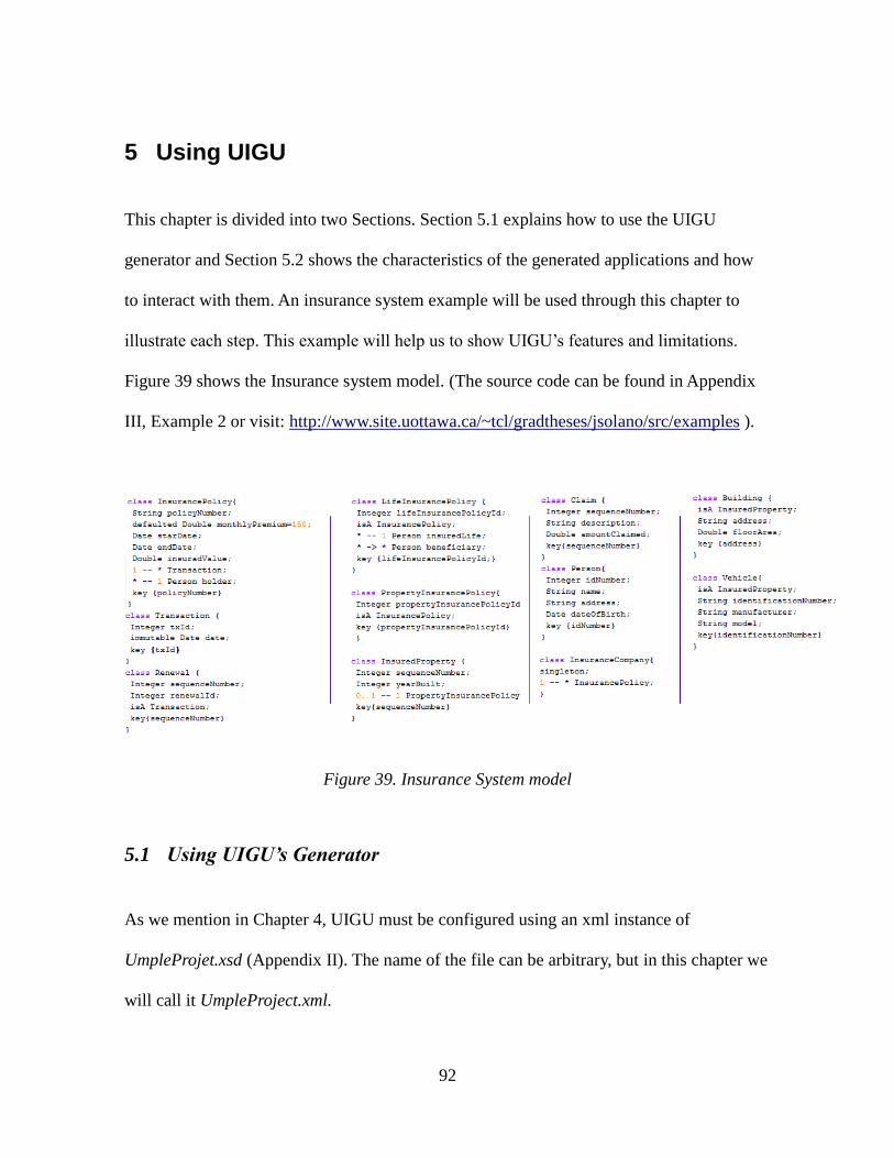
92
5 Using UIGU
This chapter is divided into two Sections. Section 5.1 explains how to use the UIGU
generator and Section 5.2 shows the characteristics of the generated applications and how
to interact with them. An insurance system example will be used through this chapter to
illustrate each step. This example will help us to show UIGU‘s features and limitations.
Figure 39 shows the Insurance system model. (The source code can be found in Appendix
III, Example 2 or visit: http://www.site.uottawa.ca/~tcl/gradtheses/jsolano/src/examples ).
Figure 39. Insurance System model
5.1 Using UIGU’s Generator
As we mention in Chapter 4, UIGU must be configured using an xml instance of
UmpleProjet.xsd (Appendix II). The name of the file can be arbitrary, but in this chapter we
will call it UmpleProject.xml.
93
5.1.1 Configuring UIGU
For a defined UIProvider, the UmpleProject.xml can be either reused with few
modifications or reused but overwriting some attributes in the command line. In Section
4.3.1.3, we described the different sections and attributes of the configuration file. If the
user wants to create an UmpleProject.xml specific for one defined model, the required
modifications are related to the location of the required files to build the project, and the
paths to write the generated files. All locations (or paths) can be declared either as absolute
or relative to the current folder, unless indicated otherwise. Appendix IV contains a sample
xml file for the JSFProvider. The required modifications are:
UmpleProject tag
o OutputFolder: In this folder, the generated files are going to be
written/copied. If the folder does not exist, UIGU will create it. If the folder
is not empty, its content is going to be deleted before the generation process..
o UmpleFile: The location of the model to be generated. Since at the
beginning of the generation process the output folder‘s content is deleted,
this file cannot be in the same location declared in the output folder attribute.
o Name: The name of the project. This does not allow spaces. This name is
going to be used to identify the project. JSFProvider uses this attribute to
create a header in all xhtml pages and to declare the project in the web.xml
file.
o UIFactory: The class name of the factory object (it should extend
cruise.factory.UIFactory) declared by the UIProvider. It must contain the

94
package (e.g. cruise.ui.jsf.JSFFactory).
Properties: In this section several properties are declared, some of them are required
by the GUIModel and the remaining ones are required by the concrete UIProvider.
o UMPLE_FOLDER: The location where the domain objects have to be
moved, relative to OutputFolder. For the JSFProvider this value has to be
set to JavaSource.
o ATTRIBUTE_CONFIGURATOR: The location of the xml file with the
fragment configuration for the controller objects. This location should be
declared relative to the UIProvider folder (or Jar file). For the JSFProvider
this value has to be set to xml/AttributeConfigurator.xml.
o GUI_ATTRIBUTE_CONFIGURATOR: The location of the xml file with the
fragment configuration for the view objects. This location should be
declared relative to the UIProvider folder (or Jar file). For the JSFProvider
this value has to be set to xml/GUIAttributeConfigurator.xml.
o PROVIDER_JAR: If it is present, this property indicates to UIGU where is
the UIProvider Jar file. Otherwise, UIGU will try to locate this file using the
classpath.
Files: In this section all required files (including libraries) have to be copied to
specific locations inside the OutputFolder should be declared. It is important to
mention that each server contains some libraries by default, and to avoid duplication
(and therefore the JAR hell [36]) some of them have to be commented out, e.g.
UIGU was tested in JBoss versions 5.0.1 GA and 5.1.0 and Tomcat 6.0.24.

95
However, Tomcat requires some libraries that are build in JBoss. Figure 40 shows a
fragment of the UmpleProject.xml for the JSFProvider to illustrate this problem.
Figure 40. Files section fragment.
As we mentioned, for a defined UIProvider, only few changes are required to configure
UIGU. Table 20 resumes the required changes for the insurance system. These changes are
in the UmpleProject tag. From this point, we are going to assume that the Umple file is
called Insurance.ump and all files and folders are in the same location (Figure 41).
Figure 41. Insurance system required files
Attribute Value
UmpleFile Insurance.ump
Name Insurance_System
OutputFolder InsuranceApp
Table 20. Insurance System specific values
To reuse the UmpleProject.xml file with no changes the user can overwrite the attributes

96
defined in Table 20. The next section explains how to overwrite these attributes.
5.1.2 Running UIGU
To run UIGU it is necessary to declare GUIModel, GUIGenerator, UIProvider and Umple
jar files in the Java classpath. The class cruise.generator.UIGU is UIGU‘s main class. This
class is inside GUIGenerator.jar. Its main method takes four parameters; three of them are
the paths of the UmpleProject.xml file, the Umple file, and the output folder; the fourth one
is the project name. However to run UIGU, only the first parameter (UmpleProject.xml‘s
path) is mandatory. If the other three parameters are not provided, UIGU will use the values
declared in the UmpleProject.xml file. When the process is running, UIGU prints out the
filename of the file that is being generated or copied. Figure 42 shows the command
required to run UIGU and the console output (partial). UIGU requires Java 1.5 or higher to
run.
java -cp GUIModel.jar;JSFProvider.jar;GUIGenerator.jar cruise.generator.UIGU UmpleProject.xml
java -cp GUIModel.jar;JSFProvider.jar;GUIGenerator.jar cruise.generator.UIGU UmpleProject.xml Insurance.ump InsuranceApp
Insurance
Copying: C:\Insurance\Insurance.ump
Loading JAR: JSFProvider.jar
Generation process started
Writing: C:\Insurance\InsuranceApp\JavaSource\dao\insurance\core\ClaimDAO.java
Writing: C:\Insurance\InsuranceApp\JavaSource\dao\keys\insurance\core\ClaimKey.java
Writing: C:\Insurance\InsuranceApp\JavaSource\bundles\insurance\core\Claim.properties
Writing: C:\Insurance\InsuranceApp\JavaSource\web\insurance\core\ClaimBean.java
Writing: C:\Insurance\InsuranceApp\WebContent\pages\insurance\core\Claim\ClaimInsertable.xhtml
Writing: C:\Insurance\InsuranceApp\WebContent\pages\insurance\core\Claim\ClaimMain.xhtml
Writing: C:\Insurance\InsuranceApp\WebContent\pages\insurance\core\Claim\grid.xhtml
Writing: C:\Insurance\InsuranceApp\WebContent\pages\insurance\core\Claim\gridSelectMany.xhtml
Writing: C:\Insurance\InsuranceApp\WebContent\pages\insurance\core\gridSelectOne.xhtml
Writing: C:\Insurance\InsuranceApp\JavaSource\dao\insurance\core\PersonDAO.java
Writing: C:\Insurance\InsuranceApp\JavaSource\dao\keys\insurance\core\PersonKey.java
Writing: C:\Insurance\InsuranceApp\JavaSource\bundles\insurance\core\Person.properties
…
Generation SUCCESS
Figure 42. Running UIGU. Java command using the values declared in the xml file(top),
Java command overwriting attributes (middle), partial console's output (bottom)

97
5.1.3 Compiling UIGU
Since both Umple and UIGU outputs are source files, a compilation step is required. A JSF
application has to be compiled into a war (web application resource) file in order to be
deployed into a server. For the JSFProvider an apache ant [37] script (build.xml) is
provided. This script reads the xml file (UmpleProject.xml) passed as a parameter in the
command line to generate the compiled classes and the war file. Table 21 shows the tasks
defined in build.xml and their purpose.
Task Purpose Depends
run Run UIGU. It has the same effect as the java
command described in Figure 42
compile Compile all java classes into a bin directory inside
the OutputFolder location
run
war Generate a standard JEE war file run, compile
Table 21. Ant tasks
Figure 43 shows the command to run and compile UIGU using ant and the resulting files
and folders.
The generated war file (Insurance_Sytem.war) can be deployed in any JEE compliant
server.

98
5.2 Using the generated application
As an Umple UI generator, UIGU shares many of Umple‘s features and limitations. In
Section 2.2 we explained the Umple subset implemented by UIGU and also discussed the
minimum requirements to create an effective CRUD application. One of those requirements
is the use of keys for read operations. This implies that each class declared in an Umple
model has to declare key fields to allow UIGU to generate an effective CRUD. Umple
version (1.6.3), used to develop UIGU, supports key declarations; however, it does not
support the declaration of keys using inherited fields. In our insurance system example, the
policyNumber field is enough to identify an InsurancePolicy. This field is also inherited by
LifeInsurancePolicy and PropertyInsurancePolicy; however, these children classes cannot
ant -DxmlFile=UmpleProject.xml
ant -DxmlFile=UmpleProject.xml –DumpleFile=insurance.ump
–DoutputFolder=InsuranceApp –DprojectName=Insurance
Figure 43. Running UIGU. Ant command (top), resulting files and folders (bottom)

99
declare policyNumber in their key definitions. Repeating the policyNumber field in the
children classes leads to a compilation error, because Umple does not support attribute
overriding. This limitation forces the declaration of different key fields for children classes
(e.g. lifeInsurancePolicyId and propertyInsurancePolicyId). The ability to declare key
fields using inherited attributes is planned for future releases of Umple.
5.2.1 Deploying the generated application
Each server has different procedures to deploy a web application. As we mentioned, the
generated applications were tested in Tomcat 6, JBoss 5.0.1 and JBoss 5.1.0. In these
servers, different libraries have to be included in the war file (JBoss contains some of them
out of the box). See Files in Section 5.1.1.
To deploy the application in Tomcat, the war file has to be copied into the webapps folder.
To deploy it in JBoss, the war file has to be copied into the /server/default/deploy folder
instead.
5.2.2 Using the JSF web application
Our Insurance system contains definitions to show the Umple subset supported by UIGU.
Figure 44 shows the Insurance system class diagram1. The following subsections explain
the different elements of the generated application.
1 The diagram can also be found in
http://www.site.uottawa.ca/~tcl/gradtheses/jsolano/src/examples/insurance/diagram

100
Figure 44. Insurance system class diagram
5.2.2.1 Navigation Menu
UIGU generates a menu allowing the user to navigate from one CRUD to another. Figure
45 shows the navigation menu of the Insurance System application.

101
Figure 45. Insurance System navigation menu
5.2.2.2 Forms
Each declared class has a corresponding form in its view. The forms provide input
components to manage attribute values and links to launch association panels. Figure 46
shows the form generated for LifeInsurancePolicy.
Figure 46. LifeInsurancePolicy form

102
5.2.2.3 Input components
To set the value of an attribute, UIGU renders different input components according to the
attribute type. Figure 47 shows the available input components.
Figure 47. Input components. 1) Textbox for String, Integer and Double attributes, 2)
Calendar for Date attributes. 3) Combo boxes for Time attributes
5.2.2.4 Icons
In a UIGU-generated application, many icons are rendered, some of them trigger certain
actions, while others provide additional information to the user. Table 22 summarizes these
icons and their purpose.
Icon Purpose
When this icon is included in a grid, it triggers a delete action. In a current
selection panel, the user can de-associate the selected instance by clicking on it.
A click on this icon will trigger an edit action; the data of the selected instance is
going to be loaded in the form.
This icon is only rendered for defaulted attributes in the edit operation. By
clicking on it, the user can restore the attribute value to its default value.
This icon indicates that the attribute is part of the key definition.
If this icon is shown, it indicates that a validation error has occurred.
Table 22. Generated application's icons

103
5.2.2.5 Association panels
When a user clicks in an association link, an association (modal) panel is launched. The
content of the panel can vary according to the declared multiplicity. When a single instance
has to be linked to a class (multiplicities 0..1 and 1), the respective association panel
contains a grid (bottom) with the available objects to be associated, and a current selection
panel (top) to show the selected instance (its key fields). To select an object, the user has to
click in the respective select link in the grid. To break the association between these objects,
the user has to click on the delete icon in the selection panel. Once the selection is done, the
user must click on confirm to bind the selected instance to the caller form. Figure 48 shows
the generated selection panel for the ―InsurancePolicy * -- 1 Person holder‖ association in
the Insurance System.
Figure 48. Association Panel for single selections
Figure 49 shows a detail of the InsurancePolicy form when a holder (Person) is associated.

104
Figure 49. Form components for single associations. Before (left) and after (right)
When the class to be associated has a multiplicity of n..m with n ≠ 1, the generated
association panel is similar to the panel generated for single selections; however, in this
case more than one object can be selected. To allow this, the current selection panel
contains a grid to show the selected objects. This grid is composed by the key columns of
the class being associated, and a delete icon to un-select an instance. Figure 50 shows the
generated selection panel for the ―0..1 InsuranceCompany -- * InsurancePolicy;‖
association in the Insurance System.
Figure 50. Association Panel for multiple selections
Figure 51 shows a detail of the InsuranceCompany form when multiple InsurancePolicy

105
instances are associated.
Figure 51. Form components for multiple associations. Before (left) and after (right)
A one-to-many association (1 -- *) has some special properties. Since the objects in the
many side require (in their constructors) an instance of the class in the one side, the
association link is not rendered in the create operation of the class with multiplicity one.
This is because in this create operation the required instance does not exist yet (it is being
created). The association link is showed only in the update (edit) operation. This link
launches an association panel with the complete CRUD of the class to be associated. In this
panel, the object being updated is automatically selected in its respective association
component. The grid in the bottom of this panel contains only the objects associated with
the object being updated. In this association panel, all CRUD operations can be invoked.
Figure 52 shows the generated Person form in the create (left) and update (operations).
Note that in the update operation the association components for the associations
―InsurancePolicy * -- 1 Person holder‖ and ―LifeInsurancePolicy * -- 1 Person
insuredLife‖ are rendered.
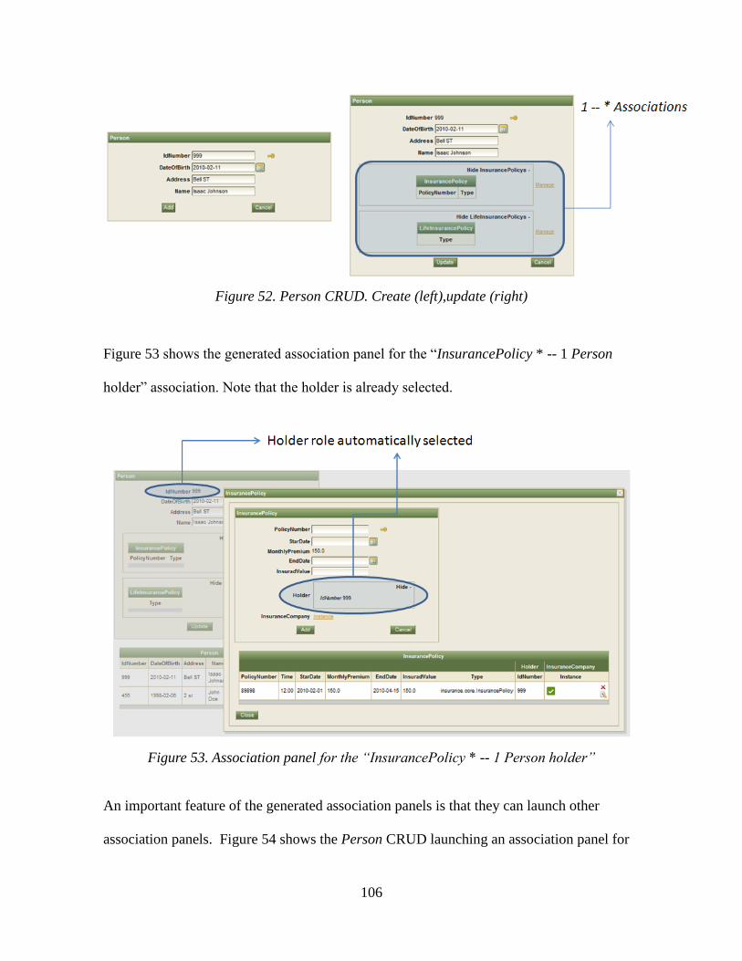
106
Figure 52. Person CRUD. Create (left),update (right)
Figure 53 shows the generated association panel for the ―InsurancePolicy * -- 1 Person
holder‖ association. Note that the holder is already selected.
Figure 53. Association panel for the “InsurancePolicy * -- 1 Person holder”
An important feature of the generated association panels is that they can launch other
association panels. Figure 54 shows the Person CRUD launching an association panel for

107
InsurancePolicy and the latter launching a panel for Transaction.
Figure 54. Association panel launching an association panel
5.2.2.6 Grids
Grids are the components used to show the available instances in a tabular form. For a
specific class, the generated grid contains one column for each defined attribute and one
column for each key attribute of each 1 – X association. A type column is always included.
This column was added to point out when a row is an instance of the class maintained by
the current CRUD, or when it is an instance of a child class of the class being maintained.
The first column from the right contains icons to fire actions like edit, delete or select;
however, a CRUD can only delete instances of its own type. Figure 55 shows the generated
grid for the InsuredProperty class.

108
Figure 55. InsuredProperty generated grid. Note that the delete action is only available for
the row with InsuredProperty type
If a grid has more than 10 rows, a pager is automatically added. Figure 56 shows the pager
component.
Figure 56. Pager component
5.2.2.7 Validations
While Umple generates validation code to maintain the defined associations, UIGU adds
validation code to enforce correct data conversion from the user‘s input. Both kinds of
validation messages are shown above the main form. Figure 57 shows a validation message
for the Renewal class

109
Figure 57. Generated validation message.
5.2.2.8 Singletons
Given that a singleton class has only one instance, there is no a singleton CRUD strictly
speaking. To manage singletons and their relationships, UIGU generates a web form with
the required links. By definition, a singleton cannot be the many side of an association and
cannot have not initialized attributes (its constructor does not have arguments). Since there
is only one instance, the generated view does not contain a grid.
Figure 58 shows the singleton view generated for the InsuranceCompany class in the
Insurance System example.

110
Figure 58 . Singleton. InsuranceCompany view
If a class has an association to a singleton class, and this association is mandatory, the
singleton instance is automatically selected. Otherwise, if the association is optional, an
instance link is rendered to associate the singleton class, and a delete icon is showed to
break the association. Figure 59 shows the components rendered to associate singletons.
Figure 59. Form components to associate singletons. Mandatory (left), optional not
selected (middle), optional selected (right)
To show associations to singletons in a grid, an instance column is added. A checkmark
icon is rendered if the instance is associated, and a ―N/A‖ label is rendered otherwise.
Figure 60 shows the column added to the grids when a class is associated to a singleton.
Figure 60. Column representation of an association to a singleton.
Associated (left), not associated (right)
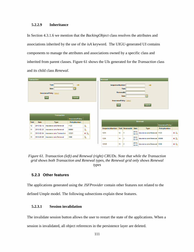
111
5.2.2.9 Inheritance
In Section 4.3.1.6 we mention that the BackingObject class resolves the attributes and
associations inherited by the use of the isA keyword. The UIGU-generated UI contains
components to manage the attributes and associations owned by a specific class and
inherited from parent classes. Figure 61 shows the UIs generated for the Transaction class
and its child class Renewal.
Figure 61. Transaction (left) and Renewal (right) CRUDs. Note that while the Transaction
grid shows both Transaction and Renewal types, the Renewal grid only shows Renewal
types
5.2.3 Other features
The applications generated using the JSFProvider contain other features not related to the
defined Umple model. The following subsections explain these features.
5.2.3.1 Session invalidation
The invalidate session button allows the user to restart the state of the applications. When a
session is invalidated, all object references in the persistence layer are deleted.
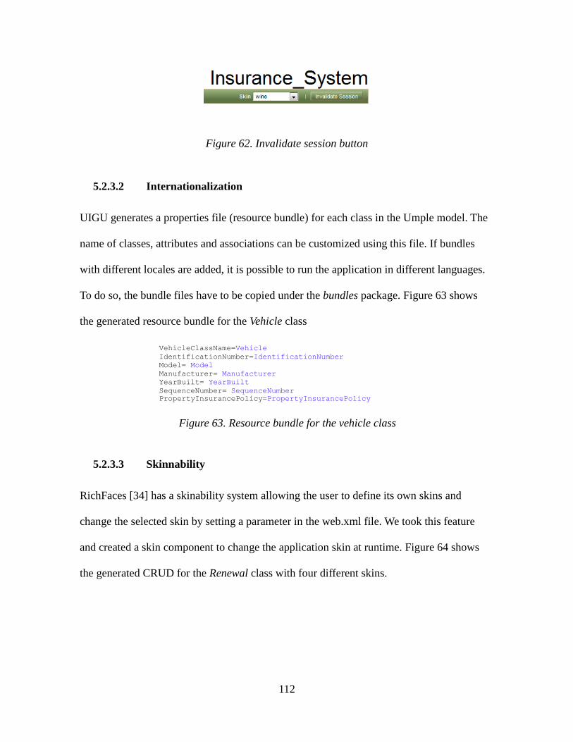
112
Figure 62. Invalidate session button
5.2.3.2 Internationalization
UIGU generates a properties file (resource bundle) for each class in the Umple model. The
name of classes, attributes and associations can be customized using this file. If bundles
with different locales are added, it is possible to run the application in different languages.
To do so, the bundle files have to be copied under the bundles package. Figure 63 shows
the generated resource bundle for the Vehicle class
5.2.3.3 Skinnability
RichFaces [34] has a skinability system allowing the user to define its own skins and
change the selected skin by setting a parameter in the web.xml file. We took this feature
and created a skin component to change the application skin at runtime. Figure 64 shows
the generated CRUD for the Renewal class with four different skins.
VehicleClassName=Vehicle
IdentificationNumber=IdentificationNumber
Model= Model
Manufacturer= Manufacturer
YearBuilt= YearBuilt
SequenceNumber= SequenceNumber
PropertyInsurancePolicy=PropertyInsurancePolicy
Figure 63. Resource bundle for the vehicle class

113
Figure 64. Different skins for the Renewal CRUD. 1) Wine, 2) Classic, 3) JapanCherry, 4)
Ruby. Note the skin combo in the upper-right corner.
In summary, in order to install and run the JSFProvider, besides the Java Runtime
Environment (version 5 or higher), the user has to install and configure an application
server (e.g. JBoss) or a servlet container (e.g. Tomcat). For compilation, Apache Ant is
highly recommended (but not mandatory).
The JSFProvider creates a complete web application that can be reused and converted into

114
a real application. However, if UIGU is used only for rapid prototyping purposes, the
overhead of installing and configuring the server, compiling the application and deploying
the war file using ant can be excessive. If the user‘s intention is just validate the model,
then a more agile UIProvider is desired. Next chapter will introduce a simpler provider
which generates ready-to-run applications.

115
6 Extending UIGU
As we mentioned in Section 4.3 the architecture of UIGU is divided into 3 levels:
GUIModel, GUIGenerator and UIProviders. This approach was taken to allow UIGU to
generate UI code for different technologies that reuse components in other layers.
The JSFProvider creates complete web applications to be deployed in an application server.
The advantages of these generated applications are:
The applications can be accessed using a web browser without installing or
deploying any software in the client.
The adoption of the DAO+Factory and the MVC patterns reduces the impact of
converting the generated application into a real JSF web application.
However, if the application being designed is not going to be a web application or the target
technology is not JSF or any other Java technology, these advantages are not important for
the system modeler. If UIGU is used as a tool to generate default prototypes for an Umple
model, a more agile provider is suitable; this provider should avoid deployment steps. To
accomplish this, a different technology had to be selected to create ready-to-run
applications. In Section 2.7.2 we mentioned that the JavaFX technology can create both
web and desktop applications; to execute these applications, the only requirement is that the
user must install the Java Runtime Environment (JRE) version 6.

116
In this chapter we will discuss how to create ready-to-run applications by developing a
simple JavaFX UIProvider. The simple School --Person model example defined in Section
4.3 will be used to compare the generated outputs of each UIProvider. Figure 65 shows its
Umple model.
Figure 65. School -- Person model
6.1 UIProvider classes
As with the JSFProvider, the JFXProvider must extend the UIFactory, AbstractProvider
and AbstractUIGenerator classes to interact with the GUIGenerator and GUIModel
components. These components generate the DAO layer, read the fragments, parse the
fragments, parse the resource bundles and create the BackingObject instances with the
attribute classification, keys, association classification, inherited fields and inherited
associations for each class defined in the Umple model. The source code of the required
classes can be found in http://www.site.uottawa.ca/~tcl/gradtheses/jsolano/src/JFXProvider

117
6.2 Fragments
UIGU allows the declaration controller and view fragments to manage the different types of
attributes and associations. Given that JavaFX is not a pure MVC framework, both view
and controller components are coded in a single file called FX script. However, the code
required to manage a single attribute can be classified into controller fragments and (GUI)
flow fragments. The former have the same responsibilities as the controller fragments in the
JSFProvider plus the initialization of the UIComponets (e.g. a TextBox); the latter
fragments have to modify the behavior of a UIComponent for a specific CRUD step. Table
23 shows the (controller) definition fragment for a settable String attribute, the Umple
definition of the School‘s name attribute, its generated code and the generated UI.
Fragment var <%=attVar.getName()%>#4# = TextBox {
columns: 15
editable: #1#
text: #2#
visible: #5#
};
var <%=attVar.getName()%>#4#Box= HBox {
spacing: 15;
content: [ <%=attVar.getName()%>#4#, getImg(#3#) ]}
Umple
definition
String name;
key{name}
Generated
code
var nameField = TextBox {
columns: 15
editable: true
text: ""
visible: true
};
var nameFieldBox= HBox {
spacing: 15;
content: [ nameField, getImg(true) ]}
Generated UI
Table 23. Settable String controller fragment and the generated output for the School's
name attribute

118
In this example, the name field is part of the key definition of the School class. Given that
key attributes cannot be edited, the (view) create fragment must enable the attribute
Textbox, while the (view) edit fragment has to generate the required code to deactivate
editing in the Textbox. Table 24 shows the create and edit fragments, and the generated
code for the School‘s name attribute.
CRUD step Fragment Generate code
Create <% AttributeVariable attVar =
(AttributeVariable) argument; %>
<% if (attVar.getValue()==null){ %>
<%=attVar.getName()%>Field.editable=true;
<% } else {%>
<%=attVar.getName()%>Field.editable=false;
<%}%>
nameField.editable=true;
Edit <%=attVar.getName()%>Field.editable=false; nameField.editable=false;
Table 24. View fragments for the School's name attribute. Note that the create fragment also
handles default values
6.3 Main Templates
As in the case of the JSFProvider, the JFXProvider requires main templates to join all
fragments in a compilation unit. Table 25 summarizes these main templates.

119
Template Purpose ParameterType
View This template contains the form with the
fields and association links to create new
objects for a single class. It includes an
instance of the grid generated by the Table
template.
Output: <ClassType>View.fx
NORMAL_CLASS_BY_CLASS
Table A Java class that creates a jTable to
showing the objects created in the system
for a given type. It provides the buttons to
select (for update) and delete the object.
Output: <ClassType> Table.java
NORMAL_CLASS_BY_CLASS
KeyTable A Java class that creates a jTable to show
the keys of the selected objects in a many
(*) association.
Output: <ClassType>KeyTable.java
NORMAL_CLASS_BY_CLASS
Menu This template creates a JMenu with the
links to access CRUD. Output: Menu.fx
ALL_CLASSES
Application This generates a Utility class used to
handle the main window. This class
controls the window events and the
scrolling.
Output: Application.fx
NONE
PopUp Similar to main but, for popup windows. None
Main Generates the entry point for all CRUDs.
This template uses Application and Menu.
Output: MainView.fx
NONE
SelectOneView A class that creates an jTable with a button
to select an object (for associations). It has
a panel to show the current selection. It
uses the related KeyTable to show the
selected elements.
Output: <ClassType> SelectOneView.fx
NORMAL_CLASS_BY_CLASS
SelectManyView A grid with a button to select multiple
objects (for associations). It has a panel to
show the current selection in a KeyTable.
Output: <ClassType> SelectManyView.fx.
NORMAL_CLASS_BY_CLASS
Table 25. JFXProvider main templates

120
6.4 Navigation model
Unlike JSF applications, JavaFX objects do not require a scope definition. Therefore,
JavaFX applications do not require special contexts to store objects and values between two
different requests, and configuration files to set it up. This simplifies the navigation model
depicted in Section 4.3.3.6. Another important consequence is that the required main
templates are fewer than in the JSF counterpart. The generated views resemble those
generated by the JSFProvider. Figures 65 to 68 compare the generated views for the
School – Person Model.
Figure 66. School CRUD. JavaFX (left), JSF (right)

121
Figure 67. Person CRUD. JavaFX (left), JSF (right)
Figure 68. Linking a student (Person) to an School. JavaFX (left), JSF (right)
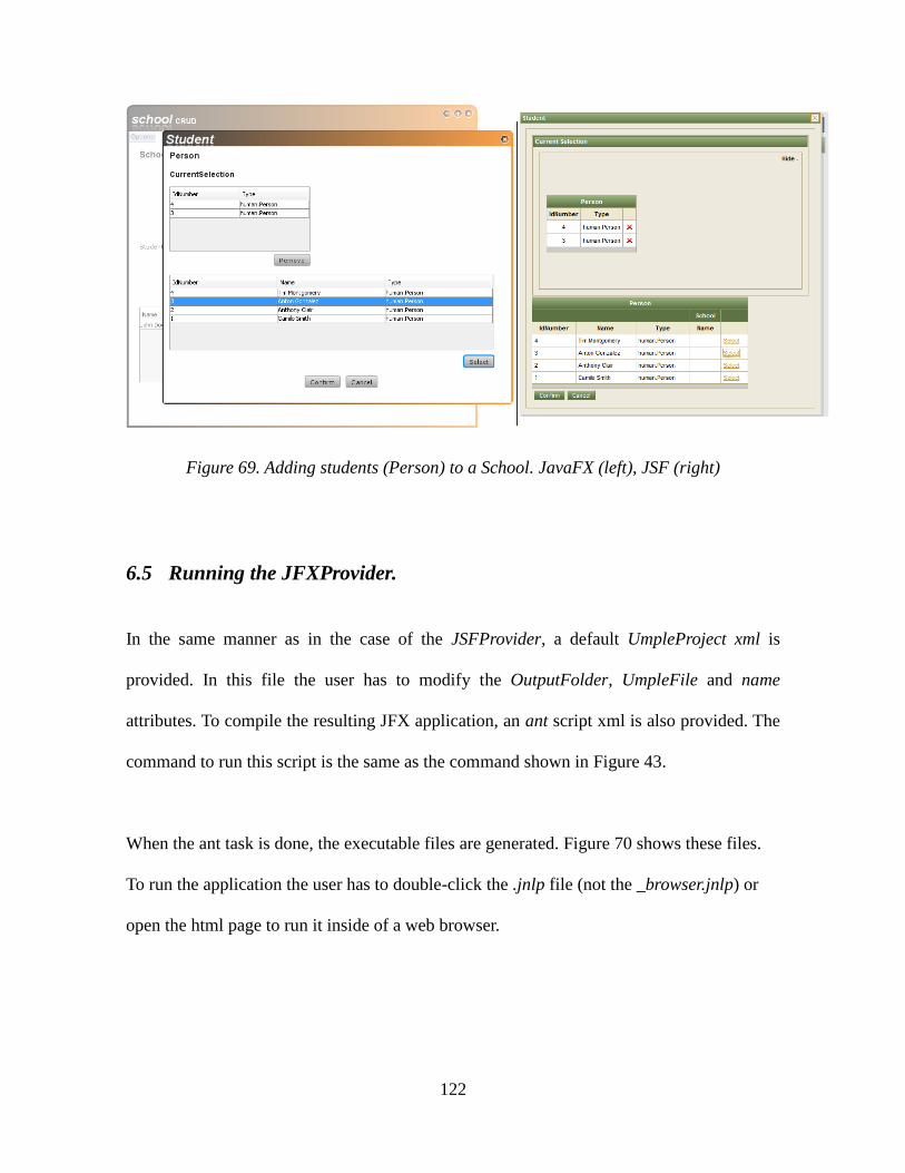
122
Figure 69. Adding students (Person) to a School. JavaFX (left), JSF (right)
6.5 Running the JFXProvider.
In the same manner as in the case of the JSFProvider, a default UmpleProject xml is
provided. In this file the user has to modify the OutputFolder, UmpleFile and name
attributes. To compile the resulting JFX application, an ant script xml is also provided. The
command to run this script is the same as the command shown in Figure 43.
When the ant task is done, the executable files are generated. Figure 70 shows these files.
To run the application the user has to double-click the .jnlp file (not the _browser.jnlp) or
open the html page to run it inside of a web browser.

123
.
Figure 70. JFXProvider executable files
6.6 Current state
The JFXProvider currently does not support all the Umple subset supported by the
JSFProvider. Support for singletons, Date and Time attributes, defaulted and internal
modifiers, and 1--* associations (currently it supports only 0--* , 1 -- 0..1 and *--*) are
planned for future releases.

124
7 Conclusions
The ideas and concepts presented in this thesis are part of an ongoing effort to unify
modeling and implementation of a system. Umple filled the gap between modeling and the
implementation of the domain objects and UIGU was developed to take these objects to the
UI level. Even in this initial version is easy to see how UIGU can help software modelers
to understand the implications of their modeling decisions and also how UIGU- and
Umple- generated objects can reduce the development time of a software solution.
7.1 Research Questions
We have proposed five questions in Chapter 3. These were the research questions our thesis
hoped to answer, or provide solutions to. This section briefly outlines our answers to these
research questions.
RQ1: How can we bridge the gap between models and the UI?
It is necessary to use code generation techniques to fill that gap. However, a new question
arises: which is the best generation approach to fill it? There are different answers to this
question. These answers depend on the selected generation approach. Strictly speaking,
this research did not start completely from scratch. Since the Umple language was in an
operative state, and it provided a complete metamodel to get the required details about the
model (attributes, associations, attribute modifiers, etc.). We analyzed the different code

125
generation approaches and decided that taking advantage of the Umple compiler and the
generated abstract semantic graph, where each node is an instances of the metamodel, was
the best approach. Having this, the multi-tier generator model was the most suitable
approach to implement UIGU, for the following reasons:
Umple uses templates to generate the domain objects and this model supports the
use of templates to produce the output. In this way the skills required to understand
and expand Umple are close to those required to do the same with UIGU.
The textual model is the single input file required. To get rid of reading and parsing
tasks, we integrated the Umple generation process to UIGU‘s generation process.
Since a controller and view layers (or tiers) had to be generated on top of the
domain objects partial code generators were not appropriate.
RQ2: What are the advantages and disadvantages of generating UI code starting with the
abstract semantic graph generated by the Umple compiler?
As an Umple tool, UIGU should follow the Umple solution. In this way many Umple
concepts were ported to UIGU (i.e. attribute modifiers, namespaces, multiplicity handling,
etc.). Integrating the Umple compiler into the UIGU generation process not only freed us
from parsing and reading the model file, but also gave us access to the abstract syntax
graph to navigate through the model that is the subject of generation. This graph contains
information about the model that could not be obtained through introspection or reflection
techniques without additional specifications from the user.
The main disadvantage is that since UIGU was built on top of Umple, it shares the same

126
limitations as Umple plus its own specific limitations. For instance, an Umple limitation is
that it currently does not fully support 1 – 1 associations and therefore UIGU does not
either. This is only a minor limitation though, since pragmatically, 1 -- 1 associations tend
to be poor modeling choices, with the preferred modeling solution normally being to merge
the two classes. UIGU-specific limitations are related to Umple constructs that UIGU does
not support yet (i.e. autoUnique, codeInjection, extraCode, etc.)
RQ3: What are the limits of automatic UI generation from the model?
All modeling techniques contain limited information about the system. Therefore the limits
of the code generated from these models is directly linked to the amount of information
provided by these models (i.e. in a reflexive association there is no standard notation in
Umple to create a constraint stating that an instance cannot be associated with itself).
Several efforts have been made to expand the scope of software models, One of them, OCL
(Object Constraint Language [38]), was added to UML to provide constraints and query
expressions that could not be expressed by diagrammatic notation. Adding OCL-like
constraints to Umple and (reading them with UIGU) will help to create UI applications that
can represent the user‘s requirements in closer manner.
RQ4: To what extent can generated default UI code be customized and extended?
Generated UI code has to follow appropriate design patterns to maintain the responsibilities
and roles of each piece of code appropriately separated. UIGU applications use the DAO
and Factory patterns to keep the persistence layer separated from upper layers (controller

127
and view). In this way, the user can provide his own set of DAO classes to switch the
persistence media from the default (fake) persistence to a real persistence technology. The
adoption of the MVC in the JSFProvider resulted in the generation of objects with a
defined set of responsibilities. These objects can be customized (or even replaced) by the
user with no impact in other objects and layers, if the public interface of an object is
respected. Other features like resource bundles and css skins will also help the user to
convert the generated application into a real and fully functional application.
RQ5: How can a GUI generator generate UI code for different UI technologies?
Similar UI technologies (i.e Struts and JSF) can be totally different from an implementation
point of view, even if they are created for the same programming language. Differences in
the underlying technology (e.g. web html pages vs swing windows), configuration files,
custom classes, custom tags, etc. Turn the creation of a multi-target generator into a
complex task. However, in our research we found that CRUD applications have a well-
defined set of operations and steps that can be implemented by relatively small pieces of
code and defined these as fragments.
The UIGU approach gathers all common tasks (fragment declarations, utility classes,
association classification, inheritance detection, reading files, writing files, etc.) in the
GUIModel and GUIGenerator components, and introduces the concepts of fragments and
main templates to delegate specific UI constructions to the UI providers. Using this
technique, the developer of a specific UIProvider can be focused on rendering tasks.
However the differences between UI technologies can result into a potentially high number

128
of fragments and templates.
7.2 Contributions
The following are the main contributions of this research.
UIGU provides a clean and fast way of see the impact of a design decision in a default (but
fully functional) UI application. This will help software modelers to catch potential
mistakes like redundant associations, required associations, special attributes (defaulted,
immutable, etc.), incorrect attributes types, wrong multiplicities, etc. UIGU will also help to
add improvements like class realization (inheritance), key definitions, singleton definition,
among others.
The UI generation architecture and its distribution of the responsibilities among the three
main components of UIGU (Model, Generator and provider), is an effective way to
implement multi-component-framework user interface generators
This research contributed to development of the Umple language in the following ways:
The key keyword was added to the language to generate effective equality tests.
The initialization of the Time and Date attributes was upgraded to allow
initialization from literals (strings).
Code structures like doAfter, and doBefore were added to Umple after analyzing the
different fragments provided by a fragment resolver
Many bugs where discovered and addressed.

129
7.3 Future work and possibilities
This thesis is the one of several different research subprojects related to Umple. There is
much work and possible research to be done in order to improve UIGU and its
functionality.
7.3.1 Expanding UIGU
This initial version of UIGU is intended to be a prototype providing a proof of concept.
Consequently we had to limit the scope of our work.
UIGU does not cover all Umple language features. The initial subset of Umple features
supported by UIGU was selected to allow the creation of effective CRUD applications,
however there are other data types to be supported (e.g. list, enum, etc), keywords (unique,
autoUnique, etc.) . These features can be supported easily by the definition of new
fragments. Other Umple constructs (e.g. Interfaces) should imply the development of new
classes and main templates. New UIProviders to support other technologies can also be
developed.
Umple research is growing in multiple directions. Support for state machines is currently
being added to the Umple language; OCL support and concurrent modeling support are also
being considered. Given that these research lines can also be taken to the UI level, UIGU
has to be expanded in order to remain as a valid UI generator for the Umple language.

130
7.4 Validating UIGU
UIGU was tested using the examples listed in Appendix III. However, to gather feedback,
UIGU should be tested in more complex models and by experienced software modelers.
Initially UIGU could be used as a teaching tool. This will help not only to test its concept,
but also to show students how UML concepts can be mapped to textual models and these
models can be taken to the UI level. Besides these advantages UIGU provides to students,
student exposure to UIGU would make it more possible that it will gain more research
interest and developer support in the future. Once stabilized and tested, UIGU could be
opened to the open source community to allow them to use it and contribute.

131
References
[1] P. Pinheiro da Silva and N.W. Paton, User Interface Modeling in UMLi. IEEE
software, pp. 62-69, 2003
[2] K. Stirewalt, S. Rugaber, Automating UI Generation by Model Composition. 13th
IEEE International Conference on Automated Software Engineering (ASE'98),
pp.177, 1998
[3] M. Flower, History of the evolution of MVC and derivatives. 2006
http://www.martinfowler.com/eaaDev/uiArchs.html
[4] D. Brestovansky, Exploring Textual Modeling using the Umple Language.
University of Ottawa, 2008.
http://www.site.uottawa.ca/~tcl/gradtheses/dbrestovansky/
[5] T. Howard, The Smalltalk Developers Guide To Visual Works. Cambridge University
Press, pp. 379-381, 1995
[6] H. Kilov, From semantic to object-oriented data modeling. Proceedings of the First
International Conference on Systems Integration, pp. 385-393, April 1990
[7] L, Cardelli, Typeful Programming. Digital Equipment Corporation, Systems
Research Center, pp 8-15, 1993
http://lucacardelli.name/Papers/TypefulProg.A4.pdf
[8] A.Forward, O. Badreddin, T. Lethbridge, Exploring a Model-Oriented and
Executable Syntax for UML Attributes in the Umple Language v2. University of
Ottawa, 2009
[9] A.Forward, T. Lethbridge, Improving Program Comprehension by Enhancing
Program Constructs: Ananalysis of the Umple language. University of Ottawa,
2009
[10] J. Herrignton, Code Generation in Action. Manning Publications Co, ch. 2, 2003
[11] JSP 2.0 - Java Server Pages documentation,
http://java.sun.com/products/jsp/docs.html

132
[12] K. Fertalj, M. Brcic, A Source Code Generator Based on UML Specification.
International Journal Of Computers And Communications, Issue 1 vol 2, pp. 10-19,
2008
[13] A. Elbibas, M. J. Ridley, Developing Web entry forms Based on METADATA.
ICWE 04-International Conference on Web Engineering, Munich (Germany). 2004.
[14] M. A. Mgheder, M. J. Ridley, Automatic Generation of Web User Interfaces in PHP
Using Database Metadata. 3th IEEE International Conference on Internet and Web
Applications and Services, pp. 426-430, 2008
[15] A., Scott, Mapping objects to relational databases. Roning International, 2000 http://www.AmbySoft.com/mappingObjects.pdf
[16] M. A. Mgheder, M. J. Ridley, Using Database Metadata and its Semantics to
Generate Automatic and Dynamic Web Entry Forms. Proceedings of the World
Congress on Engineering and Computer Science 2007 WCECS 2007, pp. 654-658,
October 2007
[17] M. Polo, M. Piattini, F. Ruiz, Reflective Persistence (Reflective CRUD). Escuela
Superior de Informática University of Castilla-La Mancha, 2001
[18] M. J. Rettig, M. Fowler, Reflection vs. code generation, 2001
http://www.javaworld.com/javaworld/jw-11-2001/jw-1102-codegen.html
[19] W3C XPATH language specification, 2007
http://www.w3.org/TR/xpath20/
[20] S. Sarkar, C. Cleveland, Code Generation Using Xml Based Document
Transformation. theserverside.com , 2007
http://www.theserverside.com/tt/articles/content/XMLCodeGen/xmltransform.pdf
[21] S. Sarkar, Model driven programming using XSLT. XML-JOURNAL, pp. 42-51
August 2002
[22] P. Lay, S. Transforming XML Schemas into Java Swing GUIs. L¨uttringhaus-
Kappel. Institut f¨ur Informatik III, Universit¨at Bonn volume 50 of LNI
proceedings pp. 271-276, 2004

133
[23] R. Popma, Introduction to JET. Azurri Ltda, Eclipse corner articles, 2007
http://www.eclipse.org/articles/Article-JET/jet_tutorial1.html
[24] ERb - Ruby, http://www.ruby-doc.org/stdlib/libdoc/erb/rdoc/classes/ERB.html
[25] HTML::Mason, http://www.masonhq.com.
[26] S. Huang, H Zhang, Research on Improved MVC Design pattern Based on Struts
and XSL. International Symposium on Information Science and Engineering, 2008
[27] V. Chopra, Beginning JavaServer Pages. Wrox Press, ch. 17, 2005
[28] Core J2EE Patterns - Data Access Object. Sun Microsystems
http://java.sun.com/blueprints/corej2eepatterns/Patterns/DataAccessObject.html
[29] D. Matid, D. Butorac, H. Kegalj, Data Access Architecture in Object Oriented
Applications Using Design Patterns. IEEE MELECON, pp. 595-598, 2004
[30] C. Schalk, E. Burns, J. Holmes, JavaServer Faces: “The Complete Reference”.
McGraw-Hill/Osborne. 2007
[31] The Java EE 5Tutorial. Sun Microsystems. ch 10, 2007
http://java.sun.com/javaee/5/docs/tutorial/doc/JavaEETutorial.pdf
[32] Hibernate, Relational Persistence with Java and .Net,
https://www.hibernate.org/328.html
[33] Java Architecture for XML binding -JAXB-, https://jaxb.dev.java.net/
[34] JBoss RichFaces, http://www.jboss.org/richfaces
[35] Facelets, https://facelets.dev.java.net/
[36] JAR hell, http://incubator.apache.org/depot/version/jar-hell.html
[37] Apache ant, http://ant.apache.org/
[38] OMG OCL 2.2 Specification, 2010
http://www.omg.org/technology/documents/modeling_spec_catalog.htm#OCL

134
APPENDIX I
UMPLE GRAMMAR V. 1.6.3
program- : ( [[comment]] | [[directive]] )*
directive- : [[glossary]] | [[generate]] | [[useStatement]] |
[[namespace]] | [[entity]]
glossary : glossary { [[word]]* }
word : [singular] : [plural] ;
generate- : generate [=generate:Java|Php|Json|Yuml] ;
useStatement- : use [use] ;
namespace- : namespace [namespace] ;
entity- : [[classDefinition]] | [[interfaceDefinition]] |
[[externalDefinition]] | [[associationDefinition]] |
[[associationClassDefinition]]
classDefinition : class [name] { [[classContent]]* }
externalDefinition : external [name] { [[classContent]]* }
interfaceDefinition : interface [name] { [[depend]]* [[extraCode]]? }
associationDefinition : association [name]? { [[association]]* }
associationClassDefinition : associationClass [name] {
[[associationClassContent]]* }
separateMultiplicity : [[multiplicity]] [type,name] ;
association : [[aMultiplicity]] [=arrow:--|->|<-|><] [[aMultiplicity]] ;
aMultiplicity : [[multiplicity]] [type,name]
classContent- : [[comment]] | [[classDefinition]] | [[position]] |
[[isA]] | [[singleton]] | [[depend]] | [[codeInjection]] |
[[keyDefinition]] | [[symmetricReflexiveAssociation]] | [[stateMachine]]
| [[attribute]] | [[myAssociation]] | [[extraCode]]
associationClassContent- : [[comment]] | [[classDefinition]] | [[isA]] |
[[depend]] | [[codeInjection]] | [[keyDefinition]] |
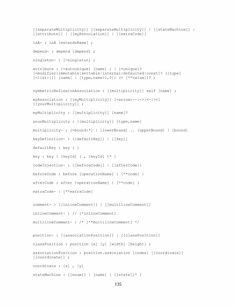
135
[[separateMultiplicity]] [[separateMultiplicity]] | [[stateMachine]] |
[[attribute]] | [[myAssociation]] | [[extraCode]]
isA- : isA [extendsName] ;
depend- : depend [depend] ;
singleton- : [=singleton] ;
attribute : [=autounique] [name] ; | [=unique]?
[=modifier:immutable|settable|internal|defaulted|const]? ([type]
[=list:[]] [name] | [type,name>1,0]) (= [**value])? ;
symmetricReflexiveAssociation : [[multiplicity]] self [name] ;
myAssociation : [[myMultiplicity]] [=arrow:--|->|<-|><]
[[yourMultiplicity]] ;
myMultiplicity : [[multiplicity]] [name]?
yourMultiplicity : [[multiplicity]] [type,name]
multiplicity- : [=bound:*] | [lowerBound] .. [upperBound] | [bound]
keyDefinition- : [[defaultKey]] | [[key]]
defaultKey : key { }
key : key { [keyId] ( , [keyId] )* }
codeInjection- : [[beforeCode]] | [[afterCode]]
beforeCode : before [operationName] { [**code] }
afterCode : after [operationName] { [**code] }
extraCode- : [**extraCode]
comment- : [[inlineComment]] | [[multilineComment]]
inlineComment- : // [*inlineComment]
multilineComment- : /* [**multilineComment] */
position- : [[associationPosition]] | [[classPosition]]
classPosition : position [x] [y] [width] [height] ;
associationPosition : position.association [index] [[coordinate]]
[[coordinate]] ;
coordinate : [x] , [y]
stateMachine : [[enum]] | [name] { [[state]]* }

136
enum- : [name] { } | [name] { [stateName] (, [stateName])* }
state : [stateName] { [[stateEntity]]* }
stateEntity- : [[transition]] | [[entryOrExitAction]] | [[nestedState]] |
[[activity]]
transition : [[guard]] [event] -> [[action]]? [stateName] ; | [event]
[[guard]]? -> [[action]]? [stateName] ; | [[activity]] -> [stateName]
nestedState : [stateName] { [[stateEntity]]* }
action : / { [**actionCode] }
entryOrExitAction : [=type:entry|exit] / { [**actionCode] }
activity : do { [**activityCode] }
guard : [ [**guardCode] ]

137
APPENDIX II
UmpleProject.xsd
<?xml version="1.0" encoding="UTF-8"?>
<xs:schema xmlns:xs="http://www.w3.org/2001/XMLSchema" xmlns:jxb="http://java.sun.com/xml/ns/jaxb" jxb:version="1.0"> <xs:annotation>
<xs:appinfo>
<jxb:globalBindings collectionType="java.util.ArrayList"/> </xs:appinfo>
</xs:annotation>
<xs:element name="UmpleProject"> <xs:complexType>
<xs:sequence>
<xs:element ref="Properties"/> <xs:element ref="GenerationUnits"/>
<xs:element ref="Files"/>
</xs:sequence> <xs:attribute name="name" type="xs:string" use="required"/>
<xs:attribute name="UIFactory" type="xs:string" use="required"/>
<xs:attribute name="OutputFolder" type="xs:string" use="required"/> <xs:attribute name="UmpleFile" type="xs:string" use="required"/>
</xs:complexType>
</xs:element> <xs:element name="Property">
<xs:complexType>
<xs:attribute name="name" type="xs:string" use="required"/> <xs:attribute name="value" type="xs:string" use="required"/>
</xs:complexType> </xs:element>
<xs:element name="Properties">
<xs:complexType> <xs:sequence>
<xs:element ref="Property" minOccurs="0" maxOccurs="unbounded"/>
</xs:sequence> </xs:complexType>
</xs:element>
<xs:element name="GenerationUnits"> <xs:complexType>
<xs:sequence>
<xs:element ref="GenerationUnit" minOccurs="0" maxOccurs="unbounded"/> </xs:sequence>
</xs:complexType>
</xs:element> <xs:element name="GenerationUnit">
<xs:complexType>
<xs:attribute name="TemplateClass" type="xs:string" use="required"/> <xs:attribute name="TemplatePackage" type="xs:string" use="required"/>
<xs:attribute name="ParameterType" type="xs:string" use="required"/>
<xs:attribute name="PackagePreffix" type="xs:string" use="optional"/> <xs:attribute name="ClassSuffix" type="xs:string" use="optional"/>
<xs:attribute name="OutputName" type="xs:string" use="optional"/>
<xs:attribute name="OutputExtension" type="xs:string" use="optional"/> <xs:attribute name="OutputSubFolder" type="xs:string" use="optional"/>
<xs:attribute name="AddClassNameToRoute" type="xs:string" use="optional" default="NO"/>
</xs:complexType> </xs:element>
<xs:element name="File">
<xs:complexType> <xs:attribute name="InputFolder" type="xs:string" use="required"/>
<xs:attribute name="OutputSubFolder" type="xs:string" use="required"/>
<xs:attribute name="Name" type="xs:string" use="optional"/>
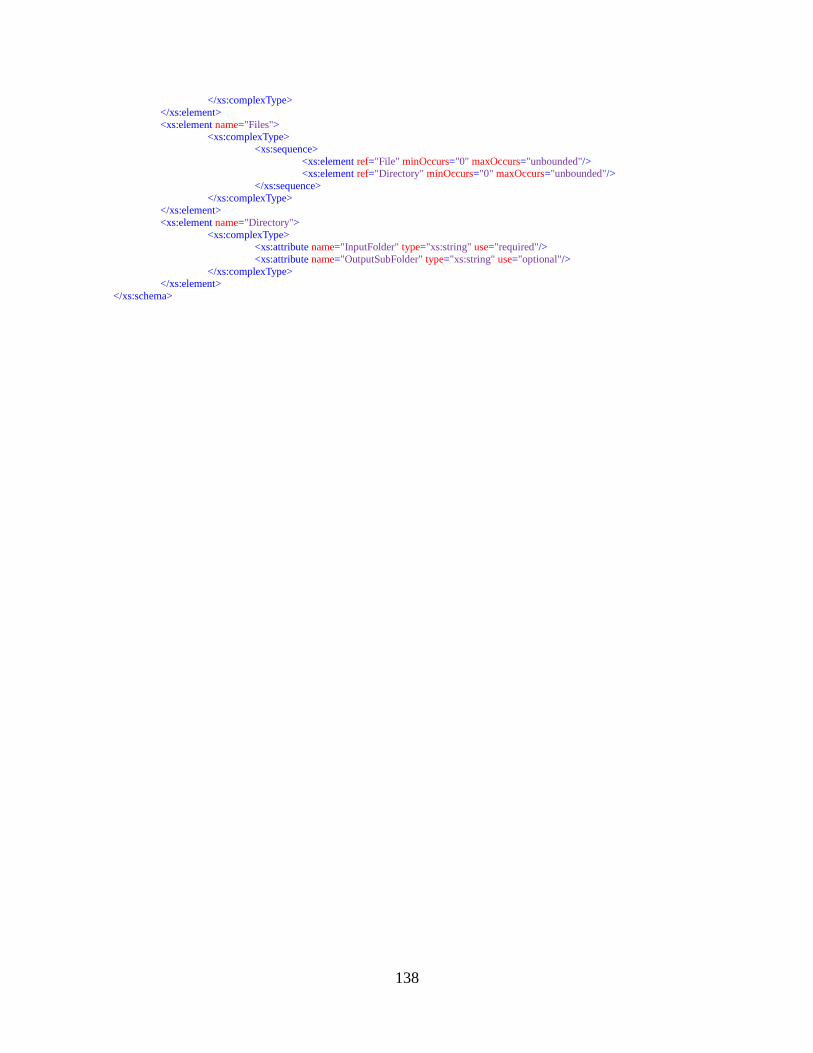
138
</xs:complexType>
</xs:element>
<xs:element name="Files"> <xs:complexType>
<xs:sequence>
<xs:element ref="File" minOccurs="0" maxOccurs="unbounded"/> <xs:element ref="Directory" minOccurs="0" maxOccurs="unbounded"/>
</xs:sequence>
</xs:complexType> </xs:element>
<xs:element name="Directory">
<xs:complexType> <xs:attribute name="InputFolder" type="xs:string" use="required"/>
<xs:attribute name="OutputSubFolder" type="xs:string" use="optional"/>
</xs:complexType> </xs:element>
</xs:schema>

139
APPENDIX III
Examples
School – Person Model
namespace education;
class School {
String name;
String address;
String description;
0..1 -- * Person student;
key{name}
}
namespace human;
class Person {
String name;
Integer idNumber;
key{idNumber}
}
Insurance System.
namespace insurance.core;
class InsuranceCompany{
singleton;
0..1 -- * InsurancePolicy;
}
class InsurancePolicy{

140
String policyNumber;
defaulted Double monthlyPremium=150.0;
Date starDate;
Date endDate;
Double insuradValue;
1 -- * Transaction;
* -- 1 Person holder;
key {policyNumber}
}
class Transaction {
Integer txId;
immutable Date date;
key {txId}
}
class Renewal {
Integer sequenceNumber;
Integer renewalId;
isA Transaction;
key{sequenceNumber}
}
class Claim {
Integer sequenceNumber;
String description;
Double amountClaimed;
key{sequenceNumber}
}
class Person{
Integer idNumber;
String name;
String address;
Date dateOfBirth;
key {idNumber}
}
class LifeInsurancePolicy {
Integer lifeInsurancePolicyId;
isA InsurancePolicy;
* -- 1 Person insuredLife;
* -> * Person beneficiary;
key {lifeInsurancePolicyId;}
}
class PropertyInsurancePolicy{

141
Integer propertyInsurancePolicyId;
isA InsurancePolicy;
key {propertyInsurancePolicyId}
}
class InsuredProperty {
Integer sequenceNumber;
Integer yearBuilt;
0..1 -- 1 PropertyInsurancePolicy;
key{sequenceNumber}
}
class Building {
isA InsuredProperty;
String address;
Double floorArea;
key {address}
}
class Vehicle{
isA InsuredProperty;
String identificationNumber;
String manufacturer;
String model;
key{identificationNumber}
}
Airline System
namespace airline;
class Airline{
singleton;
1 -- * RegularFlight;
1 -- * Person;
}
class RegularFlight{
Time time;
Integer flightNumber;
1 -- * SpecificFlight;
key{flightNumber}

142
}
class SpecificFlight{
Integer flightId;
Date date;
key{flightId}
}
class PassengerRole
{
isA PersonRole;
immutable String name ;
1 -- * Booking;
key{name}
}
class EmployeeRole
{
String jobFunction;
isA PersonRole;
* -- 0..1 EmployeeRole supervisor;
* -- * SpecificFlight;
key{jobFunction}
}
class Person
{
String name;
Integer idNumber;
1 -- 0..2 PersonRole;
key{idNumber}
}
class PersonRole{}
class Booking{
Integer sequenceNumber;
String seatNumber;
* Booking -- 1 SpecificFlight;
key{sequenceNumber}
}

143
APPENDIX IV
UmpleProject.xml for the Insurance_System
<?xml version="1.0" encoding="UTF-8"?>
<!-- UMPLE PROJECT JSF PROVIDER--> <UmpleProject UmpleFile="Insurance.ump" name="Insurance_System" UIFactory="cruise.ui.jsf.JSFFactory"
OutputFolder="InsuranceApp" xsi:noNamespaceSchemaLocation="UmpleProject.xsd"
xmlns:xsi="http://www.w3.org/2001/XMLSchema-instance"> <Properties>
<Property name="UMPLE_FOLDER" value="JavaSource" />
<Property name="ATTRIBUTE_CONFIGURATOR" value="xml/AttributeConfigurator.xml" /> <Property name="GUI_ATTRIBUTE_CONFIGURATOR" value="xml/GUIConfigurator.xml" />
<Property name="PROVIDER_JAR" value="JSFProvider.jar" /> <!-- JSF PROVIDER Properties-->
<Property name="BCK_OBJECT_SUFFIX" value="Bean" />
<Property name="PACKAGE_PREFIX" value="web" /> </Properties>
<GenerationUnits>
<GenerationUnit OutputSubFolder="JavaSource" PackagePreffix="dao" OutputExtension="java" TemplatePackage="cruise.data.impl.dao" TemplateClass="DAOInterface" ClassSuffix="DAO"
ParameterType="NORMAL_CLASS_BY_CLASS"/>
<GenerationUnit OutputSubFolder="JavaSource" PackagePreffix="dao.keys" OutputExtension="java"
TemplatePackage="cruise.data.impl.dao.generic" TemplateClass="KeyClass" OutputPackage="dao.keys" ClassSuffix="Key"
ParameterType="NORMAL_CLASS_BY_CLASS"/>
<GenerationUnit OutputSubFolder="JavaSource" PackagePreffix="dao.keys" OutputExtension="java" TemplatePackage="cruise.data.impl.dao.generic.impl" TemplateClass="IKey" OutputName="IKey" ParameterType="NONE"/>
<GenerationUnit OutputSubFolder="JavaSource" PackagePreffix="dao.factory" OutputExtension="java"
TemplatePackage="cruise.data.impl.dao.factory" TemplateClass="DAOFactory" OutputName="DAOFactory" ParameterType="ALL_NORMAL_CLASSES"/>
<GenerationUnit OutputSubFolder="JavaSource" PackagePreffix="dao.factory" OutputExtension="java"
TemplatePackage="cruise.data.impl.dao.factory" TemplateClass="FakeDAOFactory" OutputName="FakeDAOFactory" ParameterType="ALL_NORMAL_CLASSES"/>
<GenerationUnit OutputSubFolder="JavaSource" PackagePreffix="dao.generic" OutputExtension="java"
TemplatePackage="cruise.data.impl.dao.generic" TemplateClass="GenericDAO" OutputName="GenericDAO" ParameterType="NONE"/>
<GenerationUnit OutputSubFolder="JavaSource" PackagePreffix="dao.generic.impl" OutputExtension="java"
TemplatePackage="cruise.data.impl.dao.generic.impl" TemplateClass="GenericFakeDAO" OutputName="GenericFakeDAO" ParameterType="NONE"/>
<GenerationUnit OutputSubFolder="JavaSource" PackagePreffix="dao.session" OutputExtension="java"
TemplatePackage="cruise.data.impl.dao.session" TemplateClass="ObjectRepository" OutputName="ObjectRepository" ParameterType="ALL_NORMAL_CLASSES"/>
<GenerationUnit OutputSubFolder="JavaSource" PackagePreffix="dao.session" OutputExtension="java"
TemplatePackage="cruise.data.impl.dao.session" TemplateClass="Session" OutputName="Session" ParameterType="NONE"/> <GenerationUnit OutputSubFolder="JavaSource" PackagePreffix="bundles" OutputExtension="properties"
TemplatePackage="cruise.data.impl.bundles" TemplateClass="ResourceBundle" OutputPackage="bundles"
ParameterType="NORMAL_CLASS_BY_CLASS"/> <GenerationUnit OutputSubFolder="JavaSource" PackagePreffix="bundles" OutputExtension="properties"
TemplatePackage="cruise.data.impl.bundles" TemplateClass="ResourceBundle" OutputPackage="bundles"
ParameterType="SINGLETON_CLASS_BY_CLASS"/> <!-- JSF PROVIDER GenerationUnits-->
<!-- JSF PROVIDER Beans and Utils-->
<GenerationUnit OutputSubFolder="JavaSource" PackagePreffix="web.components.bean" OutputExtension="java" TemplatePackage="cruise.ui.jsf.templates.impl.components" TemplateClass="SkinBean" OutputName="SkinBean"
ParameterType="NONE"/>
<GenerationUnit OutputSubFolder="JavaSource" PackagePreffix="web.components.bean" OutputExtension="java" TemplatePackage="cruise.ui.jsf.templates.impl.components" TemplateClass="TimeBean" OutputName="TimeBean"
ParameterType="NONE"/>
<GenerationUnit OutputSubFolder="JavaSource" PackagePreffix="web.control" OutputExtension="java" TemplatePackage="cruise.ui.jsf.templates.impl.control" TemplateClass="BeanLinker" OutputName="BeanLinker"
ParameterType="NONE"/>

144
<GenerationUnit OutputSubFolder="JavaSource" PackagePreffix="web.control" OutputExtension="java"
TemplatePackage="cruise.ui.jsf.templates.impl.control" TemplateClass="MainBean" OutputName="MainBean"
ParameterType="NONE"/> <GenerationUnit OutputSubFolder="JavaSource" PackagePreffix="web.utils" OutputExtension="java"
TemplatePackage="cruise.ui.jsf.templates.impl.utils" TemplateClass="PageFlowUtils" OutputName="PageFlowUtils"
ParameterType="NONE"/> <GenerationUnit OutputSubFolder="JavaSource" PackagePreffix="web" OutputExtension="java"
TemplatePackage="cruise.ui.jsf.templates.impl" TemplateClass="BckBean" ClassSuffix="Bean"
ParameterType="NORMAL_CLASS_BY_CLASS"/> <GenerationUnit OutputSubFolder="JavaSource" PackagePreffix="web" OutputExtension="java"
TemplatePackage="cruise.ui.jsf.templates.impl" TemplateClass="BckBeanSingleton" ClassSuffix="Bean"
ParameterType="SINGLETON_CLASS_BY_CLASS"/> <!-- JSF PROVIDER Config Files-->
<GenerationUnit OutputSubFolder="WebContent/WEB-INF" OutputExtension="xml"
TemplatePackage="cruise.ui.jsf.templates.impl.GUI.config" TemplateClass="WebXML" OutputName="web" ParameterType="NONE"/>
<GenerationUnit OutputSubFolder="WebContent/WEB-INF" OutputExtension="xml"
TemplatePackage="cruise.ui.jsf.templates.impl.GUI.config" TemplateClass="FacesConfig" OutputName="faces-config" ParameterType="ALL_CLASSES"/>
<GenerationUnit OutputSubFolder="WebContent/pages" PackagePreffix="templates" OutputExtension="xhtml"
TemplatePackage="cruise.ui.jsf.templates.impl.GUI.templates" TemplateClass="Common" OutputName="common" ParameterType="ALL_CLASSES"/>
<!-- JSF PROVIDER web pages Files-->
<GenerationUnit OutputSubFolder="WebContent/pages" OutputExtension="xhtml" TemplatePackage="cruise.ui.jsf.templates.impl.GUI" TemplateClass="Home" OutputName="home" ParameterType="NONE"/>
<GenerationUnit OutputSubFolder="WebContent/pages" OutputExtension="xhtml" TemplatePackage="cruise.ui.jsf.templates.impl.GUI" TemplateClass="BaseInsertable" ClassSuffix="Insertable"
AddClassNameToRoute="YES" ParameterType="NORMAL_CLASS_BY_CLASS"/>
<GenerationUnit OutputSubFolder="WebContent/pages" OutputExtension="xhtml" TemplatePackage="cruise.ui.jsf.templates.impl.GUI" TemplateClass="BaseMain" ClassSuffix="Main" AddClassNameToRoute="YES"
ParameterType="NORMAL_CLASS_BY_CLASS"/>
<GenerationUnit OutputSubFolder="WebContent/pages" OutputExtension="xhtml" TemplatePackage="cruise.ui.jsf.templates.impl.GUI" TemplateClass="Grid" OutputName="grid" AddClassNameToRoute="YES"
ParameterType="NORMAL_CLASS_BY_CLASS"/>
<GenerationUnit OutputSubFolder="WebContent/pages" OutputExtension="xhtml" TemplatePackage="cruise.ui.jsf.templates.impl.GUI" TemplateClass="GridSelectMany" OutputName="gridSelectMany"
AddClassNameToRoute="YES" ParameterType="NORMAL_CLASS_BY_CLASS"/>
<GenerationUnit OutputSubFolder="WebContent/pages" OutputExtension="xhtml" TemplatePackage="cruise.ui.jsf.templates.impl.GUI" TemplateClass="GridSelectOne" OutputName="gridSelectOne"
AddClassNameToRoute="YES" ParameterType="NORMAL_CLASS_BY_CLASS"/> <GenerationUnit OutputSubFolder="WebContent/pages" OutputExtension="xhtml"
TemplatePackage="cruise.ui.jsf.templates.impl.GUI" TemplateClass="BaseInsertableSingleton" ClassSuffix="Insertable"
AddClassNameToRoute="YES" ParameterType="SINGLETON_CLASS_BY_CLASS"/> <GenerationUnit OutputSubFolder="WebContent/pages" OutputExtension="xhtml"
TemplatePackage="cruise.ui.jsf.templates.impl.GUI" TemplateClass="BaseMain" ClassSuffix="Main" AddClassNameToRoute="YES"
ParameterType="SINGLETON_CLASS_BY_CLASS"/> </GenerationUnits>
<Files>
<Directory InputFolder="files/compile-libs" OutputSubFolder="compile-libs" /> <Directory InputFolder="files/images" OutputSubFolder="WebContent/images" />
<Directory InputFolder="files/lib" OutputSubFolder="WebContent/WEB-INF/lib" />
<!-- Use the following tag if your target server is Tomcat, commented it out if you are going to deploy the app in jboss--> <Directory InputFolder="files/tomcat-libs" OutputSubFolder="WebContent/WEB-INF/lib" />
<Directory InputFolder="files/META-INF" OutputSubFolder="WebContent/META-INF" />
<File InputFolder="files" OutputSubFolder="WebContent" Name="index.jsp" /> </Files>
</UmpleProject>