exploring the remote access configuration utility · ip address source (static/dhcp) ethernet ip...
TRANSCRIPT
DELL POWER SOLUTIONS Reprinted from Dell Power Solutions, February 2007. Copyright © 2007 Dell Inc. All rights reserved. February 200768
SYSTEMS MANAGEMENT
As systems management becomes more complex, it
is increasingly important for administrators to be
able to quickly monitor and manage their servers. Dell
PowerEdge servers include a baseboard management con-
troller (BMC) designed to help administrators proactively
monitor and manage server hardware, log server fault
events, and alert administrators when server faults
occur. The BMC also provides remote capabilities such
as changing the power state of the server and Intelligent
Platform Management Interface (IPMI) Over LAN. The
Dell Remote Access Controller (DRAC), an optional fea-
ture for PowerEdge servers designed to allow administra-
tors to remotely configure and manage servers, works in
conjunction with the BMC to enable advanced remote
management features such as virtual media, dedicated
network controllers, and remote consoles.
The Remote Access Configuration Utility, also known
as the BMC option ROM, resides in the BIOS and provides
a simple user interface engine that allows BMC and DRAC
configuration through an integrated set of rich systems
management features. This utility combines the features of
the eighth-generation Remote Access Configuration Utility
and IPMI Server Management Configuration Utility and
has been extensively augmented with enhanced features.
It launches during the system power-on self-test (POST) in
a non-OS-based environment, thus removing dependency
on other utilities like the Dell OpenManage™ suite and
enabling quick BMC and DRAC configuration. Because the
utility is embedded in the system BIOS, no separate instal-
lation is required. This utility can be particularly useful to
organizations that require configuration capabilities but
not a complete set of management tools.
Administrators can launch the utility by pressing
Ctrl+E during the system BIOS option ROM scan. The
utility supports password protection and remote configu-
ration using console redirection.
Utility launch
The system BIOS loads the utility as a standard option ROM
during the POST, displaying and allowing administrators to
BY KALYANI KHOBRAGADE
Exploring the Remote Access Configuration Utility in Ninth-Generation Dell PowerEdge Servers
The Remote Access Configuration Utility supports local and remote server manage-
ment in ninth-generation Dell™ PowerEdge™ servers using the Intelligent Platform
Management Interface (IPMI); it combines the features of the eighth-generation
Remote Access Configuration Utility and IPMI Server Management Configuration
Utility and introduces several important features. This article describes the feature
set and configuration settings provided by this utility.
Related Categories:
Baseboard management
controller (BMC)
Dell ninth-generation servers
Remote access
controllers (RACs)
Systems management
Visit www.dell.com/powersolutions
for the complete category index.
SYSTEMS MANAGEMENT
www.dell.com/powersolutions Reprinted from Dell Power Solutions, February 2007. Copyright © 2007 Dell Inc. All rights reserved. DELL POWER SOLUTIONS 69
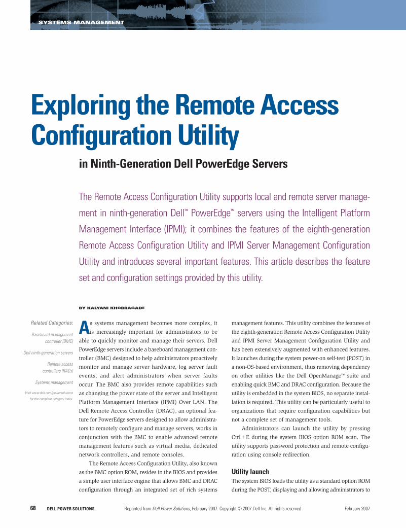
configure BMC and DRAC settings. The utility loads the initialization
module, which displays the BMC banner and prompts the administra-
tor to enter the setup module by pressing Ctrl+E within 5 seconds.
Administrators can skip the five-second wait period and the setup
module by pressing Esc or the space bar. If the administrator does
not press Ctrl+E within five seconds, the POST automatically skips
the setup module.
Initialization module
By default, the initialization module performs BMC initialization
tasks and displays BMC information in the BMC banner. After estab-
lishing communication with the firmware, it also displays the BMC
communication failure check; the BMC, DRAC, backplane, and flex
bay versions; the cable errors check; and emergency management
port settings. Figure 1 shows the information displayed by the ini-
tialization module during the POST.
BMC communication failure checkDuring initialization, the utility attempts to determine whether BMC
communication is reliable by issuing IPMI communication. If this
communication fails, the utility displays the message “BMC Commu-
nication Failure” and does not provide the Ctrl+E launch option.
BMC, DRAC, backplane, and flex bay versionsIf the IPMI communication with the BMC is successful, the utility
displays the BMC firmware version by default. If it detects a DRAC,
backplane, or flex bay, the BMC tries to communicate with them;
on successful communication, the utility displays the corresponding
firmware revisions. If the backplane or flex bay are in boot block
mode or the versions do not match and must be upgraded to the
latest version, the utility displays the warning message “Backplane
firmware is out-of-date. Please update to the latest firmware.”
Cable errors checkSerial Attached SCSI (SAS) cables should be connected using a
valid SAS cable configuration. Otherwise, the initialization module
displays a separate message for each cable error—for example,
“SAS A Cable Missing/Misconfigured,” “SAS B Cable Missing/
Misconfigured,” “Flex Bay Cable Missing/Misconfigured,” or “Flex
Bay Power Cable Missing/Misconfigured.” It also displays the mes-
sage “Power down the system and connect the cable correctly.
Details for storage cabling can be found on the system information
label and in the Hardware Owner’s Manual.”
Emergency management port settings This section of the utility displays the current LAN parameter settings.
By default, the initialization module displays the IP address, subnet
mask, and gateway settings as zeros unless the administrator config-
ures these parameters after pressing Ctrl+E. The module then displays
the updated settings during the POST on subsequent reboots.
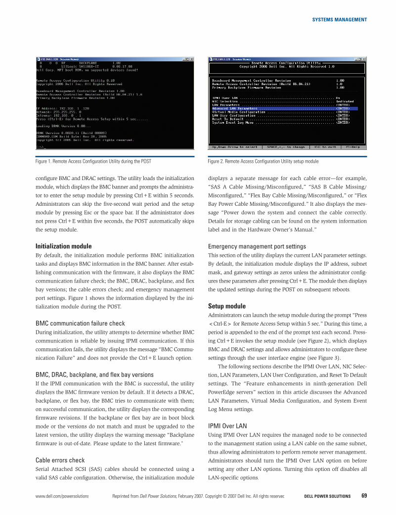
Setup module
Administrators can launch the setup module during the prompt “Press
<Ctrl-E> for Remote Access Setup within 5 sec.” During this time, a
period is appended to the end of the prompt text each second. Press-
ing Ctrl+E invokes the setup module (see Figure 2), which displays
BMC and DRAC settings and allows administrators to configure these
settings through the user interface engine (see Figure 3).
The following sections describe the IPMI Over LAN, NIC Selec-
tion, LAN Parameters, LAN User Configuration, and Reset To Default
settings. The “Feature enhancements in ninth-generation Dell
PowerEdge servers” section in this article discusses the Advanced
LAN Parameters, Virtual Media Configuration, and System Event
Log Menu settings.
IPMI Over LANUsing IPMI Over LAN requires the managed node to be connected
to the management station using a LAN cable on the same subnet,
thus allowing administrators to perform remote server management.
Administrators should turn the IPMI Over LAN option on before
setting any other LAN options. Turning this option off disables all
LAN-specific options.
Figure 1. Remote Access Configuration Utility during the POST Figure 2. Remote Access Configuration Utility setup module
SYSTEMS MANAGEMENT
DELL POWER SOLUTIONS Reprinted from Dell Power Solutions, February 2007. Copyright © 2007 Dell Inc. All rights reserved. February 200770
NIC SelectionThe NIC Selection option includes three settings: Shared, Failover,
and Dedicated. If a DRAC is not present or does not respond to
BMC commands, the Dedicated setting is hidden; if a DRAC is
present, this field uses the Dedicated setting by default. When a
DRAC is present, all network communication is managed by the
DRAC instead of the BMC.
Ninth-generation Dell servers have two embedded network
interface cards (NICs). Administrators can use these NICs for
server management in two configurations based on the Shared
and Failover settings. The Shared setting configures the BMC or
DRAC to transmit and receive network packets using NIC1 and
only receive packets using NIC2. If NIC1 fails, then the remote
management station cannot communicate with the server. Admin-
istrators may want to choose this setting if they are using only
one NIC for server management.
The Failover setting provides communication over both NICs.
Administrators can choose this setting when using both NICs for
server management and when they want server management con-
nectivity even if one NIC fails. In this mode, the BMC or DRAC
receives network packets using NIC1 and NIC2, but only transmits
packets using NIC1. If NIC1 fails, then NIC2 begins transmitting
and receiving; when NIC1 resumes, it will only receive. If NIC2
then fails, NIC1 begins transmitting and receiving again, and when
NIC2 resumes, it will only receive.
LAN Parameters The LAN Parameters settings include RMCP+ Encryption Key, IP
Address Source, Ethernet IP Address, MAC Address, Subnet Mask,
Default Gateway, VLAN Enable, VLAN ID, VLAN, LAN Alert Enabled,
Alert Policy Entry 1, Alert Destination 1, and Host Name String.
RMCP+ Encryption Key. The IPMI 2.0 enhanced authentica-
tion option enables administrators to connect to the server using a
Remote Management Control Protocol+ (RMCP+) key. If the key
is specified in this field, administrators must provide the key to
communicate remotely with the BMC and DRAC.
IP Address Source. Before a computer connects to a network, it
must obtain an address that uniquely identifies it—either a Dynamic
Host Configuration Protocol (DHCP) or a configurable (static) IP
address. This field is read during the POST and updated whenever
administrators choose the Reset To Default option. The default
settings are initialized to “Unknown” and allow administrators to
select the desired source.
Ethernet IP Address, MAC Address, Subnet Mask, and
Default Gateway. Administrators must configure the IP address,
subnet mask, and gateway according to their network requirements
and settings. Certain values are invalid under IP rules—for example,
the utility limits addresses to values under 255.255.255.255. IP
addresses must also comply with the following rules:
• The first octet must be between 1 and 223, but cannot be
127 (for example, 143.xxx.xxx.xxx, where xxx is a number
between 0 and 255). • The last octet must not be 0 or 255 (that is, xxx.xxx.xxx.0 or
xxx.xxx.xxx.255).
The MAC Address field is a read-only field showing the Media
Access Control (MAC) address for the BMC NIC.
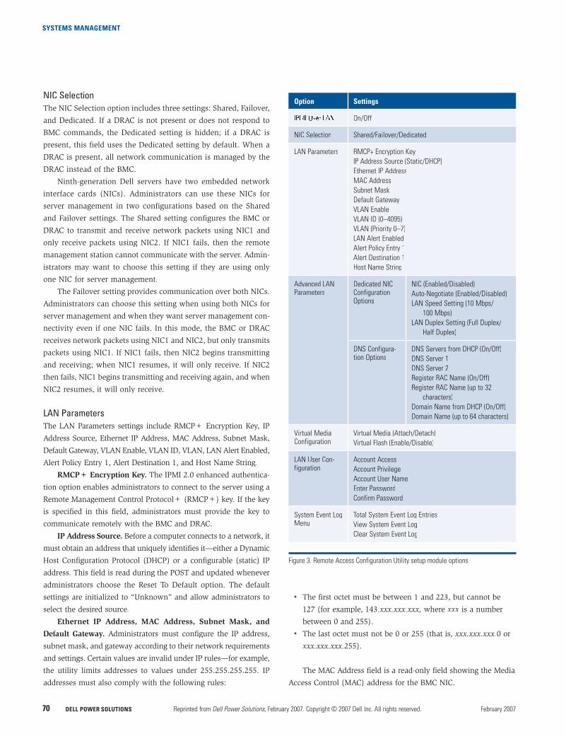
Option Settings
On/Off
NIC Selection Shared/Failover/Dedicated
LAN Parameters RMCP+ Encryption Key
IP Address Source (Static/DHCP)
Ethernet IP Address
MAC Address
Subnet Mask
Default Gateway
VLAN Enable
VLAN ID (0–4095)
VLAN (Priority 0–7)
LAN Alert Enabled
Alert Policy Entry 1
Alert Destination 1
Host Name String
Advanced LAN Parameters
Dedicated NICConfiguration Options
NIC (Enabled/Disabled)
Auto-Negotiate (Enabled/Disabled)
LAN Speed Setting (10 Mbps/
100 Mbps)
LAN Duplex Setting (Full Duplex/
Half Duplex)
DNS Configura-tion Options
DNS Servers from DHCP (On/Off)
DNS Server 1
DNS Server 2
Register RAC Name (On/Off)
Register RAC Name (up to 32
characters)
Domain Name from DHCP (On/Off)
Domain Name (up to 64 characters)
Virtual MediaConfiguration
Virtual Media (Attach/Detach)
Virtual Flash (Enable/Disable)
LAN User Con-figuration
Account Access
Account Privilege
Account User Name
Enter Password
Confirm Password
System Event LogMenu
Total System Event Log Entries
View System Event Log
Clear System Event Log
Figure 3. Remote Access Configuration Utility setup module options
SYSTEMS MANAGEMENT
DELL POWER SOLUTIONS Reprinted from Dell Power Solutions, February 2007. Copyright © 2007 Dell Inc. All rights reserved. February 200772
VLAN Enable, VLAN ID, and VLAN. The virtual LAN (VLAN)
fields allow the creation of independent logical networks within a
physical network, helping simplify the creation of sub-networks.
The settings should conform to the IEEE 802.1Q specification. The
ability to move clients to different broadcast domains by setting
membership profiles for each port on centrally managed switches
is one of the main advantages of 802.1Q VLANs. Although manage-
ment stations and servers can be located anywhere on a network,
they are grouped together by VLAN technology, and broadcasts are
sent to devices within the VLAN.
LAN Alert Enabled, Alert Policy Entry 1, Alert Destination 1,
and Host Name String. Because of the possibly critical nature of
alerts, administrators can configure servers to send Simple Net-
work Management Protocol (SNMP) traps to a remote destination.
Administrators can configure alert settings to indicate sensor states
to the client system (the management station) specified in the Alert
Destination 1 field. Alert severities include critical, warning, and
informational. Traps are sent to this destination only when the LAN
Alert Enabled setting is turned on.
Platform Event Traps (PETs) originating from the firmware
may contain up to 48 bytes of an original equipment manufacturer
(OEM) ASCII string appended to the OEM section of the PET. This
string typically contains a unique description of the host server
contained in the Host Name String setting.
LAN User ConfigurationThe LAN User Configuration settings include Account Access,
Account Privilege, Account User Name, Enter Password, and Con-
firm Password.
Account Access and Account Privilege. These fields allow
administrators to permit specific users to access the servers with a
defined privilege level. Users can take actions remotely based on
their privilege settings.
Account User Name, Enter Password, and Confirm Password.
Administrators can change the username and password for the default
administrator account, UserID2, as defined by the IPMI specification.
The utility assumes this account will always be enabled and have
administrative privileges. A successful password change requires
the administrator to reenter the password for confirmation. If the
administrator does not reenter the password correctly, the password
will not be changed.
Reset To DefaultDell firmware supports resetting certain nonvolatile settings to
the factory defaults. No password or authentication is required
to issue the Reset To Default command, because all local commu-
nication is assumed to have administrative privileges. To protect
against accidental resetting, the utility provides a cancel option
as the default state.
Feature enhancements in ninth-generation
Dell PowerEdge servers
In addition to the features described in the “Setup module” section
in this article, the Remote Access Configuration Utility includes
enhanced capabilities such as password authentication, a DRAC
feature set (the Advanced LAN Parameters and Virtual Media Con-
figuration settings), and the System Event Log Menu settings.
Password authenticationThe entire setup module can be password protected for enhanced
security. The setup password cannot exceed 32 characters. If admin-
istrators have enabled this feature in the BIOS, the utility queries
for the password. Following successful password verification, the
administrator has access to all fields; if the password is not entered
successfully in three attempts, the utility limits all fields to read-only
status. Note: Once in this read-only mode, the utility cannot query
for the password again. If administrators want to enter the password
to gain full access, they must reboot the server.
If the administrator presses the Esc key during password entry,
all fields are disabled. Administrators cannot change the password
within the utility. Once disabled, the field values are visible but
not changeable.
DRAC feature setFor ninth-generation Dell PowerEdge servers, the DRAC no longer
resides on the PCI bus. Because of this change, ninth-generation
Dell server BIOSs no longer include the DRAC option ROM Ctrl+D
option to read and configure DRAC settings. Instead, administrators
can carry out DRAC configuration using the BMC option ROM.
During initialization, the BMC tries to establish a connection to
the DRAC. If the DRAC does not respond to BMC commands within
three tries, the BMC considers the DRAC missing and hides all
DRAC-specific components in the utility. When a DRAC is detected,
the utility exposes the Advanced LAN Parameters and Virtual Media
Configuration settings (see Figure 4).
Advanced LAN Parameters. Administrators should keep in
mind that the NIC integrated in the DRAC cannot be used for OS
network traffic; it can be used only to communicate with the DRAC
to perform management functions.
Based on the DRAC presence signal, the BMC reads the DRAC
revision, NIC settings, and Domain Name System (DNS) settings. Any
changes are saved to the DRAC when the administrator saves and
exits. If the commands fail, the utility continues the POST but displays
the message “BMC Communication Error.” Remote users are allowed
to communicate with the DRAC based on these settings.
Virtual Media Configuration. The Virtual Media Configura-
tion option, which includes the Virtual Media and Virtual Flash
features, helps administrators use data center resources efficiently
and maximize the power and manageability of server environments.
SYSTEMS MANAGEMENT
www.dell.com/powersolutions Reprinted from Dell Power Solutions, February 2007. Copyright © 2007 Dell Inc. All rights reserved. DELL POWER SOLUTIONS 73
Administrators can control the OS and BIOS of servers remotely
using virtual media access.
The Virtual Media feature creates a connection between stor-
age media devices on the client system (the management station)
and the target platform (Dell PowerEdge servers). This feature is
particularly useful when remotely installing BIOS and firmware or
OS components. The DRAC virtual media capabilities are designed
to enable organizations to access remote media such as CDs, DVDs,
ISO images and floppy disks, USB keys, and floppy images through
the host as though they were physically present on the system. The
server identifies these drives during OS boot and after the OS is
completely booted.
The options available under the Virtual Media setting are
Attach and Detach. Because the DRAC in ninth-generation Dell
servers (DRAC 5) supports virtual media implementation based
on USB, it supports seamless attach and detach operations for
virtual media devices. The Attach option attaches virtual media
devices to the USB bus, after which the devices are available
to administrators. The Detach option removes all virtual media
devices from the USB bus.
The DRAC 5 also supports virtual flash (USB key) in its virtual
media implementation. The Virtual Flash feature is particularly
useful because it does not require external client connections or
devices to be functional in the host server. Currently the virtual flash
size is 16 MB; it appears as an unformatted removable USB drive
in the host environment. The USB flash is disabled by default. The
Virtual Flash feature allows virtual flash media to be attached to
the server as if it were physically located on the server. The Enable
option allows the virtual flash to be available for use if virtual
media is attached. The Disable option causes the virtual flash to
be removed and makes it unavailable for use. Note: Enabling and
disabling this feature causes all virtual media devices to be detached
from and attached to the USB bus, meaning that the detach and
attach operations interfere with data read/write operations from
virtual media devices on the server.
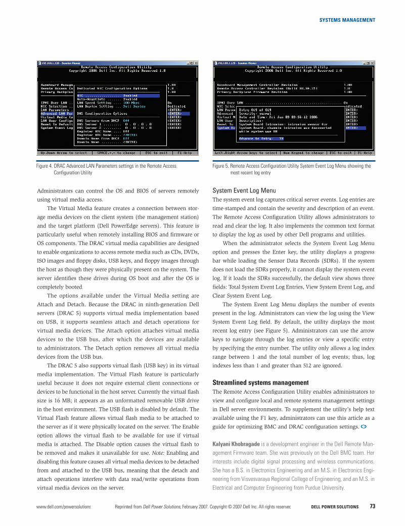
System Event Log MenuThe system event log captures critical server events. Log entries are
time-stamped and contain the severity and description of an event.
The Remote Access Configuration Utility allows administrators to
read and clear the log. It also implements the common text format
to display the log as used by other Dell programs and utilities.
When the administrator selects the System Event Log Menu
option and presses the Enter key, the utility displays a progress
bar while loading the Sensor Data Records (SDRs). If the system
does not load the SDRs properly, it cannot display the system event
log. If it loads the SDRs successfully, the default view shows three
fields: Total System Event Log Entries, View System Event Log, and
Clear System Event Log.
The System Event Log Menu displays the number of events
present in the log. Administrators can view the log using the View
System Event Log field. By default, the utility displays the most
recent log entry (see Figure 5). Administrators can use the arrow
keys to navigate through the log entries or view a specific entry
by specifying the entry number. The utility only allows a log index
range between 1 and the total number of log events; thus, log
indexes less than 1 and greater than 512 are ignored.
Streamlined systems management
The Remote Access Configuration Utility enables administrators to
view and configure local and remote systems management settings
in Dell server environments. To supplement the utility’s help text
available using the F1 key, administrators can use this article as a
guide for optimizing BMC and DRAC configuration settings.
Kalyani Khobragade is a development engineer in the Dell Remote Man-
agement Firmware team. She was previously on the Dell BMC team. Her
interests include digital signal processing and wireless communications.
She has a B.S. in Electronics Engineering and an M.S. in Electronics Engi-
neering from Visvesvaraya Regional College of Engineering, and an M.S. in
Electrical and Computer Engineering from Purdue University.
Figure 4. DRAC Advanced LAN Parameters settings in the Remote Access
Configuration Utility
Figure 5. Remote Access Configuration Utility System Event Log Menu showing the
most recent log entry