explosion effectsexplosion effects - · pdf file– high peak load is acceptable if...
TRANSCRIPT

Explosion EffectsExplosion Effects
Joseph E ShepherdJoseph E ShepherdCalifornia Institute of Technology
Pasadena, CA USA 91125Joseph E Shepherd@caltech [email protected]
Presented at
The Fourth European Summer School on Hydrogen SafetyCoralia Marina Viva, Corsica, France
7th – 16th September 2009,
7 Sept 2009 Shepherd - Explosion Effects 1

TopicsA. IntroductionB. Ideal Blast WavesB. Ideal Blast WavesC. Mechanics and Strength of MaterialsD Modes of Structural ResponseD. Modes of Structural ResponseE. Modeling Structural ResponseF Blast Loading Dynamic Reponse – Cantilever BeamF. Blast Loading Dynamic Reponse – Cantilever BeamG. Internal Explosions – Deflagrations and DetonationsH ReferencesH. References
7 Sept 2009 Shepherd - Explosion Effects 2

Introduction
Explosions create high-pressure, high-temperature gases that can cause:p g p , g p g
1. Mechanical failure due to pressure or blast waves or internal pressure build-up.1. Permanent deformation or equipment or structures2 Rupture or tearing of metal or building components2. Rupture or tearing of metal or building components3. Creating flying fragments or missiles4. Blast, fragment or impact injury
2. Thermal failure due to heat transfer from fireball or hot combustion products.1. Softening of metal structures2. Ignition of building materials, electrical insulation, plastic or paper products3 Burn injuries to skin and eyes3. Burn injuries to skin and eyes
3. Combination of fire and explosion, thermal and mechanical effects often occur.
7 Sept 2009 Shepherd - Explosion Effects 3

Mechanical effects from high pressure• Expansion of combustion products
due to conversion of chemical to thermal energy in combustion andthermal energy in combustion and creation of gaseous products in high explosives
• Expansion ratio for gaseous• Expansion ratio for gaseous explosions depends on thermodynamics
• Expansion rate depends on• Expansion rate depends on chemical kinetics and fluid mechanics– Flame speedsFlame speeds – Detonation velocity
7 Sept 2009 Shepherd - Explosion Effects 4

Thermal effects from high temperature
• Hot gases radiate strongly in IR, particularly for sooting explosion like BLEVE.p– Fireballs cause injury (skin burns) and secondary ignition of structures
• Internal explosions create high-speed gas and convective heat t f i dditi t IR di titransfer in addition to IR radiation– Heat up equipment, ignite flammable materials
7 Sept 2009 Shepherd - Explosion Effects 5

Fragment effects from structural failure
• Primary fragments– Created by rupture of vessel or structure– Some fraction of explosion energy transferred to fragment– Some fraction of explosion energy transferred to fragment– Follows a ballistic trajectory
• Secondary fragments– Created by blast wave and following flow– Accelerated by flow, eventually follows a ballistic trajectory
• Both lift and drag important in determining trajectories7 Sept 2009 Shepherd - Explosion Effects 6
• Both lift and drag important in determining trajectories

Pasadena TX 1989 – C2H4 Flixborough 1974 - cyclohexane
(20 Kg H2 )(20 Kg H2 )
7 Sept 2009 Shepherd - Explosion Effects 7Port Hudson 1974 – C3H8

Pasadena TX 1989
7 Sept 2009 Shepherd - Explosion Effects 8

Nuclear Blast Wave Damage – 5 psi (34 kPa)
7 Sept 2009 Shepherd - Explosion Effects 9

Effects of High Explosive Detonation
7 Sept 2009 Shepherd - Explosion Effects 10

Truck Bomb – 4000 lb TNTe
7 Sept 2009 Shepherd - Explosion Effects 11

Response of a Large Structure is Complex!Bl t ff t ll b f l d• Blast effects cause a small number of columns and slabs to directly fail
• Increased load on other structural elements leads to• Increased load on other structural elements leads to progressive collapse
• In Murrah Building, 40% of floor area destroyed due g, yto progressive collapse, only 4% due to direct blast.
• Factors in progressive collapse– Building design (seismic resistance can help)– Fires can weaken structural elements (WTC)
• Detailed analysis and testing is needed to• Detailed analysis and testing is needed to understand or predict response
7 Sept 2009 Shepherd - Explosion Effects 12

Preview – Structural Response Analysis• First, estimate static capacity of structure. Failure can occur to do either
– Excessive stress – plastic deformation or fracture makes structure too weak for service
– Excessive deformation – structure not useable due to leaks in fittings or misfit of components (rotating shafts, etc).
• Second, what are structural response times?• Large spectrum for a complex structureg p p• Single value for simple structure
– How do these compare to loading and unloading times of pressure wave?• Loading time• Unloading timeUnloading time
• Third, estimate dynamic peak deflection and stresses based on response times and loading history– High peak load is acceptable if duration is short (impulsive case)
L k l d li it if d ti i l d idl li d ( dd )– Lower peak load limit if duration is long and rapidly applied (sudden case)
7 Sept 2009 Shepherd - Explosion Effects 13

Structural Response
• Structures move in response to forces (Newton’s Law)Law)– Structure has mass and stiffness– Structure “pushes back”p
7 Sept 2009 Shepherd - Explosion Effects 14

Determining structural loads
• Load generally means “applied force” in this context The primary load is usually thought of ascontext. The primary load is usually thought of as due to pressure differences created by the explosion process. Pressure differences across p pcomponents of a structure create forces on the structure and internal stresses.
• Three simple cases– External explosion– Blast wave interaction– Internal explosion
7 Sept 2009 Shepherd - Explosion Effects 15

External Explosion• Explosion due to accidental
vapor cloud release and ignition source starting a g gcombustion wave
• Flame accelerates due to instabilities and turbulence due t fl f ilit t tto flow over facility structures
• Volume displacement of combustion (“source of volume”) compresses gas and createscompresses gas and creates motion locally and at a distance– Blast wave propagates away
from source
Unconfined Vapor Cloud Explosion (UVCE)
7 Sept 2009 Shepherd - Explosion Effects 16

Blast Wave Interaction
• Blast wave consists of– Leading shock frontg– Flow behind front
• Pressure loading I id t d fl t d– Incident and reflected pressure behind shock
– Stagnation pressure from flow
• Factors in loading– Blast decay time– Diffraction timeDiffraction time– Distance from blast origin
7 Sept 2009 Shepherd - Explosion Effects 17

Internal Explosion
• Can be deflagration or detonationf• Deflagration
– Pressure independent of position, slow• Detonation
– Spatial dependence of pressure– Local peak associated with detonation wave formation
and propagation
7 Sept 2009 Shepherd - Explosion Effects 18
p p g

Loading Histories• Pressure-time histories can be derived
from several sources– Experimental measurements Slow flame in vessel– Analytical models with thermodynamic
computation of parameters– Detailed numerical simulations using
computation fluid dynamics High speed flame in vesselcomputation fluid dynamics– Empirical correlations of data– Approximate numerical models of blast
wave propagation (Blast-X)
High speed flame in vessel
• Characterizing pressure-time histories– Single peak or multiple peaks
Nonideal explosion– Rise time– Peak pressure– Duration
Nonideal explosion
7 Sept 2009 Shepherd - Explosion Effects 19Ideal blast wave

Ideal Blast WavesIdeal Blast Waves
7 Sept 2009 Shepherd - Explosion Effects 20

Ideal Blast Wave SourcesSimplest form of pressure loading – due concentrated, rapid release of energyHigh explosive or “prompt” gaseous detonation. Main shock wave followed bypressure wave and gas motion, possibly secondary waves.
Inside Explosion
7 Sept 2009 Shepherd - Explosion Effects 21Pfortner

Blast Wave from Hydrogen-Air Detonation
Outside explosionexplosion
Shepherd 1986Shepherd 1986
7 Sept 2009 Shepherd - Explosion Effects 22

Blast and Shock Waves
• Leading shock front pressure jump determined by wave speed – shock Mach number.
• Gas is set into motion by yshock then returns to rest
• Wave decays with distance• Loading determined by• Loading determined by
– Peak pressure rise– Impulse
P iti d ti h– Positive and negative phase durations
Specific impulse!
7 Sept 2009 Shepherd - Explosion Effects 23
p p

Scaling Ideal Blast Waves I.
• Dimensional analysis (Hopkinson 1915, Sachs 1944, Taylor-Sedov))– Total energy release E = Mq
• M = mass of explosive atmosphere (kg)• q = specific heat of combustion (J/kg)q specific heat of combustion (J/kg)
– Initial state of atmosphere Po or o and co
• Limiting cases– Strength of shock wave
• Strong P >> Po
• Weak P << Po
– Distance from source• Near R ~ Rsource
• Far R >> Rsource
7 Sept 2009 Shepherd - Explosion Effects 24
source

Scaling Ideal Blast Waves II.• Scale parameters
– Blast length scale Rs = (E/Po)1/3
– Time scale Ts = Rs/co
– Pressure scaleCl t l i P ( ll b d d b P )• Close to explosion Pexp (usually bounded by PCJ)
• Far from explosion Po
• Nondimensional variables Relationships:Nondimensional variables– pressure P/Po
– distance R/Rs
Relationships:
P = Po F(R/Rs)
I P T G(R/R )s
– time t/Ts
– Impulse (specific) I/(Po Ts)
I = Po Ts G(R/Rs)
7 Sept 2009 Shepherd - Explosion Effects 25

Cube Root Scaling in Standard atmosphere
• Simplest expression of scaling (Hopkinson)– At a given scaled range R/M1/3, you will have the same
scaled impulse I/M1/3 and overpressure P– When you increase the charge size by K, overpressure will
remain constant at a distance KR, and the duration and arrival time will increase by K
7 Sept 2009 Shepherd - Explosion Effects 26
arrival time will increase by K.

TNT EquivalentId l bl t f l i i l t t th t• Ideal blast wave from gaseous explosion equivalent to that from High Explosive (TNT) when energy of gaseous explosive is correctly choseny
• Universal blast wave curves in far field when expressed in Sachs’ scaled variables
• For ideal gas explosions (detonations) E is some fixed fraction• For ideal gas explosions (detonations) E is some fixed fraction of the heat of combustion (Q = qM)
• For nonideal gas explosions (unconfined vapor clouds), E is g p ( p )quite a bit smaller. Key issues:– How to correctly select energy equivalence?– How to correctly treat near field?
7 Sept 2009 Shepherd - Explosion Effects 27
– How to correctly treat near field?

Energy Equivalent for Common ExplosivesExplosive Q (MJ/kg) Density
(g/cc)CJ velocity (km/s)
CJ Pressure (kb )(kbar)
TNT 4.52 1.6 6.7 210RDX 5 36 1 65 8 7 340RDX 5.36 1.65 8.7 340HMX 5.68 1.9 9.1 390Tetryl 4 52 1 73 7 85 260Tetryl 4.52 1.73 7.85 260C6H14 45 (1.62) 0.66 1.8 0.018H2 100 (2.7*) 8.2E-5 1.97 0.015( )
Values from Baker et al.* For fuel air mixture
7 Sept 2009 Shepherd - Explosion Effects 28
* For fuel-air mixture

Scaling of Blast Pressure – Ideal Detonation
Comparison of fuel-air bag tests to high explosivesbag tests to high explosives
Work done at DRES (Suffield, CANADA) in 1980s
Moen et al 1983
7 Sept 2009 Shepherd - Explosion Effects 29

Scaling of Impulse – Ideal Detonation
Surface burst
Air burstMoen et al 1983
7 Sept 2009 Shepherd - Explosion Effects 30
For the same overpressure or scaled impulse at a given distance, M(surface) = 1/2 M(air)

Energy scaling of H2-air blast
Energy Equivalence
100 MJ/kg of H2
or
2 71 MJ/kg of fuel-air2.71 MJ/kg of fuel-air mix for stoichiometric.
Shepherd 1986
7 Sept 2009 Shepherd - Explosion Effects 31

Hydrogen-air Detonation in a Duct
• Blast waves in ducts decay much more slowly than yunconfined blasts
P ~ x-1/2
M ltiple shock a es• Multiple shock waves created by reverberation of transverse waves within duct
• Pressure profile approaches triangular waveshape attriangular waveshape at large distances.
7 Sept 2009 Shepherd - Explosion Effects 32Thibault et al 1986

Interaction of Blast Waves with Structures
Blast-wave interactions with multiple structures LHJ Absil, AC van den Berg, J. Weerheijm p. 685 - 290,Sh k W V l 1 Ed St t tShock Waves, Vol. 1, Ed. Sturtevant, Hornung, Shepherd, World Scientific, 1996.
7 Sept 2009 Shepherd - Explosion Effects 33

Idealized Interactions
Enhancement depends:
Incident wave strength
Angle of incidence
7 Sept 2009 Shepherd - Explosion Effects 34
“Explosions in Air” Baker

Nonideal Explosions
• Blast pressure depends on magnitude of maximum flame speedspeed
• Flame speed is a function of– Mixture composition
T b l l l– Turbulence level– Extent of confinement
• There is no fixed energy equivalent– E varies from 0.1 to 10% of Q
• Impulse and peak pressure depend on flame speed and size of cloud – Sachs’ scaling has to be expanded to include theseg p
7 Sept 2009 Shepherd - Explosion Effects 35

Pressure Waves from Fast FlamesSachs’ scaling with addition parameter – effective flame Mach number Mf. Numericalsimulations based on ‘porous piston’ model and 1-D gas dynamics.
Tang and Baker 1999
7 Sept 2009 Shepherd - Explosion Effects 36

What is Effective Flame Speed?
Consider volume displacementof a wrinkled (turbulent) flame growing in( ) g ga mean spherical fashion.
Expansionratio
Dorofeev 2006
7 Sept 2009 Shepherd - Explosion Effects 37
Dorofeev 2006

Mechanics and Strength of MaterialsMechanics and Strength of Materials
7 Sept 2009 Shepherd - Explosion Effects 38

Forces, Stresses and Strains
• Loading becomes destructive when forces are sufficient to displace structures that are not anchoredsufficient to displace structures that are not anchored or else the forces (or thermal expansion) create stresses that exceed yield strength of the material. y g
• Important cases– Rigid body motion – fragments and overturningg y g g– Deformation due to internal stresses
• Bending, beams and platesM b t l• Membrane stresses, pressure vessels
7 Sept 2009 Shepherd - Explosion Effects 39

Rigid Body Forces due to Explosion
• Pressure varies with position and time over surface – has to be measured or computed
• Local increment of force on surface due to pressure only p yin high Reynolds’ number flow
Geometry and distribution of pressure will result in moments as well as forces! Be sure to add in contributions from body
7 Sept 2009 Shepherd - Explosion Effects 40
yforces (gravity) to get total force.
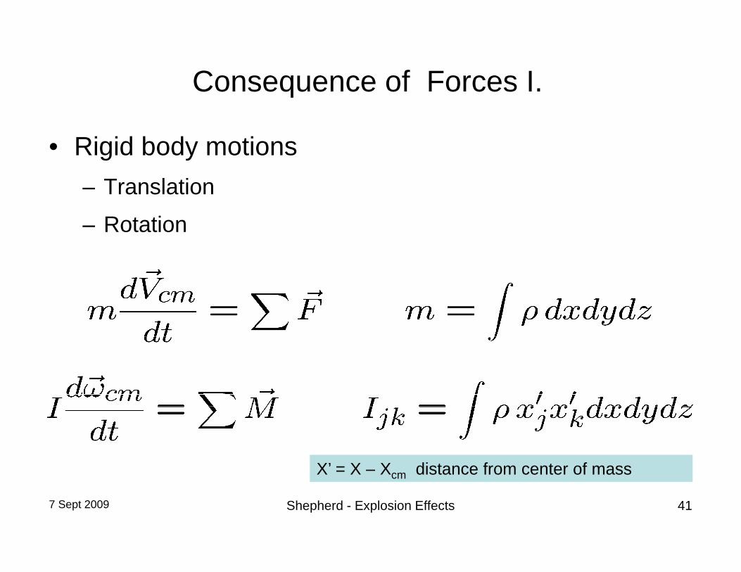
Consequence of Forces I.
• Rigid body motions– Translation
– Rotation
X’ = X X distance from center of mass
7 Sept 2009 Shepherd - Explosion Effects 41
X = X – Xcm distance from center of mass

Internal Forces Due to an Explosion
• Force on a surface element dS
• Stress tensor Stress tensor
7 Sept 2009 Shepherd - Explosion Effects 42

Consequence of forces – small strains (<0.2 %)
• Elastic deformation • Elastic strainElastic strain
• Elastic shear
Youngs’ modulus E, shear modulus E, and Poisson ratio are material properties
7 Sept 2009 Shepherd - Explosion Effects 43

Consequences of forces – large strains
• Onset of yielding for ~ YY
• Necking occurs in plastic regime > Y
• Plastic instability and rupture for > u
• Energy absorption byEnergy absorption by plastic deformation
Plot is in terms of engineering stress and strain, apparentmaximum in stress is due to area reduction caused by necking
7 Sept 2009 Shepherd - Explosion Effects 44

Stress-Strain Relationships
7 Sept 2009 Shepherd - Explosion Effects 45

Yield and Ultimate Strength
• Yield point YP determined by uniaxial tension test• Yielding is actually due to stress differences or shearYielding is actually due to stress differences or shear.
Extension of tension test to multi-axial loading:– Maximum shear stress model max < YP/2
V Mi t h d l h t it i– Von Mises or octahedral shear stress criterion
• Onset of localized permanent deformation occurs well before complete plastic collapse of structure occurs.
7 Sept 2009 Shepherd - Explosion Effects 46

Some Typical Material Properties
E G y u ruptureMaterial (kg/m3) (GPa) (GPa) (MPa) (MPa)Aluminum 6061-T6 2.71 x 10³ 70 25.9 0.351 241 290 0.05Aluminum 2024-T4 2.77 x 10³ 73 27.6 0.342 290 441 0.3Steel (mild) 7.85 x 10³ 200 79 0.266 248 410-550 0.18-0.25Steel stainless 7 6 x 10³ 190 73 0 31 286 500 760 1280 0 45 0 65Steel stainless 7.6 x 10 190 73 0.31 286-500 760-1280 0.45-0.65Steel (HSLA) 7.6 x 10³ 200 0.29 1500-1900 1500-2000 0.3-0.6Concrete 7.6 x 10³ 30-50 20-30 - 0Fiberglass 1.5-1.9 x 10³ 35-45 - 100-300 -Polycarbonate 1 2-1 3 x 10³ 2 6 55 60Polycarbonate 1.2-1.3 x 10 2.6 55 60 -PVC 1.3-1.6 x 10³ 0.2-0.6 45-48 - -Wood 0.4-0.8 x 10³ 1-10 - 33-55 -Polyethylene (HD) 0.94-0.97 x 10³ 0.7 20-30 37 -
7 Sept 2009 Shepherd - Explosion Effects 47

Considerations about material properties
• Simple models: – perfectly plastic
perfectly plastic, – elastic perfectly plastic
• More realistic models
ddt
– Strain hardening Y ()
– Strain rate effects (d/dt)
– Strain rate effects, Y(d/dt)
– Temperature effects (T)
Temperature effects Y(T)
7 Sept 2009 Shepherd - Explosion Effects 48

Modes of Structural ResponseModes of Structural Response
7 Sept 2009 Shepherd - Explosion Effects 49

Mechanism of Structural Deformation
• Stress waves– Longitudinal or transverseLongitudinal or transverse– Short time scale
• Flexural waves– Shock or detonation propagation inside tubes– Vibrations in shells
t i i• tension or compression– Deforms shells
• shearing loads• shearing loads– Bends beams and plates
7 Sept 2009 Shepherd - Explosion Effects 50

Pressure Loading Characterization
P
• Structural response time T vs. loading and unloading time scales• Peak pressure P vs. Capacity of structure• Loading regimesg g
– Slow (quasi-static), typical of flame inside vessels T << L or u– Sudden, shock or detonation waves L << T
• Short duration – Impulsive U << T• Long duration - Step load T <<
7 Sept 2009 Shepherd - Explosion Effects 51
• Long duration - Step load T << U

Statics vs. Dynamics
• Static loading T << l, uLoading and unloading times long compared to– Loading and unloading times long compared to characteristic structural response time
– Inertia unimportant– Response determined completely by stiffness, magnitude
of load. • Dynamic loading T ≥ l, u
– Loading or unloading time short compared to characteristic structural response timestructural response time
– Inertia important– Response depends on time history of loading
7 Sept 2009 Shepherd - Explosion Effects 52
p p y g

Static Stresses in Spherical Shell
• Balance membrane stresses with internal pressure ploading
• Force balance on equator R
• Membrane stressR
Membrane stress
7 Sept 2009 Shepherd - Explosion Effects 53
Validate only for thin-wall vessels h < 0.2 R

Static Stresses in Cylindrical Shells
• Biaxial state of stress• Longitudinal stress due toLongitudinal stress due to
projected force on end caps.
• Radial (hoop) stress due to projected force on equatorprojected force on equator
7 Sept 2009 Shepherd - Explosion Effects 54

Bending of Beams
• Force on beam due to integrated effects of gpressure loading
• Pure bending has no net longitudinal stresslongitudinal stress
• Deflection for uniform loading
7 Sept 2009 Shepherd - Explosion Effects 55

Stress Wave propagation in Solids
• Dynamic loading by impact or high explosive detonation in contact with structure• Two main types
– Longitudinal (compression P-waves)Longitudinal (compression, P waves) – Transverse (shear, S-waves
• Stress-velocity relationship (for bar P-waves)Cl exact for barCl exact for bar
7 Sept 2009 Shepherd - Explosion Effects 56

Is direct stress wave propagation important?
• Time scale very fast compared to main structural response T ~ L/C p
Cl (m/s) Cs(m/s)Steel 6100 3205
– Average out in microseconds (10-6 s)
Aluminum 3205 3155
• Stress level low compared to yield stress
~ P ~ 10 MPa << = 200 500 MPa ~ P ~ 10 MPa << Y = 200- 500 MPaDirect stress propagation within the structural elements is usually not relevant for structural response to gaseous explosions. Important for high
l i h t t i l i di t t t ith l i
7 Sept 2009 Shepherd - Explosion Effects 57
explosive when structure is very close or in direct contact with explosive

Vibration of Plates, Beams, & Structures
• Element vibrations– Membranes or shellsMembranes or shells
– Plates or beams
– Modes of flexural motion• Standing waves, frequencies ig i
• Propagating dispersive waves (k)
• Coupled motions of entire structure
7 Sept 2009 Shepherd - Explosion Effects 58

Free Vibration of Clamped Plate
Morse and Ingard Theoretical Acoustics
7 Sept 2009 Shepherd - Explosion Effects 59
Morse and Ingard Theoretical Acoustics
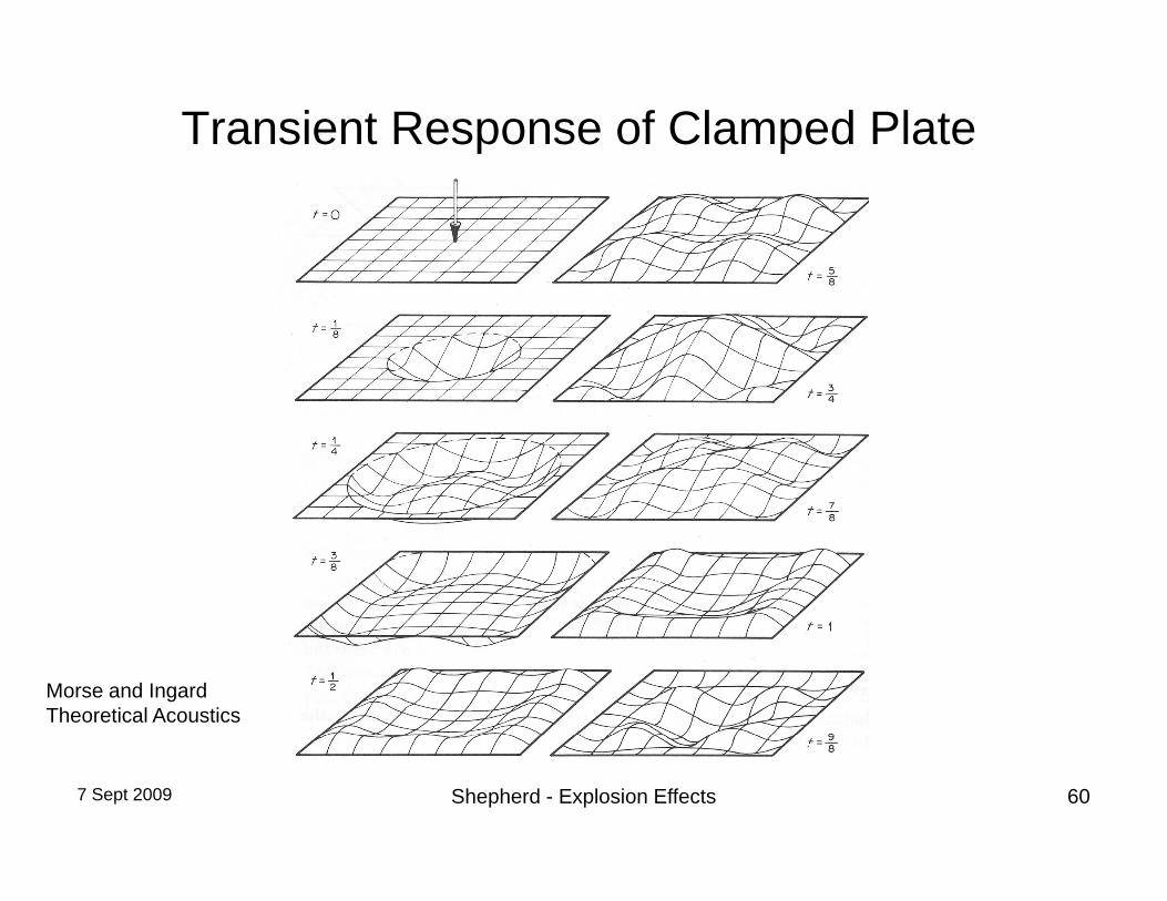
Transient Response of Clamped Plate
Morse and Ingard Theoretical Acoustics
7 Sept 2009 Shepherd - Explosion Effects 60

Two Special Situations
• Loading on small objects– Represent forces as drag coefficients dependent on shape and p g p p
orientation and function of flow speed.F = ½ V2 CD(Mach No, Reynolds No) x Frontal Area
• Thermal stresses• Thermal stresses. – Thermal stresses are stresses that are created by differential thermal
expansion caused by time-dependent heat transfer from hot explosion gases This is distinct from the loss of strength of materials due to bulkgases. This is distinct from the loss of strength of materials due to bulk heating, which is a very important factor in fires which occur over very much longer durations than explosions.
= /E + T = /E + T
7 Sept 2009 Shepherd - Explosion Effects 61

Modeling Structural ResponseModeling Structural Response
7 Sept 2009 Shepherd - Explosion Effects 62

Determining structural response
• IssuesStatic or dynamic– Static or dynamic• depends on time scale of response compared to that of load
– impulsive (short loading duration)( )– sudden (short rise time)
– quasi-static (long rise time)
– Elastic or elastic-plastic• depends on magnitude of stresses and deformation
– yield stress limit appropriate for vessels designed to contain explosions
– maximum displacement or deformation limit appropriate for determining or preventing leaks or rupture under accident conditions
7 Sept 2009 Shepherd - Explosion Effects 63

Simple estimates• Strength of materials approach assuming equivalent static load
– Useful only for very slow combustion (static loads) and negligible thermal load
• Theory of elasticity and analytical solutions– static solutions for many common vessels and components (Roarke’s Handbook)static solutions for many common vessels and components (Roarke s Handbook)– dynamic solutions available for simple shapes – mode shapes and vibrational periods are tabulated.– Energy methods with assumed mode shapes (Baker et al method)– Analytical models for traveling loads available for shock and detonation waves– Transient thermo-elastic solutions available for simple shapes p p
• Theory of plasticity – rigid-plastic solutions available for simple shapes and impulsive loads.– Energy methods can provide quick bounds on deformation
• Empirical correlationsEmpirical correlations– Test data available for certain shapes (clamped plates) and impulsive loads– Pressure-impulse damage criteria have been measured for many items and people subjected to blast loading
• Spring-mass system modelssingle degree of freedom– single degree of freedom
– multi-degree of freedom– elastic vs plastic spring elements
7 Sept 2009 Shepherd - Explosion Effects 64

Simple Structural Models
• Ignore elastic wave propagation within structure• Lump mass and stiffness into discrete elementsp
– Mass matrix M– Stiffness matrix K– Displacements XiDisplacements Xi– Applied forces Fi
• Equivalent to modeling structure as coupled “spring-mass” systemsystem
• Results in a spectrum of vibrational frequencies I corresponding to different vibrational modes– Fundamental (lowest) mode usually most relevant
7 Sept 2009 Shepherd - Explosion Effects 65
Fundamental (lowest) mode usually most relevant

Single Degree of Freedom Models (SDOF)
• Effective mass M• Effective stiffness K• Effective stiffness K• One displacement motion X• Force = mass x accelerationForce mass x acceleration• Equivalent to spring-mass
systemy• Elastic motion is oscillation of
displacement x = X-Xo with period T
7 Sept 2009 Shepherd - Explosion Effects 66T

Forced Oscillation of SDOF system• Blast wave characterized by
– Peak pressure P
p
– Decay time • Forced harmonic oscillator,
t
F(t) = AP(t)
• Response is forced oscillation
7 Sept 2009 Shepherd - Explosion Effects 67

Example of SDOF Modeling
• Radial oscillation of cylindersR
h
P(t)x
• Bending of beams or columns
Frequencies are “lowest or fundamental mode” –these are usually the most important modes forstructural response to explosions.
7 Sept 2009 Shepherd - Explosion Effects 68
structural response to explosions.

Modes of Beam Oscillation
Morse and Ingard Theoretical Acoustics
7 Sept 2009 Shepherd - Explosion Effects 69
Morse and Ingard – Theoretical Acoustics

SODF - Square Pulse
7 Sept 2009 Shepherd - Explosion Effects 70

SDOF -Impulsive Regime• Sudden load application, short
duration of loading << T• Linear scaling between maximum
strain/ displacement and impulse in elastic regime:
• Impulse generates initial velocity
• Energy conservation determinesEnergy conservation determines maximum deflection
7 Sept 2009 Shepherd - Explosion Effects 71

SDOF – Sudden regime
• Quick application of load and long duration >> Tu >> T
• Peak deflection is twice static value for same maximum load
FMax force
time
displacement
7 Sept 2009 Shepherd - Explosion Effects 72
T time
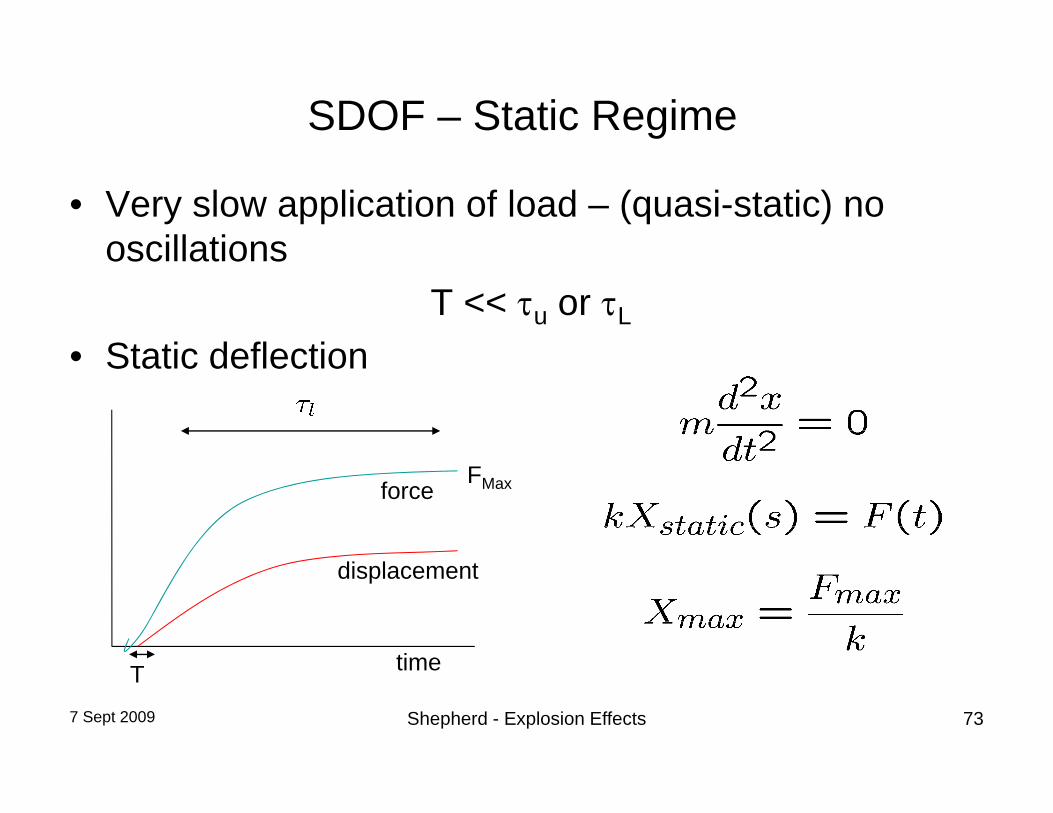
SDOF – Static Regime
• Very slow application of load – (quasi-static) no oscillationsoscillations
T << u or L
• Static deflection• Static deflection
FMaxforce
time
displacement
7 Sept 2009 Shepherd - Explosion Effects 73
T time

SDOF - Dynamic load factor (DLF)S O y a c oad acto ( )
7 Sept 2009 Shepherd - Explosion Effects 74

SDOF - Plasticity
• Replace kX with nonlinear relationship based on flow pstress curve ()
• Energy absorbed by plastic ork is m ch higher thanwork is much higher than
elastic work• Peak deformation for
impulsive load scales with impulse squared.
7 Sept 2009 Shepherd - Explosion Effects 75

Pressure-Impulse (P-I) Structure Response
• More realistic representation of response• For fixed X and pulse shape unique relationFor fixed Xmax and pulse shape, unique relation
between peak pressure (P) and impulse (I)Shock wave with exponential tail
Limiting cases:
1. Short pulse – impulse determines damage
2 L l k2. Long pulse – peak pressure determines
7 Sept 2009 Shepherd - Explosion Effects 76

P-I Damage thresholds IIBrick structures (WWII)
1000Brick structures (WWII)
600
800
a-s)
400
600
Impu
lse
(Pa
50-75% demolished
major damage
200 minor damage
major damage
00 20 40 60 80 100
7 Sept 2009 Shepherd - Explosion Effects 77From Baker et al.Overpressure (kPa)

P-I Damage Thresholds II
Ear drums
7 Sept 2009 Shepherd - Explosion Effects 78

Example• Blast wave from 50 lbs TNT equivalent at 100 ft
range• Use charts or correlations from Dorofeev
E = 4.52x50/2.2 = 103 MJ Rs = (1 x 10⁸ / 105 )1/3 = 10 m or 33 ft
R* = 30.5/10 = 3 P* = 0.085 or P = 1.25 psi (8.5 kPa)
I* = 0.012 T = 3/340 = 8.8 ms I = 10 Pa s
These are “side-on” parameters, normal reflection will approximately doubleoverpressure and impulse in this regime
7 Sept 2009 Shepherd - Explosion Effects 79
overpressure and impulse in this regime.

P-I Results
Brick structures Ear drums
800
1000
400
600
Impu
lse
(Pa-
s)
50-75% demolished
major damage
0
200 minor damage
major damage
00 20 40 60 80 100
Overpressure (kPa)
Your ears will be ringing but the building is undamaged!
7 Sept 2009 Shepherd - Explosion Effects 80

Numerical simulation
• Finite element models• static• static• vibration: mode shape and frequencies• dynamic
– transient response to specified loading– elastic – plastic/fractureplastic/fracture
• Numerical integration of simple models with complex loading historiescomplex loading histories
– spring-mass systems– Elasticity with assumed mode shape
7 Sept 2009 Shepherd - Explosion Effects 81
y p

Blast Loading Dynamic ResponseBlast Loading Dynamic Response
Example: Cantilever Beam
7 Sept 2009 Shepherd - Explosion Effects 82

Blast Incident on a Cantilever Beam
• Blast loading of a cantilever beamcantilever beam
• Forces – Initial impulse of shock– Flow and drag
• Elastic response– Giordona et al
• plastic response– Van Netton and Dewey
7 Sept 2009 Shepherd - Explosion Effects 83

Forces on Blast-loaded Cantilever
• Shock wave interaction– Sudden load to arrival of
shock and propagation around cylinder
– Usually impulsivey p
• Following flow– Continuous load due to
separated flow aroundseparated flow around cylinder.
– Transient drag loading
Van Netten and Dewey Shock Waves (1997) 7: 175 190
7 Sept 2009 Shepherd - Explosion Effects 84
Van Netten and Dewey, Shock Waves (1997) 7: 175–190
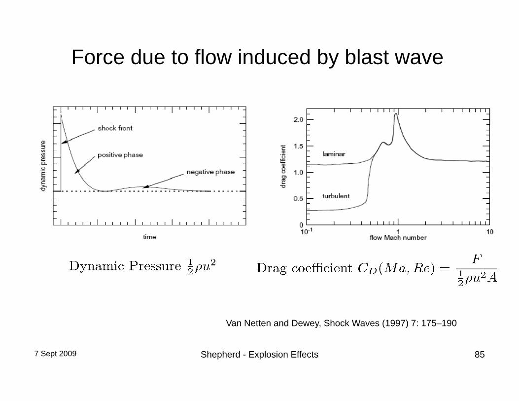
Force due to flow induced by blast wave
Van Netten and Dewey, Shock Waves (1997) 7: 175–190
7 Sept 2009 Shepherd - Explosion Effects 85
y, ( )

Initial stages of shock diffraction over a cantilever beam
Immediately after theImmediately after the shock wave passes over the beam there is no deflection.
Purely elastic case.
Experiment (left)Experiment (left)Computation (right)
7 Sept 2009 Shepherd - Explosion Effects 86
Giordano et al, Shock Waves 14 (1-2), 103-110, 2005.

Later stages of diffraction over a cantilever beam
After some time, the ,beam starts to deform. Dynamic response of beam and inertia are important physical effectsimportant physical effects.
Purely elastic case.
Experiment (left)Computation (right)
7 Sept 2009 Shepherd - Explosion Effects 87Giordano et al, Shock Waves 14 (1-2), 103-110, 2005.

Applied Load and Oscillations of Beam
Note the harmonic motion of thebeam after incident and reflected shock.
7 Sept 2009 Shepherd - Explosion Effects 88Giordano et al, Shock Waves 14 (1-2), 103-110, 2005.

Plastic Deformation of Blast loaded Cantilever
Permanent deformation of beam due to formation of a “plastic hinge” at the base. Stresses exceed the yield strength of the material and beam remains permanentlybeam remains permanently bent over. Deflection depends on loading history.
Can be used as a “blast gage” for ideal explosives.
7 Sept 2009 Shepherd - Explosion Effects 89
Van Netten and Dewey, Shock Waves (1997) 7: 175–190

Shock tube experimentsDeformation of a 200 mm long, 1.55 mm dia aluminum rod due to a M = 1.23 shock, 1 ms intervals
Final angle of deformation for 50 mmlong, 1 mm dia solder rods.
Van Netten and Dewey, Shock Waves (1997) 7: 175–190
7 Sept 2009 Shepherd - Explosion Effects 90

Internal ExplosionsInternal Explosions
Deflagrations and Detonations in Vessels
7 Sept 2009 Shepherd - Explosion Effects 91

Creation of flow by Explosions I.Fl t fl d t i f d t hi• Flames create flow due to expansion of products pushing against confining surfaces
• Consider ignition at the closed-end of a tubeConsider ignition at the closed end of a tube
– Expansion ratiob
u
– Flame velocity effTfTf SAASV /
b
– Flow velocity
ST
effT
effTf SSVU )1(
Burned (u =0) Vf Unburned u > 0
flame
ST
Blast wave
u = 0
7 Sept 2009 Shepherd - Explosion Effects 92

Creation of flow by Explosions II
• Detonations and shock waves create flow due to acceleration by pressure gradients in wavesC id i iti f d t ti t th l d d f t b• Consider ignition of detonation at the closed-end of a tube
Burned (u =0) Burned u >0 Unburned u = 0
Detonation
Expansion wave
Detonation wave
u
7 Sept 2009 Shepherd - Explosion Effects 93x

Internal Explosion - Deflagration
• Limiting pressure determined by thermodynamic considerationsconsiderations– Adiabatic combustion process– Chemical equilibrium in products
Combustion wave
– Constant volume
• Initial pressure-time history determinedby flame speed P dby flame speed Products
V = S + u
Sf u
fuel-air mixture Vf = Sf + u
Vf
7 Sept 2009 Shepherd - Explosion Effects 94

Pressure in Closed Vessel Explosion
Peak pressure limited by heat transfer during burn and anyVenting that takes place due to openings or structural failure
7 Sept 2009 Shepherd - Explosion Effects 95

Burning Velocity •Laminar burning speed depends on substance, composition, pressure, temperature•Flames in explosions are turbulent effective burning speed•Flames in explosions are turbulent, effective burning speed much higher
7 Sept 2009 Shepherd - Explosion Effects 96

Adiabatic Explosion Pressure
• Pressure of products if there are no heat losses and complete reaction occurs• Energy balance at constant volume
Ereactants(Treactants) = Eproducts(Tproducts)Vreactants = Vproducts
Pp = Pr (NpTp/NrTr)p r ( p p r r)• Products in thermodynamic equilibrium• For stoichiometric HC fuel-air mixtures: Pp ~ 8-10 Pr
• Decreases for off stoichiometric and diluted mixtures• Decreases for off-stoichiometric, and diluted mixtures, • Values are similar for all HC fuels when expressed in terms of equivalence
ratio.• Upper bound for peak pressure as long as no significant flame acceleration• Upper bound for peak pressure as long as no significant flame acceleration
occurs
7 Sept 2009 Shepherd - Explosion Effects 97

Measured Peak Pressure vs Calculated
7 Sept 2009 Shepherd - Explosion Effects 98

Structural Response to Deflagration
• Quasi-static pressurizationSpatially uniform– Spatially uniform
• Structure response can be easily bounded witheasily bounded with– Thermochemical computations– Static structural analysisStatic structural analysis
• Internal pressure• Thermal stress
8/31/2009 99

Thermal Stress from Deflagrations
• Downstream 0 6 m of tube wasDownstream 0.6 m of tube was insulated on the inside with 6 mm of neoprene.
Neoprene
insulation
End-flange
6mmIgnition
insulation
S0 S1 S2 S3 S4 End-flange
8/31/2009 100

Thermal stress component of strainThermal stress component of strain
• Characteristic rise timeCharacteristic rise time of 50 ms
• Contribution to hoop strain is about 125% ofstrain is about 125% of peak value due to mechanical loading alone.
• Dominates long-time (> 100-200 ms) observations
8/31/2009 101

Structural failure due to deflagration
Aviation kerosene (Jet A) at 40 C, pressure of .58 bar (14 kft pressure altitude)
7 Sept 2009 Shepherd - Explosion Effects 102

Detonations in Piping
• Accidental explosionsP t ti l h d i• Potential hazard in– Chemical processing plants– Nuclear facilities
• Waste processing• Fuel and waste storage• Power plantsp
• Test facilities– Detonation tubes used in laboratory facilities
Fi ld t t i t ll ti ( t )– Field test installations (vapor recovery systems)
7 Sept 2009 Shepherd - Explosion Effects 103

Recent Accidental Detonations in NPP
Hamaoka-1 NPP
Brunsbuettel KBB
Both due to generation of H2+1/2O2 by radiolysis and accumulation in stagnant pipe legs without high point vents or off gas systems
7 Sept 2009 Shepherd - Explosion Effects 104
stagnant pipe legs without high-point vents or off-gas systems.

Explosion ScenarioPlug of waste material Radial motion of pipe wall
L
“bubble” of explosive gas (H2-N2O) ignitionExplosion wave propagation
Motion of piping
8/31/2009 105

Bubble
Propagatingdetonation
Reflecteddetonation
Deflagration-to-DetonationTransition followed by reflection (PRC-DDT)
8/31/2009 106
( )

Example of Bubble ExplosionHoop strain [Pa]D=127 mm
t=13 mm
mL=
1.24
P
Tube
axi
s
Displacement
8/31/2009 107
TDisplacement factor: 2000

H2-N2O Explosion Pressure Estimates70
60
70
Reflected CJ Detonation
40
50
0
30
P/P0
CJ Detonation
10
20
Plateau Pressure (P )
CV Explosion
00.0 0.1 0.2 0.3 0.4 0.5 0.6 0.7 0.8 0.9 1.0
H (molar fraction)
Plateau Pressure (P 3)
8/31/2009 108
H2 (molar fraction)

Radial (Hoop) motion of Pipes:SDOF M d lSDOF Model
Allow only for radial displacement x of tube tAllow only for radial displacement x of tube surface
A di l d i l t f l dP(t)x
tR
Assumes radial and axial symmetry of load
Stress in hoop direction is restoring force Ehoophoop
Results in harmonic oscillator equation (no damping)
for tube
pp
equation (no damping)
reducedfrequency
reduceddriving force
8/31/2009 109
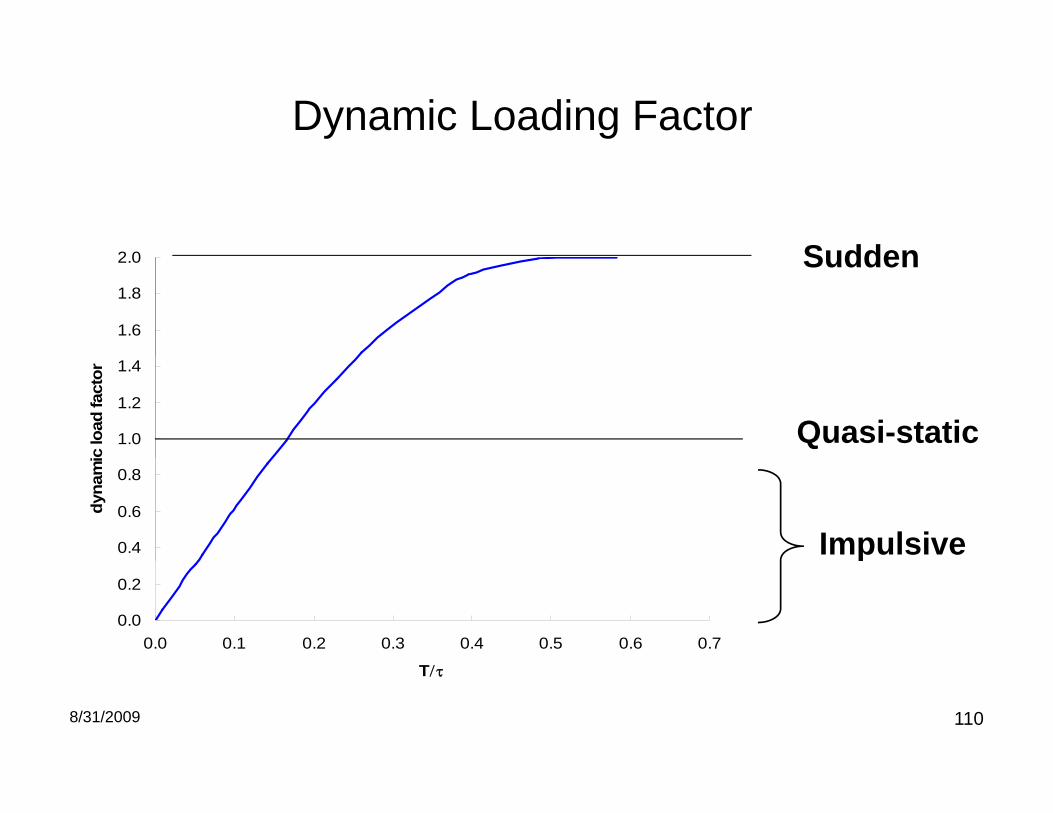
Dynamic Loading Factor
2 0 Sudden
1.6
1.8
2.0 Sudden
1.0
1.2
1.4
c lo
ad fa
ctor
Quasi-static
0.4
0.6
0.8
dyna
mi
Impulsive
0.0
0.2
0.0 0.1 0.2 0.3 0.4 0.5 0.6 0.7
p
8/31/2009 110
T

Effect of load localizationEffect of load localization
Infinite thin-walled (R/t>10) cylinder of radius R under uniform radial pressure p over length wlength w.
t
p
w
2R
t
8/31/2009 111

Load Length Factor
1.2
ent
0.8
1
disp
lace
me
0 4
0.6
d st
rain
or d
4/1
22
2 )1(3
hR
0
0.2
0.4
norm
aliz
ed 22
hR
00 2 4 6 8 10
w*
8/31/2009 112

BOC Methodology
• Estimate loading using SDOF model and account Yield stressg gfor finite length of load.
e d st ess
Yhoop wFTh
RPPP
max
0max, ThP 0
From explosion pressureestimate
Diameter and Schedule of pipe
Dynamic Load Factor Load length factor
8/31/2009 113
pipe

Hazard larger for bigger, thinner pipes
5
6Schedule 10Schedule 40Schedule 80
0.2% strain limit for reflected detonation pressure in H2-N2O
4
5
e (b
ar)
Schedule 160WT1WT2WT3
2-in schedule 40
3
tial p
ress
ure
.
1
2
Max
ini
0
1
0 10 20 30 40 50
10-in schedule 40
8/31/2009 114
0 10 20 30 40 50Radius/thickness

DetonationsDetonations
7 Sept 2009 Shepherd - Explosion Effects 115

Detonations are pressure wavesp
Austin & Shepherd 2003
7 Sept 2009 Shepherd - Explosion Effects 116

Detonation Followed by an Expansion Wavett
“Taylor-Zel’dovich” wave – similarity
nd
particle path
end
solution for constant detonation speed andIsentropic flow in perfect gas
osed
en
open
e
3
Stationary region
perfect gas.
clo
2
i f
Stationary region
Lx0 1 - at rest
expansion fan
7 Sept 2009 Shepherd - Explosion Effects 117detonation

Spatial distribution of PressureSpreads linearly with increasing time.
7 Sept 2009 Shepherd - Explosion Effects 118
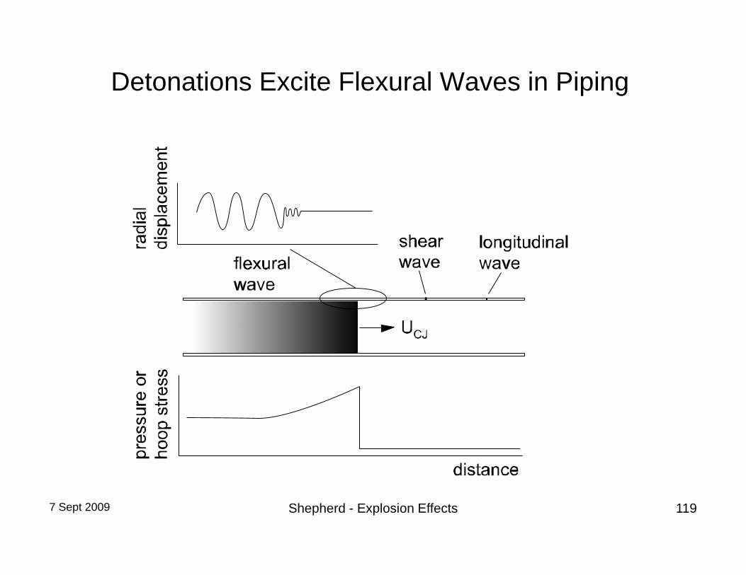
Detonations Excite Flexural Waves in Piping
7 Sept 2009 Shepherd - Explosion Effects 119

Measuring Elastic Vibration
Ch 2004
7 Sept 2009 Shepherd - Explosion Effects 120
Chao 2004

Flexural Wave Resonance in Tubes
Measured strain (hoop)
10-4
0 4 6 8
10
• Coupled response due to hoop oscillations and bending
t (ms)0 2 4 6 8
oscillations and bending• Traveling load can excite
resonance when flexural wave group velocity matches wave speed
Amplification factor
g y• Can be treated with analytical and
FEM models
B l d Sh h d 2002
7 Sept 2009 Shepherd - Explosion Effects 121
U (m/s)Beltman and Shepherd 2002

Detonation-Induced Failure of Piping Systems
• Initiation of cracks at flaws• Plastic deformation at• Plastic deformation at
– Location of transition from deflagration to detonation– Reflection from bends tees dead ends– Reflection from bends, tees, dead ends
• Rupture– Plastic instability to to prolonged application of highPlastic instability to to prolonged application of high
pressure• Bending pipes or support structuresg p p pp
– Forces created by detonation wave changing direction
7 Sept 2009 Shepherd - Explosion Effects 122

Detonation-Induced Fracture
Fracture
External Blast
Fracture
Chao 2004
7 Sept 2009 Shepherd - Explosion Effects 123

Outer diameter: 41 28 mm Wall thickness: 0 89 mm Length: 0 914 m
Fracture Behavior is a Strong Function of Initial Flaw Length
Post-test Al 6061-T6
Outer diameter: 41.28 mm, Wall thickness: 0.89 mm, Length: 0.914 mSurface notch dimensions: Width: 0.25 mm, Notch depth: 0.56 mmChao 2004
Post-test Al 6061-T6 Specimens (Pcj = 6.2 MPa)
Surface Notch Length = 1 27 cmSurface Notch Length = 1.27 cm
Surface Notch Length = 2 54 cmSurface Notch Length = 2.54 cm
Surface Notch Length = 5.08 cm
Surface Notch Length = 7.62 cm
7 Sept 2009 Shepherd - Explosion Effects 124Detonation wave direction

Special Issues in Piping Systems
• Two types of loads :– Short period hoop oscillation– Long period beam bending modes
• Significant in piping systems– Traveling load creates series of impulses at bends, tees and closed ends– Dynamic pressure must be accounted for in computing magnitude of impulse– Strains due to bending comparable or larger than hoop strains
7 Sept 2009 Shepherd - Explosion Effects 125

Piping System Response
Straight pipeStraight pipebend
8/31/2009 126tee closed end

Pressure Waves on 90o Bend
extrados intrados
Extrados compression waves higher pressure peaks
Intrados expansion waves lower pressure peaks
7 Sept 2009 Shepherd - Explosion Effects 127
higher pressure peaks lower pressure peaksLiang, Curran and Shepherd 2007

Transverse Flow Forces in a 90o Bend
dZ
~ dV ~F
Z~~ ˆdA
ZP ˆ dA
Momentum equation (general case):
dt
Zρ~u dV = −F −
Zρ~u~u · ndA−
ZPn dA
Simplification for uniform, steady flow:
~F = xA1¡P1 + ρ1u
21
¢+ yA2
¡P2 + ρ2u
22
¢General unsteady case:
~F = xFx(t) + yFy(t)
32 ~ PPu Dynamic pressure within Taylor wave 3
))((2)( PPtPAtF
y p y
Approximate transverse force
7 Sept 2009 Shepherd - Explosion Effects 128
Behind detonation front 33 ))((2)( PPtPAtF

8/31/2009 129

8 PCB pressure gages8 PCB pressure gages17 strain gages3 displacement gagesSpark ignition on W end1 MHz recording for 0.5 s
8/31/2009 130

8/31/2009 131

8/31/2009 132

8/31/2009 133

8/31/2009 134

350
300
= 1 Reflected CJ
200
250
150
stra
in
Shot 3
50
100shot 4shot 5Shot 6Shot 22
= 1 Propagating CJ
0
50
1 2 3 4 5 6 7 8 9 10 11 12 13 14 15 16 17
Shot 23CJCJ - Ref
8/31/2009 135
Gage number

DDT
• Deflagration to detonation transition is a common industrial hazard with gaseous explosionsindustrial hazard with gaseous explosions
• Compression of gas by flame increases pressure when detonation finally occurs “pressure piling”when detonation finally occurs pressure piling .
• Represents upper bound in severity of pressure loading.oad g
7 Sept 2009 Shepherd - Explosion Effects 136

Deflagration to Detonation Transition
burned unburned
1. A smooth flame with laminar flow ahead
• Flame creates flow– Pressure build-up
• Detonation onset
2. First wrinkling of flame and instability of upstream flow
Detonation onset– Localized
3. Breakdown into turbulent flow and a corrugated flame
4. Production of pressure waves ahead of turbulent flame
5. Local explosion of vortical structure within the flame
7 Sept 2009 Shepherd - Explosion Effects 1376. Transition to detonation

DDT Near End Flange
Pressure History Strain History
rain
)tr
ain
(mic
rost
S
•15% H2 in H2-N2O at 1 atm initial pressure•Thermal ignitionTab obstacles inside 5’ long tube
8/31/2009 138
•Tab obstacles inside 5’ long tube

8/31/2009 139

8/31/2009 140

Other DDT Testing• Thick walled vessels for elastic response• Thick walled vessels for elastic response• Thin-walled vessels for plastic response and failure• Use bars or tabs as “obstacles” to cause flame acceleration• Range of mixtures studied H2-N2O, H2-O2, CH4, C2H4, C3H8-O2• Measurement of strain and pressure
7 Sept 2009 Shepherd - Explosion Effects 141

DDT Near End Flange
(mic
rost
rain
)S
train
•15% H2 in H2-N2O at 1 atm initial pressure•Thermal ignition
7 Sept 2009 Shepherd - Explosion Effects 142
•Tab obstacles inside tube Liang, Karnesky & Shepherd 2006

H2-O2
CJ- ref
CJCV
Pintgen, Liang, & Shepherd 2007
7 Sept 2009 Shepherd - Explosion Effects 143
g , g, p

CH4-O2
Pintgen, Liang, & Shepherd 2007
7 Sept 2009 Shepherd - Explosion Effects 144
g , g, p

Conclusions of DDT Testing
• Peak pressures in DDT up to 10 X CJ-refWhit 1957 K k 1958 C d G i 1967 t– White 1957, Kogarko 1958, Craven and Grieg 1967, etc.
• Load is in impulsive regimeP k t i i bl t 2 5 t ti t i f• Peak strain is comparable to 2.5 x static strain of reflected detonationResults for four fuel oxygen systems comparable• Results for four fuel-oxygen systems comparable (H2, CH4, C2H4, C3H8)
7 Sept 2009 Shepherd - Explosion Effects 145

Water-Hammer Induced by DetonationDetonation
8/31/2009 146

Elementary Theory• Elastic tension• Elastic tension
precursor
• sound speed in water
• Flexural wave in tube l dcoupled to water
compression wave’’ t h ’’• ’’water hammer’’
(Al tube)
8/31/2009 147147147
Joukowsky 1898, von Karman 1911, Skalak 1956, Tijsseling 1996

8/31/2009 148

8/31/2009 149
8/31/2009 150
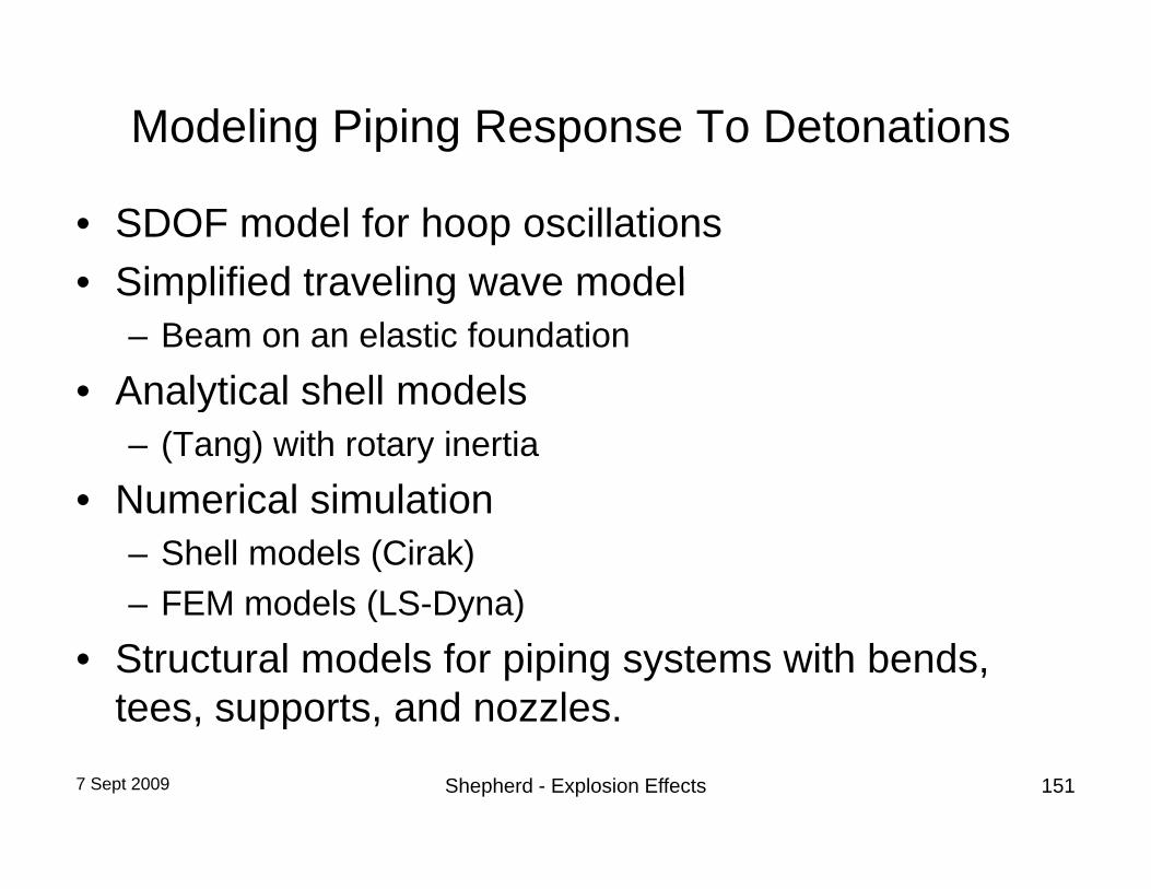
Modeling Piping Response To Detonations
• SDOF model for hoop oscillations• Simplified traveling wave model• Simplified traveling wave model
– Beam on an elastic foundation• Analytical shell models• Analytical shell models
– (Tang) with rotary inertia• Numerical simulation• Numerical simulation
– Shell models (Cirak)– FEM models (LS-Dyna)FEM models (LS Dyna)
• Structural models for piping systems with bends, tees, supports, and nozzles.
7 Sept 2009 Shepherd - Explosion Effects 151
, pp ,

Reference BooksReference Books
7 Sept 2009 Shepherd - Explosion Effects 152

References on Gaseous Explosions1. W. E. Baker, P. A. Cox, P. S.Westine, J. J. Kulesz, and R. A. Strehlow. Explosion
Hazards and Evaluation. Elsevier, 1983. This is the classic monograph with an extensive discussion of all aspects of explosion and structural response. It is i t d d t b d t il d t h i l f d id f i i l d iintended to be a detailed technical reference and guide for engineers involved in safety assessments. The book emphasizes hand calculation methods and is approximately evenly divided between the topics of characterizing explosion loading, and models of structural response. There are chapters on fragment and thermal effects and also a discussion on damage criteriathermal effects, and also a discussion on damage criteria.
2. Anon. Guidelines for Evaluating the Characteristics of Vapor Cloud Explosions, Flash Fires, and BLEVEs. AIChE, 1994. Center for Chemical Process Safety. This monograph is one of the series of publications by the Center for Chemical Processmonograph is one of the series of publications by the Center for Chemical Process Safety (CCPS) of the American Institute of Chemical Engineers http://www.aiche.org/ccps/. The emphasis is on pressure wave and thermal radiation from uncon¯ned vapor clouds and boiling liquid expanding vapor explosions (BLEVE). Oriented toward chemical process plant safety.
7 Sept 2009 Shepherd - Explosion Effects 153

References on Gaseous Explosions (cont)3. J. M. Kuchta. Investigation of ¯re and explosion accidents in chemical, mining, and fuel-
related industries - a manual. Bulletin 680, Bureau of Mines, 1985. The Bureau of Mines carried out an extensive research program on gaseous explosions and this publication summarizes much of the data on °ammability and explosion phenomena obtained by thissummarizes much of the data on ammability and explosion phenomena obtained by this group through the mid 1980s.
4. Dag Bjerketvedt, Jan Roar Bakke, and Kees van Wingerden. Gas explosion handbook. Journal Of Hazardous Materials, 52(1):1{150, January 1997. See the most recent online
i t htt // / Th t GEXCON AS h b ti lversion at http://www.gexcon.com/. The group at GEXCON AS has been very actively involved in explosion incident investigation and explosion protection studies. Their FLACS program is one of the most widely used tools for evaluating pressure wave generation by vapor cloud explosions in industrial facilities. This handbook (now online) provides a relatively easy to read introduction to all aspects of explosions with Chapter 8 providing an i t d ti t t t lintroduction to structural response.
5. K. Gugan. Unconfined Vapor Cloud Explosions. Gulf Publishing Company, 1978. Incidents of unconfined vapor cloud explosions from 1921 through 1979 are reviewed and detailed observations of structural damage are given for selected cases Analysis is now dated butobservations of structural damage are given for selected cases. Analysis is now dated but the factual material is very useful.
7 Sept 2009 Shepherd - Explosion Effects 154

References on Blast Waves1. S. Glasstone and P. J. Dolan. The Effects of Nuclear Weapons. United States Department of
Defense and Department of Energy, 3rd edition, 1977. As title indicates, the focus is on nuclear weapons. Air blasts are a significant aspect of nuclear weapons effects and provided the motivation for the large body of work carried out on blast waves during the cold war erathe motivation for the large body of work carried out on blast waves during the cold war era. Glasstone provides a detailed description of blast wave phenomena and the effect of nuclear blasts on structures.
2. W. E. Baker. Explosions in Air. University of Texas Press, Austin, Texas, 1973. Substantially overlaps material in Engineering Design Handbook. Explosions in Air. Volume 1. US Army Materiel Command 1974 AMCP 706 181 This is the classic monograph on blast waves andMateriel Command, 1974. AMCP 706-181. This is the classic monograph on blast waves and is more oriented to conventional high explosives than Glasstone.
3. G. F. Kinney and K. J. Graham. Explosive Shocks in Air. 2nd Ed. Springer, 1985. Covers similar topics as both Baker and Glasstone but more oriented to classroom study. Some limited discussion of structural effects.
4. Anon. Estimating air blast characteristics for single point explosions in air, with a guide to evaluation of atmospheric propagation and effects. Technical Report ANSI S2.20-1983 (ASA20-1983), American National Standards Institute, 1983. Discusses standardized approach for scaling air blasts from an ideal (point) explosion. Discusses long range propagation in the atmosphere and effect of various weather features. Some discussion about p p g pstructural effects such as window breakage.
7 Sept 2009 Shepherd - Explosion Effects 155

References on Structural Response1. W. E. Baker, P. A. Cox, P. S. Westine, J. J. Kulesz, and R. A. Strehlow. Explosion Hazards and Evaluation.
Elsevier, 1983. This is probably still the best single reference on analytical methods of structural response to explosion.
2 P D S ith d J G H th i t Bl t d B lli ti L di f St t B tt th/H i 19942. P.D. Smith and J.G. Hetherington. Blast and Ballistic Loading of Structures. Butter-worth/Heinemann, 1994. An alternative to Baker et al., covers much of same material, much less detail so that it is easier to grasp the concepts.
3. M. Paz and W. Leigh. Structural Dynamics. Springer, ¯fth edition, 2004. Modern all-around text on structural g y p g , ,response, oriented to civil engineers that are interested in earthquake response of structures. Integrates use of computer simulation (SAP2000) intothe text.
4. J. Biggs. Introduction to structural dynamics. McGraw-Hill, Inc., 1964. ISBN 07-005255-7. This is the classic t tb k i l d f f d d litextbook on single degree of freedom modeling.
5. N. Jones. Structural Impact. Cambridge University Press, 1989. ISBN 0-521-30180-7. Jones has a detailed discussion of plastic deformation which applications to both impact and impulsive pressure loading.
6. Anon. Structures to Resist the Effects of Accident Explosions. Departments of the Army, the Navy, and the p p y, y,Air Force, 1990. Design guide for concrete-reinforced structures. Very comprehensive but oriented to military installations.
7 Sept 2009 Shepherd - Explosion Effects 156

References on Mechanics1. M. F. Ashby and D. R. H. Jones. Engineering Materials I. Butterworth Heinemann, second
edition, 1996. Elementary discussion of the material properties relevant to mechanics with formulas and data that are useful for order of magnitude computations.
2. W. Nash. Strength of Materials. Schaum's Outlines, McGraw Hill, fourth edition, 1998. A2. W. Nash. Strength of Materials. Schaum s Outlines, McGraw Hill, fourth edition, 1998. A tutorial approach to the theory of the strength of materials that concentrations on beams.
3. A.C. Ugural and S.K. Fenster. Advanced Strength and Applied Elasticity. Elsevier, 2nd SI edition, 1987. An all-around text of elasticity, plasticity and applications to static problems in the strength of materials.
4 S P Timoshenko and J N Goodier Theor of Elasticit McGra HIll P blishing Compan4. S.P. Timoshenko and J. N. Goodier. Theory of Elasticity. McGraw-HIll Publishing Company, third edition, 1970. This is the classic text on elasticity. Emphasizes analytical solutions.
5. N. Noda, R.B. Hetnarski, and Y. Tanigawa. Thermal Stresses. Taylor and Francis, 2002. ISBN 1-56032-971-8. If you need to solve a problem that involves thermal stresses, this is the book to go to.
6. D. Broek. Elementary Engineering Fracture Mechanics. Kluwer Academic Publishers, fourth revised edition, 1991. Fracture mechanics is a key part of the modern approach to designing pressure vessels and piping.
7. W. Johnson and P. B. Mellor. Engineering Plasticity. Ellis Horwood Limited, 1983.8 C R Callidine Plasticity for Engineers Horwood Publishing Limited 20008. C. R. Callidine. Plasticity for Engineers. Horwood Publishing Limited, 2000.
7 Sept 2009 Shepherd - Explosion Effects 157

Handbooks1. W. Young and R. Budynas. Roark's formulas for stress and strain. McGraw-Hill, 2002. ISBN
0-07-072542-X. Seventh Edition. Roarks is an essential compendium of solutions for static problems in elasticity. Formulas for stress and strain for many shapes, boundary conditions, and loading problems are tabulatedand loading problems are tabulated.
2. R. D. Blevins. Formulas for natural frequency and mode shape. van Nostrand Reinhold Company, 1979. Blevins compilation is similar in philosophy to Roark’s but focuses on dynamic solutions, speci¯cally elastic vibrations of structures. He tabulates mode shapes and ib ti l f i f t t l l t d b d ditivibrational frequencies for many structural elements and boundary conditions.
3. A. S. Kobayashi, editor. Handbook on Experimental Mechanics. Society of Experimental Mechanics, second revised edition, 1993. If you have to perform or interpret experiments, Kobayashi's handbook is an excellent guide to various experimental methodsKobayashi s handbook is an excellent guide to various experimental methods.
4. J.R. Davis. Carbon and Alloy Steels. ASM international, 1996. ISBN 0-87170-557-5. Data on the most common construction material for piping and pressure vessels.
5. C. Moosbrugger. Atlas of stress-strain curves. Materials Park, OH : ASM international, 2002. Measured stress-strain curves for a wide range of materials.
7 Sept 2009 Shepherd - Explosion Effects 158

Books on Related Subjects are Useful• Earthquake engineering
– Strong ground motion excites building motion• Terminal ballistics
– Projectile impact creates stress waves and vibration• Crashworthiness
– Vehicle crash mitigation • Weapons effects
– Conventional (High explosive and FAE)– Nuclear and nuclear simulation testing
TIP – Many recent studies on structural response to blasts have been sponsored to counter terrorism – the results are often restricted to
7 Sept 2009 Shepherd - Explosion Effects 159
government agencies or official use only.

Web Resources
• For more resources, preprints, and reports from Caltech Explosion Dynamics Lab seeCaltech Explosion Dynamics Lab, see
http://www.galcit.caltech.edu/EDL
7 Sept 2009 Shepherd - Explosion Effects 160