express single-carrier das - amazon web services · express single-carrier das installation and...
TRANSCRIPT

Version 2.2 – November 2013 ©2013 SOLiD. All Rights Reserved. Confidential & Proprietary. www.solid.com
EXPRESS Single-Carrier DAS Installation and Operations Manual

EXPRESS DAS Installation and Operations Manual
Version 2.2 – November 2013 ©2013 SOLiD. All Rights Reserved. Confidential & Proprietary. www.solid.com
Revision Log
Revision # Issue Date Section Changes
V 1.0 April 11, 2011 All Initial Release
V 1.0 June 1, 2012 All Added Sprint band
V 2.0 May 16, 2013 All Revisions and updates to all sections
V 2.1 June 10, 2013 DMS Updates to DMS-600 Information
V 2.2 November 22, 2013 Sections 8-12 Updates to installation and commissioning
Copyright
This manual is written and produced by SOLiD and printed in the USA. All rights are reserved ©2013
SOLiD. Confidential and proprietary. Information contained in this document is company private to SOLiD
and should not be modified, used, copied, reproduced or disclosed in whole or in part without the written
consent of SOLiD.
Trademark Information
No right, license, or interest to SOLiD trademarks is granted here. By using this document, you agree not
to assert any right, license, or interest with respect to such trademark. Other product names mentioned in
this manual are used for identification purposes only and may be trademarks or registered trademarks of
their respective companies.
Disclaimer of Liability
The contents of this document, including graphics and screenshots, are current as of the date of
publication. SOLiD reserves the right to change the contents without prior notice. In no event shall SOLiD
be liable for any damages resulting from loss of data, loss of use or loss of profits. SOLiD further
disclaims any and all liability for indirect, incidental, special, consequential or other similar damages. This
disclaimer of liability applies to all products, publications and services during and after the warranty period.
EXPRESS DAS Installation and Operations Manual
EXPRESS DAS Installation and Operations Manual – Version 2.2 November 2013 i
Contents
1 Introduction ............................................................................................................... 1 1.1 Intended Audience ....................................................................................................................... 1 1.2 Document Conventions ................................................................................................................ 1 1.3 Getting Support ............................................................................................................................ 1 1.4 Safety and EMC Approvals .......................................................................................................... 2 1.5 Safety Precautions ....................................................................................................................... 2
2 Overview and Specifications ................................................................................... 3 2.1 Features ....................................................................................................................................... 4 2.2 System Components .................................................................................................................... 4 2.3 SISO Configuration ...................................................................................................................... 6 2.4 MIMO Configuration ..................................................................................................................... 7 2.5 VHF/UHF Support ........................................................................................................................ 7 2.6 System Capacities ....................................................................................................................... 8 2.7 Mechanical Specifications ............................................................................................................ 9 2.8 Environmental Specifications ..................................................................................................... 10 2.9 Optic Specifications ................................................................................................................... 11 2.10 Frequency Bands ...................................................................................................................... 11 2.11 Band Specifications ................................................................................................................... 12
2.11.1 Output Power Level ...................................................................................................... 12 2.11.2 RF Specifications .......................................................................................................... 12
3 BTS Interface Unit (BIU) ......................................................................................... 13 3.1 BIU Specifications ...................................................................................................................... 14
3.1.1 BIU Mechanical Specifications ...................................................................................... 15 3.1.2 BIU Environmental Data ................................................................................................ 15
3.2 BIU Components ........................................................................................................................ 16 3.2.1 Main Drive BTS Unit (MDBU) ........................................................................................ 18 3.2.2 Main Combiner Divider Unit (MCDU) ............................................................................ 20 3.2.3 Main Central Processor Unit (MCPU) ........................................................................... 21 3.2.4 Main Power Supply Unit (MPSU) .................................................................................. 22
3.3 BIU Front / Rear Panel – Indicators and Connectors ................................................................. 23 3.4 EXPRESS DC Power Supply (SC-RMP-480) ............................................................................ 25
3.4.1 SC-RMP-480 Features .................................................................................................. 25 3.4.2 SC-RMP-480 Specifications .......................................................................................... 25
4 Optical Distribution Unit (ODU) ............................................................................. 26 4.1 ODU Specifications .................................................................................................................... 27
4.1.1 ODU Mechanical Specifications .................................................................................... 28 4.1.2 ODU Environmental Data .............................................................................................. 28
4.2 ODU Components ...................................................................................................................... 29 4.2.1 Donor Optic Unit (DOU) ................................................................................................ 30
4.3 Donor Optic Unit Specifications ................................................................................................. 31 4.3.1 Optical Data ................................................................................................................... 31 4.3.2 Electrical Data ............................................................................................................... 31
4.4 ODU Front / Rear Panel – Indicators and Connectors ............................................................... 32
5 Remote Units – MRU, ARU, VHF/UHF AOR .......................................................... 33 5.1 MRU/ARU Specifications ........................................................................................................... 34
5.1.1 MRU/ARU Mechanical Specifications ........................................................................... 35
EXPRESS DAS Installation and Operations Manual
ii EXPRESS DAS Installation and Operations Manual – Version 2.2 November 2013
5.1.2 MRU/ARU Environmental Data ..................................................................................... 35 5.1.3 MRU/ARU Mechanical Specifications ........................................................................... 36 5.1.4 MRU RF Specifications ................................................................................................. 37 5.1.5 ARU RF Specifications .................................................................................................. 38
5.2 MRU/ARU Components ............................................................................................................. 39 5.2.1 Main RF Module/Add-on RF Module (MRFM/ARFM) and Band Pass Filters ............... 40 5.2.2 Remote Power Supply Unit (RPSU) .............................................................................. 40 5.2.3 Remote Optic (R-OPT) .................................................................................................. 41 5.2.4 Remote Central Processor Unit (RCPU) ....................................................................... 41
5.3 MRU/ARU Connectors (Top / Bottom Views) ............................................................................ 42 5.3.1 MRU/ARU Top View ...................................................................................................... 42 5.3.2 MRU/ARU Bottom View and Connectors ...................................................................... 43
5.4 MRU / ARU Power Ports ............................................................................................................ 44 5.5 VHF/UHF AOR Specifications ................................................................................................... 45
5.5.1 Band Specifications 150MHz VHF Public Safety .......................................................... 46 5.5.2 Band Specifications 450MHz UHF Public Safety .......................................................... 46
5.6 VHF/UHF AOR Components ..................................................................................................... 47 5.6.1 AOR Remote Drive Unit (RDU) ..................................................................................... 47 5.6.2 AOR Power Supply Unit (PSU) ..................................................................................... 48 5.6.3 AOR System Interface Unit (SIU) .................................................................................. 48
5.7 VHF/UHF AOR Rear View Connectors ...................................................................................... 48 5.8 VHF/UHF AOR Power Ports and External Ports ....................................................................... 49
6 Optic Expansion Unit (OEU) .................................................................................. 50 6.1 OEU Specifications .................................................................................................................... 51
6.1.1 OEU Environmental Data .............................................................................................. 51 6.1.2 OEU Mechanical Specifications .................................................................................... 52
6.2 OEU Components ...................................................................................................................... 53 6.2.1 OEU Components – Mechanical Specifications ............................................................ 54 6.2.2 Donor Optic Unit ............................................................................................................ 55 6.2.3 Extension Wavelength Division Multiplexer (EWDM) .................................................... 55 6.2.4 Expansion Central Processor Unit (ECPU) ................................................................... 55 6.2.5 Expansion Radio Frequency Module (ERFM) ............................................................... 55 6.2.6 Expansion Power Supply Unit (EPSU) .......................................................................... 55
6.3 OEU Front / Rear Panel – Indicators and Connectors ............................................................... 56
7 DAS Management System (DMS-600) ................................................................... 57 7.1 DMS-600 Specifications ............................................................................................................. 58 7.2 DMS-600 Front / Rear Panel – Indicators and Connectors ....................................................... 59
8 Installation – Headend Equipment: BIU, Power Supply, ODU, DMS-600 ........... 60 8.1 Before you Begin ....................................................................................................................... 60 8.2 Install BIU Chassis ..................................................................................................................... 62 8.3 Install DC Power Shelf and Connect to BIU ............................................................................... 62
8.3.1 BIU Power Consumption ............................................................................................... 64 8.3.2 Installing Additional MDBUs .......................................................................................... 65
8.4 Connect BIU to the RF Source – BTS or BDA ........................................................................... 66 8.4.1 Connecting the BIU to a BTS ........................................................................................ 68 8.4.2 Connecting the BIU with BDA ....................................................................................... 69 8.4.3 Checking Power and RF Signaling ................................................................................ 70
8.5 Install Optical Drive Units (ODUs) .............................................................................................. 71 8.6 Connect ODU to BIU for Power and Signaling .......................................................................... 72
8.6.1 ODU Power Consumption ............................................................................................. 74 8.6.2 Installing DOUs ............................................................................................................. 74

EXPRESS DAS Installation and Operations Manual
EXPRESS DAS Installation and Operations Manual – Version 2.2 November 2013 iii
8.6.3 Connecting ODU Optic Cabling ..................................................................................... 75 8.7 Installing the DMS-600 ............................................................................................................... 75
9 Installation – OEU ................................................................................................... 76 9.1 Before you Begin ....................................................................................................................... 76 9.2 Install OEU Chassis ................................................................................................................... 77 9.3 Install DC Power Shelf and Connect to OEU ............................................................................. 77
9.3.1 OEU Power Consumption ............................................................................................. 78 9.3.2 Installing DOUs ............................................................................................................. 78
9.4 Connecting the OEU to ODU(s) ................................................................................................. 79
10 Installation – MRU and ARU ................................................................................... 80 10.1 Before you Begin ....................................................................................................................... 80 10.2 Install MRU/ARU Enclosures – Wall Mount ............................................................................... 81
10.2.1 MRU/ARU Wall Mount – Side-by-Side Installation ....................................................... 81 10.2.2 MRU/ARU Wall Mount – Stacked Installation ............................................................... 83 10.2.3 MRU/ARU Rack Mount – Vertical Installation .............................................................. 85 10.2.4 MRU/ARU Rack Mount – Horizontal Installation .......................................................... 87
10.3 Connect MRU / ARU Power ...................................................................................................... 88 10.3.1 MRU/ARU Power Consumption .................................................................................... 89
10.4 Connect Ground Terminal ......................................................................................................... 90 10.5 Connect Optical Cabling ............................................................................................................ 91 10.6 Connect MRU and ARU ............................................................................................................ 92 10.7 Connect Coaxial Cable and Antenna ........................................................................................ 93 10.8 Power On MRU / ARU and Check Status ................................................................................. 94
11 Installation – VHF/UHF Add-on Remote ................................................................ 95 11.1 Before you Begin ....................................................................................................................... 95 11.2 Installing the VHF/UHF AOR – Wall Mount ............................................................................... 96 11.3 Installing the VHF/UHF AOR – Rack Mounting ......................................................................... 98 11.4 Installing Power Cabling ............................................................................................................ 98
11.4.1 VHF/UHF AOR Power Consumption ............................................................................ 99 11.5 Connecting Ground (GND) Terminal ......................................................................................... 99 11.6 Connecting the Add-on Unit to the MRU ................................................................................. 100 11.7 Connecting Coaxial Cable and Antennas ................................................................................ 101 11.8 Powering On Add-on Unit and Checking Status ...................................................................... 101
12 System Commissioning ....................................................................................... 102 12.1 Before you Begin ..................................................................................................................... 102 12.2 Connect DMS-600 to EXPRESS DAS ..................................................................................... 103 12.3 Open Management Software and Run EasySET .................................................................... 104 12.4 Changing Factory Defaults ...................................................................................................... 105 12.5 Manual Setup .......................................................................................................................... 107
12.5.1 Load the Command & Control Menu .......................................................................... 107 12.5.2 Verify all Connections ................................................................................................. 108 12.5.3 Set MDBU Parameters ............................................................................................... 108 12.5.4 Set Optic Compensation ............................................................................................. 109 12.5.5 Set MRU/ARU Parameters ......................................................................................... 111
12.6 System Acceptance ................................................................................................................. 112 12.6.1 Validating the Uplink Path .......................................................................................... 113 12.6.2 Validating the Downlink Path ...................................................................................... 114
12.7 Alarm Troubleshooting ............................................................................................................ 115 12.7.1 ODU Alarm Troubleshooting ....................................................................................... 115 12.7.2 BIU Alarm Troubleshooting ......................................................................................... 116

EXPRESS DAS Installation and Operations Manual
iv EXPRESS DAS Installation and Operations Manual – Version 2.2 November 2013
12.7.3 MRU Alarm Troubleshooting ...................................................................................... 117 12.7.4 OEU Alarm Troubleshooting ....................................................................................... 118
13 Appendix – Additional Functions ........................................................................ 119 13.1 Shutdown Function (Tx Output Shutdown) .............................................................................. 119 13.2 Total Power Limit Function (Tx Output ALC) ........................................................................... 119 13.3 Automatic Output Power Setting Function (Tx Output AGC) ................................................... 120 13.4 Input Power AGC Function (Tx Input AGC) ............................................................................. 120 13.5 Input Power Limit Function (Tx Input ALC) .............................................................................. 121 13.6 Optic Loss Compensation ....................................................................................................... 121
14 Appendix – EXPRESS Part Numbers .................................................................. 122
15 Appendix – Glossary of Terms ............................................................................ 125
List of Illustrations Figure 2.1 – EXPRESS Distributed Antenna System (DAS) Topology ....................................................... 5 Figure 2.2 – EXPRESS DAS – SISO Configuration .................................................................................... 6 Figure 2.3 – EXPRESS DAS – MIMO Configuration ................................................................................... 7 Figure 2.4 – EXPRESS DAS – VHF/UHF Configuration ............................................................................. 7 Figure 3.1 – BIU Block Diagram ................................................................................................................ 13 Figure 3.2 – BIU Dimensions ..................................................................................................................... 14 Figure 3.3 – BIU Components ................................................................................................................... 16 Figure 3.4 – MDBU at a glance ................................................................................................................. 18 Figure 3.5 – MCDU at a Glance ................................................................................................................ 20 Figure 3.6 – MCPU at a Glance ................................................................................................................. 21 Figure 3.7 – MPSU at a Glance ................................................................................................................. 22 Figure 3.8 – BIU Front Panel ..................................................................................................................... 23 Figure 3.9 – BIU Rear Panel ...................................................................................................................... 24 Figure 3.10 – DC Power Supply Front View .............................................................................................. 25 Figure 4.1 – ODU Block Diagram .............................................................................................................. 26 Figure 4.2 – ODU Dimensions ................................................................................................................... 27 Figure 4.3 – DOU at a Glance ................................................................................................................... 30 Figure 4.4 – ODU Front Panel ................................................................................................................... 32 Figure 4.5 – ODU Rear Panel .................................................................................................................... 32 Figure 5.1 – MRU/ARU Block Diagram ...................................................................................................... 33 Figure 5.2 – MRU/ARU Dimensions .......................................................................................................... 34 Figure 5.3 – MRU 850C+1900P Internal View ........................................................................................... 39 Figure 5.4 – MRU / ARU Top Connectors ................................................................................................. 42 Figure 5.5 – MRU / ARU Bottom Connectors ............................................................................................ 43 Figure 5.6 – MRU / ARU Power Connectors ............................................................................................. 44 Figure 5.7 – VHF/UHF AOR at a Glance ................................................................................................... 45 Figure 5.8 – VHF/UHF AOR Internal View ................................................................................................ 47 Figure 5.9 – VHF/UHF AOR Rear View Connectors ................................................................................. 48 Figure 5.10 – AOR Power Port .................................................................................................................. 49 Figure 5.11 – AOR External Port ............................................................................................................... 49 Figure 6.1 – OEU Block Diagram ............................................................................................................... 50 Figure 6.2 – OEU Dimensions ................................................................................................................... 51

EXPRESS DAS Installation and Operations Manual
EXPRESS DAS Installation and Operations Manual – Version 2.2 November 2013 v
Figure 6.3 – OEU Internal View ................................................................................................................. 53 Figure 6.4 – OEU Front Panel ................................................................................................................... 56 Figure 6.5 – OEU Rear Panel .................................................................................................................... 56 Figure 7.1 – DAS Management with DMS-600 .......................................................................................... 57 Figure 7.2 – DMS-600 at a Glance ............................................................................................................ 58 Figure 7.3 – DMS-600 Front Panel ............................................................................................................ 59 Figure 7.4 – DMS-600 Rear Panel ............................................................................................................. 59 Figure 8.1 – BIU Rack Installation ............................................................................................................. 62 Figure 8.2 – BIU Terminal Block ................................................................................................................ 63 Figure 8.3 – MPSU LED Indicators ............................................................................................................ 63 Figure 8.4 – MDBU Installation .................................................................................................................. 65 Figure 8.5 – BIU RF interface diagram ...................................................................................................... 67 Figure 8.6 – BTS Interface to the BIU Backplane ...................................................................................... 68 Figure 8.7 – BDA Interface to the BIU Backplane Using a Duplexer ......................................................... 69 Figure 8.8 – MDBU LED Indicators and SMA Test Ports .......................................................................... 70 Figure 8.9 – ODU Rack Installation ........................................................................................................... 71 Figure 8.10 – BIU RF and Signaling Ports ................................................................................................. 72 Figure 8.11 – Connecting the BIU to ODU(s) ............................................................................................ 73 Figure 8.12 – ODU Showing One and Two DOU Configurations .............................................................. 74 Figure 8.13 – SC/APC Fiber Terminations ................................................................................................ 75 Figure 9.1 – OEU Terminal Block .............................................................................................................. 77 Figure 9.2 – OEU Showing One and Two DOU Configurations ................................................................ 78 Figure 9.3 – Connecting the OEU to ODU ................................................................................................. 79 Figure 10.1 –MRU and ARU Dimensions .................................................................................................... 81 Figure 10.2 – Side-by-Side Wall Mount Installation for the MRU / ARU .................................................... 82 Figure 10.3 – Dimensions of Stacking Bracket .......................................................................................... 83 Figure 10.4 – Stack Mounting the MRU/ARU ............................................................................................ 84 Figure 10.5 – Dimensions for MRU/ARU Vertical Rack Installation ........................................................... 85 Figure 10.6 – MRU/ARU Installation Procedure for Vertical Rack ............................................................. 86 Figure 10.7 – Dimensions for MRU/ARU Horizontal Rack Installation ...................................................... 87 Figure 10.8 – MRU/ARU Installation Procedure for Horizontal Rack ......................................................... 88 Figure 10.9 – MRU / ARU Power Ports – AC/DC and DC/DC ................................................................... 88 Figure 10.10 – MRU / ARU Ground Terminal ............................................................................................ 90 Figure 10.11 – Attaching Fiber Optic Cabling to the MRU ......................................................................... 91 Figure 10.12 – Connecting the MRU to the ARU ....................................................................................... 92 Figure 11.1 – Recommended Clearances for VHF/UHF AOR Wall Mounting ........................................... 96 Figure 11.2 – VHF/UHF AOR Wall Mount Dimensions ............................................................................. 97 Figure 11.3 – Wall Mounting the AOR ....................................................................................................... 97 Figure 11.4 – VHF/UHF AOR Power Port ................................................................................................. 98 Figure 11.5 – VHF/UHF AOR Ground Port ................................................................................................ 99 Figure 11.6 – Connecting the MRU to VHF/UHF AOR ............................................................................ 100 Figure 11.7 – Power and Alarm Indicators for AOR ................................................................................ 101 Figure 12.1 – Connecting Laptop to DMS-600 ........................................................................................ 103 Figure 12.2 – Management Software Home Screen ............................................................................... 104 Figure 12.3 – EasySET Progress Bar ...................................................................................................... 105 Figure 12.4 – System Setup Screen ........................................................................................................ 106 Figure 12.5 – Command & Control Screen .............................................................................................. 107 Figure 12.6 – Setting MDBU Parameters ................................................................................................ 108 Figure 12.7 – Setting Optic Values .......................................................................................................... 109

EXPRESS DAS Installation and Operations Manual
vi EXPRESS DAS Installation and Operations Manual – Version 2.2 November 2013
Figure 12.8 – Configuration Screen ......................................................................................................... 111 Figure 12.9 – Validating the Uplink Path ................................................................................................. 113 Figure 12.10 – Validating the Downlink Path ........................................................................................... 114 Figure 13.1 – Optical Loss Information .................................................................................................... 121
List of Tables Table 2.1 – Mechanical Specifications for BIU, ODU, OEU ........................................................................ 9 Table 2.2 – Mechanical Specifications for MRU, ARU, VHF/UHF AOR .................................................... 10 Table 2.3 – Environmental Specifications .................................................................................................. 10 Table 2.4 – Optic Wavelength and Laser Power ....................................................................................... 11 Table 2.5 – Frequency Bands .................................................................................................................... 11 Table 2.6 – Output Power Level By Band .................................................................................................. 12 Table 2.7 – RF Specifications .................................................................................................................... 12 Table 3.1 – BIU Mechanical Specifications ............................................................................................... 15 Table 3.2 – BIU Environmental Data ......................................................................................................... 15 Table 3.3 – BIU Components and Functions ............................................................................................. 16 Table 3.4 – BIU Components -- Power Consumption, Weight and Dimension ......................................... 17 Table 3.5 – MDBU Supported Bands and Frequencies ............................................................................. 19 Table 3.6 – MCDU – VHF/UHF Frequency Band ...................................................................................... 20 Table 3.7 – BIU Front Panel Indicators ...................................................................................................... 23 Table 3.8 – BIU Rear Panel Connectors .................................................................................................... 24 Table 3.9 – DC Power Supply Specifications ............................................................................................ 25 Table 4.1 – ODU Mechanical Specifications ............................................................................................. 28 Table 4.2 – ODU Environmental Data ....................................................................................................... 28 Table 4.3 – ODU Components ................................................................................................................... 29 Table 4.4 – ODU Components – Mechanical Specifications ..................................................................... 29 Table 4.5 – DOU Optical Data ................................................................................................................... 31 Table 4.6 – DOU Electrical Data ................................................................................................................ 31 Table 4.7 – ODU Front Panel Indicators .................................................................................................... 32 Table 4.8 – ODU Rear Panel Connectors .................................................................................................. 32 Table 5.1 – MRU/ARU Mechanical Specifications ..................................................................................... 35 Table 5.2 – MRU/ARU Environmental Data ............................................................................................... 35 Table 5.3 – MRU/ARU Mechanical Specifications ..................................................................................... 36 Table 5.4 – MRU RF Specifications ........................................................................................................... 37 Table 5.5 – ARU RF Specifications ........................................................................................................... 38 Table 5.6 – MRU / ARU Components ........................................................................................................ 39 Table 5.7 – Main RF Module/Add-on RF Module (MRFM/ARFM) and Band Pass Filters ......................... 40 Table 5.8 – Remote Power Supply Unit – Range of Input Power .............................................................. 40 Table 5.9 – MRU / ARU Top Connectors ................................................................................................... 42 Table 5.10 – MRU / ARU Bottom Connectors ........................................................................................... 43 Table 5.11 – VHF/UHF AOR Mechanical Specifications ........................................................................... 45 Table 5.12 – Band Specifications 150MHz VHF Public Safety .................................................................. 46 Table 5.13 – Band Specifications 450MHz UHF Public Safety ................................................................. 46 Table 5.14 – VHF/UHF AOR Components ................................................................................................ 47 Table 5.15 – VHF/UHF AOR Connectors .................................................................................................. 48 Table 6.1 – OEU Environmental Data ........................................................................................................ 51 Table 6.2 – OEU Mechanical Specifications .............................................................................................. 52 Table 6.3 – OEU Components ................................................................................................................... 54

EXPRESS DAS Installation and Operations Manual
EXPRESS DAS Installation and Operations Manual – Version 2.2 November 2013 vii
Table 6.4 – OEU Components – Mechanical Specifications ..................................................................... 54 Table 6.5 – OEU Front Panel Indicators .................................................................................................... 56 Table 6.6 – OEU Rear Panel Connectors .................................................................................................. 56 Table 7.1 – DMS-600 Specifications .......................................................................................................... 58 Table 7.2 – DMS-600 Front Panel Indicators ............................................................................................. 59 Table 7.3 – DMS-600 Rear Panel Connectors .......................................................................................... 59 Table 8.1 – Tools and Accessories for Installing Headend Equipment ...................................................... 61 Table 8.2 – BIU Power Consumption ......................................................................................................... 64 Table 8.3 – Port Assignments for Connecting Input and Output to RF Source ......................................... 66 Table 8.4 – ODU Power Consumption ....................................................................................................... 74 Table 9.1 – Accessories and Tools List for OEU Installation ..................................................................... 76 Table 9.2 – OEU Power Consumption ....................................................................................................... 78 Table 10.1 – Tools and Accessories for Installing MRUs/ARUs ................................................................ 80 Table 10.2 – MRU/ARU Power Consumption ............................................................................................ 89 Table 10.3 – MRU/ARU Cable Connections .............................................................................................. 93 Table 10.4 – MRU LED Indicators ............................................................................................................. 94 Table 11.1 – Tools and Accessories for Installing VHF/UHF Add-on Remote ........................................... 95 Table 11.2 – VHF/UHF AOR Power Connections ..................................................................................... 98 Table 11.3 – VHF/UHF AOR Power Consumption .................................................................................... 99 Table 11.4 – VHF/UHF AOR / MRU Connections ................................................................................... 100 Table 12.1 – Tools and Accessories for System Commissioning ............................................................ 102 Table 12.2 – Optic Compensation ........................................................................................................... 110 Table 12.3 – Recommended Test and Link Budget Values Per Band for Uplink Path ............................ 113 Table 12.4 – Recommended Test and Link Budget Values Per Band for Downlink Path ....................... 114 Table 12.5 – Alarm Indicators in Management Software ......................................................................... 115 Table 12.6 – ODU Alarm Indicators in Management Software ................................................................ 115 Table 12.7 – BIU Alarm Indicators in Management Software .................................................................. 116 Table 12.8 – MRU Alarm Indicators in Management Software ................................................................ 117 Table 12.9 – OEU Alarm Indicators in Management Software ................................................................ 118 Table 13.1 – Attenuation (ATT) Level Values .......................................................................................... 120 Table 14.1 – BIU Part Numbers ............................................................................................................... 122 Table 14.2 – ODU/OEU Part Numbers .................................................................................................... 122 Table 14.3 – MRU and ARU Part Numbers ............................................................................................. 123 Table 14.4 – DMS-600 Part Numbers ..................................................................................................... 123 Table 14.5 – Link Balancer Unit Part Numbers ....................................................................................... 124


EXPRESS DAS Installation and Operations Manual
EXPRESS DAS Installation and Operations Manual – Version 2.2 November 2013 1
1 Introduction 1.1 Intended Audience The EXPRESS DAS user documentation is intended for technicians responsible for planning,
administering, configuring and maintaining the EXPRESS Single-Carrier Distributed Antenna System
(DAS). Technicians using the manual should already have completed the EXPRESS Single-Carrier DAS
online training course offered through SOLiD University.
SOLiD recommends technicians be familiar with the concepts of fiber optic cabling, networking and
wireless communication technologies, and SNMP. We further recommend training programs offered
through CIBET (Certified In Building Engineering Technologist) and BICSI (Building Industry Consulting
Service International).
1.2 Document Conventions
The Caution icon indicates conditions or procedures that could cause personal injury or interrupt the operation of the system.
1.3 Getting Support To authorize technical support or to establish a return authorization for defective units, make sure you
have the SOLiD serial numbers available. Serial numbers are located on the back of the unit, as well as
on the box in which it was delivered. You can get additional support information by contacting SOLiD by
email or telephone: [email protected] 1-888-409-9997, Option #2
SOLiD welcomes feedback on this manual. Please send suggestions to [email protected] with the term
“Tech Pubs” in the subject line.
NOTE: A NOTE indicates important “heads-up” information that will assist with the installation and
commissioning process.

EXPRESS DAS Installation and Operations Manual
2 EXPRESS DAS Installation and Operations Manual – Version 2.2 November 2013
1.4 Safety and EMC Approvals • FCC: This equipment complies with the applicable sections of Title 47 CFR Parts 15, 22, 24 and 90. • ICES-003: This Class A digital apparatus complies with Canadian ICES-003. • UL/CUL: This equipment complies with UL and CUL 1950-1 Standard for safety for information
technology equipment, including electrical business equipment. • FDA/CDRH: This equipment uses a Class 1 LASER according to FDA/CDRH Rules. This product
conforms to all applicable standards of 21 CFR Chapter 1, Subchapter J, Part 1040. • NFPA 72 Code Compliant (applicable only for equipment like the DAS Remote Optic Unit (ROU)
which can be installed outdoors).
1.5 Safety Precautions
Only qualified personnel should handle the DMS-600 and EXPRESS DAS equipment. Any person involved in installing or servicing the DAS equipment should understand and follow these safety guidelines:
• Obey all general and regional safety regulations relating to work on high voltage installations, as well as regulations covering correct use of tools and personal protective equipment.
• Use this unit only for the purpose specified by the manufacturer. Do not modify or fit any spare parts that are not sold or recommended by the manufacturer. This could cause fires, electric shock or other injuries.
• To prevent electrical shock, switch the main power supply off prior to working with the DAS System or Fiber BDA. Never install or use electrical equipment in a wet location or during a lightning storm.
• When working with units outdoors, make sure to securely fasten the door or cover in an open position to prevent the door from slamming shut in windy conditions.
• Any DAS system or Fiber BDA will generate radio (RF) signals and continuously emit RF energy. Avoid prolonged exposure to the antennas. SOLiD recommends maintaining a 3-foot minimum clearance from the antenna while the system is operating.
• Do not look into the ends of any optical fiber. Laser radiation can seriously damage the retina of the eye. Do not look directly into the optical transceiver of any digital unit or exposure to laser radiation may result. Use an optical power meter to verify active fibers. Place a protective cap or hood over any radiating transceiver or optical fiber connector to avoid the potential of dangerous amounts of radiation exposure.
• Allow sufficient fiber length to permit routing without severe bends.
• Do not operate this unit on or close to flammable materials, as the unit may reach high temperatures due to power dissipation.
• For pluggable equipment, make sure to install the socket outlet near the equipment so that it is easily accessible.
• Do not use any solvents, chemicals, or cleaning solutions containing alcohol, ammonia, or abrasives on the DAS equipment. Alcohol may be used to clean fiber optic cabling ends and connectors.
EXPRESS DAS Installation and Operations Manual
EXPRESS DAS Installation and Operations Manual – Version 2.2 November 2013 3
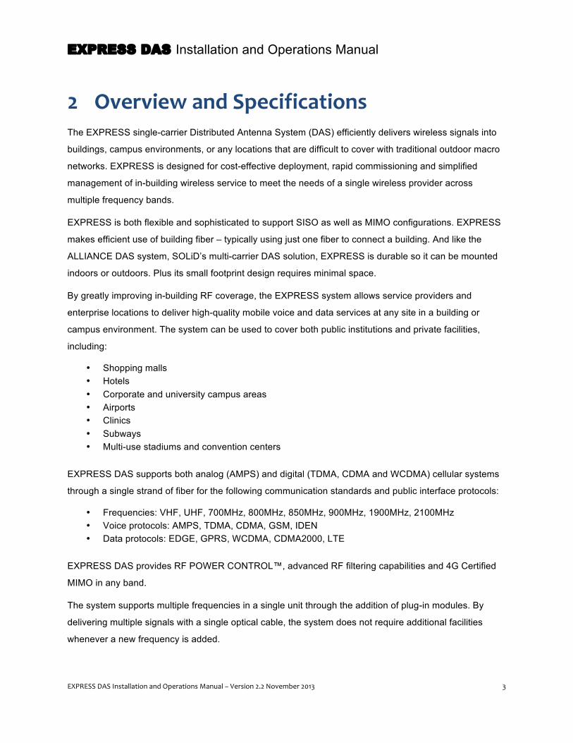
2 Overview and Specifications The EXPRESS single-carrier Distributed Antenna System (DAS) efficiently delivers wireless signals into
buildings, campus environments, or any locations that are difficult to cover with traditional outdoor macro
networks. EXPRESS is designed for cost-effective deployment, rapid commissioning and simplified
management of in-building wireless service to meet the needs of a single wireless provider across
multiple frequency bands.
EXPRESS is both flexible and sophisticated to support SISO as well as MIMO configurations. EXPRESS
makes efficient use of building fiber – typically using just one fiber to connect a building. And like the
ALLIANCE DAS system, SOLiD’s multi-carrier DAS solution, EXPRESS is durable so it can be mounted
indoors or outdoors. Plus its small footprint design requires minimal space.
By greatly improving in-building RF coverage, the EXPRESS system allows service providers and
enterprise locations to deliver high-quality mobile voice and data services at any site in a building or
campus environment. The system can be used to cover both public institutions and private facilities,
including:
• Shopping malls • Hotels • Corporate and university campus areas • Airports • Clinics • Subways • Multi-use stadiums and convention centers
EXPRESS DAS supports both analog (AMPS) and digital (TDMA, CDMA and WCDMA) cellular systems
through a single strand of fiber for the following communication standards and public interface protocols:
• Frequencies: VHF, UHF, 700MHz, 800MHz, 850MHz, 900MHz, 1900MHz, 2100MHz • Voice protocols: AMPS, TDMA, CDMA, GSM, IDEN • Data protocols: EDGE, GPRS, WCDMA, CDMA2000, LTE
EXPRESS DAS provides RF POWER CONTROL™, advanced RF filtering capabilities and 4G Certified
MIMO in any band.
The system supports multiple frequencies in a single unit through the addition of plug-in modules. By
delivering multiple signals with a single optical cable, the system does not require additional facilities
whenever a new frequency is added.
EXPRESS DAS Installation and Operations Manual
4 EXPRESS DAS Installation and Operations Manual – Version 2.2 November 2013
The Express DAS platform serves two primary market segments: first as a carrier deployed coverage
enhancement product for their specific frequencies and second as a low cost, public safety / single carrier
product.
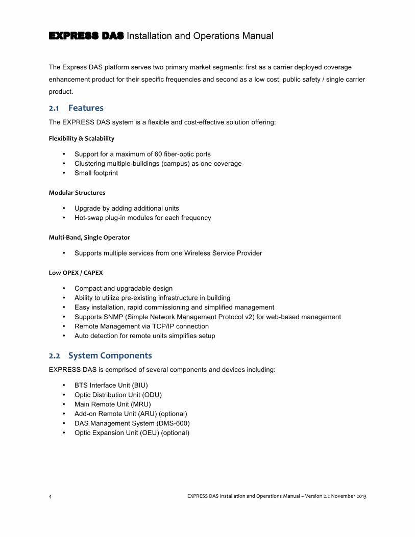
2.1 Features The EXPRESS DAS system is a flexible and cost-effective solution offering:
Flexibility & Scalability
• Support for a maximum of 60 fiber-optic ports • Clustering multiple-buildings (campus) as one coverage • Small footprint
Modular Structures
• Upgrade by adding additional units • Hot-swap plug-in modules for each frequency
Multi-‐Band, Single Operator
• Supports multiple services from one Wireless Service Provider
Low OPEX / CAPEX
• Compact and upgradable design • Ability to utilize pre-existing infrastructure in building • Easy installation, rapid commissioning and simplified management • Supports SNMP (Simple Network Management Protocol v2) for web-based management • Remote Management via TCP/IP connection • Auto detection for remote units simplifies setup
2.2 System Components EXPRESS DAS is comprised of several components and devices including:
• BTS Interface Unit (BIU) • Optic Distribution Unit (ODU) • Main Remote Unit (MRU) • Add-on Remote Unit (ARU) (optional) • DAS Management System (DMS-600) • Optic Expansion Unit (OEU) (optional)
EXPRESS DAS Installation and Operations Manual
EXPRESS DAS Installation and Operations Manual – Version 2.2 November 2013 5
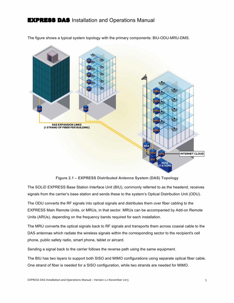
The figure shows a typical system topology with the primary components: BIU-ODU-MRU-DMS.
Figure 2.1 – EXPRESS Distributed Antenna System (DAS) Topology
The SOLiD EXPRESS Base Station Interface Unit (BIU), commonly referred to as the headend, receives
signals from the carrier’s base station and sends these to the system’s Optical Distribution Unit (ODU).
The ODU converts the RF signals into optical signals and distributes them over fiber cabling to the
EXPRESS Main Remote Units, or MRUs, in that sector. MRUs can be accompanied by Add-on Remote
Units (ARUs), depending on the frequency bands required for each installation.
The MRU converts the optical signals back to RF signals and transports them across coaxial cable to the
DAS antennae which radiate the wireless signals within the corresponding sector to the recipient's cell
phone, public safety radio, smart phone, tablet or aircard.
Sending a signal back to the carrier follows the reverse path using the same equipment.
The BIU has two layers to support both SISO and MIMO configurations using separate optical fiber cable.
One strand of fiber is needed for a SISO configuration, while two strands are needed for MIMO.

EXPRESS DAS Installation and Operations Manual
6 EXPRESS DAS Installation and Operations Manual – Version 2.2 November 2013
The DAS Management System (DMS-600) is a network management device that provides remote control
and monitoring of the DAS through a standard Internet connection.
Using a single strand of fiber, the EXPRESS ODU can feed an EXPRESS Optical Expansion Unit (OEU)
to extend the DAS from one building to others within the same campus. The OEU acts as a remote ODU
for that distant building, feeding signals to another set of remote components.
SISO (single-input and single-output) and MIMO (multiple-input and multiple output) are available in a
single unit. A MIMO configuration may be required to achieve increased communication performance –
most notably in data throughput.
2.3 SISO Configuration The figure below shows a typical SISO installation that supports four frequency bands using two modules
in the BIU. The BIU CPU and BIU Power Supply occupy two of the expansion slots leaving three slots
empty.
In this SISO environment, the connected ODU sends and receives the signal through a single fiber strand
to and from the MRU/ARUs. From there the signal is passed forward and backward along coaxial cable to
the antenna array.
Figure 2.2 – EXPRESS DAS – SISO Configuration
EXPRESS DAS Installation and Operations Manual
EXPRESS DAS Installation and Operations Manual – Version 2.2 November 2013 7
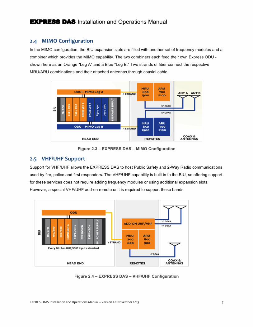
2.4 MIMO Configuration In the MIMO configuration, the BIU expansion slots are filled with another set of frequency modules and a
combiner which provides the MIMO capability. The two combiners each feed their own Express ODU -
shown here as an Orange "Leg A" and a Blue "Leg B." Two strands of fiber connect the respective
MRU/ARU combinations and their attached antennas through coaxial cable.
Figure 2.3 – EXPRESS DAS – MIMO Configuration
2.5 VHF/UHF Support Support for VHF/UHF allows the EXPRESS DAS to host Public Safety and 2-Way Radio communications
used by fire, police and first responders. The VHF/UHF capability is built in to the BIU, so offering support
for these services does not require adding frequency modules or using additional expansion slots.
However, a special VHF/UHF add-on remote unit is required to support these bands.
Figure 2.4 – EXPRESS DAS – VHF/UHF Configuration

EXPRESS DAS Installation and Operations Manual
8 EXPRESS DAS Installation and Operations Manual – Version 2.2 November 2013
2.6 System Capacities • Each BIU supports one sector and up 6 bands (SISO and MIMO are supported for all bands). • Each BIU can drive up to 8 ODUs (four on the SISO leg and four on the MIMO leg). • Each BIU can support up to four OEUs. • Each ODU can drive up to eight MRUs (or six MRUs and two OEUs). • Only one strand of fiber is needed to connect each MRU or OEU. • Each BIU can support up to four OEUs • Each OEU can support up to eight MRU/ARUs • The DMS-600 can support up to 16 sectors or BIUs.
EXPRESS DAS Installation and Operations Manual
EXPRESS DAS Installation and Operations Manual – Version 2.2 November 2013 9
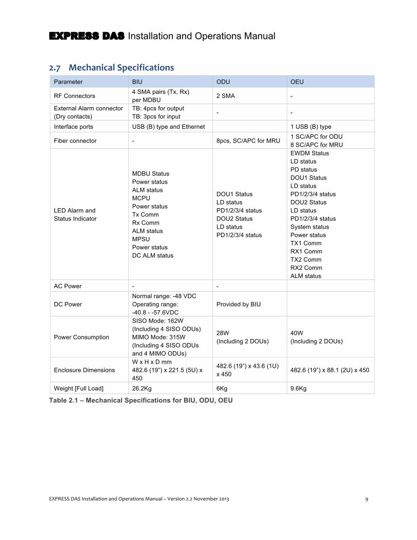
2.7 Mechanical Specifications Parameter BIU ODU OEU
RF Connectors 4 SMA pairs (Tx, Rx) per MDBU
2 SMA -
External Alarm connector (Dry contacts)
TB: 4pcs for output TB: 3pcs for input
- -
Interface ports USB (B) type and Ethernet 1 USB (B) type
Fiber connector - 8pcs, SC/APC for MRU 1 SC/APC for ODU 8 SC/APC for MRU
LED Alarm and Status Indicator
MDBU Status Power status ALM status MCPU Power status Tx Comm Rx Comm ALM status MPSU Power status DC ALM status
DOU1 Status LD status PD1/2/3/4 status DOU2 Status LD status PD1/2/3/4 status
EWDM Status LD status PD status DOU1 Status LD status PD1/2/3/4 status DOU2 Status LD status PD1/2/3/4 status System status Power status TX1 Comm RX1 Comm TX2 Comm RX2 Comm ALM status
AC Power - -
DC Power Normal range: -48 VDC Operating range: -40.8 - -57.6VDC
Provided by BIU
Power Consumption
SISO Mode: 162W (Including 4 SISO ODUs) MIMO Mode: 315W (Including 4 SISO ODUs and 4 MIMO ODUs)
28W (Including 2 DOUs)
40W (Including 2 DOUs)
Enclosure Dimensions W x H x D mm 482.6 (19”) x 221.5 (5U) x 450
482.6 (19”) x 43.6 (1U) x 450
482.6 (19”) x 88.1 (2U) x 450
Weight [Full Load] 26.2Kg 6Kg 9.6Kg
Table 2.1 – Mechanical Specifications for BIU, ODU, OEU
EXPRESS DAS Installation and Operations Manual
10 EXPRESS DAS Installation and Operations Manual – Version 2.2 November 2013
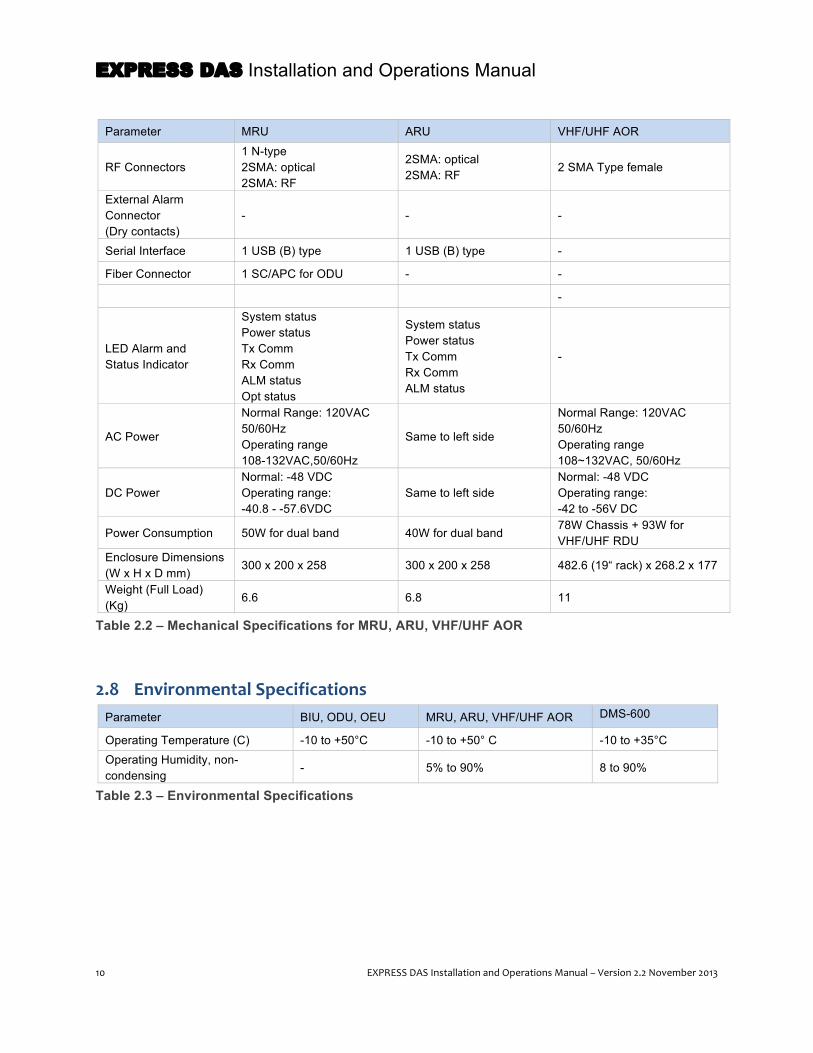
Parameter MRU ARU VHF/UHF AOR
RF Connectors 1 N-type 2SMA: optical 2SMA: RF
2SMA: optical 2SMA: RF
2 SMA Type female
External Alarm Connector (Dry contacts)
- - -
Serial Interface 1 USB (B) type 1 USB (B) type -
Fiber Connector 1 SC/APC for ODU - -
-
LED Alarm and Status Indicator
System status Power status Tx Comm Rx Comm ALM status Opt status
System status Power status Tx Comm Rx Comm ALM status
-
AC Power
Normal Range: 120VAC 50/60Hz Operating range 108-132VAC,50/60Hz
Same to left side
Normal Range: 120VAC 50/60Hz Operating range 108~132VAC, 50/60Hz
DC Power Normal: -48 VDC Operating range: -40.8 - -57.6VDC
Same to left side Normal: -48 VDC Operating range: -42 to -56V DC
Power Consumption 50W for dual band 40W for dual band 78W Chassis + 93W for VHF/UHF RDU
Enclosure Dimensions (W x H x D mm)
300 x 200 x 258 300 x 200 x 258 482.6 (19“ rack) x 268.2 x 177
Weight (Full Load) (Kg)
6.6 6.8 11
Table 2.2 – Mechanical Specifications for MRU, ARU, VHF/UHF AOR
2.8 Environmental Specifications Parameter BIU, ODU, OEU MRU, ARU, VHF/UHF AOR DMS-600
Operating Temperature (C) -10 to +50°C -10 to +50° C -10 to +35°C Operating Humidity, non-condensing
- 5% to 90% 8 to 90%
Table 2.3 – Environmental Specifications
EXPRESS DAS Installation and Operations Manual
EXPRESS DAS Installation and Operations Manual – Version 2.2 November 2013 11
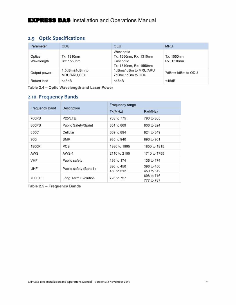
2.9 Optic Specifications Parameter ODU OEU MRU
Optical Wavelength
Tx: 1310nm Rx: 1550nm
West optic Tx: 1550nm, Rx: 1310nm East optic Tx: 1310nm, Rx: 1550nm
Tx: 1550nm Rx: 1310nm
Output power 1.5dBm±1dBm to MRU/ARU,OEU
1dBm±1dBm to MRU/ARU 7dBm±1dBm to ODU 7dBm±1dBm to ODU
Return loss <45dB <45dB <45dB
Table 2.4 – Optic Wavelength and Laser Power
2.10 Frequency Bands
Frequency Band Description Frequency range
Tx(MHz) Rx(MHz)
700PS P25/LTE 763 to 775 793 to 805
800PS Public Safety/Sprint 851 to 869 806 to 824
850C Cellular 869 to 894 824 to 849
900i SMR 935 to 940 896 to 901
1900P PCS 1930 to 1995 1850 to 1915
AWS AWS-1 2110 to 2155 1710 to 1755
VHF Public safety 136 to 174 136 to 174
UHF Public safety (Band1) 396 to 450 450 to 512
396 to 450 450 to 512
700LTE Long Term Evolution 728 to 757 698 to 716 777 to 787
Table 2.5 – Frequency Bands

EXPRESS DAS Installation and Operations Manual
12 EXPRESS DAS Installation and Operations Manual – Version 2.2 November 2013
2.11 Band Specifications The Express DAS platform allows many band combinations as well as different output power levels within
the band depending on the combination.
2.11.1 Output Power Level
Band Specifications 700PS 700LTE 800 850C 900i+PA 1900P AWS-1 VHF UHF
MRU ARU 850/1900P 700LTE/AWS - 24dBm - 24dBm - 28dBm 28dBm
24dBm 24dBm 1900 800/900 - - 25dBm - 25dBm 30dBm - 1900 - - - - - 30dBm - 850/1900 - - - 25dBm - 30dBm - 700PS/800 800/900 21dBm - 21dBm - 21dBm - -
Table 2.6 – Output Power Level By Band
2.11.2 RF Specifications
Item 700PS 700LTE 800 850C 900i+PA 1900P AWS-1 VHF UHF
Downlink Gain 41dB 44dB 45(41)dB 44(45,41)dB 45(41)dB 48(50)dB 48(50)dB 14-39dB 14-39dB
TX Freq. Range (MHz)
764-776 728-757 851-869 869-894 929-941 1930-1995 2110-2155
136-174 385-512
RX Freq. Range (MHz)
794-806 698-716 777-787
806-824 824-849 896-902 1850-1915 1710-1755
136-174 385-512
Gain Control Range RX
20dB/step 1dB
Spurious <-13dBm Optical Link AGC
Above 10dB
VSWR 1.4 max Passband ripple
5dBp-p per Band
Optic Link Loss Max 5dBo Optic Wavelength
1310nm/1550nm with WDM
Uplink Output Power
0dBm/Total each band
Uplink Input Power
-50dBm max
Noise Figure 700PS, 700PS/800+800/900: 12dB;
700LTE, 1900+800/900, 850C, 900i+PA, 1900P, AWS: 8dB; VHF/UHF: 7dB
Uplink Gain 30-50dB 25dB – 45dB Gain Control Range TX
25dB in 1dB steps
Table 2.7 – RF Specifications
EXPRESS DAS Installation and Operations Manual
EXPRESS DAS Installation and Operations Manual – Version 2.2 November 2013 13
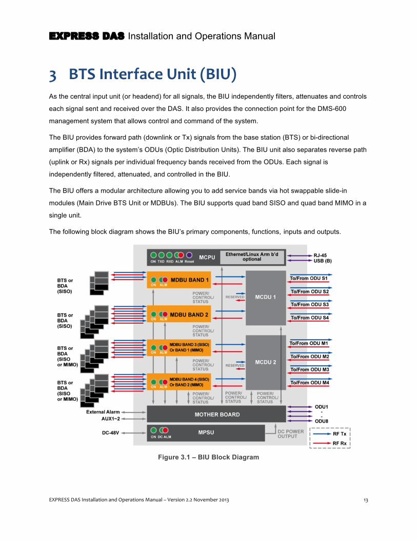
3 BTS Interface Unit (BIU) As the central input unit (or headend) for all signals, the BIU independently filters, attenuates and controls
each signal sent and received over the DAS. It also provides the connection point for the DMS-600
management system that allows control and command of the system.
The BIU provides forward path (downlink or Tx) signals from the base station (BTS) or bi-directional
amplifier (BDA) to the system’s ODUs (Optic Distribution Units). The BIU unit also separates reverse path
(uplink or Rx) signals per individual frequency bands received from the ODUs. Each signal is
independently filtered, attenuated, and controlled in the BIU.
The BIU offers a modular architecture allowing you to add service bands via hot swappable slide-in
modules (Main Drive BTS Unit or MDBUs). The BIU supports quad band SISO and quad band MIMO in a
single unit.
The following block diagram shows the BIU’s primary components, functions, inputs and outputs.
Figure 3.1 – BIU Block Diagram

EXPRESS DAS Installation and Operations Manual
14 EXPRESS DAS Installation and Operations Manual – Version 2.2 November 2013
3.1 BIU Specifications The BIU mounts in a standard 19-inch rack mount frame and occupies five rack units (5U). The unit is
powered from a separate DC Power Supply shelf.
Figure 3.2 – BIU Dimensions

EXPRESS DAS Installation and Operations Manual
EXPRESS DAS Installation and Operations Manual – Version 2.2 November 2013 15
3.1.1 BIU Mechanical Specifications
Specification Value
Downlink Input Power -20 - +10dBm
Uplink Output Power -25 - 0dBm
Nominal Impedance 50 ohm
Power Supply Voltage Range -48V (DC : -42V - -56V)
Voltage Standing Wave Ratio VSWR 1.5:1 at all in& out ports
Monitoring level at MDBU - 20dB
Mounting Type 19” Rack Mounting
Size (W x H x D mm) 482.6 (19“) x 221 (5U) x 450
In & Output Port Type SMA Female
Front Panel LED Indicator
SC_MDBU Power on: Green, Alarm: Red
SC_MCPU Power on: Green, Alarm: Red LED flickering: Communication Status
SC_MPSU Power on: Green, Alarm: Red
Maximum Power Consumption 168W with 4 ODUs powered
Total Max Weight
SC_BIU_SISO 24.6kg
SC_BIU_MIMO 26.2kg
Power consumption SISO Mode: 168 W (Including 4 SISO ODUs) MIMO Mode: 315W (Including 4 SISO ODUs and 4 MIMO ODUs)
Type Approval & Certification UL (UL60950-1), FCC
EMC FCC Part15 compliant
Table 3.1 – BIU Mechanical Specifications
3.1.2 BIU Environmental Data
Specification Value
Environmental Condition In-door use only
Operating Temperature (Celsius) -10° to +50°C
Operating Humidity 5 to 90% non-condensing
Table 3.2 – BIU Environmental Data

EXPRESS DAS Installation and Operations Manual
16 EXPRESS DAS Installation and Operations Manual – Version 2.2 November 2013
3.2 BIU Components The BIU is comprised of several components, which are described in detail below.
Figure 3.3 – BIU Components
Unit Name Product No Description
Chassis
SC_BIU_SISO SC_BIU_MIMO
SC_BIU_SISO: Includes MPSU Card, MCPU Card, MCDU Card,1 MCDU Blank and 2 MDBU Blanks SC_BIU_MIMO: Includes MPSU Card, MCPU Card and 2 MCDU Cards
Mother Board
Provides signal interface and power for each unit, four ports for dry contact output, three ports for input, two Aux ports for future usage
Main Drive BTS Unit (MDBU)
SC_MDBU Amplify & adjust downlink RF signal Amplify & adjust uplink RF signal Max. 4 MDBUs in a single BIU
Main Combiner Divider Unit (MCDU)
SC_MCDU
Combines 4 downlink signals and divides 4 uplink signal to ODU Combines 4 uplink signals and divides 4 downlink signals to MDBU Supports VHF/UHF interface port
Main Central Processor Unit (MCPU)
SC_MCPU Controls and monitors system status Control and monitoring with USB (B) Allows access via the Internet through Ethernet port
Main Power Supply Unit (MPSU)
SC_MPSU Input power: DC -48V, Output power: 9V, 6V
Blank Card SC_MCDU_B Blank card for unused slot
Table 3.3 – BIU Components and Functions
MDBU #2
MDBU #1
MDBU #3
MDBU #4
SISO Side MIMO Side
MCDU’s MPSU

EXPRESS DAS Installation and Operations Manual
EXPRESS DAS Installation and Operations Manual – Version 2.2 November 2013 17
Unit Name Dimension (W x H x D) (mm)
Weight (Kg) Power Consumption (W)
BTS Interface Unit – SISO 482.6 (19”) x 221 (5U) x 450 13.2 7.2
BTS Interface Unit – MIMO 482.6 (19”) x 221 (5U) x 450 14.2 9.6
Main Central Processor Unit 40 x 202.5 x 289.5 0.8 4.8
Main Power Supply Unit 65 x 202.5 x 294.5 2.3
Main Combiner/Divider Unit 48.5 x 202.5 x 282.9 2 2.4
BIU Blank Card 48.5 x 202.5 x 282.9 0.3 -
56.3 x 202.5 x 282.9 0.3 -
MDBU 1900PCS + 850 Cellular 56.3 x 202.5 x 282.9 3.0 16
MDBU 700LTE + AWS 56.3 x 202.5 x 282.9 3.0 16
MDBU 1900PCS 56.3 x 202.5 x 282.9 3.0 9
MDBU 800 IDEN + 900 IDEN 56.3 x 202.5 x 282.9 3.0 16
Table 3.4 – BIU Components -- Power Consumption, Weight and Dimension

EXPRESS DAS Installation and Operations Manual
18 EXPRESS DAS Installation and Operations Manual – Version 2.2 November 2013
3.2.1 Main Drive BTS Unit (MDBU)
The MDBU delivers downlink signals from the base station or BDA to mobile devices, and it delivers
uplink signals from the devices to the BTS or BDA. The unit monitors downlink input levels and can
automatically adjust input attenuation (ATT) using an Automatic Gain Control (AGC) function. It also uses
attenuation to adjust the uplink gain.
A green LED on the front panel indicates power to the unit as well as power to the individual modules. A
red LED indicates an alarm condition, meaning the module is connected to a signal source but there is an
abnormal signal level.
Figure 3.4 – MDBU at a glance
The MONITOR SMA ports seen at the MDBU front panel enable you to check the current levels of the downlink input and uplink output signals in current service without affecting the main service signals. THESE PORTS ARE USED FOR TESTING PURPOSES ONLY. All signal source connections are done on the back of the MDBU.
EXPRESS DAS Installation and Operations Manual
EXPRESS DAS Installation and Operations Manual – Version 2.2 November 2013 19
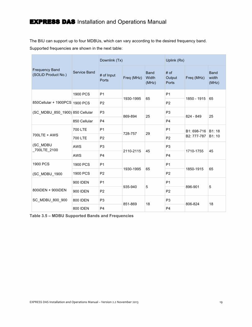
The BIU can support up to four MDBUs, which can vary according to the desired frequency band.
Supported frequencies are shown in the next table:
Frequency Band (SOLiD Product No.)
Service Band
Downlink (Tx) Uplink (Rx)
# of Input Ports
Freq (MHz) Band Width (MHz)
# of Output Ports
Freq (MHz) Band width (MHz)
850Cellular + 1900PCS (SC_MDBU_850_1900)
1900 PCS P1 1930-1995 65
P1 1850 - 1915 65
1900 PCS P2 P2
850 Cellular P3 869-894 25
P3 824 - 849 25
850 Cellular P4 P4
700LTE + AWS (SC_MDBU _700LTE_2100
700 LTE P1 728-757 29
P1 B1: 698-716 B2: 777-787
B1: 18 B1: 10 700 LTE P2 P2
AWS P3 2110-2115 45
P3 1710-1755 45
AWS P4 P4
1900 PCS (SC_MDBU_1900
1900 PCS P1 1930-1995 65
P1 1850-1915 65
1900 PCS P2 P2
800iDEN + 900iDEN SC_MDBU_800_900
900 IDEN P1 935-940 5
P1 896-901 5
900 IDEN P2 P2
800 IDEN P3 851-869 18
P3 806-824 18
800 IDEN P4 P4
Table 3.5 – MDBU Supported Bands and Frequencies

EXPRESS DAS Installation and Operations Manual
20 EXPRESS DAS Installation and Operations Manual – Version 2.2 November 2013
3.2.2 Main Combiner Divider Unit (MCDU)
The MCDU combines downlink signals received from the MDBUs, per frequency band, and then splits
them for delivery to the system’s Optic Distribution Units (ODUs). For the reverse path, it combines uplink
signals from each of the ODUs and then divides them for delivery to the individual MDBUs. The unit
supports attenuation (ATT) for input monitoring and input control.
The MCDU has a built-in port to interface with VHF/UHF signals from public safety and 2-way radio
systems.
Figure 3.5 – MCDU at a Glance
The MCDU supports the VHF/UHF frequency band as shown in the following table:
Unit name Manufacturer Product No
Description In/out RF Port
Tx Rx
VHF/UHF SC_MCDU Combining and dividing input signals to send to ODUs 1 Port 1 Port
Table 3.6 – MCDU – VHF/UHF Frequency Band
EXPRESS DAS Installation and Operations Manual
EXPRESS DAS Installation and Operations Manual – Version 2.2 November 2013 21
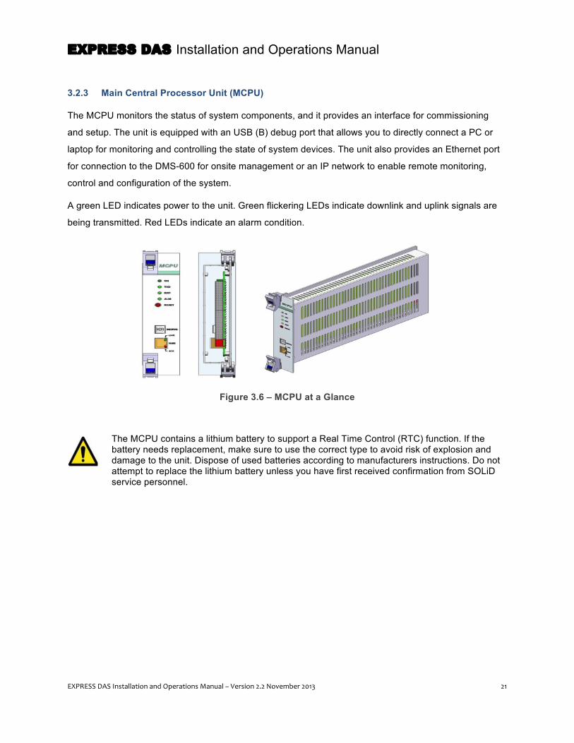
3.2.3 Main Central Processor Unit (MCPU)
The MCPU monitors the status of system components, and it provides an interface for commissioning
and setup. The unit is equipped with an USB (B) debug port that allows you to directly connect a PC or
laptop for monitoring and controlling the state of system devices. The unit also provides an Ethernet port
for connection to the DMS-600 for onsite management or an IP network to enable remote monitoring,
control and configuration of the system.
A green LED indicates power to the unit. Green flickering LEDs indicate downlink and uplink signals are
being transmitted. Red LEDs indicate an alarm condition.
Figure 3.6 – MCPU at a Glance
The MCPU contains a lithium battery to support a Real Time Control (RTC) function. If the battery needs replacement, make sure to use the correct type to avoid risk of explosion and damage to the unit. Dispose of used batteries according to manufacturers instructions. Do not attempt to replace the lithium battery unless you have first received confirmation from SOLiD service personnel.

EXPRESS DAS Installation and Operations Manual
22 EXPRESS DAS Installation and Operations Manual – Version 2.2 November 2013
3.2.4 Main Power Supply Unit (MPSU)
The BIU requires -48v power, which is provided by a rack mounted DC power supply unit connected to
the Main Power Supply Unit (MPSU) in the BIU. The MPSU delivers +6V and +9V DC power for
components in the BIU and ODU. On the front panel, the MPSU has an output test port and LEDs to
indicate power to the unit, DC Alarms and other fault conditions. You can also access the power on/off
switch for the unit at the front panel.
Figure 3.7 – MPSU at a Glance
EXPRESS DAS Installation and Operations Manual
EXPRESS DAS Installation and Operations Manual – Version 2.2 November 2013 23
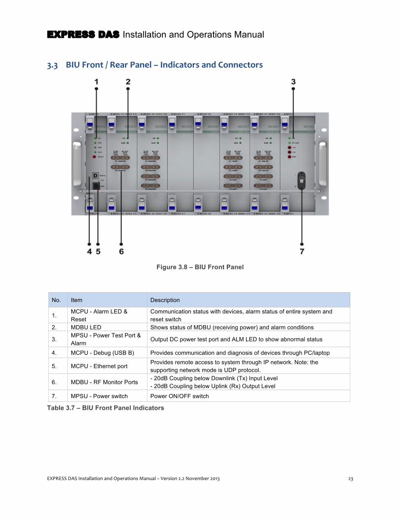
3.3 BIU Front / Rear Panel – Indicators and Connectors
Figure 3.8 – BIU Front Panel
No. Item Description
1. MCPU - Alarm LED & Reset
Communication status with devices, alarm status of entire system and reset switch
2. MDBU LED Shows status of MDBU (receiving power) and alarm conditions
3. MPSU - Power Test Port & Alarm
Output DC power test port and ALM LED to show abnormal status
4. MCPU - Debug (USB B) Provides communication and diagnosis of devices through PC/laptop
5. MCPU - Ethernet port Provides remote access to system through IP network. Note: the supporting network mode is UDP protocol.
6. MDBU - RF Monitor Ports - 20dB Coupling below Downlink (Tx) Input Level - 20dB Coupling below Uplink (Rx) Output Level
7. MPSU - Power switch Power ON/OFF switch
Table 3.7 – BIU Front Panel Indicators

EXPRESS DAS Installation and Operations Manual
24 EXPRESS DAS Installation and Operations Manual – Version 2.2 November 2013
Figure 3.9 – BIU Rear Panel
No. Item Description
1. DC Input Port Input terminal for DC -48V
2. External ALM Port Input/output terminal for dry contact
3. GND Port System ground terminal
4. AUX I/O Port Reserved Port for future uses
5. MIMO ODU I/O Port RF signal interface terminal for ODU
6. MIMO ODU signal Port Power and signal interface terminal for ODU
7. MIMO BTS/BDA I/O Port Input/output interface terminal of BTS/BDA
8. VHF/UHF I/O Port RF signal interface terminal of VHF/UHF
9. SISO ODU I/O Port RF signal interface terminal for ODU
10. SISO ODU signal Port Power and signal interface terminal for ODU
11. SISO BTS/BDA I/O Port Input/output interface terminal of BTS/BDA
Table 3.8 – BIU Rear Panel Connectors
Coax wiring connecting each signal source at the back of the unit comes factory pre-installed to simplify installation. DO NOT ATTEMPT TO CHANGE THIS WIRING.
2
3
EXPRESS DAS Installation and Operations Manual
EXPRESS DAS Installation and Operations Manual – Version 2.2 November 2013 25
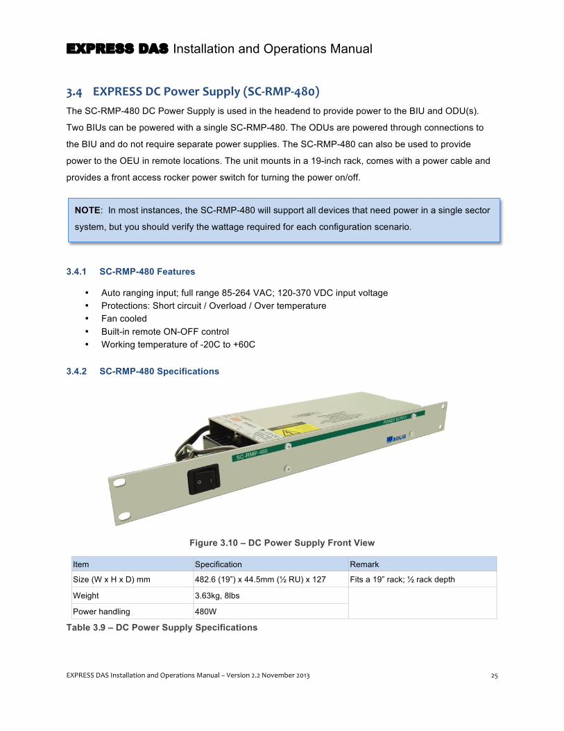
3.4 EXPRESS DC Power Supply (SC-‐RMP-‐480) The SC-RMP-480 DC Power Supply is used in the headend to provide power to the BIU and ODU(s).
Two BIUs can be powered with a single SC-RMP-480. The ODUs are powered through connections to
the BIU and do not require separate power supplies. The SC-RMP-480 can also be used to provide
power to the OEU in remote locations. The unit mounts in a 19-inch rack, comes with a power cable and
provides a front access rocker power switch for turning the power on/off.
3.4.1 SC-RMP-480 Features
• Auto ranging input; full range 85-264 VAC; 120-370 VDC input voltage • Protections: Short circuit / Overload / Over temperature • Fan cooled • Built-in remote ON-OFF control • Working temperature of -20C to +60C
3.4.2 SC-RMP-480 Specifications
Figure 3.10 – DC Power Supply Front View
Item Specification Remark
Size (W x H x D) mm 482.6 (19”) x 44.5mm (½ RU) x 127 Fits a 19” rack; ½ rack depth
Weight 3.63kg, 8lbs
Power handling 480W
Table 3.9 – DC Power Supply Specifications
NOTE: In most instances, the SC-RMP-480 will support all devices that need power in a single sector
system, but you should verify the wattage required for each configuration scenario.

EXPRESS DAS Installation and Operations Manual
26 EXPRESS DAS Installation and Operations Manual – Version 2.2 November 2013
4 Optical Distribution Unit (ODU) The ODU contains an internal optical transmitter and receiver allowing it to perform RF and optical signal
conversions. The ODU receives incoming downlink RF signals from the BIU and converts them into
optical signals. It then sends the optical signals to remote MRUs/ARUs through fiber optic cables. For the
reverse path, the ODU converts optical signals received from the MRUs/ARUs to RF signals attenuated
at -20dbm and sends them to the BIU.
The following block diagram shows the ODU’s primary components, functions, inputs and outputs.
Figure 4.1 – ODU Block Diagram

EXPRESS DAS Installation and Operations Manual
EXPRESS DAS Installation and Operations Manual – Version 2.2 November 2013 27
4.1 ODU Specifications The ODU mounts in a standard 19-inch rack frame and occupies one rack unit (1U). The ODU is
generally co-located with the BIU from which it receives power and RF communication. Two coax cables
and a power supply cable connect the two units. Up to eight ODUs can be connected with the BIU, four
for the SISO and four for the MIMO paths. Each ODU can hold two Donor Optic Units, and each DOU
supports four optical ports. Therefore, each ODU can provide connections to eight MRUs (or six MRUs
and two OEUs).
Figure 4.2 – ODU Dimensions

EXPRESS DAS Installation and Operations Manual
28 EXPRESS DAS Installation and Operations Manual – Version 2.2 November 2013
4.1.1 ODU Mechanical Specifications
Specification Value
Downlink Input Power -8dBm (VHF/UFH : -15dBm)
Uplink Output Power -9dBm (VHF/UFH : -10dBm)
Nominal Impedance 50 ohm
Input Voltage DC +9V
Voltage Standing Wave Ratio (VSWR) 1.8:1 at all in& out ports
Mounting Type 19” Rack Mounting (1U height)
Size (W x H x D) mm 482.6 (19") x 43.6 (1U) x 450
In & Output Port Type SMA Female
Front Panel LED Indicator
LD Power on: Green, Alarm: Red
PD1 - PD4 Power on: Green, Alarm: Red LED flickering: Communication Status
Total Max Weight 5.9 kg
Type Approval & Certification UL(UL60950-1), FCC
EMC FCC Part15 compliant
Power consumption 28.2 W
Table 4.1 – ODU Mechanical Specifications
4.1.2 ODU Environmental Data
Specification Value
Environmental Condition Indoor use only
Operating Temperature (°C) -10° to +50°C
Operating Humidity 5 to 90% non-condensing
Table 4.2 – ODU Environmental Data
EXPRESS DAS Installation and Operations Manual
EXPRESS DAS Installation and Operations Manual – Version 2.2 November 2013 29
4.2 ODU Components The principal ODU component is the Donor Optic Unit, which is described below.
Unit Name
Manufacturer Product No.
Description Remark
Optical Distribution Unit Chassis
SC_ODU_C Common part that accepts DOUs. Provides RF connections to/from BIU.
Donor Optic Unit SC_ODU OM 4
Four Port Optical Unit that converts Downlink (Tx) RF signals into optical signals and converts Uplink (Rx) optical signals into RF signals
Four optical ports per DOU. Two DOUs per one ODU.
ODU Blank Card SC_ODU_B (ODU BLANK)
Blank card for unused slot
Table 4.3 – ODU Components
Unit Name Dimension (WxHxD) (mm) Weight (kg) Power Consumption (W) Optical Distribution Unit Chassis
482.6 (19”) x 43.6 (1U) x 450 2.5 1.2
4 Port Donor Optic Unit 169 x 33 x 302 1.7 13.5
Blank Card 169 x 33 x 302 0.4 -
Table 4.4 – ODU Components – Mechanical Specifications
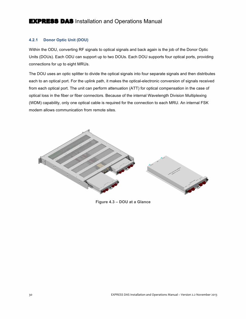
EXPRESS DAS Installation and Operations Manual
30 EXPRESS DAS Installation and Operations Manual – Version 2.2 November 2013
4.2.1 Donor Optic Unit (DOU)
Within the ODU, converting RF signals to optical signals and back again is the job of the Donor Optic
Units (DOUs). Each ODU can support up to two DOUs. Each DOU supports four optical ports, providing
connections for up to eight MRUs.
The DOU uses an optic splitter to divide the optical signals into four separate signals and then distributes
each to an optical port. For the uplink path, it makes the optical-electronic conversion of signals received
from each optical port. The unit can perform attenuation (ATT) for optical compensation in the case of
optical loss in the fiber or fiber connectors. Because of the internal Wavelength Division Multiplexing
(WDM) capability, only one optical cable is required for the connection to each MRU. An internal FSK
modem allows communication from remote sites.
Figure 4.3 – DOU at a Glance
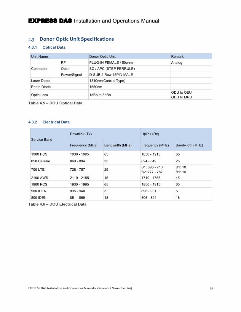
EXPRESS DAS Installation and Operations Manual
EXPRESS DAS Installation and Operations Manual – Version 2.2 November 2013 31
4.3 Donor Optic Unit Specifications 4.3.1 Optical Data
Unit Name Donor Optic Unit Remark
Connector RF PLUG-IN FEMALE / 50ohm Analog Optic SC / APC (STEP FERRULE)
Power/Signal D-SUB 2 Row 15PIN MALE
Laser Diode 1310nm(Coaxial Type)
Photo Diode 1550nm
Optic Loss 1dBo to 5dBo ODU to OEU
ODU to MRU Table 4.5 – DOU Optical Data
4.3.2 Electrical Data
Service Band Downlink (Tx) Uplink (Rx) Frequency (MHz) Bandwidth (MHz) Frequency (MHz) Bandwidth (MHz)
1900 PCS 1930 - 1995 65 1850 - 1915 65 850 Cellular 869 - 894 25 824 - 849 25 700 LTE 728 - 757 29 B1: 698 - 716
B2: 777 - 787 B1: 18 B1: 10
2100 AWS 2110 - 2155 45 1710 - 1755 45 1900 PCS 1930 - 1995 65 1850 - 1915 65 900 IDEN 935 - 940 5 896 - 901 5 800 IDEN 851 - 869 18 806 - 824 18
Table 4.6 – DOU Electrical Data
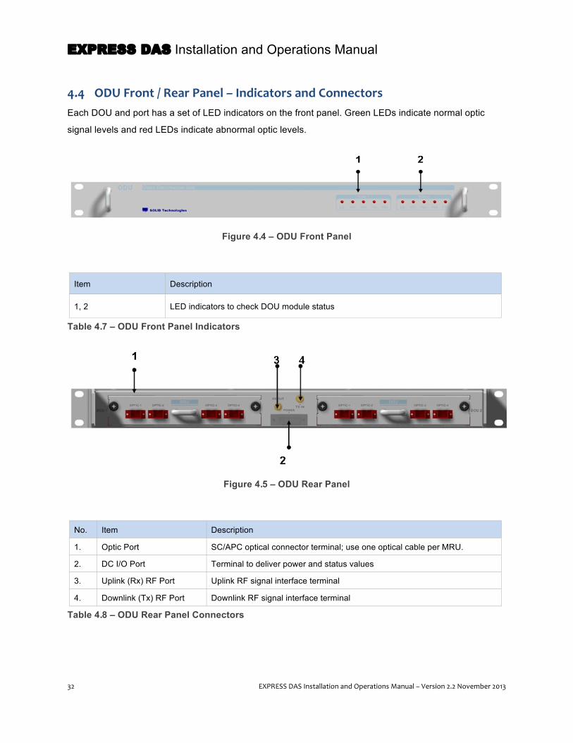
EXPRESS DAS Installation and Operations Manual
32 EXPRESS DAS Installation and Operations Manual – Version 2.2 November 2013
4.4 ODU Front / Rear Panel – Indicators and Connectors Each DOU and port has a set of LED indicators on the front panel. Green LEDs indicate normal optic
signal levels and red LEDs indicate abnormal optic levels.
Figure 4.4 – ODU Front Panel
Item Description
1, 2 LED indicators to check DOU module status
Table 4.7 – ODU Front Panel Indicators
Figure 4.5 – ODU Rear Panel
No. Item Description
1. Optic Port SC/APC optical connector terminal; use one optical cable per MRU.
2. DC I/O Port Terminal to deliver power and status values
3. Uplink (Rx) RF Port Uplink RF signal interface terminal
4. Downlink (Tx) RF Port Downlink RF signal interface terminal
Table 4.8 – ODU Rear Panel Connectors

EXPRESS DAS Installation and Operations Manual
EXPRESS DAS Installation and Operations Manual – Version 2.2 November 2013 33
5 Remote Units – MRU, ARU, VHF/UHF AOR The Main Remote Unit (MRU) receives downlink (Tx) optical signals from the ODU and converts them to
RF signals. The MRU amplifies the converted RF signals, combines them, and then delivers them to the
antenna port. When receiving uplink (Rx) signals through the antenna port, the unit filters out-of-band
signals, converts the RF signal to optical, then sends them to the ODU (or optional OEU).
The MRU comes in both single band and dual-band configurations. The optional Add-on Remote Unit
(ARU) only comes in dual-band configurations. In addition, a VHF/UHF Add on Remote (AOR) is available to
support the 450MHz UHF and 150MHz VHF bands. (See the table on page 12 for currently supported
bands.)
Because the MRU provides the connection to the ODU at the headend and to the antenna, this unit is
required in every configuration. The ARU and VHF/UHF AOR are optional add-on units and only required
to support specific bands. The ARU and AOR perform many of the same services as the MRU, but do not
contain an optical module or connection to the antenna. As an exception, the UHF/WHF AOR requires a
separate antenna connected to the unit.
Figure 5.1 – MRU/ARU Block Diagram

EXPRESS DAS Installation and Operations Manual
34 EXPRESS DAS Installation and Operations Manual – Version 2.2 November 2013
5.1 MRU/ARU Specifications The MRU and ARU cabinets are available as either indoor or outdoor models, and as either DC or AC
powered units. When installed indoors, the cabinets can be wall or rack mounted. For outdoor
installations, the cabinets are wall mounted either side-by-side or stacked with the ARU installed in front
of the MRU. The outdoor cabinets meet both IP65 and NEMA 4 specifications for outdoor enclosures.
The MRU and ARU have the same form factor. Dimensions are shown in the next figure.
Figure 5.2 – MRU/ARU Dimensions

EXPRESS DAS Installation and Operations Manual
EXPRESS DAS Installation and Operations Manual – Version 2.2 November 2013 35
5.1.1 MRU/ARU Mechanical Specifications
Specification Value
Uplink Input Power -30 ~50dBm
Nominal Impedance 50 ohm
Power Supply Voltage Range AC90 ~264V, Output Voltage: +25V DC: -48V(-42 to -56V), Output DC: +25V
Voltage Standing Wave Ratio (VSWR) 1.6:1 at all in and out ports
Mounting Type Wall Mounting & 19” Rack Mounting
In & Output Port Type N Female & SMA Female
Front Panel LED Indicator
ON Power ON: Green, Alarm: Red
ALM Power ON: Green / Power OFF: Gray
OPT Normal: Green, Alarm: Red
TXD Green Flickering
RXD Green Flickering
Maximum Power Consumption 50W at full load
Type Approval & Certification UL (UL60950-1), FCC
EMC FCC Part 24 compliant
Table 5.1 – MRU/ARU Mechanical Specifications
5.1.2 MRU/ARU Environmental Data
Specification Value
Environmental Condition & IP Rating For indoor use, or an IP 65 / NEMA 4-rated enclosure is available for outdoor installations.
Operating Temperature (°C) -10° to +50°C
Operating Humidity 5 to 90% non-condensing
Table 5.2 – MRU/ARU Environmental Data

EXPRESS DAS Installation and Operations Manual
36 EXPRESS DAS Installation and Operations Manual – Version 2.2 November 2013
5.1.3 MRU/ARU Mechanical Specifications
Unit Name Manufacturer Product No.
Dimension (W x H x D mm)
Weight (Kg) Power
Consumption (W)
1900MHz Main Remote Unit
MRU_AC_1900 200 x 300 x 138.5 6.6
45 MRU_AC_NEMA_1900
MRU_DC_1900
MRU_DC_NEMA_1900
850MHz & 1900MHz Main Remote Unit
MRU_AC_850_1900 200 x 300 x 138.5 6.6
50 MRU_AC_NEMA_850_1900
MRU_DC_850_1900
MRU_DC_NEMA_850_1900
700MHz LTE & 2100MHz Add-on Remote Unit
ARU_AC_700LTE_2100 200 x 300 x 138.5 6.8
40 ARU_AC_NEMA_700LTE_2100
ARU_DC_700LTE_2100
ARU_DC_700LTE_NEMA_2100
800MHz & 900MHz Add-on Remote Unit
ARU_AC_800_900 200 x 300 x 138.5 6.8
44 ARU_AC_NEMA_800_900
ARU_DC_800_900
ARU_DC_NEMA_800_900 VHF/UHF AOR (includes 150/450 RDU and AC power supply)
SC_AC_150_450 482 x 268.2 x 177 13.6 78 – Chassis +
93 - RDU
VHF/UHF AOR (includes 150/450 RDU and DC power supply )
SC_DC_150_450 482 x 268.2 x 177 13.6 78 – Chassis +
93 - RDU
Flush wall mount bracket SC-BRK 482.6 x 310.3 x 157 2.8 -
Stacking ARU wall mounting kit
SC-ARU-STK 270 x 318.3 x 164 1.6 -
19" Rack MRU/ARU mounting kit
SC-RM19 482.6 x 177 x 463 6.8 -
Table 5.3 – MRU/ARU Mechanical Specifications
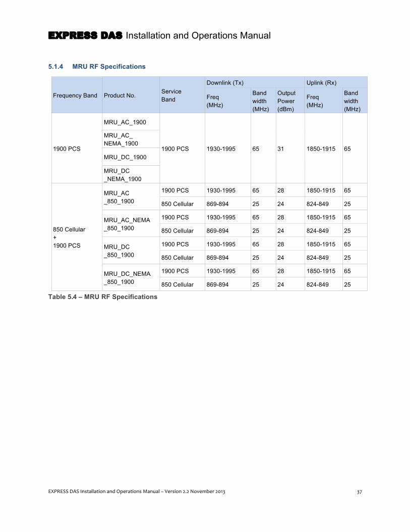
EXPRESS DAS Installation and Operations Manual
EXPRESS DAS Installation and Operations Manual – Version 2.2 November 2013 37
5.1.4 MRU RF Specifications
Frequency Band Product No. Service Band
Downlink (Tx) Uplink (Rx)
Freq (MHz)
Band width (MHz)
Output Power (dBm)
Freq (MHz)
Band width (MHz)
1900 PCS
MRU_AC_1900
1900 PCS 1930-1995 65 31 1850-1915 65
MRU_AC_ NEMA_1900
MRU_DC_1900
MRU_DC _NEMA_1900
850 Cellular + 1900 PCS
MRU_AC _850_1900
1900 PCS 1930-1995 65 28 1850-1915 65
850 Cellular 869-894 25 24 824-849 25
MRU_AC_NEMA _850_1900
1900 PCS 1930-1995 65 28 1850-1915 65
850 Cellular 869-894 25 24 824-849 25
MRU_DC _850_1900
1900 PCS 1930-1995 65 28 1850-1915 65
850 Cellular 869-894 25 24 824-849 25
MRU_DC_NEMA _850_1900
1900 PCS 1930-1995 65 28 1850-1915 65
850 Cellular 869-894 25 24 824-849 25
Table 5.4 – MRU RF Specifications

EXPRESS DAS Installation and Operations Manual
38 EXPRESS DAS Installation and Operations Manual – Version 2.2 November 2013
5.1.5 ARU RF Specifications
Frequency Band
Product No. Service Band
Downlink (Tx) Uplink (Rx)
# of Input Port
Freq (MHz)
Band width (MHz)
Output Power (dBm)
# of Output Port
Freq (MHz) Band width (MHz)
700LTE + AWS
ARU_AC _700LTE_2100
AWS LOW 728-757 29 24 LOW B1: 698-716 B2: 777-787
B1: 18 B1: 10
AWS HIGH 2110-2115
45 28 HIGH 1710-1755 45
ARU_AC_NEMA _700LTE_2100
700LTE LOW 728-757 29 24 LOW B1: 698-716 B2: 777-787
B1: 18 B1: 10
AWS HIGH 2110-2115
45 28 HIGH 1710-1755 45
ARU_DC _700LTE_2100
700LTE LOW 728-757 29 24 LOW B1: 698-716 B2: 777-787
B1: 18 B1: 10
AWS HIGH 2110-2115
45 28 HIGH 1710-1755 45
ARU_DC_ 700LTE_NEMA_2100
700LTE LOW 728-757 29 24 LOW B1: 698-716 B2: 777-787
B1: 18 B1: 10
AWS HIGH 2110-2115
45 28 HIGH 1710-1755 45
800iDEN + 900iDEN
ARU_AC_800_900 900iDEN
LOW 935 - 940 5 26
LOW 896 - 901 5
800iDEN 851 - 869 18 26 806 - 824 18
ARU_AC_NEMA _800_900
900iDEN LOW
935 - 940 5 26 LOW
896 - 901 5
800iDEN 851 - 869 18 26 806 - 824 18
ARU_DC_800_900 900iDEN
LOW 935 - 940 5 26
LOW 896 - 901 5
800iDEN 851 - 869 18 26 806 - 824 18
ARU_DC_NEMA _800_900
900iDEN LOW
935 - 940 5 26 LOW
896 - 901 5
800iDEN 851 - 869 18 26 806 - 824 18
Table 5.5 – ARU RF Specifications
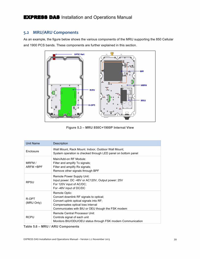
EXPRESS DAS Installation and Operations Manual
EXPRESS DAS Installation and Operations Manual – Version 2.2 November 2013 39
5.2 MRU/ARU Components As an example, the figure below shows the various components of the MRU supporting the 850 Cellular
and 1900 PCS bands. These components are further explained in this section.
Figure 5.3 – MRU 850C+1900P Internal View
Unit Name Description
Enclosure Wall Mount, Rack Mount. Indoor, Outdoor Wall Mount; System operation is checked through LED panel on bottom panel
MRFM / ARFM +BPF
Main/Add-on RF Module: Filter and amplify Tx signals; Filter and amplify Rx signals; Remove other signals through BPF
RPSU
Remote Power Supply Unit: Input power: DC -48V or AC120V, Output power: 25V For 120V input of AC/DC; For -48V input of DC/DC
R-OPT (MRU Only)
Remote Optic: Convert downlink RF signals to optical; Convert uplink optical signals into RF; Compensates optical loss interval Communicates with BIU or OEU though the FSK modem
RCPU Remote Central Processor Unit: Controls signal of each unit Monitors BIU/ODU/OEU status through FSK modem Communication
Table 5.6 – MRU / ARU Components

EXPRESS DAS Installation and Operations Manual
40 EXPRESS DAS Installation and Operations Manual – Version 2.2 November 2013
5.2.1 Main RF Module/Add-on RF Module (MRFM/ARFM) and Band Pass Filters
When receiving downlink (Tx) signals from each band through the R-Optic module, the MRFM/AFRM
filters the signals and amplifies them with the High Power Amplifier. The unit also filters uplink (Rx)
signals received through the antenna port and amplifies them as low noise to send the signals to the R-
Optic module.
The unit provides attenuation (ATT) to adjust gain. The following table shows the available units per
frequency band:
Combination Unit Name Description BPF
Cavity Filter Ceramic Filter
MRU850C + 1900P MRFM 850C+1900P Dual 1900PCS 850C
MRU1900P MRFM 1900P Single 1900PCS -
ARU700LTE + AWS ARFM 700LTE+2100AWS Dual 700LTE AWS
ARU800i + 900i ARFM800i+900i Dual 800iEN/900iDEN -
Table 5.7 – Main RF Module/Add-on RF Module (MRFM/ARFM) and Band Pass Filters
5.2.2 Remote Power Supply Unit (RPSU)
The RPSU can accept DC or AC input. The DC/DC unit accepts -48VDC and outputs +25V of DC power.
The AC/DC type takes 120V AC input and outputs +25V of DC power. The following table shows the
acceptable input ranges for each option:
Unit Range of input power
AC/DC 90 to 264 VAC
DC/DC -42V to -56VDC
Table 5.8 – Remote Power Supply Unit – Range of Input Power
When ordering the MRU / ARU, make sure to specify the power type needed for your installation. The
input cable is different depending on input voltage requirements.
NOTE: The RPSU does not have an ON/OFF power switch. The unit is active when power is
connected.

EXPRESS DAS Installation and Operations Manual
EXPRESS DAS Installation and Operations Manual – Version 2.2 November 2013 41
5.2.3 Remote Optic (R-OPT)
The Remote Optic module converts optical signals into RF signals and RF back to optical. The module
communicates with headend devices (the ODU and MDBU cards in the BIU) through an FSK modem. It
also features internal attenuation (ATT) to compensate for optical cable loss. The optical wavelength for
the downlink (Tx) path is 1310nm and for the uplink (Rx) path 1550nm. Transport is provided over a fiber
strand using WDM (Wavelength Division Multiplexing) technology.
5.2.4 Remote Central Processor Unit (RCPU)
The RCPU monitors and controls each module of the MRU and ARU. A USB (B-type) port connection
beneath the LED cover plate enables you to connect a PC and check device status through the SOLiD
software interface.
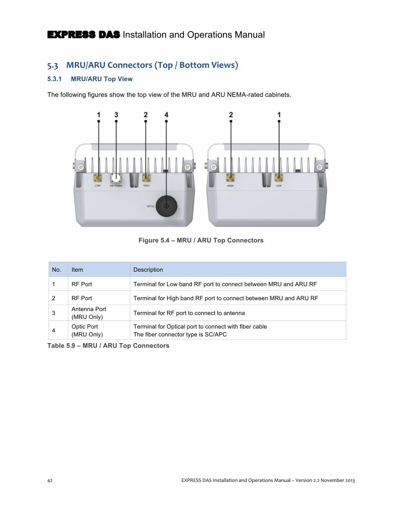
EXPRESS DAS Installation and Operations Manual
42 EXPRESS DAS Installation and Operations Manual – Version 2.2 November 2013
5.3 MRU/ARU Connectors (Top / Bottom Views) 5.3.1 MRU/ARU Top View
The following figures show the top view of the MRU and ARU NEMA-rated cabinets.
Figure 5.4 – MRU / ARU Top Connectors
No. Item Description
1 RF Port Terminal for Low band RF port to connect between MRU and ARU RF
2 RF Port Terminal for High band RF port to connect between MRU and ARU RF
3 Antenna Port (MRU Only)
Terminal for RF port to connect to antenna
4 Optic Port (MRU Only)
Terminal for Optical port to connect with fiber cable The fiber connector type is SC/APC
Table 5.9 – MRU / ARU Top Connectors

EXPRESS DAS Installation and Operations Manual
EXPRESS DAS Installation and Operations Manual – Version 2.2 November 2013 43
5.3.2 MRU/ARU Bottom View and Connectors
The following figure shows the bottom view of the MRU and ARU NEMA-rated cabinets. The bottom of
the unit is protected with a water drip edge to prevent water intrusion.
Figure 5.5 – MRU / ARU Bottom Connectors
No. Item Description
1 ARU Port (on MRU) Terminal for Tx and Rx RF ports to connect MRU to ARU Terminal for signal port to interface MRU with ARU
2 LED PANEL LED indicator panel for checking fault status. (See page 94.) USB Port to check and control device status through PC and laptop (Located below LED faceplate.)
3 VHF/UHF Port Terminal for Tx and Rx RF ports of VHF/UHF AOR Terminal for signal port to interface with VHF/UHF AOR
4 MRU Port (on ARU) Terminal for Tx and Rx RF ports to connect ARU to MRU Terminal for signal port to interface ARU with MRU
5 GND LUG PORT Terminal for system ground
6 Power Port AC 120V input port or DC-48V input port
Table 5.10 – MRU / ARU Bottom Connectors
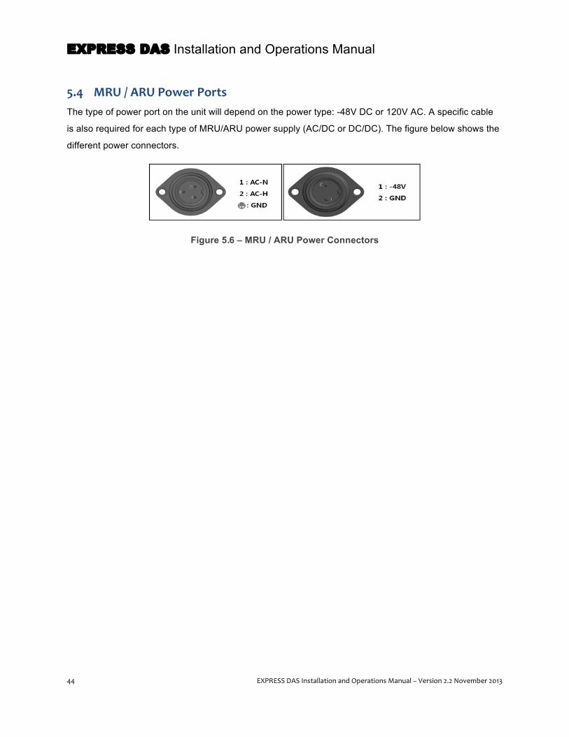
EXPRESS DAS Installation and Operations Manual
44 EXPRESS DAS Installation and Operations Manual – Version 2.2 November 2013
5.4 MRU / ARU Power Ports The type of power port on the unit will depend on the power type: -48V DC or 120V AC. A specific cable
is also required for each type of MRU/ARU power supply (AC/DC or DC/DC). The figure below shows the
different power connectors.
Figure 5.6 – MRU / ARU Power Connectors

EXPRESS DAS Installation and Operations Manual
EXPRESS DAS Installation and Operations Manual – Version 2.2 November 2013 45
5.5 VHF/UHF AOR Specifications
The AOR can mount in a standard 19-inch rack system or on a wall, either indoors or outdoors. The AOR
is rated as water, dirt and earthquake proof according to NEMA 4 standards. The unit it typically co-
located with the ROU, installed above, below or beside the ROU.
Figure 5.7 – VHF/UHF AOR at a Glance
Unit Name Dimension (W x H x D) Weight Power Consumption (W)
VHF/UHF AOR Chassis 482 mm x 268.2 mm x 177 mm 19“ W x 10.16“ H x 6.96“ D
11 Kg (24.25 lbs) 78
VHF/UHF RDU 58.9 mm x 377.9 mm x 139.7 mm 2.32” x 14.88” x 5.5”
93
Table 5.11 – VHF/UHF AOR Mechanical Specifications

EXPRESS DAS Installation and Operations Manual
46 EXPRESS DAS Installation and Operations Manual – Version 2.2 November 2013
5.5.1 Band Specifications 150MHz VHF Public Safety
Parameters Standard (Typical)
Remarks Downlink (TX) Uplink (RX)
Bandwidth 38MHz 38MHz 136 ~174MHz
System Ripple ≤5dB ≤5dB -
Input Power Level -15 to +10dBm ≤-54dBm -
Output Power +24dBm -4dBm Total
System Gain 39dB 50dB -
Gain Control Range 14 to 39dB 30 to 50dB -
IM3 -13dBm - -
IP3 - +23dBm -
Noise Figure - 7dB 1 ROU
Table 5.12 – Band Specifications 150MHz VHF Public Safety
5.5.2 Band Specifications 450MHz UHF Public Safety
Parameters Standard (Typical)
Remarks Downlink (TX) Uplink (RX)
Bandwidth 116MHz 116MHz 396-450MHz(54MHz) 450-512MHz(62MHz) Band selection
System Ripple ≤5dB ≤5dB -
Input Power Level -15 to +10dBm ≤-54dBm -
Output Power +24dBm -4dBm Total
System Gain 39dB 50dB -
Gain Control Range 14 to 39dB 30 to 50dB -
IM3 -13dBm - -
IP3 - +23dBm -
Noise Figure - 7dB 1 ROU
Table 5.13 – Band Specifications 450MHz UHF Public Safety

EXPRESS DAS Installation and Operations Manual
EXPRESS DAS Installation and Operations Manual – Version 2.2 November 2013 47
5.6 VHF/UHF AOR Components
Figure 5.8 – VHF/UHF AOR Internal View
Unit Name Product No. Description
1. VHF+UHF Remote Drive Unit
Included with Cabinets: SC_AC_150_450 and SC_DC_150_450
Filter and high amplify downlink signals; Filter and amplify uplink signals; Remove other signals through Band Pass Filtering (Note: BPF is not included with VHF+UHF module.)
2. System Interface Unit (SIU) Included with cabinet. Not field replaceable
Distributes power and signals of module
3. Add-on Remote (AOR) Power Supply (AC or DC)
Included with Cabinet
For AC Unit: Input AC 120V ; Output 27V, 9V, 6V
For DC Unit: Input DC -48V (-42--56V); Output 27V, 9V, 6V
Table 5.14 – VHF/UHF AOR Components
5.6.1 AOR Remote Drive Unit (RDU)
When receiving downlink signals for each band from the MRU’s R_Optic module, the RDU filters out-of-
band signals and amplifies them with the high power amplifier. The unit also filters uplink signals received
through the uplink antenna and amplifies them before delivering the signals to the MRU’s R_Optic module.
Only the 150 VHF / 450UHF RDU is available for the AOR used with the EXPRESS system.
NOTE: The 150 VHF / 450UHF RDU can also adjust gain, but it does not come fitted with a cavity
filter capability. External duplexers may be required but are not provided by SOLiD.”

EXPRESS DAS Installation and Operations Manual
48 EXPRESS DAS Installation and Operations Manual – Version 2.2 November 2013
5.6.2 AOR Power Supply Unit (PSU)
The AOR PSU provides power to the AOR and can accept either -48V DC or 120V AC input. Make sure
to select the appropriate model when ordering, which will also dictate the power cable that ships with the
unit. With either input, the unit provides +6V, +9V and +27V of DC power of output.
The power unit has a circuit breaker to turn the power on/off. A green LED indicates power to the unit.
5.6.3 AOR System Interface Unit (SIU)
The SIU distributes power and signals to each module. The SIU is not a field-replaceable unit.
5.7 VHF/UHF AOR Rear View Connectors
Figure 5.9 – VHF/UHF AOR Rear View Connectors
Item Description
1. VHF/UHF RX IN Terminal to receive the downlink signal from MRU
2. VHF/UHF RX OUT Terminal to receive the signals from uplink antenna
3. VHF/UHF TX OUT Terminal to transmit the uplink signal to MRU
4. Power Port Terminal to input either AC 110V or DC-48V
5. GND Lug Port Terminal to system ground
6. External Port Port to connect external equipment (not currently in supported)
7. VHF/UHF TX IN Terminal to radiate the signals to downlink antenna
Table 5.15 – VHF/UHF AOR Connectors
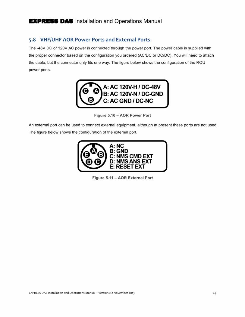
EXPRESS DAS Installation and Operations Manual
EXPRESS DAS Installation and Operations Manual – Version 2.2 November 2013 49
5.8 VHF/UHF AOR Power Ports and External Ports The -48V DC or 120V AC power is connected through the power port. The power cable is supplied with
the proper connector based on the configuration you ordered (AC/DC or DC/DC). You will need to attach
the cable, but the connector only fits one way. The figure below shows the configuration of the ROU
power ports.
Figure 5.10 – AOR Power Port
An external port can be used to connect external equipment, although at present these ports are not used.
The figure below shows the configuration of the external port.
Figure 5.11 – AOR External Port

EXPRESS DAS Installation and Operations Manual
50 EXPRESS DAS Installation and Operations Manual – Version 2.2 November 2013
6 Optic Expansion Unit (OEU) The optional OEU is designed to connect a DAS throughout multiple buildings or structures across a
campus environment, and is used primarily to drive multiple MRUs while limiting the amount of fiber
required. For example, when a signal is brought to another building, it utilizes existing fiber. To bring
service to multiple MRUs in another building would multiple strands of fiber. By utilizing the OEU, only
one strand of fiber is needed, thereby greatly reducing the amount of fiber required for these types of
configurations.
The OEU connects to the ODU, requiring only one ODU port and a single strand of fiber. It combines
downlink (Tx) signals received from the ODU and converts them to RF signals and sent to the MRU/ARUs
through fiber connections. Likewise, it receives RF signals from the MRU/ARU, converts them to optical
signals to send to the ODU.
The EXPRESS OEU can drive up to 8 MRUs. A maximum of two OEUs can be connected with the ODU,
and up to four OEU’s can be used with each BIU. The OEU uses the same Donor Optic Unit (DOU) as
the ODU, and like the ODU can support a maximum of two DOUs. The following block diagram shows the
OEU’s primary components, functions, inputs and outputs.
Figure 6.1 – OEU Block Diagram
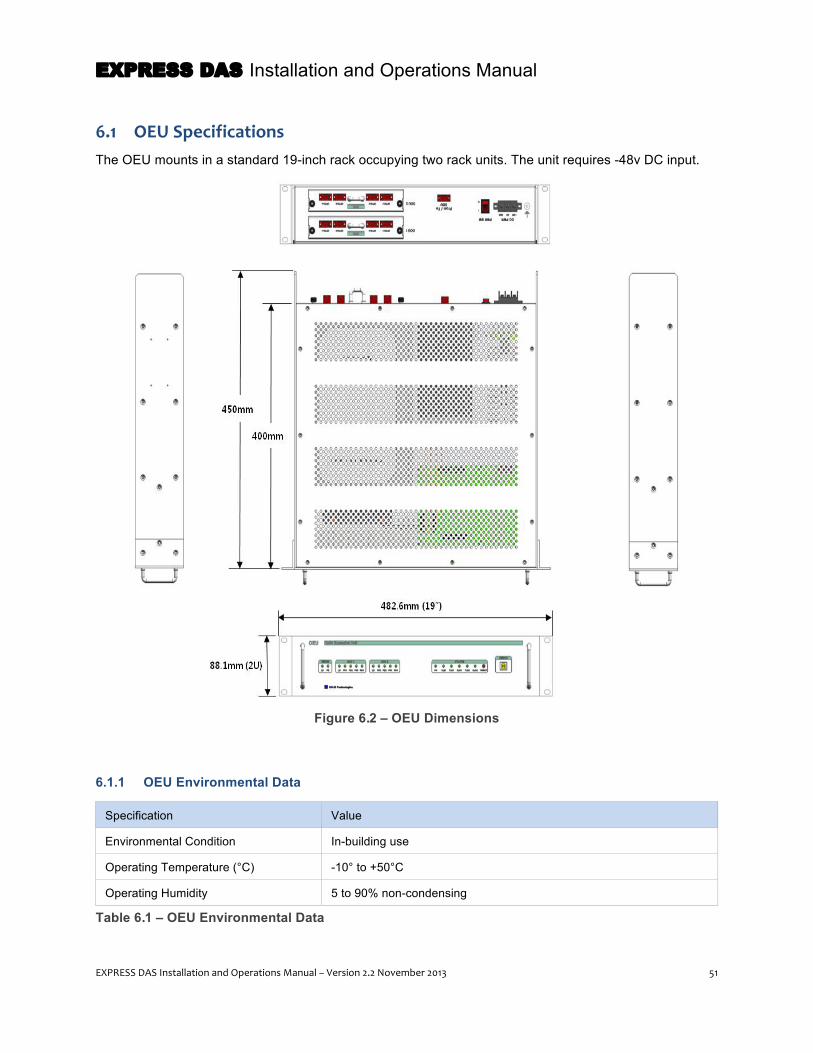
EXPRESS DAS Installation and Operations Manual
EXPRESS DAS Installation and Operations Manual – Version 2.2 November 2013 51
6.1 OEU Specifications The OEU mounts in a standard 19-inch rack occupying two rack units. The unit requires -48v DC input.
Figure 6.2 – OEU Dimensions
6.1.1 OEU Environmental Data
Specification Value
Environmental Condition In-building use
Operating Temperature (°C) -10° to +50°C
Operating Humidity 5 to 90% non-condensing
Table 6.1 – OEU Environmental Data
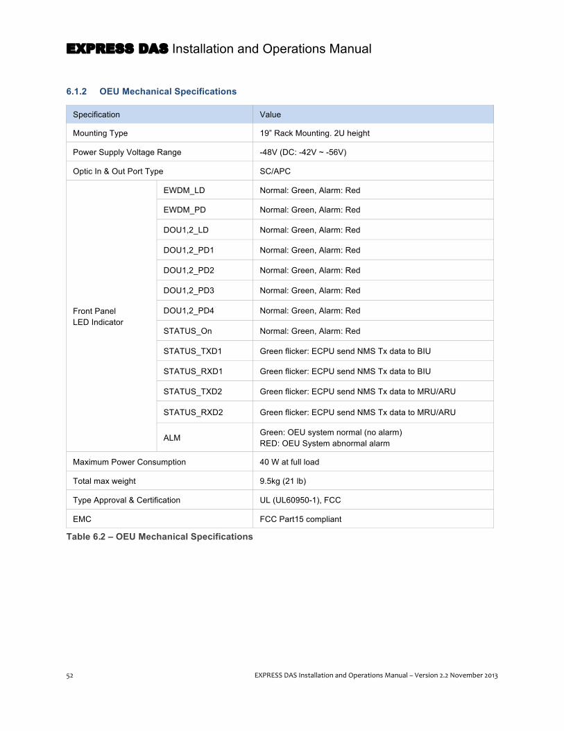
EXPRESS DAS Installation and Operations Manual
52 EXPRESS DAS Installation and Operations Manual – Version 2.2 November 2013
6.1.2 OEU Mechanical Specifications
Specification Value
Mounting Type 19” Rack Mounting. 2U height
Power Supply Voltage Range -48V (DC: -42V ~ -56V)
Optic In & Out Port Type SC/APC
Front Panel LED Indicator
EWDM_LD Normal: Green, Alarm: Red
EWDM_PD Normal: Green, Alarm: Red
DOU1,2_LD Normal: Green, Alarm: Red
DOU1,2_PD1 Normal: Green, Alarm: Red
DOU1,2_PD2 Normal: Green, Alarm: Red
DOU1,2_PD3 Normal: Green, Alarm: Red
DOU1,2_PD4 Normal: Green, Alarm: Red
STATUS_On Normal: Green, Alarm: Red
STATUS_TXD1 Green flicker: ECPU send NMS Tx data to BIU
STATUS_RXD1 Green flicker: ECPU send NMS Tx data to BIU
STATUS_TXD2 Green flicker: ECPU send NMS Tx data to MRU/ARU
STATUS_RXD2 Green flicker: ECPU send NMS Tx data to MRU/ARU
ALM Green: OEU system normal (no alarm) RED: OEU System abnormal alarm
Maximum Power Consumption 40 W at full load
Total max weight 9.5kg (21 lb)
Type Approval & Certification UL (UL60950-1), FCC
EMC FCC Part15 compliant
Table 6.2 – OEU Mechanical Specifications
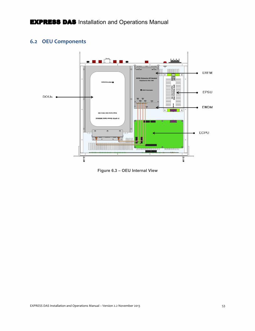
EXPRESS DAS Installation and Operations Manual
EXPRESS DAS Installation and Operations Manual – Version 2.2 November 2013 53
6.2 OEU Components
Figure 6.3 – OEU Internal View

EXPRESS DAS Installation and Operations Manual
54 EXPRESS DAS Installation and Operations Manual – Version 2.2 November 2013
Unit Name Product No. Description
Chassis
SC_OEU_C
19” rack, 2U height
EWDM
Expansion Wavelength Division Multiplexer: Converts downlink optical signals into RF signals; Converts uplink RF signals into optical signals; Compensates for optical cable loss with ODU
ECPU Expansion Central Processor Unit: Controls and monitors system status Relays status of MRU/ARU to BIU
EPSU Expansion Power Supply Unit: Input power: DC -48V, Output power: 9V, 6V
ERFM Expansion Radio Frequency Module: Regenerates downlink signals and transmit FSK modem signals. Regenerate uplink signals and receive FSK modem signals.
DOU SC_ODU OM 4
4-Port optical module (Max 2 DOUs per OEU): Converts downlink RF signals to optical signals; Converts uplink optical signals to RF signals; Provides up to four optical ports per module
Fuse Contact SOLiD support for replacement
Provides power protection for the OEU Chassis. NOTE: May require replacement after power surge or if power connections are made improperly.
Table 6.3 – OEU Components
6.2.1 OEU Components – Mechanical Specifications
Unit Name Dimension (H x W x D mm)
Weight (kg) Power Consumption (W)
OEU Chassis 482.6 (19”) x 88.1 (2U) x 450 6.1 12
4 Port Optical Module 169 x 33 x 302 1.7 each 14
Blank Card 169 x 33 x 302 0.4 -
Table 6.4 – OEU Components – Mechanical Specifications

EXPRESS DAS Installation and Operations Manual
EXPRESS DAS Installation and Operations Manual – Version 2.2 November 2013 55
6.2.2 Donor Optic Unit
Within the OEU, converting RF signals to optical signals and back again is the job of the Donor Optic
Units (DOUs). Each OEU can support up to two DOUs. Each DOU supports four optical ports, providing
connection for up to eight MRUs. The DOU used in the OEU is the same unit as found in the ODU. See
page 30 for more detail.
6.2.3 Extension Wavelength Division Multiplexer (EWDM)
The EWDM module converts the downlink signals (optical to electronic) and also the uplink signal
(electronic to optical). An FSK modem provides communication with the BIU, and an attenuation feature
can compensate for optical cable loss between ODUs. The EWDM has internal wave division multiplexing
(WDM) functionality allowing it to connect to MRUs/ARUs through a single optical cable.
6.2.4 Expansion Central Processor Unit (ECPU)
The ECPU monitors and controls the status of the modules installed in the OEU. This unit communicates
with and acts as a bridge between the BIU and MRU.
In addition, the unit has an USB-B port for connecting a PC and controlling system devices. At the front
panel, an LED indicates the communication status with the BIU and the MRUs/ARUs. It also has ALM
LED indicator to show if a device is faulty.
6.2.5 Expansion Radio Frequency Module (ERFM)
The ERFM reconstructs downlink and uplink signals that may have been degraded by the optical modules.
This module communicates with the MRU through an internal FSK modem.
6.2.6 Expansion Power Supply Unit (EPSU)
The EPSU acts as a DC/DC Converter. The unit receives -48V and delivers +9V and +6V of DC power
required for the OEU.
NOTE: The EWDM, ECPU, ERFM and EPSU are factory installed and not field replaceable. If you
suspect this unit is not operating properly, contact SOLiD support.

EXPRESS DAS Installation and Operations Manual
56 EXPRESS DAS Installation and Operations Manual – Version 2.2 November 2013
6.3 OEU Front / Rear Panel – Indicators and Connectors
Figure 6.4 – OEU Front Panel
No. Item Description
1. EWDM LED LED indicator to check EWDM status 2. DOU LED LED indicator to check DOU module status
3. System LED and Reset Communication status with devices, alarm status of the system and reset switch
4. USB (B Type) port for network management
USB port for communication and diagnosis of devices through PC/laptop.
Table 6.5 – OEU Front Panel Indicators
Figure 6.5 – OEU Rear Panel
No. Item Description
1. GND Port Terminal for system ground
2. DC Input Port Input terminal for DC -48V
3. Power switch Power ON/OFF switch 4. To/From ODU Optic Port SC/APC optical connector terminal 5. To/From MRU Optic Port SC/APC optical connector terminal; use one optical cable per MRU.
Table 6.6 – OEU Rear Panel Connectors

EXPRESS DAS Installation and Operations Manual
EXPRESS DAS Installation and Operations Manual – Version 2.2 November 2013 57
7 DAS Management System (DMS-‐600) The DMS-600 is the alarming, diagnostic, and control interface for the SOLiD EXPRESS DAS system. It
gathers system information from the DAS network –user management, inventory management, event log,
alarm management and external relays – and transmits this data via SNMP (Simple Network
Management Protocol) to a local or remote Network Operations Center (NOC) facility for monitoring. The
DMS-600 provides these functions for the DAS network:
• LAN (TCP/IP) connectivity between the DMS-600 and BIU MCPU (Main Central Processor Unit) • Graphical user interface running in web browser • Command and control for up to 20 BIUs • SNMP Traps to NOC • DAS System upgrades via Web • EasySET (Auto Commissioning) • Inventory Management • Filtering and clearing of System & Event log; Printing of Inventory and System & Event Log • Exporting of Inventory and System & Event Log to CSV • Automatic DMS system upgrades via the web (with annual maintenance package)
The figure shows the data flow between the BIU, the DMS-600 and an external NOC.
Figure 7.1 – DAS Management with DMS-600
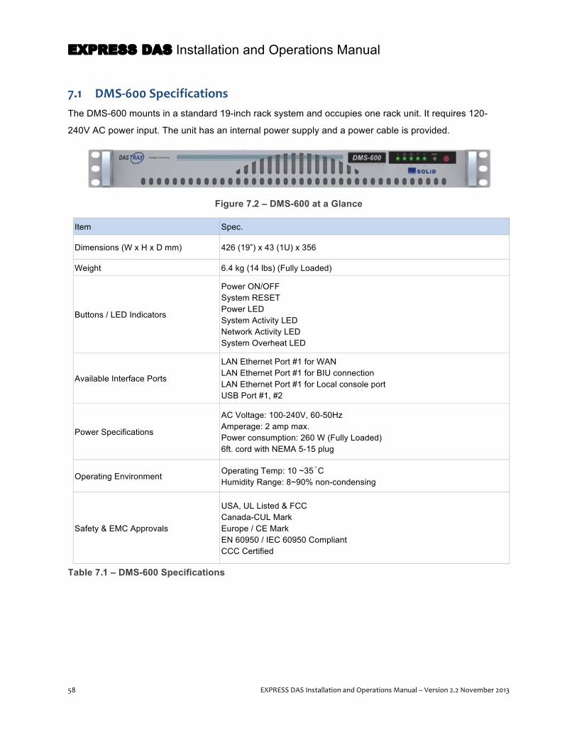
EXPRESS DAS Installation and Operations Manual
58 EXPRESS DAS Installation and Operations Manual – Version 2.2 November 2013
7.1 DMS-‐600 Specifications The DMS-600 mounts in a standard 19-inch rack system and occupies one rack unit. It requires 120-
240V AC power input. The unit has an internal power supply and a power cable is provided.
Figure 7.2 – DMS-600 at a Glance
Item Spec.
Dimensions (W x H x D mm) 426 (19”) x 43 (1U) x 356
Weight 6.4 kg (14 lbs) (Fully Loaded)
Buttons / LED Indicators
Power ON/OFF System RESET Power LED System Activity LED Network Activity LED System Overheat LED
Available Interface Ports
LAN Ethernet Port #1 for WAN LAN Ethernet Port #1 for BIU connection LAN Ethernet Port #1 for Local console port USB Port #1, #2
Power Specifications
AC Voltage: 100-240V, 60-50Hz Amperage: 2 amp max. Power consumption: 260 W (Fully Loaded) 6ft. cord with NEMA 5-15 plug
Operating Environment Operating Temp: 10 ~35˚C Humidity Range: 8~90% non-condensing
Safety & EMC Approvals
USA, UL Listed & FCC Canada-CUL Mark Europe / CE Mark EN 60950 / IEC 60950 Compliant CCC Certified
Table 7.1 – DMS-600 Specifications
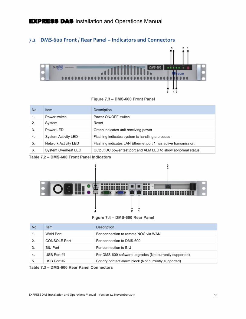
EXPRESS DAS Installation and Operations Manual
EXPRESS DAS Installation and Operations Manual – Version 2.2 November 2013 59
7.2 DMS-‐600 Front / Rear Panel – Indicators and Connectors
Figure 7.3 – DMS-600 Front Panel
No. Item Description
1. Power switch Power ON/OFF switch
2. System Reset
3. Power LED Green indicates unit receiving power
4. System Activity LED Flashing indicates system is handling a process
5. Network Activity LED Flashing indicates LAN Ethernet port 1 has active transmission.
6. System Overheat LED Output DC power test port and ALM LED to show abnormal status
Table 7.2 – DMS-600 Front Panel Indicators
Figure 7.4 – DMS-600 Rear Panel
No. Item Description
1. WAN Port For connection to remote NOC via WAN
2. CONSOLE Port For connection to DMS-600
3. BIU Port For connection to BIU
4. USB Port #1 For DMS-600 software upgrades (Not currently supported)
5. USB Port #2 For dry contact alarm block (Not currently supported)
Table 7.3 – DMS-600 Rear Panel Connectors
EXPRESS DAS Installation and Operations Manual
60 EXPRESS DAS Installation and Operations Manual – Version 2.2 November 2013
8 Installation – Headend Equipment: BIU, Power Supply, ODU, DMS-‐600
This chapter explains how to install and connect the DAS equipment that comprises the system’s
headend:
• The Base-Station Interface Unit (BIU) • The DC power supply • The interface to the RF Source (BTS or BDA) • The Optical Drive Unit(s) (ODUs) • The DAS Management System (DMS-600)
SOLiD technicians configure and label the equipment at the SOLiD facility prior to shipping. Note labeling
on all equipment. Remove each item from its packaging and inspect the hardware. Contact SOLiD
Support if the product is damaged.
8.1 Before you Begin Headend components are typically installed in a standard 19-inch rack according to these guidelines:
• The BIU requires 5U of rack space and must have 1U of free space above and below to circulate air and dissipate heat.
• The DC Power Supply requires 1U of space. It typically mounts below the BIU. • The ODU components require 1U of space and can be stacked directly above one another. The
ODU(s) mount above the BIU in the rack. • The DMS-600 requires 1U of space but should have 1U of space above and below. The DMS-
600 typically mounts above the ODU(s).

EXPRESS DAS Installation and Operations Manual
EXPRESS DAS Installation and Operations Manual – Version 2.2 November 2013 61
Before you begin this part of the installation process, make sure you have the following items. Those
items marked with an “O” ship with the unit. The installer will supply items marked with an “X.”
Unit Item / Action Accessories Tools Required Status
BIU
Chassis rack mounting M6 Screw (4 EA) No.0 Screw driver (+) X
Ground connection AWG #10-12 cable No.0 Screw driver (+) Lug crimper
X
RF cable connection to Base Station
RF SMA-P cable Spanner (8mm) X
Power Shelf Mounting M6 Screws (4 EA) No.0 Screw driver (+) X
Power cable connection DC -48V power cable (1 Pair) [AWG #12, 2 meter, with 4.5 ø square lugs at both ends]
No.0 Screw driver (+) O
ODU
Chassis rack mounting M6 Screws (4 EA) No.0 Screw driver (+) X
Ground connection
M4 Screw (Electric Current/ 1EA)
No.0 Screw driver (+) X
AWG #10~1 2 Cable No.0 Screw driver (+) Lug crimper
X
Connection to ROU or OEU Optic SC/APC cable (1 per ROU)
X
Connecting with BIU
Power Cable (1EA) [700 millimeter, with D-SUB 15PIN(MALE/to BIU) connector at one end, D-SUB 15PIN (FEMALE/to ODU) connector at another end]
O
Connection with BIU Connection with ROU or OEU
RF Cable (2EA) [SS405 White, 670 millimeter, with SMA-SP (MALE) connector at both ends]
Spanner (8mm) Torque: 8~12kgf.cm
O
Optic SC/APC Cable - X
DMS
DMS-1200 rack mounting M6 Screws (4 EA) No.0 Screw driver (+) X
WAN port connection Straight type LAN cable (1EA) X
BIU port connection Straight type 2m LAN cable (1EA)
O
Connection to power supply AC 110-220V Power Cable O
Table 8.1 – Tools and Accessories for Installing Headend Equipment

EXPRESS DAS Installation and Operations Manual
62 EXPRESS DAS Installation and Operations Manual – Version 2.2 November 2013
8.2 Install BIU Chassis Typically, the BIU will be installed in a 19-inch equipment rack. The BIU occupies 5U of rack space.
1- When positioning the BIU in the rack, make sure to leave 1U of space between the BIU and other units
for air circulation. The power shelf typically mounts below the BIU. The ODUs and DMS-600 mount above.
2- Position the BIU in the rack holding the unit by the shift handles. Insert the M6 bolts in the mounting
holes and tighten the screws to secure the chassis.
Figure 8.1 – BIU Rack Installation
8.3 Install DC Power Shelf and Connect to BIU 1- Install the DC Power Shelf in the 19-inch rack below the BIU leaving 1U of space.
2- Before connecting the power supply to the terminal block at the back of the BIU, check the voltage
coming from the power supply using a voltage meter. Connect the positive "+" terminal of the volt meter
with the ground “GND” terminal and then connect the negative "–" terminal of the meter with the -48V
terminal. The power source should be providing -48Vdc voltage.
3- After verifying the power source, connect the DC power cable to the BIU terminal block. Connect the
blue cable to the -48v terminal. Connect the black cable to the GND terminal as shown in the following
figure.

EXPRESS DAS Installation and Operations Manual
EXPRESS DAS Installation and Operations Manual – Version 2.2 November 2013 63
Figure 8.2 – BIU Terminal Block
If you connect the power system to the BIU with the incorrect polarity (reversing the "+" terminal
and the "–" terminal connections), the unit will not operate.
4- After connecting the power supply unit, power it on using the ON/OFF switch found on the faceplate of
the Main Power Supply Unit (MPSU) in the BIU. A green LED indicates power to the unit as shown in the
next figure.
Figure 8.3 – MPSU LED Indicators

EXPRESS DAS Installation and Operations Manual
64 EXPRESS DAS Installation and Operations Manual – Version 2.2 November 2013
5- Once you have verified the unit is receiving power, turn off power to the BIU. You can power on the
system once you have connected the BTS or other RF source as described in the next sections.
8.3.1 BIU Power Consumption
The power supply provided for the BIU has factored in the max load for the system, but for your
information, the table below shows power consumption of the BIU. Keep in mind that the BIU also
supplies power to the ODU(s). Power consumption data for the ODU(s) are provided on page 74.
Part Unit Name Manufacturer Product No.
Power Consumption (W)
SC_BIU_SISO Common Part
Chassis SC_BIU_C -
7.2W MCPU SC_MCPU 4.8w
MPSU SC_MPSU -
MCDU SC_MCDU 2.4W
SC_BIU_MIMO Common Part
Chassis SC_BIU_Chassis -
9.6W MCPU SC_MCPU 4.8W
MPSU SC_MPSU -
MCDU SC_MCDU 4.8W
MDBU
850C+1900P SC_MDBU_850_1900 16W
700LTE+AWS SC_MDBU_700LTE_2100 16W
1900P SC_MDBU_1900 9W
800i+900i SC_MDBU_800_900 16W
Table 8.2 – BIU Power Consumption

EXPRESS DAS Installation and Operations Manual
EXPRESS DAS Installation and Operations Manual – Version 2.2 November 2013 65
8.3.2 Installing Additional MDBUs
The BIU chassis comes equipped with the correct type and number of MDBU(s) based on the
configuration you ordered, and blank cards come pre-installed in unused MDBU slots. Unused ports are
terminated with termination loads when the BIU is configured at the SOLiD facility.
You can expand or upgrade the DAS system at any time by installing additional MDBUs or removing
existing units. The BIU accepts up to four MDBUs, and these units can be inserted in any slot. Make sure
to fill unused MDBU slots with blank cards and to terminate unused ports.
1- Remove the front bar on the BIU chassis using a Phillips screw driver (+).
2- Slide the MDBU into the slot aligning the upper and lower guide rail and then lock the ejector up.
3- Install blank cards in any unused slots.
4- Install the front bar back to its original position after completing installation.
Figure 8.4 – MDBU Installation
Front Bar
Front Bar
Guide Rail MDBU Unit
Blank Unit
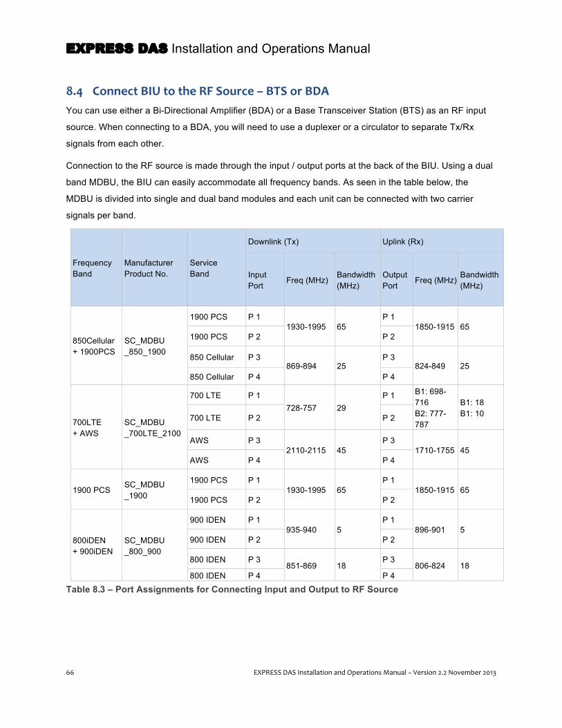
EXPRESS DAS Installation and Operations Manual
66 EXPRESS DAS Installation and Operations Manual – Version 2.2 November 2013
8.4 Connect BIU to the RF Source – BTS or BDA You can use either a Bi-Directional Amplifier (BDA) or a Base Transceiver Station (BTS) as an RF input
source. When connecting to a BDA, you will need to use a duplexer or a circulator to separate Tx/Rx
signals from each other.
Connection to the RF source is made through the input / output ports at the back of the BIU. Using a dual
band MDBU, the BIU can easily accommodate all frequency bands. As seen in the table below, the
MDBU is divided into single and dual band modules and each unit can be connected with two carrier
signals per band.
Frequency Band
Manufacturer Product No.
Service Band
Downlink (Tx) Uplink (Rx)
Input Port
Freq (MHz) Bandwidth (MHz)
Output Port
Freq (MHz) Bandwidth (MHz)
850Cellular + 1900PCS
SC_MDBU _850_1900
1900 PCS P 1 1930-1995 65
P 1 1850-1915 65
1900 PCS P 2 P 2
850 Cellular P 3 869-894 25
P 3 824-849 25
850 Cellular P 4 P 4
700LTE + AWS
SC_MDBU _700LTE_2100
700 LTE P 1 728-757 29
P 1 B1: 698-716 B2: 777-787
B1: 18 B1: 10 700 LTE P 2 P 2
AWS P 3 2110-2115 45
P 3 1710-1755 45
AWS P 4 P 4
1900 PCS SC_MDBU _1900
1900 PCS P 1 1930-1995 65
P 1 1850-1915 65
1900 PCS P 2 P 2
800iDEN + 900iDEN
SC_MDBU _800_900
900 IDEN P 1 935-940 5
P 1 896-901 5
900 IDEN P 2 P 2
800 IDEN P 3 851-869 18
P 3 806-824 18
800 IDEN P 4 P 4
Table 8.3 – Port Assignments for Connecting Input and Output to RF Source

EXPRESS DAS Installation and Operations Manual
EXPRESS DAS Installation and Operations Manual – Version 2.2 November 2013 67
At the rear of BIU, you will find the Tx input and Rx output ports for each MDBU as shown in the following
figure. For each port, Tx and Rx signals are separated from each other and labeled as "#1, #2, #3 and
#4." Refer to the table above to ensure proper connection for the input and output ports of the
corresponding MDBU. It is not necessary to terminate unused ports on the BIU backplane.
Figure 8.5 – BIU RF interface diagram
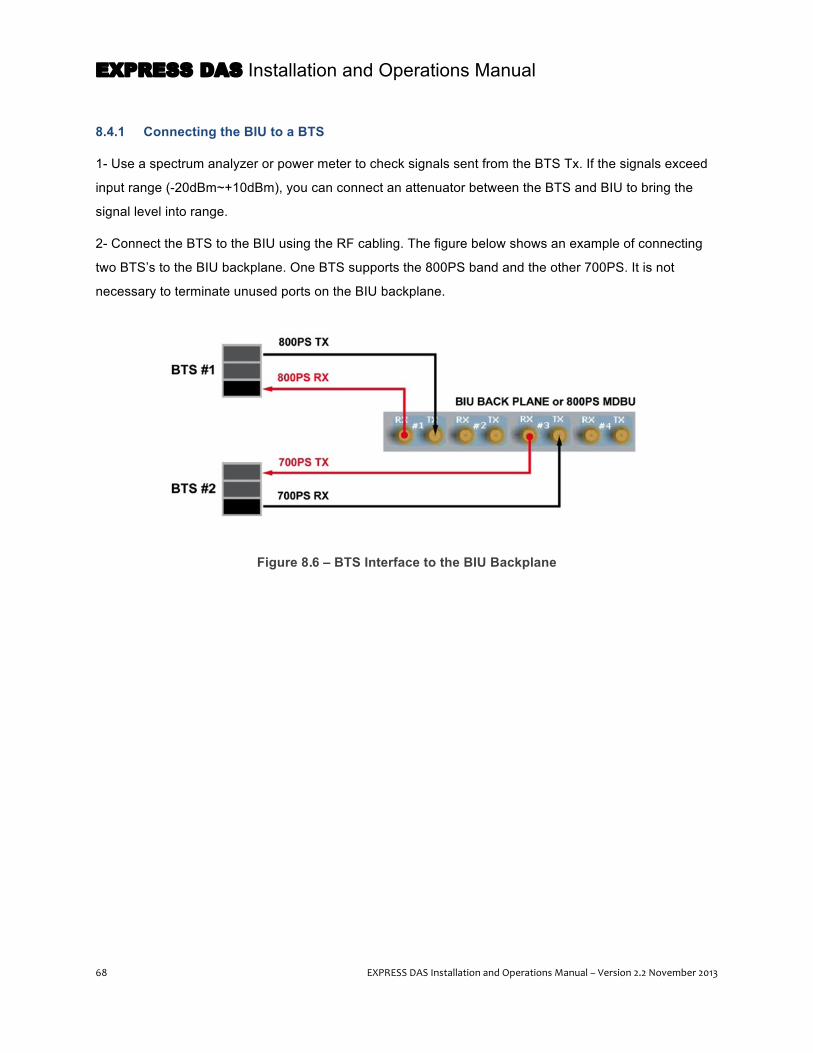
EXPRESS DAS Installation and Operations Manual
68 EXPRESS DAS Installation and Operations Manual – Version 2.2 November 2013
8.4.1 Connecting the BIU to a BTS
1- Use a spectrum analyzer or power meter to check signals sent from the BTS Tx. If the signals exceed
input range (-20dBm~+10dBm), you can connect an attenuator between the BTS and BIU to bring the
signal level into range.
2- Connect the BTS to the BIU using the RF cabling. The figure below shows an example of connecting
two BTS’s to the BIU backplane. One BTS supports the 800PS band and the other 700PS. It is not
necessary to terminate unused ports on the BIU backplane.
Figure 8.6 – BTS Interface to the BIU Backplane
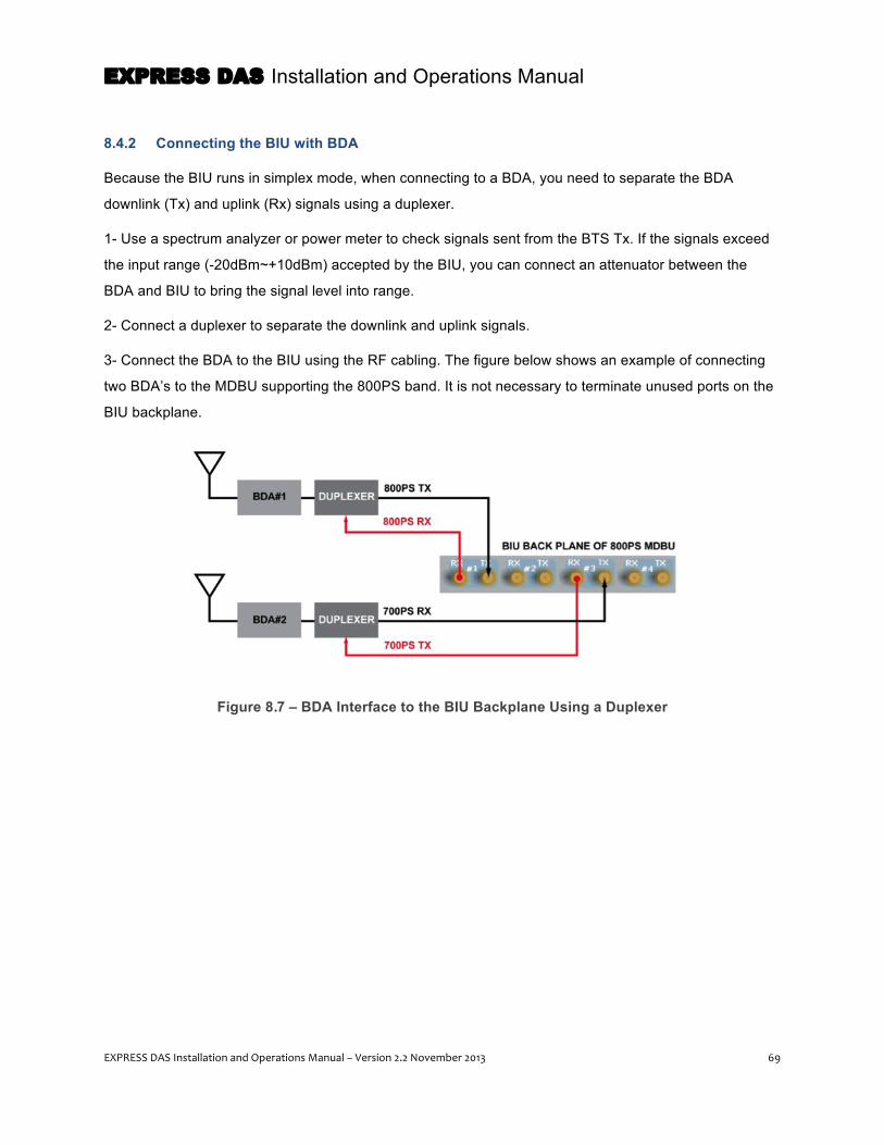
EXPRESS DAS Installation and Operations Manual
EXPRESS DAS Installation and Operations Manual – Version 2.2 November 2013 69
8.4.2 Connecting the BIU with BDA
Because the BIU runs in simplex mode, when connecting to a BDA, you need to separate the BDA
downlink (Tx) and uplink (Rx) signals using a duplexer.
1- Use a spectrum analyzer or power meter to check signals sent from the BTS Tx. If the signals exceed
the input range (-20dBm~+10dBm) accepted by the BIU, you can connect an attenuator between the
BDA and BIU to bring the signal level into range.
2- Connect a duplexer to separate the downlink and uplink signals.
3- Connect the BDA to the BIU using the RF cabling. The figure below shows an example of connecting
two BDA’s to the MDBU supporting the 800PS band. It is not necessary to terminate unused ports on the
BIU backplane.
Figure 8.7 – BDA Interface to the BIU Backplane Using a Duplexer
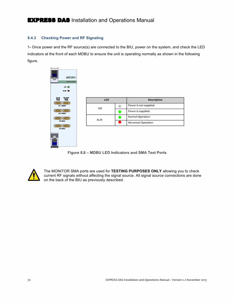
EXPRESS DAS Installation and Operations Manual
70 EXPRESS DAS Installation and Operations Manual – Version 2.2 November 2013
8.4.3 Checking Power and RF Signaling
1- Once power and the RF source(s) are connected to the BIU, power on the system, and check the LED
indicators at the front of each MDBU to ensure the unit is operating normally as shown in the following
figure.
Figure 8.8 – MDBU LED Indicators and SMA Test Ports
The MONITOR SMA ports are used for TESTING PURPOSES ONLY allowing you to check current RF signals without affecting the signal source. All signal source connections are done on the back of the BIU as previously described.

EXPRESS DAS Installation and Operations Manual
EXPRESS DAS Installation and Operations Manual – Version 2.2 November 2013 71
8.5 Install Optical Drive Units (ODUs) The ODU is designed for a standard 19-inch equipment rack and occupies 1U of rack space. The BIU
supports up to four ODUs, depending on the system’s requirements. The ODU(s) should be installed
above the BIU.
1- When positioning the ODU(s) in the rack, make sure to leave 1U of space between the BIU and first
ODU. This gap provides air circulation to help dissipate heat from the BIU. Multiple ODUs (up to four) can
be stacked in the rack, but do not require gaps between each unit as shown in the next figure.
2- Position the ODU(s) in the rack. Insert the M6 bolts in the mounting holes and tighten the screws to
secure the unit(s).
Figure 8.9 – ODU Rack Installation
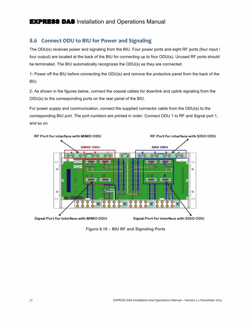
EXPRESS DAS Installation and Operations Manual
72 EXPRESS DAS Installation and Operations Manual – Version 2.2 November 2013
8.6 Connect ODU to BIU for Power and Signaling The ODU(s) receives power and signaling from the BIU. Four power ports and eight RF ports (four input /
four output) are located at the back of the BIU for connecting up to four ODU(s). Unused RF ports should
be terminated. The BIU automatically recognizes the ODU(s) as they are connected.
1- Power off the BIU before connecting the ODU(s) and remove the protective panel from the back of the
BIU.
2- As shown in the figures below, connect the coaxial cables for downlink and uplink signaling from the
ODU(s) to the corresponding ports on the rear panel of the BIU.
For power supply and communication, connect the supplied connector cable from the ODU(s) to the
corresponding BIU port. The port numbers are printed in order. Connect ODU 1 to RF and Signal port 1,
and so on.
Figure 8.10 – BIU RF and Signaling Ports

EXPRESS DAS Installation and Operations Manual
EXPRESS DAS Installation and Operations Manual – Version 2.2 November 2013 73
Figure 8.11 – Connecting the BIU to ODU(s)
Take care to connect the ODU(s) in the correct order and to distinguish between MIMO and SISO units. Otherwise, related devices may fail to communicate with each other or the unit may read wrong information. For unused RF Ports in an ODU expansion, make sure to terminate them using SMA terminators.
3- Once all cabling is in place, re-attach the protective panel at the back of the BIU.
4- Power on the BIU. Check the LEDs at the front of the BIU to ensure the connection with the ODU(s) is
functioning correctly.
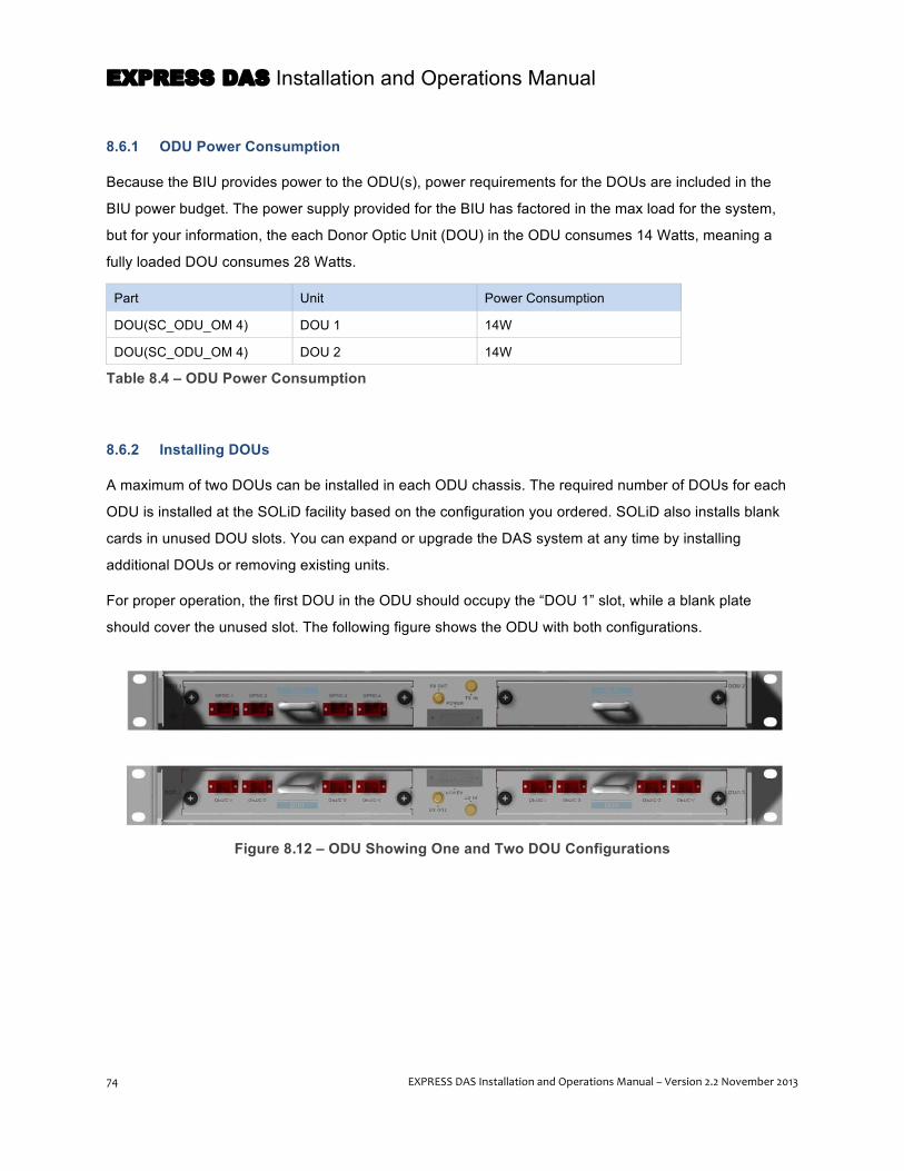
EXPRESS DAS Installation and Operations Manual
74 EXPRESS DAS Installation and Operations Manual – Version 2.2 November 2013
8.6.1 ODU Power Consumption
Because the BIU provides power to the ODU(s), power requirements for the DOUs are included in the
BIU power budget. The power supply provided for the BIU has factored in the max load for the system,
but for your information, the each Donor Optic Unit (DOU) in the ODU consumes 14 Watts, meaning a
fully loaded DOU consumes 28 Watts.
Part Unit Power Consumption
DOU(SC_ODU_OM 4) DOU 1 14W
DOU(SC_ODU_OM 4) DOU 2 14W
Table 8.4 – ODU Power Consumption
8.6.2 Installing DOUs
A maximum of two DOUs can be installed in each ODU chassis. The required number of DOUs for each
ODU is installed at the SOLiD facility based on the configuration you ordered. SOLiD also installs blank
cards in unused DOU slots. You can expand or upgrade the DAS system at any time by installing
additional DOUs or removing existing units.
For proper operation, the first DOU in the ODU should occupy the “DOU 1” slot, while a blank plate
should cover the unused slot. The following figure shows the ODU with both configurations.
Figure 8.12 – ODU Showing One and Two DOU Configurations

EXPRESS DAS Installation and Operations Manual
EXPRESS DAS Installation and Operations Manual – Version 2.2 November 2013 75
8.6.3 Connecting ODU Optic Cabling
Each optical port on the DOUs can connect to an MRU using a single fiber optic cable with SC/APC
connectors. When connecting to an optional OEU, optical port 4 must be used from either DOU in ODU 1
or 2. ODU 3 and 4 cannot be used for connection to the OEU.
Figure 8.13 – SC/APC Fiber Terminations
1- Connect the fiber optic cable to the port(s) on the DOU(s).
8.7 Installing the DMS-‐600 The DAS Management System (DMS-600) fits in a standard 19-inch equipment rack and occupies 1U of
rack space. The unit has an internal power supply and requires standard 120-240V AC power.
1- Position the DMS-600 in the rack, making sure to leave 1U of space between the DMS-600 and the
uppermost ODU. This gap provides air circulation to help dissipate heat from the equipment.
2- Insert the M6 screws in the mounting holes and tighten the screws to secure the unit.
3- Connect the DMS-600 to the Ethernet port on the BIU using the supplied cable. Connect the unit to a
power source (typically a wall socket) using the supplied power cable.
4- Power on the DMS-600.
NOTE: When purchasing, installing and maintaining the optic cables, make sure to follow the
manufacturer’s guidelines. Keep the fiber ends capped when not connected to prevent damage to the
fiber center pins. If fiber connectors seem dirty, you can clean them with alcohol.
EXPRESS DAS Installation and Operations Manual
76 EXPRESS DAS Installation and Operations Manual – Version 2.2 November 2013
9 Installation – OEU The Optical Expansion Unit (OEU) is an optional component used for extending the EXPRESS DAS to
remote locations in a campus environment. Each OEU can be equipped with a maximum of two DOUs,
allowing the DAS to support an additional eight MRUs.
SOLiD technicians configure and label the equipment at the SOLiD facility prior to shipping. Note labeling
on all equipment. Remove each item from its packaging and inspect the hardware. Contact SOLiD
Support if the product is damaged.
9.1 Before you Begin Before you begin this part of the installation process, make sure you have the following items. Those
items marked with an “O” ship with the unit. The installer will supply items marked with an “X.”
Item Accessories Tools Status
Chassis rack mounting M6 Screws (4 EA) No.0 Screw driver (+) X
Ground connection M4 Screw (Electric Current/ 1EA) No.0 Screw driver (+) X
AWG #10~1 2 Cable No.0 Screw driver (+) Lug crimper
X
Connection with ODUs/ MRUs Optic cable [SC/APC Type] X
Power cable connection DC -48V power cable (1 Pair) [AWG #12, 2 meter, with 4.5 ø square lugs at both ends]
No.0 Screw driver (+) O
Table 9.1 – Accessories and Tools List for OEU Installation

EXPRESS DAS Installation and Operations Manual
EXPRESS DAS Installation and Operations Manual – Version 2.2 November 2013 77
9.2 Install OEU Chassis The OEU is typically installed in an equipment closet. The unit is designed to mount in a standard 19-inch
rack and occupy 2U in height. The OEU requires a separate DC power unit, which should be mounted
below the OEU.
1- When positioning the OEU in the rack, make sure to allow for 1U of space below the unit to install the
DC power supply.
2- Position the OEU in the rack. Insert the M6 screws in the mounting holes and tighten the screws to
secure the unit.
9.3 Install DC Power Shelf and Connect to OEU 1- Install the DC Power Shelf in the 19-inch rack below the OEU leaving 1U of space.
2- Before connecting the power supply to the terminal block at the back of the OEU, check the voltage
coming from the power supply using a voltage meter. Connect the positive "+" terminal of the volt meter
with the ground “GND” terminal and then connect the negative "–" terminal of the meter with the -48V
terminal. The power source should be providing -48Vdc voltage.
3- After verifying the power source, connect the DC power cable to the OEU terminal block. Connect the
blue cable to the -48v terminal. Connect the black cable to the GND terminal as shown in the following
figure.
Figure 9.1 – OEU Terminal Block
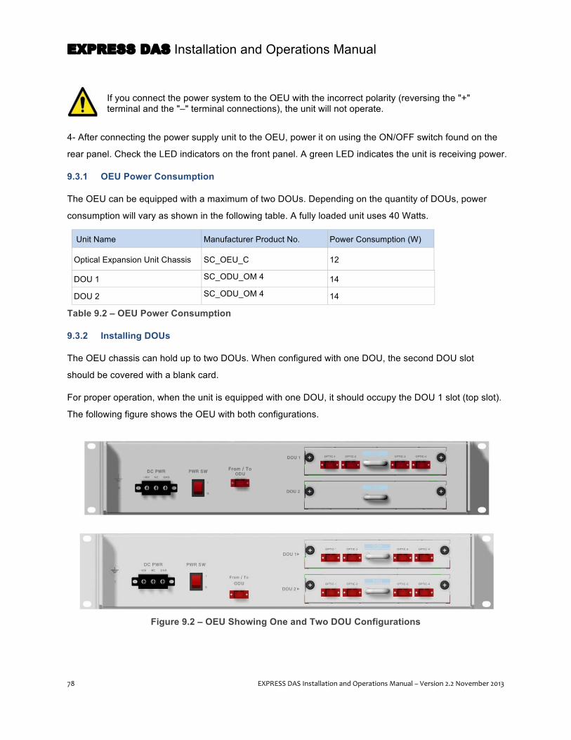
EXPRESS DAS Installation and Operations Manual
78 EXPRESS DAS Installation and Operations Manual – Version 2.2 November 2013
If you connect the power system to the OEU with the incorrect polarity (reversing the "+" terminal and the "–" terminal connections), the unit will not operate.
4- After connecting the power supply unit to the OEU, power it on using the ON/OFF switch found on the
rear panel. Check the LED indicators on the front panel. A green LED indicates the unit is receiving power.
9.3.1 OEU Power Consumption
The OEU can be equipped with a maximum of two DOUs. Depending on the quantity of DOUs, power
consumption will vary as shown in the following table. A fully loaded unit uses 40 Watts.
Unit Name Manufacturer Product No. Power Consumption (W)
Optical Expansion Unit Chassis SC_OEU_C 12
DOU 1 SC_ODU_OM 4 14
DOU 2 SC_ODU_OM 4 14
Table 9.2 – OEU Power Consumption
9.3.2 Installing DOUs
The OEU chassis can hold up to two DOUs. When configured with one DOU, the second DOU slot
should be covered with a blank card.
For proper operation, when the unit is equipped with one DOU, it should occupy the DOU 1 slot (top slot).
The following figure shows the OEU with both configurations.
Figure 9.2 – OEU Showing One and Two DOU Configurations

EXPRESS DAS Installation and Operations Manual
EXPRESS DAS Installation and Operations Manual – Version 2.2 November 2013 79
9.4 Connecting the OEU to ODU(s)
The OEU connects to the ODU using SC/APC fiber cabling. Make sure to keep the fiber ends capped
when not connected to the equipment to prevent damage to the fiber center pins. If fiber connectors seem
dirty, you can clean them using alcohol.
1- Using the fiber optic cable, connect the OEU to the fourth optical port in the ODU optical module.
If you connect the OEU to ports 1 thru 3, it will not communicate with the BIU.
Figure 9.3 – Connecting the OEU to ODU

EXPRESS DAS Installation and Operations Manual
80 EXPRESS DAS Installation and Operations Manual – Version 2.2 November 2013
10 Installation – MRU and ARU This chapter explains how to install the Main Remote Unit(s) (MRUs) and Add-on Remote Unit(s) (ARUs),
and how to connect these units to the ODU(s) at the headend.
SOLiD technicians configure and label the equipment at the SOLiD facility prior to shipping. Note labeling
on all equipment. Remove each item from its packaging and inspect the hardware. Contact SOLiD
Support if the product is damaged.
10.1 Before you Begin The MRU/ARU enclosures have two options: one is meant for indoor use, while the other is designed for
outdoor installations and meets NEMA 4 standards to protect from water and dirt intrusion. The
enclosures can be wall mounted, either side by side or stacked; they can also be installed in a standard
19” rack, either vertically or horizontally, using special mounting frames.
Before you begin this part of the installation process, make sure you have the following items. Those
items marked with an “O” ship with the unit. The installer will supply items marked with an “X.”
Installation Item Accessories Tools Status
Wall mounting on brackets
M8 Bolts (Note: Wall mount brackets included for both MRU and ARU. All other mounting brackets are optional and available from SOLiD.)
Spanner (13mm) X
MRU/ARU Mounting (wall brackets or rack)
M6 Wrench Bolts Hexagon Wrench O
Connecting Power AC 120V power cable (1) or DC -48V power cable (1 Pair)
O
Grounding Unit Ground cable with terminal lugs [Max. AWG #12]
No.0 Screw driver (+) Lug crimper
X
Connecting Fiber Optic to ODU (MRU only)
Optic cable [SC/APC Type] Spanner (32mm) X
Connecting to Antenna (MRU only)
RF cable [N-type Male ] (1) Spanner (20mm) Connector crimper
X
Communication between MRU and ARU
Communication cable (1) and SMA cable (3) O
Table 10.1 – Tools and Accessories for Installing MRUs/ARUs
NOTE: For instructions on installing the VHF/UHF Add on Remote (AOR) see page 95.
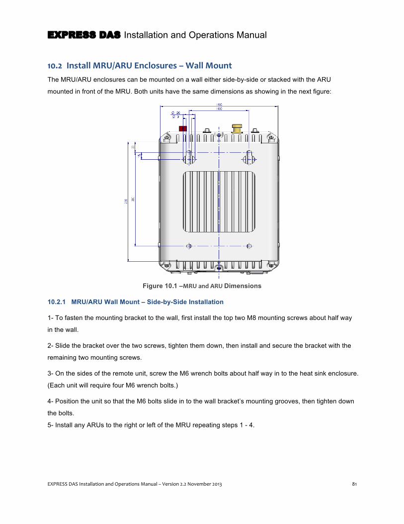
EXPRESS DAS Installation and Operations Manual
EXPRESS DAS Installation and Operations Manual – Version 2.2 November 2013 81
10.2 Install MRU/ARU Enclosures – Wall Mount The MRU/ARU enclosures can be mounted on a wall either side-by-side or stacked with the ARU
mounted in front of the MRU. Both units have the same dimensions as showing in the next figure:
Figure 10.1 –MRU and ARU Dimensions
10.2.1 MRU/ARU Wall Mount – Side-by-Side Installation
1- To fasten the mounting bracket to the wall, first install the top two M8 mounting screws about half way
in the wall.
2- Slide the bracket over the two screws, tighten them down, then install and secure the bracket with the
remaining two mounting screws.
3- On the sides of the remote unit, screw the M6 wrench bolts about half way in to the heat sink enclosure.
(Each unit will require four M6 wrench bolts.)
4- Position the unit so that the M6 bolts slide in to the wall bracket’s mounting grooves, then tighten down
the bolts.
5- Install any ARUs to the right or left of the MRU repeating steps 1 - 4.

EXPRESS DAS Installation and Operations Manual
82 EXPRESS DAS Installation and Operations Manual – Version 2.2 November 2013
Figure 10.2 – Side-by-Side Wall Mount Installation for the MRU / ARU
2-‐M8 FIXING SCREW
2-‐M8 FIXING SCREW
F

EXPRESS DAS Installation and Operations Manual
EXPRESS DAS Installation and Operations Manual – Version 2.2 November 2013 83
10.2.2 MRU/ARU Wall Mount – Stacked Installation
If space prohibits the MRU and ARU from being mounted side by side, the units can be installed in a
stacked configuration. Stacking the units requires a special bracket (part number SC-ARU-STK), which is
available from SOLiD.
The next figure shows the dimension of the bracket used for stack mounting.
Figure 10.3 – Dimensions of Stacking Bracket

EXPRESS DAS Installation and Operations Manual
84 EXPRESS DAS Installation and Operations Manual – Version 2.2 November 2013
1- Using the instructions above, first install the MRU on the wall.
2- Install the bracket for stacked installation over the MRU.
3- Finally install the ARU on the bracket.
Figure 10.4 – Stack Mounting the MRU/ARU
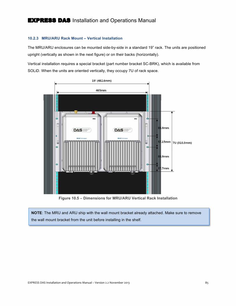
EXPRESS DAS Installation and Operations Manual
EXPRESS DAS Installation and Operations Manual – Version 2.2 November 2013 85
10.2.3 MRU/ARU Rack Mount – Vertical Installation
The MRU/ARU enclosures can be mounted side-by-side in a standard 19” rack. The units are positioned
upright (vertically as shown in the next figure) or on their backs (horizontally).
Vertical installation requires a special bracket (part number bracket SC-BRK), which is available from
SOLiD. When the units are oriented vertically, they occupy 7U of rack space.
Figure 10.5 – Dimensions for MRU/ARU Vertical Rack Installation
NOTE: The MRU and ARU ship with the wall mount bracket already attached. Make sure to remove
the wall mount bracket from the unit before installing in the shelf.
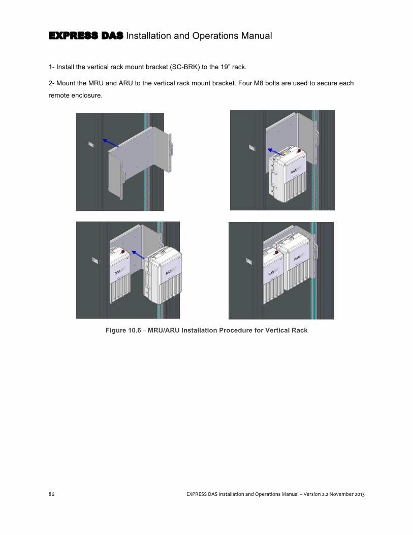
EXPRESS DAS Installation and Operations Manual
86 EXPRESS DAS Installation and Operations Manual – Version 2.2 November 2013
1- Install the vertical rack mount bracket (SC-BRK) to the 19” rack.
2- Mount the MRU and ARU to the vertical rack mount bracket. Four M8 bolts are used to secure each
remote enclosure.
Figure 10.6 – MRU/ARU Installation Procedure for Vertical Rack

EXPRESS DAS Installation and Operations Manual
EXPRESS DAS Installation and Operations Manual – Version 2.2 November 2013 87
10.2.4 MRU/ARU Rack Mount – Horizontal Installation
Likewise, for installing the enclosures horizontally, a specific bracket is required (part number SC-RM19)
which is available from SOLiD. When mounted horizontally (as shown in the next figure), each unit
occupies 4U of rack space.
Figure 10.7 – Dimensions for MRU/ARU Horizontal Rack Installation
1- Install the horizontal mounting bracket in the rack.
2- Open the front cover of horizontal bracket.
3- Slide in the MRU and ARU.
4- Finally, close the front cover of the horizontal bracket after completing cable connection and enclosure
grounding.
NOTE: The MRU and ARU ship with the wall mount bracket already attached. Make sure to remove
the wall mount bracket from the unit before installing in the shelf.

EXPRESS DAS Installation and Operations Manual
88 EXPRESS DAS Installation and Operations Manual – Version 2.2 November 2013
Figure 10.8 – MRU/ARU Installation Procedure for Horizontal Rack
10.3 Connect MRU / ARU Power The MRU and ARU support both DC-48V and AC120V for input power. Make sure to order the
appropriate power unit according to your installation requirements. Based on your configuration, SOLiD
will ship the correct power supply unit already installed and provide the correct power cable with the
proper connector attached.
Figure 10.9 – MRU / ARU Power Ports – AC/DC and DC/DC
NOTE: The MRU / ARU do not have an ON/OFF power switch. Power is supplied to the units when
the power cord is plugged into the AC source.

EXPRESS DAS Installation and Operations Manual
EXPRESS DAS Installation and Operations Manual – Version 2.2 November 2013 89
10.3.1 MRU/ARU Power Consumption
The following table shows power consumption for the MRU and ARU.
Part Unit Name Manufacturer Product No. Power Consumption (W)
MRU
1900MHz Main Remote Unit
MRU_AC_1900
45W MRU_AC_NEMA_1900
MRU_DC_1900
MRU_DC_NEMA_1900
850MHz & 1900MHz Main Remote Unit
MRU_AC_850_1900
50W MRU_AC_NEMA_850_1900
MRU_DC_850_1900
MRU_DC_NEMA_850_1900
ARU
700MHz LTE & 2100MHz Add-on Remote Unit
ARU_AC_700LTE_2100
40W ARU_AC_NEMA_700LTE_2100
ARU_DC_700LTE_2100
ARU_DC_700LTE_NEMA_2100
800MHz & 900MHz Add-on Remote Unit
ARU_AC_800_900
44W ARU_AC_NEMA_800_900
ARU_DC_800_900
ARU_DC_NEMA_800_900
Table 10.2 – MRU/ARU Power Consumption

EXPRESS DAS Installation and Operations Manual
90 EXPRESS DAS Installation and Operations Manual – Version 2.2 November 2013
10.4 Connect Ground Terminal The MRU and ARU each have one ground terminal port at the bottom of the unit. The ground lug is
designed meeting the SQ5.5 standard.
Figure 10.10 – MRU / ARU Ground Terminal
1- Take off the GND terminal port from the enclosure and connect to the ground cable. Then reconnect it
to the enclosure.
2- Connect the opposite end of the ground cable to the communication GND of the building.

EXPRESS DAS Installation and Operations Manual
EXPRESS DAS Installation and Operations Manual – Version 2.2 November 2013 91
10.5 Connect Optical Cabling The MRU(s) connect to the optic modules in the headend ODU(s) (or optional OEUs) using fiber optic
cables with SC/APC connectors. SOLiD does not provide fiber optic cables with the DAS equipment. Only
the MRU has optical port; there is no optical port on the ARU.
When purchasing, installing and maintaining the optic cables, make sure to follow the manufacturer’s
guidelines. To prevent the fiber interface, make sure to keep it covered until connecting the fiber strand.
Keep the fiber ends capped when not connected to the equipment to prevent damage to the fiber center
pins. If fiber connectors collect dirt, you can clean using alcohol.
1- Insert the fiber into the optical port of the MRU. The bend radius of the fiber should not be less than
least 5 inches to minimize insertion loss and avoid damage to the optic cable.
During software commissioning, you will check to ensure the PD value of the optic module is within
acceptable range (+4--1dBm).
Figure 10.11 – Attaching Fiber Optic Cabling to the MRU

EXPRESS DAS Installation and Operations Manual
92 EXPRESS DAS Installation and Operations Manual – Version 2.2 November 2013
10.6 Connect MRU and ARU The downlink/uplink signals for the Add-on Remote Units receive/transmit through RF ports of the MRU,
so you will need to connect the units through the external port to enable this communication.
1- Make all connections between the units according to the following figure and table. Make sure to
observe recommended torque values. Items marked with an “O” ship with the unit. The installer should
provide items marked “X.”
Figure 10.12 – Connecting the MRU to the ARU

EXPRESS DAS Installation and Operations Manual
EXPRESS DAS Installation and Operations Manual – Version 2.2 November 2013 93
No. Item Type Tool Status
1 TRX CABLE 1 RF Interface Cable (SMA Male) (Qty: 1) Spanner (8mm) Torque 8~12kgf.cm
O
2 TRX CABLE 2 RF Interface Cable (SMA Male) (Qty: 1) Spanner (8mm) Torque 8~12kgf.cm
O
3 RX CABLE RF Interface Cable (SMA Male) (Qty: 1) Spanner (8mm) Torque 8~12kgf.cm
O
4 TX CABLE RF Interface Cable (SMA Male) (Qty: 1) Spanner (8mm) Torque 8~12kgf.cm
O
5 SIGNAL CABLE Data Interface Cable (Qty: 1) - O 6 OPTIC CABLE Optic cable [SC/APC] - X
7 POWER CABLE AC power cable or DC -48V power cable (Qty: 1)
- O
8 POWER CABLE AC power cable or DC -48V power cable (Qty: 1)
- O
9 GROUND AWG #10~12 Cable Lug crimper X 10 GROUND AWG #10~12 Cable Lug crimper X
11 ANTENNA RF N-Type Plug Spanner (20mm) Torque 16.5~18.1kgf.cm
X
Table 10.3 – MRU/ARU Cable Connections
10.7 Connect Coaxial Cable and Antenna Only the MRU has an antenna port. The ARU transmits its signal through RF cable connected to both the
MRU and ARU.
1- Before connecting the coaxial cable from the antenna to the MRU, check the Voltage Standing Wave
Ratio (VSWR) value to ensure it is within specification using a SiteMaster or DTF meter. Check if the
return loss is greater than 15dB or the VSWR value is less than 1.5:1. If it isn’t, you may need to redo the
RF connections on the cable.
2- Connect the coaxial cables to the antenna port of the MRU. Make sure the antenna connector is
tightened properly and free of dirt and the debris.
NOTE: The antenna connected to the MRU is only for in-building use.

EXPRESS DAS Installation and Operations Manual
94 EXPRESS DAS Installation and Operations Manual – Version 2.2 November 2013
10.8 Power On MRU / ARU and Check Status The remote units (MRU/ARU) do not have an ON/OFF power switch. Power is supplied to the units when
the power cord is plugged into the AC source. Once the unit receives power, you can check the LED
panel at the bottom of the unit to ensure it is operating correctly.
Table 10.4 – MRU LED Indicators
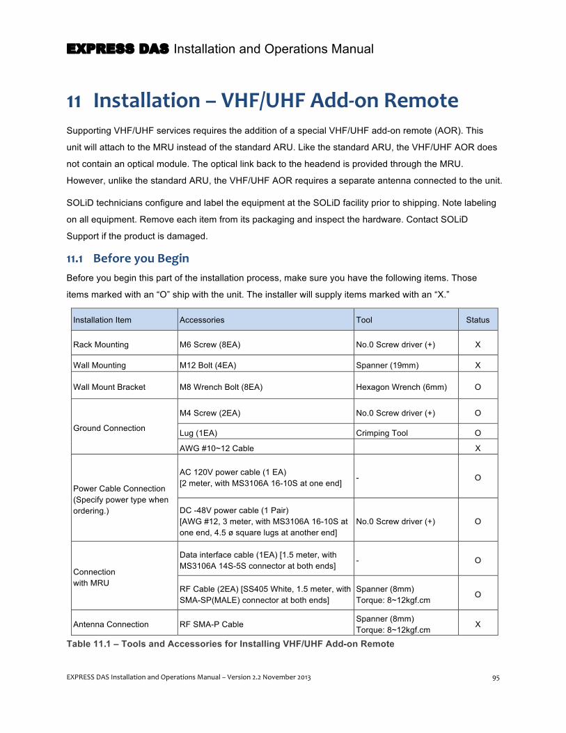
EXPRESS DAS Installation and Operations Manual
EXPRESS DAS Installation and Operations Manual – Version 2.2 November 2013 95
11 Installation – VHF/UHF Add-‐on Remote Supporting VHF/UHF services requires the addition of a special VHF/UHF add-on remote (AOR). This
unit will attach to the MRU instead of the standard ARU. Like the standard ARU, the VHF/UHF AOR does
not contain an optical module. The optical link back to the headend is provided through the MRU.
However, unlike the standard ARU, the VHF/UHF AOR requires a separate antenna connected to the unit.
SOLiD technicians configure and label the equipment at the SOLiD facility prior to shipping. Note labeling
on all equipment. Remove each item from its packaging and inspect the hardware. Contact SOLiD
Support if the product is damaged.
11.1 Before you Begin Before you begin this part of the installation process, make sure you have the following items. Those
items marked with an “O” ship with the unit. The installer will supply items marked with an “X.”
Installation Item Accessories Tool Status
Rack Mounting M6 Screw (8EA) No.0 Screw driver (+) X
Wall Mounting M12 Bolt (4EA) Spanner (19mm) X
Wall Mount Bracket M8 Wrench Bolt (8EA) Hexagon Wrench (6mm) O
Ground Connection
M4 Screw (2EA) No.0 Screw driver (+) O
Lug (1EA) Crimping Tool O
AWG #10~12 Cable X
Power Cable Connection (Specify power type when ordering.)
AC 120V power cable (1 EA) [2 meter, with MS3106A 16-10S at one end]
- O
DC -48V power cable (1 Pair) [AWG #12, 3 meter, with MS3106A 16-10S at one end, 4.5 ø square lugs at another end]
No.0 Screw driver (+) O
Connection with MRU
Data interface cable (1EA) [1.5 meter, with MS3106A 14S-5S connector at both ends]
- O
RF Cable (2EA) [SS405 White, 1.5 meter, with SMA-SP(MALE) connector at both ends]
Spanner (8mm) Torque: 8~12kgf.cm
O
Antenna Connection RF SMA-P Cable Spanner (8mm) Torque: 8~12kgf.cm
X
Table 11.1 – Tools and Accessories for Installing VHF/UHF Add-on Remote

EXPRESS DAS Installation and Operations Manual
96 EXPRESS DAS Installation and Operations Manual – Version 2.2 November 2013
The VHF/UHF AOR can be rack or wall mounted. The cabinet is designed to be water and dirt proof so
can be mounted either indoors or outdoors.
Instructions for both rack and wall mounting are contained in the following sections.
11.2 Installing the VHF/UHF AOR – Wall Mount
The AOR can be mounted above, below or beside the MRU. In all cases, make sure to leave adequate
clearance between the units to increase airflow for effective heat dissipation. At the same time, distance
between the units should not exceed the maximum values shown below. For example, because jumper
cables connect at the bottom of the MRU, when the AOR is connected toward the lower side of the MRU,
the maximum distance will be 700mm. When the AOR is connected at the upper side, the maximum
distance will be 300mm.
Figure 11.1 – Recommended Clearances for VHF/UHF AOR Wall Mounting
NOTE: The following instructions assume the MRU is already installed.

EXPRESS DAS Installation and Operations Manual
EXPRESS DAS Installation and Operations Manual – Version 2.2 November 2013 97
1- Install the M12 fixing screws in the wall according to the dimensions shown in the next figure.
Figure 11.2 – VHF/UHF AOR Wall Mount Dimensions
2- Insert the mounting screws half way into the wall. Mount the bracket and then fully fix the screws.
3- At the top of each side of the enclosure’s heat sink, insert an M5 wrench bolt and turn them in half way.
4- Position the M5 wrench bolts into the mounting groove of the mounting bracket and insert additional
bolts into all the remaining fixing holes. You will need 6 M5 wrench bolts minus the bolts used for the
mounting groove.
5- Tighten down all of the mounting bolts.
Figure 11.3 – Wall Mounting the AOR

EXPRESS DAS Installation and Operations Manual
98 EXPRESS DAS Installation and Operations Manual – Version 2.2 November 2013
11.3 Installing the VHF/UHF AOR – Rack Mounting
The VHF/UHF AOR can be installed in a 19-inch equipment rack, where it requires 4U of rack space. It
can mount either above or below the MRU.
1- Position the unit in the rack.
When positioning the unit in the rack, make sure to leave 2U of space between it and the MRU to allow
for cable installation and air circulation.
2- Insert the M6 screws in the mounting holes and tighten the screws to secure the chassis.
11.4 Installing Power Cabling
The VHF/UHF AOR supports both DC-48V and AC120V for input power. Make sure to order the
appropriate power unit according to your installation requirements. Based on your configuration, SOLiD
will ship the unit with the correct power supply installed and provide the correct power cable with the
connector attached.
All connections are made at the back of the unit. The power connector is slotted and can only be installed
one way. For your information, the following table shows the power connections.
MC Connector Numbering
Lug Naming AOR PSU Terminal naming
AC DC AC DC A AC_H -48V AC-H -48V
B AC_N GND AC-N IN_GND
C GND DC NC FG FG
Table 11.2 – VHF/UHF AOR Power Connections
Figure 11.4 – VHF/UHF AOR Power Port
1- Connect the power cable to the PSU and to the power source.
2- Power on the unit to verify power is connected properly.

EXPRESS DAS Installation and Operations Manual
EXPRESS DAS Installation and Operations Manual – Version 2.2 November 2013 99
11.4.1 VHF/UHF AOR Power Consumption
The following table shows power consumption of the VHF/UHF AOR:
Unit Part No. Power Consumption (W)
VHF/UHF AOR SC_AC_150_450 or SC_DC_150_450 (Includes RDU_150_450)
AOR Chassis 78W + RDU 93W
Table 11.3 – VHF/UHF AOR Power Consumption
11.5 Connecting Ground (GND) Terminal
The unit has one ground terminal port located on the rear side as shown below.
Figure 11.5 – VHF/UHF AOR Ground Port
1- Take off the GND terminal port from the enclosure and connect to the supplied ground cable.
Then reconnect it to the enclosure.
2- Connect the other end of the ground cable to the communication GND of the building.

EXPRESS DAS Installation and Operations Manual
100 EXPRESS DAS Installation and Operations Manual – Version 2.2 November 2013
11.6 Connecting the Add-‐on Unit to the MRU
1- Make all connections between the units according to the following figure and table. Make sure to
observe recommended torque values. Items marked with an “O” ship with the unit. The installer should
provide items marked “X.”
Figure 11.6 – Connecting the MRU to VHF/UHF AOR
No. Item Type Torque Status 1 Tx Cable RF Interface Cable (SMA Male) – Qty 1 8~12kgf.cm O 2 Rx Cable RF Interface Cable (SMA Male) – Qty 1 8~12kgf.cm O 3 Signal Cable Data Interface Cable – Qty 1 - O 4 Ground AWG #10~12 Cable Lug crimper X 5 RX / SISO Antenna Cable RF Interface Cable (SMA Male) – Qty 1 8~12kgf.cm X 6 TX / MIMO Antenna Cable RF Interface Cable (SMA Male) – Qty 1 8~12kgf.cm X 7 Power Cable AC power cable or DC -48V power cable – Qty 1 - O
Table 11.4 – VHF/UHF AOR / MRU Connections
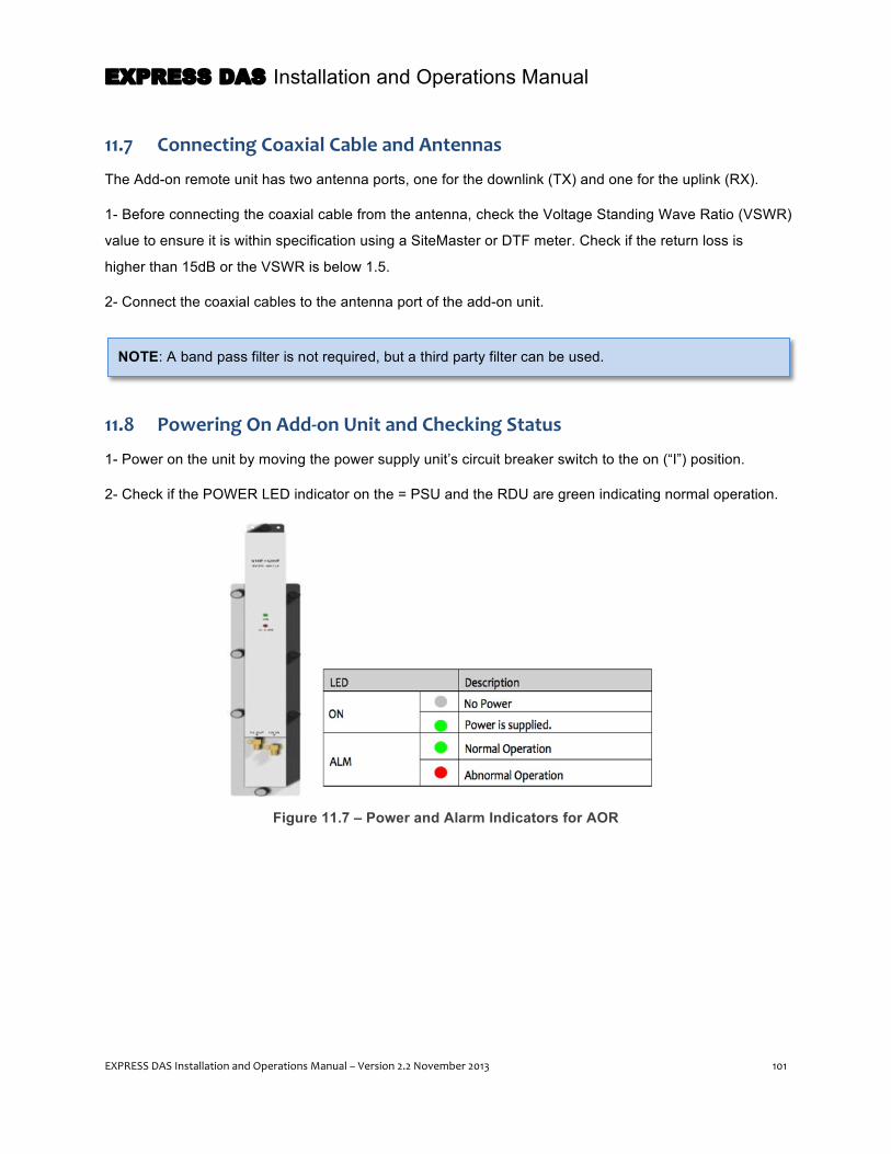
EXPRESS DAS Installation and Operations Manual
EXPRESS DAS Installation and Operations Manual – Version 2.2 November 2013 101
11.7 Connecting Coaxial Cable and Antennas
The Add-on remote unit has two antenna ports, one for the downlink (TX) and one for the uplink (RX).
1- Before connecting the coaxial cable from the antenna, check the Voltage Standing Wave Ratio (VSWR)
value to ensure it is within specification using a SiteMaster or DTF meter. Check if the return loss is
higher than 15dB or the VSWR is below 1.5.
2- Connect the coaxial cables to the antenna port of the add-on unit.
11.8 Powering On Add-‐on Unit and Checking Status
1- Power on the unit by moving the power supply unit’s circuit breaker switch to the on (“I”) position.
2- Check if the POWER LED indicator on the = PSU and the RDU are green indicating normal operation.
Figure 11.7 – Power and Alarm Indicators for AOR
NOTE: A band pass filter is not required, but a third party filter can be used.

EXPRESS DAS Installation and Operations Manual
102 EXPRESS DAS Installation and Operations Manual – Version 2.2 November 2013
12 System Commissioning This section of the manual describes how to commission the DAS once you have completed the
hardware installation. The commissioning process assumes you have a basic understanding of link
budgets and RF technology.
You have two options for the commissioning process: using the EasySETTM auto commissioning feature,
which automatically optimizes the DAS system parameters according to factory defaults, or manually
setting parameters. SOLiD recommends starting the commissioning process with EasySETTM, and if
necessary, adjusting system parameters using the management software.
For either option, you will need a laptop computer or PC connected to the CONSOLE port at the back of
the DMS-600 server. The management software communicates through the DMS-600 with the DAS
components: BIU, OEU and MRU. No special software is required to run the management program; it
operates in a standard Web browser window. SOLiD recommends using Internet Explorer, Google
Chrome or Mozilla Firefox.
12.1 Before you Begin Before you begin this part of the installation process, make sure you have the following items. Those
items marked with an “O” ship with the unit. The installer will supply items marked with an “X.”
Installation Item Accessories Status
PC to DMS-600 Connection Standard CAT5 Ethernet Cable O
Measuring Power Levels from Signal Sources Spectrum analyzer X
Table 12.1 – Tools and Accessories for System Commissioning
NOTE: You can access the management software on the DMS-600 either onsite (with a laptop
connected to the CONSOLE port) or remotely via the Internet (if the DMS unit is connected to a
network with Internet access). SOLiD recommends performing the initial commissioning onsite.
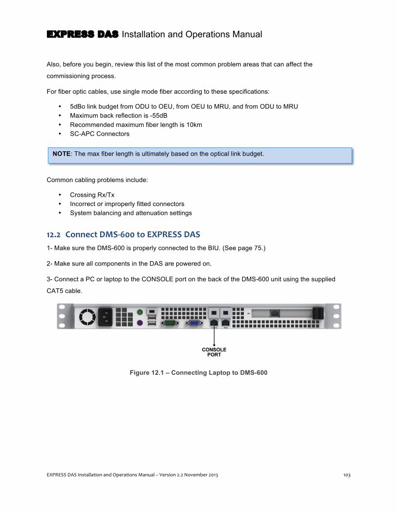
EXPRESS DAS Installation and Operations Manual
EXPRESS DAS Installation and Operations Manual – Version 2.2 November 2013 103
Also, before you begin, review this list of the most common problem areas that can affect the
commissioning process.
For fiber optic cables, use single mode fiber according to these specifications:
• 5dBo link budget from ODU to OEU, from OEU to MRU, and from ODU to MRU • Maximum back reflection is -55dB • Recommended maximum fiber length is 10km • SC-APC Connectors
Common cabling problems include:
• Crossing Rx/Tx • Incorrect or improperly fitted connectors • System balancing and attenuation settings
12.2 Connect DMS-‐600 to EXPRESS DAS 1- Make sure the DMS-600 is properly connected to the BIU. (See page 75.)
2- Make sure all components in the DAS are powered on.
3- Connect a PC or laptop to the CONSOLE port on the back of the DMS-600 unit using the supplied
CAT5 cable.
Figure 12.1 – Connecting Laptop to DMS-600
NOTE: The max fiber length is ultimately based on the optical link budget.
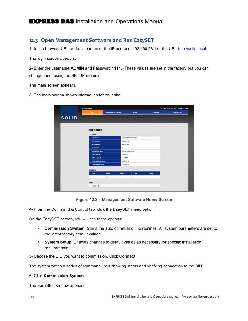
EXPRESS DAS Installation and Operations Manual
104 EXPRESS DAS Installation and Operations Manual – Version 2.2 November 2013
12.3 Open Management Software and Run EasySET 1- In the browser URL address bar, enter the IP address: 192.168.58.1 or the URL http://solid.local
The login screen appears.
2- Enter the username ADMIN and Password 1111. (These values are set in the factory but you can
change them using the SETUP menu.)
The main screen appears.
3- The main screen shows information for your site.
Figure 12.2 – Management Software Home Screen
4- From the Command & Control tab, click the EasySET menu option.
On the EasySET screen, you will see these options:
• Commission System: Starts the auto commissioning routines. All system parameters are set to the latest factory default values.
• System Setup: Enables changes to default values as necessary for specific installation requirements.
5- Choose the BIU you want to commission. Click Connect.
The system writes a series of command lines showing status and verifying connection to the BIU.
6- Click Commission System.
The EasySET window appears.

EXPRESS DAS Installation and Operations Manual
EXPRESS DAS Installation and Operations Manual – Version 2.2 November 2013 105
7- Click Start.
A progress bar indicates the auto-commissioning status. Settings performed by EasySET can be seen in
the command-line window. (Pressing Stop will halt the process.)
Figure 12.3 – EasySET Progress Bar
Once the commissioning procedure is complete (100/100), the final command line will show status:
• Commissioning Successful: No alarms reported.
• Commissioning Failure Alarm Check of System Online: An alarm has been reported.
8- If successful, close the pop-up window to conclude the EasySET process. If the commissioning
process has failed, go to the Command & Control menu to determine the alarm condition.
12.4 Changing Factory Defaults To meet specific performance needs for your DAS site, you can modify factory default values to desired
levels before executing the EasySET function.
1- From the EasySET main screen, click System Setup. The following screen appears with these options:
• Default Load: Displays the stored default values. • Default Save: Default values are applied to parameter values. • GET: Displays the most recently saved parameter values. • SET: Saves the changed parameters values. • Commission System: Executes the EasySET commissioning process • EasySET Main: Back to main Command & Control window.

EXPRESS DAS Installation and Operations Manual
106 EXPRESS DAS Installation and Operations Manual – Version 2.2 November 2013
Figure 12.4 – System Setup Screen
2- Choose the BIU you want to connect to. Click Connect. Press GET to view current parameters.
3- Change values as necessary. When you are done, click SET to save new values. These values will be
applied during the auto commissioning process.

EXPRESS DAS Installation and Operations Manual
EXPRESS DAS Installation and Operations Manual – Version 2.2 November 2013 107
12.5 Manual Setup From the Command & Control menu, you can further customize your DAS settings such as modifying
alarm thresholds and adjusting RF parameters per frequency band.
12.5.1 Load the Command & Control Menu
1- From the main screen, click Command & Control
2- Choose the BIU you want to connect to. Click Connect.
Figure 12.5 – Command & Control Screen
The Auto-ID feature detects the DAS devices currently connected and displays these in the System Tree
along the left side of the display (outlined in red in the above graphic).
3- Select a device from the left menu within the BIU tree.
To read values select the Read button.
To change values select the Set Mode button.
To save values, click Set after changing the parameter value.
4- Click Close when you are done.

EXPRESS DAS Installation and Operations Manual
108 EXPRESS DAS Installation and Operations Manual – Version 2.2 November 2013
12.5.2 Verify all Connections
1- Check the RF input and output cabling and connectors between the BIU and the signal source (BTS or
BDA) to verify all connections are attached properly.
2- Using a spectrum analyzer connected to the Monitor SMA ports at the front of the MDBUs, test the RF
input signal (Tx) for each frequency band and input. Depending on the signal, this value will range
between -20dBm to +10dBm per port.
3- Check the values in the management software in the Tx IN POWER field for each MDBU to verify they
match the results from the spectrum analyzer.
4- In the System Tree, check that all power and optical connections are working properly for both
headend and remote components. A green light indicates the connection is functioning.
5- Check that all headend and remote components are receiving power. 12.5.3 Set MDBU Parameters
1- Activate all input ports being used by selecting ON and then SET.
Turn off all ports not in use. If an unused port remains turned on, output power levels will be
impacted. If there is no input signal, the Tx IN power field will show the value -100dBm.
2- Once turned on, label the input ports by clicking in the label area. Each port name can be up to 12
characters. Press SET when you are done.
3- For each active MDBU, turn on Tx IN AGC by selecting ON and then SET. This will automatically turn
off once complete. This is a one-time setting to adjust the BIU gain against each BIU input level.
Figure 12.6 – Setting MDBU Parameters
5- Turn on Tx IN ALC by selecting ON and pressing SET.
6- Verify Rx OUT ALC is turned OFF.

EXPRESS DAS Installation and Operations Manual
EXPRESS DAS Installation and Operations Manual – Version 2.2 November 2013 109
7- Set the Rx OUT ATT to the value desired for the uplink path.
8- Verify that the value in the Tx IN POWER is within ±3dB of the downlink value measured using the
spectrum analyzer.
12.5.4 Set Optic Compensation
The LD (laser diode) power light is the level of power transmitted by the ODU and received by the MRU.
The PD (photo diode) power light is the level of power received by the MRU and transmitted by the ODU.
The MRU can automatically compensate for optical loss, up to a maximum 5dBo.
1- Select the SISO, ODU, DOU, ROU from the System Tree menu to reach the Optic Information screen.
(In the System Tree, “ROU” refers to the remote optical units such as the MRUs and ARUs.)
Figure 12.7 – Setting Optic Values
2- Check the LD and PD power range and OPTIC ATT to the following values:
• LD Power Range: +7 ± 1.5dBm @1550nm • PD Power Range: +3 to 0dBm @1310nm • Tx Optic ATT: Default 12dB
3- Set Tx OPTIC COMP of MRU to ON.
When you turn on OPTIC COMP, the system automatically calculates the correct compensation by using
the difference between the ODU LD power and MRU PD power results.

EXPRESS DAS Installation and Operations Manual
110 EXPRESS DAS Installation and Operations Manual – Version 2.2 November 2013
During optical compensation, the RESULT field will display PROCESSING and then show the result:
• Success: Optic compensation is successfully performed. • Over Optic Loss: Optic loss exceeds 5dBo. • Communication Fail: Communication between ODU and MRU failed.
When activating OPTIC COMP (by setting it to ON), the system performs optic compensation at the MRU
side and the result is applied to the ODU.
The system automatically calculates optic compensation according to the following values.
Recommended values should fall between 1dBo~5dBo:
1dBo~5dBo
LD Power [dBm] PD Power [dBm] LD-PD OPT ATT[dB] 12-2* (LD-PD-1)
Optic Loss
1.5 ± 1
0.5 1 12 1dBo 0 1.5 11
-0.5 2 10 2dBo -1 2.5 9
-1.5 3 8 3dBo -2 3.5 7
-2.5 4 6 4dBo -3 4.5 5
-3.5 5 4 5dBo -4 5.5 3
-4.5 6 2 6dBo
Table 12.2 – Optic Compensation
If the MRU does not perform optical compensation, there will be errors in the link budget of the system. This can cause reduced output levels and/or generate harmful spurious emissions.
NOTE: Optic compensation depends on a working communication between the ODU and MRU. A
faulty connection or a malfunctioning R_Optic or DOU module could cause a failure in this
communication.

EXPRESS DAS Installation and Operations Manual
EXPRESS DAS Installation and Operations Manual – Version 2.2 November 2013 111
12.5.5 Set MRU/ARU Parameters
1- Using the System Tree menu, select the MRU to configure.
2- Turn the relevant band on by selecting ON and pressing SET.
Figure 12.8 – Configuration Screen
3- Before turning on HPA, confirm that optic compensation has been performed. Click On TX HPA then
click Set.
4- Click On Tx OUTPUT AGS then click Set.
When this function is turned on, the system will set the MRU gain to the target level. While the AGS
function is being executed, the RESULT field will display PROCESSING and then shows the result:
• Success: The AGS function is accomplished. • Not Operate OPTIC Comp: Optic compensation is not accomplished. • Lack of ATT: There is no attenuation available.
If optic compensation fails, return to previous section. Otherwise, move to next step.
EXPRESS DAS Installation and Operations Manual
112 EXPRESS DAS Installation and Operations Manual – Version 2.2 November 2013
5- Click On Tx OUTPUT ALC then click Set.
Once AGS is performed, the ALC (Auto Level Control) function will maintain the set target level.
6- Click On Tx OUTPUT SD then click Set to turn on the auto shutdown feature.
(See page 119 to learn more about this feature.)
7- Set the Tx ROU parameters for AGS, ALC, SD and TX OUT HIGH/LOW levels according to the
requirements of your site.
8- Set the Rx ROU parameter for ATT levels depending on your requirements.
9- Set Rx IN ALC level to -50dBm.
12.6 System Acceptance Before the DAS goes live, you can validate that you have successfully completed the commissioning
process and all components are functioning properly by checking signal levels for both the uplink and
downlink paths as shown in the following figures. The table shows suggested link budget values, which
will vary according to the configuration and frequencies of your system.
The validation process requires a signal generator and a spectrum analyzer. Set the spectrum analyzer
to: 10 kHz resolution bandwidth, 3 kHz video bandwidth, 1 MHz frequency span.
NOTE: During system acceptance, make sure the system is operating within the recommended
frequencies according to each band. See the table on page 11.
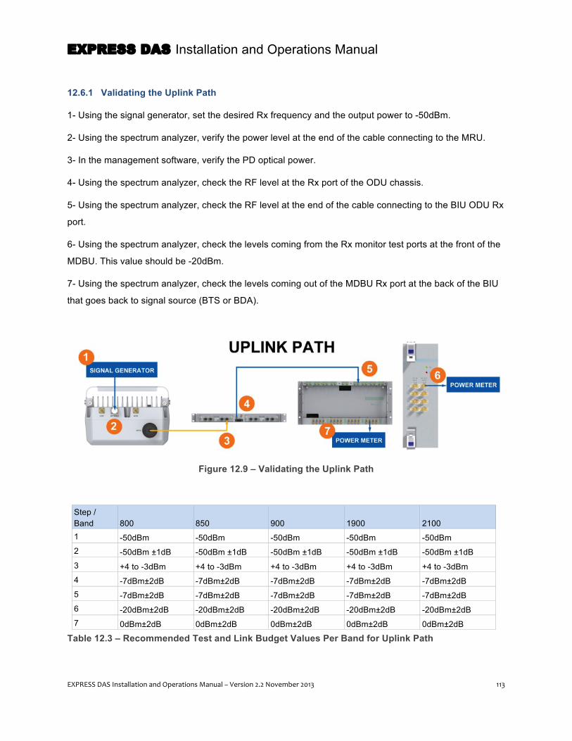
EXPRESS DAS Installation and Operations Manual
EXPRESS DAS Installation and Operations Manual – Version 2.2 November 2013 113
12.6.1 Validating the Uplink Path
1- Using the signal generator, set the desired Rx frequency and the output power to -50dBm.
2- Using the spectrum analyzer, verify the power level at the end of the cable connecting to the MRU.
3- In the management software, verify the PD optical power.
4- Using the spectrum analyzer, check the RF level at the Rx port of the ODU chassis.
5- Using the spectrum analyzer, check the RF level at the end of the cable connecting to the BIU ODU Rx
port.
6- Using the spectrum analyzer, check the levels coming from the Rx monitor test ports at the front of the
MDBU. This value should be -20dBm.
7- Using the spectrum analyzer, check the levels coming out of the MDBU Rx port at the back of the BIU
that goes back to signal source (BTS or BDA).
Figure 12.9 – Validating the Uplink Path
Step / Band 800 850 900 1900 2100 1 -50dBm -50dBm -50dBm -50dBm -50dBm 2 -50dBm ±1dB -50dBm ±1dB -50dBm ±1dB -50dBm ±1dB -50dBm ±1dB 3 +4 to -3dBm +4 to -3dBm +4 to -3dBm +4 to -3dBm +4 to -3dBm 4 -7dBm±2dB -7dBm±2dB -7dBm±2dB -7dBm±2dB -7dBm±2dB 5 -7dBm±2dB -7dBm±2dB -7dBm±2dB -7dBm±2dB -7dBm±2dB 6 -20dBm±2dB -20dBm±2dB -20dBm±2dB -20dBm±2dB -20dBm±2dB 7 0dBm±2dB 0dBm±2dB 0dBm±2dB 0dBm±2dB 0dBm±2dB
Table 12.3 – Recommended Test and Link Budget Values Per Band for Uplink Path

EXPRESS DAS Installation and Operations Manual
114 EXPRESS DAS Installation and Operations Manual – Version 2.2 November 2013
12.6.2 Validating the Downlink Path
1. Using the signal generator, set the desired Tx frequency and the output power to 0dBm.
2. Using the spectrum analyzer, verify the power level at the end of the cable connecting to the MDBU Tx
port at the BIU.
3. Using the spectrum analyzer, check the levels coming from the Tx monitor test ports at the front of the
MDBU. When the signal source is 0dBm, this value should be -20dBm.
4. Using the spectrum analyzer, check the levels coming from the BIU ODU Tx port.
5. Using the spectrum analyzer, check the levels at the end of the cable connection to the Tx port on the
ODU.
6. In the management software, verify the LD optical power.
7. Using the spectrum analyzer, check the levels coming out of the antenna port at the bottom of the
MRU.
Figure 12.10 – Validating the Downlink Path
Step / Band 800 850 900 1900 2100 1 0dBm 0dBm 0dBm 0dBm 0dBm 2 0dBm±1dB 0dBm±1dB 0dBm±1dB 0dBm±1dB 0dBm±1dB 3 -20dBm±2dB -20dBm±2dB -20dBm±2dB -20dBm±2dB -20dBm±2dB 4 -8dBm±2dB -8dBm±2dB -8dBm±2dB -8dBm±2dB -8dBm±2dB 5 -8dBm±2dB -8dBm±2dB -8dBm±2dB -8dBm±2dB -8dBm±2dB 6 +7dBm±1.5dB +7dBm±1.5dB +7dBm±1.5dB +7dBm±1.5dB +7dBm±1.5dB 7 +25dBm±2dB +26dBm±2dB +25dBm±2dB +30dBm±2dB +30dBm±2dB
Table 12.4 – Recommended Test and Link Budget Values Per Band for Downlink Path
If the measured values for your system match the table above, congratulations! You have successfully
completed the installation and commissioning process. If not, consult the tables below, which explain fault
indicators and suggested remedies.

EXPRESS DAS Installation and Operations Manual
EXPRESS DAS Installation and Operations Manual – Version 2.2 November 2013 115
12.7 Alarm Troubleshooting This section of the manual explains alarm indicators in the management software and provides tips on
resolving alarms.
No LED Status Description
1 Normal Status
2 Abnormal or Warning Status
Table 12.5 – Alarm Indicators in Management Software
12.7.1 ODU Alarm Troubleshooting
Unit ALARM Cause Management
DOU
Overload Alarm Tx input level to DOU is too high Check output power of MDBU Check input power of MDBU
LD POWER Failure of DOU PSU not at +9V
Replace DOU Using DVM, check voltage of +9V
PD POWER
Optical loss is too high Loose optical port Over-curvature or cut optical cable MRU power supply turned off
Using optical power meter, check received optical power level Check MRU power
Table 12.6 – ODU Alarm Indicators in Management Software

EXPRESS DAS Installation and Operations Manual
116 EXPRESS DAS Installation and Operations Manual – Version 2.2 November 2013
12.7.2 BIU Alarm Troubleshooting
Unit ALARM Cause Management
MPSU DC ALM Output over current Output low voltage
Using DVM, check -48/ +9/+6V voltage levels Pull out each module (MDBU, MCPU) and find failed module Replace MPSU
MCPU
High Temp Limit
Incorrect setting of upper temp limit level Exceeding operating temp range Failure of temp sensor
Adjust upper temp limit level Check operating temp range Replace MCPU
Low Temp Limit
Incorrect setting of lower temp limit level Exceeding operating temp range Failure of temp sensor
Adjust lower temp limit level Check operating temp range Replace MCPU
Ext.ALM#1~4
External device alarm Cross-connect of N.O and N.C Failure of relay component in the MCPU
Reconnect N.O and N.C Replace MCPU
ALM In #1~3 External device alarm Cross-connect GND and ALM In Wrong setting of active high/low
Reconnect GND and ALM In Set again for active high/low Replace MCPU
MDBU
Tx IN HIGH Input power exceeds high limit level
Reset high limit level Check input power of MDBU using spectrum analyzer Replace MDBU
Tx IN LOW Input power falls below low limit level
Reset low limit level Check input power of MDBU using spectrum analyzer Replace MDBU
Rx OUT HIGH Output power exceeds high limit level
Reset high limit level Check output power of MDBU using spectrum analyzer Replace MDBU
Table 12.7 – BIU Alarm Indicators in Management Software
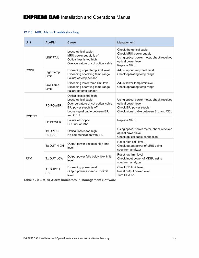
EXPRESS DAS Installation and Operations Manual
EXPRESS DAS Installation and Operations Manual – Version 2.2 November 2013 117
12.7.3 MRU Alarm Troubleshooting
Unit ALARM Cause Management
RCPU
LINK FAIL
Loose optical cable MRU power supply is off Optical loss is too high Over-curvature or cut optical cable
Check the optical cable Check MRU power supply Using optical power meter, check received optical power level Replace MRU
High Temp Limit
Exceeding upper temp limit level Exceeding operating temp range Failure of temp sensor
Adjust upper temp limit level Check operating temp range
Low Temp Limit
Exceeding lower temp limit level Exceeding operating temp range Failure of temp sensor
Adjust lower temp limit level Check operating temp range
ROPTIC
PD POWER
Optical loss is too high Loose optical cable Over-curvature or cut optical cable BIU power supply is off Loose signal cable between BIU and ODU
Using optical power meter, check received optical power level Check BIU power supply Check signal cable between BIU and ODU
LD POWER Failure of R-optic PSU not at +9V
Replace MRU
Tx OPTIC RESULT
Optical loss is too high No communication with BIU
Using optical power meter, check received optical power level Check optical cable connection
RFM
Tx OUT HIGH Output power exceeds high limit level
Reset high limit level Check output power of MRU using spectrum analyzer
Tx OUT LOW Output power falls below low limit level
Reset low limit level Check input power of MDBU using spectrum analyzer
Tx OUPTU SD
Exceeding power level Output power exceeds SD limit level
Check SD limit level Reset output power level Turn HPA on
Table 12.8 – MRU Alarm Indicators in Management Software

EXPRESS DAS Installation and Operations Manual
118 EXPRESS DAS Installation and Operations Manual – Version 2.2 November 2013
12.7.4 OEU Alarm Troubleshooting
Unit ALARM Cause Management
EPSU DC Alarm Output over current Output low voltage
Using DVM, check -48V/+9V/+6V voltage levels Check each module (DOU, EWDM, ERFU) and find failed module Replace EPSU
ECPU
High Temp Limit
Incorrect setting of upper temp limit level Exceeding operating temp range Failure of temp sensor
Adjust upper temp limit level Check operating temp range
Low Temp Limit
Incorrect setting of low temp limit level Exceeding operating temp range Failure of temp sensor
Adjust lower temp limit level Check operating temp range
LINK FAIL
Loose optical cable BIU power supply is off Optical loss is too high Over-curvature or cut cable
Check the optical cable Check BIU power supply Using optical power meter, check received optical power level
EOPTIC
PD POWER
Loose optical cable BIU power supply is off Optical loss is too high Over-curvature or cut cable
Check the optical cable Check BIU power supply Using optical power meter, check received optical power level
LD POWER Failure of R-optic PSU not at +9V
Replace MRU
RESULT Optical loss is too high No communication with BIU
Using optical power meter, check received optical power level Check optical cable connection
DOU
Overload Alarm Tx input level to DOU is too high Check output power of MDBU Check input power of MDBU
LD POWER Failure of DOU PSU not at +9V
Replace DOU Using DVM, check voltage of +9V
PD POWER
Loose optical cable MRU power supply is off Optical loss is too high Over-curvature or cut cable
Check the optical cable Check MRU power supply Using optical power meter, check received optical power level
Table 12.9 – OEU Alarm Indicators in Management Software

EXPRESS DAS Installation and Operations Manual
EXPRESS DAS Installation and Operations Manual – Version 2.2 November 2013 119
13 Appendix – Additional Functions This chapter describes additional functions of the EXPRESS DAS.
13.1 Shutdown Function (Tx Output Shutdown) The DAS has an automatic shutdown function to protect the headend and remote units when normal
operating conditions cannot be maintained. For example, the DAS shuts down automatically when the
composite downlink output power exceeds the values defined as average for the device for more than five
seconds. This time period can be adjusted in the management software.
After automatic shutdown, the DAS may automatically restart in order to assess whether the temporary
condition has changed. If the condition is still detected, the DAS will shutdown again. This cycle will be
repeated five times. After the fifth time, if the condition is still detected, the DAS will shutdown
permanently.
13.2 Total Power Limit Function (Tx Output ALC) In order to protect the HPA and prevent spurious emissions, you can set maximum output power limits.
To do this, in the management software, turn on the ALC function and set the limit level. If the output
power exceeds the defined value, the output attenuator is adjusted to bring the output power back to
within the set limits. The output attenuator’s adjustment range is 25dB max. If output power decreases,
attenuation is decreased using the AGC function to return to the initial attenuation level.
NOTE: This material is offered “for your information.” The system software automatically performs
many of the functions described here. Others are user-defined functions already covered in the
commissioning section.
NOTE: A permanent shutdown will produce a fault alarm and will be reported to the Network
Operating Center (NOC) through the DMS-600.

EXPRESS DAS Installation and Operations Manual
120 EXPRESS DAS Installation and Operations Manual – Version 2.2 November 2013
13.3 Automatic Output Power Setting Function (Tx Output AGC) To make it easier to set initial output power, you can set the output power to the desired level and turn on
the AGC function. The system will automatically set output power to this level.
After you set the AGC level, the RESULT window will indicate the outcome:
• Success: The AGC function is properly completed. • Not Operate OPTIC Comp: Optic Comp is not executed. • Lack of ATT: There is no attenuation available.
If the result is not successful, the system will return the changed ATT to the initial ATT level.
13.4 Input Power AGC Function (Tx Input AGC) Besides using a spectrum analyzer, you can also determine the input power value through the
management software’s power display window. You can use the Tx IN AGC function to automatically set
internal attenuation depending on the input level. The attenuation is automatically set based on -20dBm
of input. The table below shows Tx IN ATT as a function of the Tx IN POWER. For making these settings
manually, you can use the table to set the attenuation depending on the input level.
Tx IN POWER Tx IN ATT Tx IN POWER Tx IN ATT Tx IN POWER Tx IN ATT
-20dBm 0dB -9dBm 11dB +1dBm 21dB
-19dBm 1dB -8dBm 12dB +2dBm 22dB
-18dBm 2dB -7dBm 13dB +3dBm 23dB
-17dBm 3dB -6dBm 14dB +4dBm 24dB
-16dBm 4dB -5dBm 15dB +5dBm 25dB
-15dBm 5dB -4dBm 16dB +6dBm 26dB
-14dBm 6dB -3dBm 17dB +7dBm 27dB
-13dBm 7dB -2dBm 18dB +8dBm 28dB
-12dBm 8dB -1dBm 19dB +9dBm 29dB -11dBm 9dB 0dBm 20dB +10dBm 30dB -10dBm 10dB
Table 13.1 – Attenuation (ATT) Level Values

EXPRESS DAS Installation and Operations Manual
EXPRESS DAS Installation and Operations Manual – Version 2.2 November 2013 121
13.5 Input Power Limit Function (Tx Input ALC) A Tx input Auto Level Control function built into the BIU can limit input power levels if the increase past
the limit set by the input AGC function. For example, in the case where the 850 cellular band has two
input ports to support both two different carriers, these input powers may be different from each other.
There is an input attenuator in the first stage of the MDBU. Through the input AGC function, the input ATT
is adjusted according to input power. If input power increases, the input ATT is adjusted to limit the this
increase. If the input power decreases, the input ATT will return to the initial ATT setting.
13.6 Optic Loss Compensation The DAS can automatically compensate for optical loss up to a maximum 5dBo. To turn on this feature,
set Tx OPTIC COMP of the MRU to ON and ensure the MRU/ARU is properly communicating with the
ODU or OEU. For 1dBo of optical loss, set the Tx OPTIC ATT at 1dB; for 5dBo of optical loss, set Tx
OPTIC ATT at 4dB. OPTIC COMP works only one time before it stays dormant.
LD POWER is the output level of the MRU Laser Diode, which is sent back to the headend by the MRU.
PD POWER is the input level of the Photo Diode signal from the headend. The figure below shows a
screenshot for Optical Information in the MRU setup screen.
Figure 13.1 – Optical Loss Information
During optical compensation, the RESULT field will display PROCESSING and then show the result:
• Success: Optic compensation is successfully performed • Over Optic Loss: Optic loss exceeds 5dBo • Communication Fail: Communication between the ODU and MRU failed.

EXPRESS DAS Installation and Operations Manual
122 EXPRESS DAS Installation and Operations Manual – Version 2.2 November 2013
14 Appendix – EXPRESS Part Numbers Description Part Number
BIU (Base Station Interface Unit) Signal Source Inputs BIU - MIMO (Includes DC/DC PS, MCPU Card, 2 MCDU Cards) NOTE: Input Power -48VDC. Power supply not included. SC_BIU_MIMO BIU - SISO (Includes DC/DC PS, MCPU Card, MCDU Card, 3 Blanks) NOTE: Input Power -48VDC. Power supply not included. SC_BIU_SISO
DMS Supporting Bracket SC_DMS_BRK
MCDU Combiner Module for the SC_BIU SC_MCDU
Blank Input Module for the SC_BIU SC_MCDU_B
EXPRESS BIU CPU SC_MCPU
1900MHz Input Module for the SC_BIU SC_MDBU_1900
700MHz LTE & 2100MHz Input Module for the SC_BIU SC_MDBU_700LTE_2100
700MHz PS & 800MHz PS Input Module for the SC_BIU SC_MDBU_700_800
800MHz & 900MHz Input Module for the SC_BIU SC_MDBU_800_900
850MHz & 1900MHz Input Module for the SC_BIU SC_MDBU_850_1900
Blank Input Module for the SC_BIU SC_MDBU_B
Power Supply for the SC_BIU SC_MPSU
Table 14.1 – BIU Part Numbers
Description Part Number ODU/OEU Optical Distribution and Expansion Units
Blank Optical Module for the ODU SC_ODU_B / SC_OEU_B
Optical Distribution Unit Chassis SC_ODU_C
4 Port Optical Module SC_ODU_OM_4 / SC_OEU_OM_4
OEU Chassis. NOTE: Input Power -48VDC. Power supply not included. SC_OEU_C
Table 14.2 – ODU/OEU Part Numbers

EXPRESS DAS Installation and Operations Manual
EXPRESS DAS Installation and Operations Manual – Version 2.2 November 2013 123
Description Part Number
MRU and ARU (Main and Add-on Remote Units)
1900 MHz Main Remote Unit - AC Power MRU_AC_1900
1900 MHz Main Remote Unit - AC Power - NEMA MRU_AC_1900_N
1900 MHz Main Remote Unit - DC Power MRU_DC_1900
1900 MHz Main Remote Unit - DC Power - NEMA MRU_DC_1900_N
700 MHz & 2100 MHz Main Remote Unit - AC Power MRU_AC_700_2100
700 MHz PS & 800 MHz PS Main Remote Unit - AC Power - NEMA Enclosure MRU_AC_700_800_N
700 MHz PS & 800 MHz PS Main Remote Unit - DC Power - NEMA Enclosure MRU_DC_700_800_N
850 MHz & 1900 MHz Main Remote Unit - AC Power MRU_AC_850_1900
850 MHz & 1900 MHz Main Remote Unit - AC Power - NEMA Enclosure MRU_AC_850_1900_N
850 MHz & 1900 MHz Main Remote Unit - DC Power MRU_DC_850_1900
700MHz LTE & 2100 MHz Add-on Remote Unit - AC Power ARU_AC_700LTE_2100
700MHz LTE & 2100 MHz Add-on Remote Unit - AC Power - NEMA Enclosure ARU_AC_700LTE_2100_N
700MHz LTE & 2100 MHz Add-on Remote Unit - DC Power ARU_DC_700LTE_2100
800 MHz & 900 MHz Add-on Remote Unit - AC Power ARU_AC_800_900
800 MHz & 900 MHz Add-on Remote Unit - AC Power - NEMA ARU_AC_800_900_N
800 MHz & 900 MHz Add-on Remote Unit - DC Power ARU_DC_800_900
800 MHz & 900 MHz Add-on Remote Unit - DC Power - NEMA ARU_DC_800_900_N
150MHz VHF & 450MHz UHF Amplifier Module with AC Add-on Cabinet - NEMA SC_AC_150_450
150MHz VHF & 450MHz UHF Amplifier Module with DC Add-on Cabinet - NEMA SC_DC_150_450
Stacking MRU Wall Mounting Kit (Stacks ARU on top of MRU) SC_ARU_STK
AC Power Supply Unit for MRU/ARU SC_PUS_AC
19" Rack MRU/ARU Chassis (4U Rack Space Requirement) SC_RM19
Vertical Rack Mount MRU/ARU (9U Rack Space Requirement) SC_RU_BRK
Table 14.3 – MRU and ARU Part Numbers
Description Part Number
DMS-600 (DAS Management System)
DAS Management System (DMS) for EXPRESS DMS_600
DAS Management System (DMS) for EXPRESS. NOTE: Sprint use only DMS_700
Table 14.4 – DMS-600 Part Numbers

EXPRESS DAS Installation and Operations Manual
124 EXPRESS DAS Installation and Operations Manual – Version 2.2 November 2013
Description Part Number
LBU (LINK BALANCER UNIT)
LINK BALANCER UNIT - 2100MHz / 2100MHz, 50dB UL/DL Variable Attenuation LBU_2121F0V4
LINK BALANCER UNIT - 700MHz / 700MHz, 50dB UL/DL Variable Attenuation LBU_7070FOV4
LINK BALANCER UNIT - 800MHz / 800MHz, 50dB UL/DL Variable Attenuation LBU_8080F0V4
LINK BALANCER UNIT - 850MHz / 1900MHz, 50dB UL/DL Variable Attenuation LBU_8519F0V4
LINK BALANCER UNIT - 850MHz / 850MHz, 50dB UL/DL Variable Attenuation LBU_8585F0V4
LINK BALANCER UNIT - 1900MHz / 1900MHz, 50dB UL/DL Variable Attenuation LBU_1919F0V4
Table 14.5 – Link Balancer Unit Part Numbers
EXPRESS DAS Installation and Operations Manual
EXPRESS DAS Installation and Operations Manual – Version 2.2 November 2013 125
15 Appendix – Glossary of Terms The following terms, acronyms and abbreviations appear in this manual :
Attenuation (ATT) – Reducing signal strength during transmission. Attenuation is the opposite of
amplification.
Automatic Gain Control (AGC) – AGC is widely used in communication systems to maintain constant
signal strength by varying the amplifier gain.
Band Pass Filter (BPF) – A device that passes frequencies within a certain range and rejects (attenuates)
frequencies outside that range.
Base Station Interface Unit (BIU) – The unit in the SOLiD DAS topology that receives, combines, and
filters all the signal sources, and then sends them to the ODU.
Coaxial Cable – Cable used for transmitting high-frequency signals. The coaxial cables handle all
frequencies at one time from below 150MHz to over 3GHz. Also called: coax cable.
Distributed Antenna System (DAS) – A network made up of several components that work together to
provide wireless service within a building or campus environment.
Donor Antenna – An antenna mounted outside, usually on top of a building, designed to obtain the
maximum signal and coverage for a specific repeater system. Donor antennas can be a Yagi, Grid, or
Omni-Directional.
Frequency Shift Keying (FSK) – A frequency modulation scheme in which digital information is
transmitted through discrete frequency changes of a carrier wave.
Hot Swappable – A feature that allows one module to be removed while another module maintains all
other services.
MIMO – Abbreviation for Multiple-Input and Multiple-Output. The use of multiple antennas to improve
communication performance.
Multi-Mode fiber – A type of optical fiber commonly used for communication over short distances, such
as within a building or on a campus.
NFPA 72 Code – A standard in the enforcement of fire code regulation published by the National Fire
Protection Association.
Optical Distribution Unit (ODU) – The ODU converts the RF signal to an optical signal and transmits it
via fiber to the MRU.

EXPRESS DAS Installation and Operations Manual
126 EXPRESS DAS Installation and Operations Manual – Version 2.2 November 2013
Optical Expansion Unit (OEU) – The unit in the SOLiD DAS topology that expands a DAS to include
multiple buildings and structures using only one strand of fiber.
Optical Fiber – A thin, glass or plastic thread that carries information in the form of light: a fiber- optic
thread.
Radio Frequency (RF) – Electromagnetic wave frequencies used for communications signals, including
radio, television broadcasting, cell phone, and satellite transmissions.
Received Signal Strength Indication– the ratio of pilot power to total power for each sector.
EC/Io – The Ec/I0 is the energy per chip per interference density measured on the pilot channel; it is
effectively the signal strength of the pilot channel.
Main Remote Unit (MRU) – The unit in the SOLiD DAS topology that amplifies each of the signals
individually, and then sends the signals to the antennas via coax.
SAW filtering – Surface Acoustic Wave filtering cleans up the RF signal, overcomes the thermal noise,
and allows for properly filtered signals to be transported over the optical medium.
SNMP – (Simple Network Management Protocol) is an Internet-standard protocol for managing devices
on IP networks.
Remote Drive Unit (RDU) – Filters and high amplifies DOWNLINK (Tx) signals; Filters and amplifies
UPLINK( Rx) signals.
Voltage Standing Wave Ratio – The ratio between the maximum standing wave amplitude and the
minimum standing wave value.
Wavelength Division Multiplexing (WDM) – In fiber optic communications, wavelength-division
multiplexing is a technology that multiplexes a number of optical carrier signals onto a single optical fiber
by using different wavelengths of laser light.