extend your reach - atecorp.com your reach farran technology ... radio communications and radar...
TRANSCRIPT

EXTEND YOUR REACH
50 - 75 GHz | 60 - 90 GHz | 75 - 110 GHz

CobaltFx
50 - 75 GHz
75 - 110 GHz60 - 90 GHz

Extend Your ReachFarran Technology and Copper Mountain Technologies, globally recognized innovators, with a combined 50 years’ experience in RF test and measurement systems have partnered to create CobaltFx; your new millimeter-wave frequency extension solution.
CobaltFX is the first mmWave frequency extension solution that utilizes a 9 GHz VNA. CobaltFx’s high dynamic range and directivity allow for highly accurate and stable millimeter-wave S-parameter measurements in three dedicated waveguide bands 50-75 GHz, 60-90 GHz and 75-110 GHz. CobaltFx offers an unparalleled combination of price, performance, flexibility and size.
C4209, the VNA used in this system, is from Copper Mountain Technologies’ industry leading Cobalt Series. It features fast sweep speeds down to 10 microseconds per point and a dynamic range of up to 162 dB, all comprised in a compact, USB form factor. C4209 works seamlessly with Farran Technology’s millimeter-wave FEV frequency extenders.
The extenders are packaged in small and versatile enclosures, that allow for flexible port arrangements with respect to the waveguide. Waveguide ports are manufactured in accordance to the new IEEE 1785-2a standard and ensure industry best alignment and repeatability of connection, allowing for long interval times between calibration. The system comes with a precision calibration kit containing flush short, offset piece and broadband load and allows for full 12-term port calibration.
visit www.coppermountaintech.com or www.farran.com for more information.

Antenna Range MeasurementsDue to high free space loss between the transmitting and receiving antennas near and far field antenna as well as radar cross section measurements require high dynamic range and fast sweeping test system. During the measurement antenna gain, pattern, efficiency and directivity can be verified as well as parameters of the radome. While directivity and reflectivity measurements are fundamental for evaluating the backscatter parameters of the target. All these measurements can be performed by a millimetre wave S-parameter measurement system and CobaltFx is a perfect solution for it. CobaltFx offers industry leading dynamic range and sweep time as well as stability and ease of use.
5G Applications5G technology is considered to be fundamental medium for Internet of Things (IoT). It is believed that it will enable very diverse bandwidth usage with extreme range of requirements (up to 1Tb/s/km2 by 2030). With 3D/4K video streaming, vast millimetre wave and smart camera sensor networks, working in the cloud, autonomous driving and mission critical broadcasting all planned to be part of IoT the need for bandwidth and data transmission speed has never been greater. Unlocking the high frequency part of the frequency spectrum (>50 GHz) is fundamental to this concept. Such system will be based on small antennas operating in single as well as multiple user arrangement with beamforming capabilities where amplitude and phase shift need to be very well characterised. Base stations as
well as handset devices will require comprehensive discrete component as well as system level characterisation. The system to be deployed and consumer devices need to comply with very strict specifications and emission requirements but also meet low cost requirements. CobaltFx is the most cost effective solution to enable the integration of various devices, materials, antenna beamforming and channel propagation concepts for indoor and outdoor 5G communication.
Bench-top DUT CharacterizationBench top S-parameters measurements are allow for accurate and time effective verification of packaged products. Every test laboratory in a commercial or industry orientated organisation involved in production and testing of various components must have means of evaluating their products. These normally involve a DUT type unilateral or bilateral S-parameters measurement of passive and active components, compression point measurements for amplifiers and mixers and intermodulation distortion. The measurement domain is either frequency or time. CobaltFx again is a system that allows for all these measurements and with its flexibility and compactness it easily fits on the bench. It also fits the financial constraints that every commercial driven organisation must take into account.What all these application have in common is that they require accurate, compact and affordable millimetre waver test and measurement solution and CobaltFx is meets all these criteria.
Applications & Examples

Material CharacterizationIncrease in usage of millimetre waves for high speed digital radio communications and radar sensors is driving the need for high frequency characterisation of various materials: PCB laminates, antenna radomes and lenses, vehicle windscreens and various other dielectric composites. Accurate characterisation is fundamental to understanding frequency dependent dielectric constant and loss tangents that allow for better modelling of structures, shorter development time and ultimately lower cost of the product. CobaltFx system is designed to be used for various methods of material characterisation – free space, transmission line and resonance type. It offers accurate, compact and cost effective way of understanding what impact on high frequency performance in todays and future mm-wave components and systems various materials would have.
WiGig at 60 GHzMulti Gigabit WiFi technology operating at 60 GHz will expand the capacity for indoor WiFi data transmission. With 3D and 4K video streaming within the wireless network and devices there is a need for chipset and antenna technology to offer bandwidth and range that will reliably replace cable connectivity. Such application puts big constraints on the cost of router as well as wireless devices. High level of integration of various technologies operating from single MHz to 60 GHz range requires very accurate and thorough characterisation of consumer electronics equipment. CobaltFx is a system that allows for very cost effective, accurate and flexible verification of the product at the device level or a system allowing for low cost production.
Automotive Radar & Sensor TestingWith various automotive and non-automotive radar sensors the need for thorough characterisations of devices and materials at 77 and 79 GHz has never been greater. With adaptive cruise control (ACC), collision mitigation (CM) and pedestrian detection (PD) systems already available and
autonomous driving under development the automotive industry is in need for cost and time effective test solution for radar sensors.
Also non-automotive 77 GHz FMCW radar applications that cover foreign object detection, perimeter and security detection, collision avoidance and moving object detection also require test and measurement systems during their development and production. CobaltFx offers the most cost effective and flexible T&M solution for radar applications on the market.
On Wafer S-parameters MeasurementsOn wafer S-parameters measurements provide for model generation of discrete semiconductor devices (diodes, transistors, mmics etc). For accurate models the data obtained during measurements must be accurate and the system must allow for long time intervals between calibrations for the development cost reduction. Such tasks require that millimetre-wave test equipment is stable and accurate at the same time being compact and flexible. CobaltFx fits in those two criteria perfectly.
Backhaul at 70 & 80 GHz
Backhaul radio communication is another technology that supports mobile data networks and IoT in the future. The technology provides short range 1-3 km, high speed 1-2 Gb/s radio transmission for existing mobile networks. Due to its flexibility, ease of deployment and capacity it is frequently used for point-to-point links where fibre networks are not feasible from an environment point of view (water crossing etc.) or cost. Thorough characterisation of passive and active devices (amplifiers, filters, up and down-converters, antennas) is always required as these systems must meet stringent spectrum mask requirements for licensed frequency range. CobaltFx is a system that allows for cost and time effective measurement Backhaul components and subsystems.

C4209 Front
C4209 Back

Extender Top
Extender Side
Extender Back
Extender Bottom
Extender Front

Measured parametersS11, S21, S12, S22 and absolute power of the reference and received signals at the port.
Number of measurement channelsUp to 16 independent logical channels: each logical channel is represented on the screen as an individual channel window. A logical channel is defined by such stimulus signal settings as frequency range, number of test points, or power level.
Data tracesUp to 16 data traces can be displayed in each channel window. A data trace represents one of such parameters of the DUT as S-parameters, response in time domain, input power response.
Memory tracesEach of the 16 data traces can be saved into memory for further comparison with the current values.
Data display formatsLogarithmic magnitude, linear magnitude, phase, expanded phase, group delay, SWR, real part, imaginary part, Smith chart diagram and polar diagram display formats are available.
Dynamic Range vs IF BandwidthDynamic range is defined as the difference between the data trace of the transmission magnitudefor both test ports through connected at maximum output power and the mean value of the data trace of the transmission magnitude produced by noise and crosstalk with test ports flush short-circuited. The specification is valid without system error correction and at 10 Hz of IF bandwidth.
Measurement Capabilities
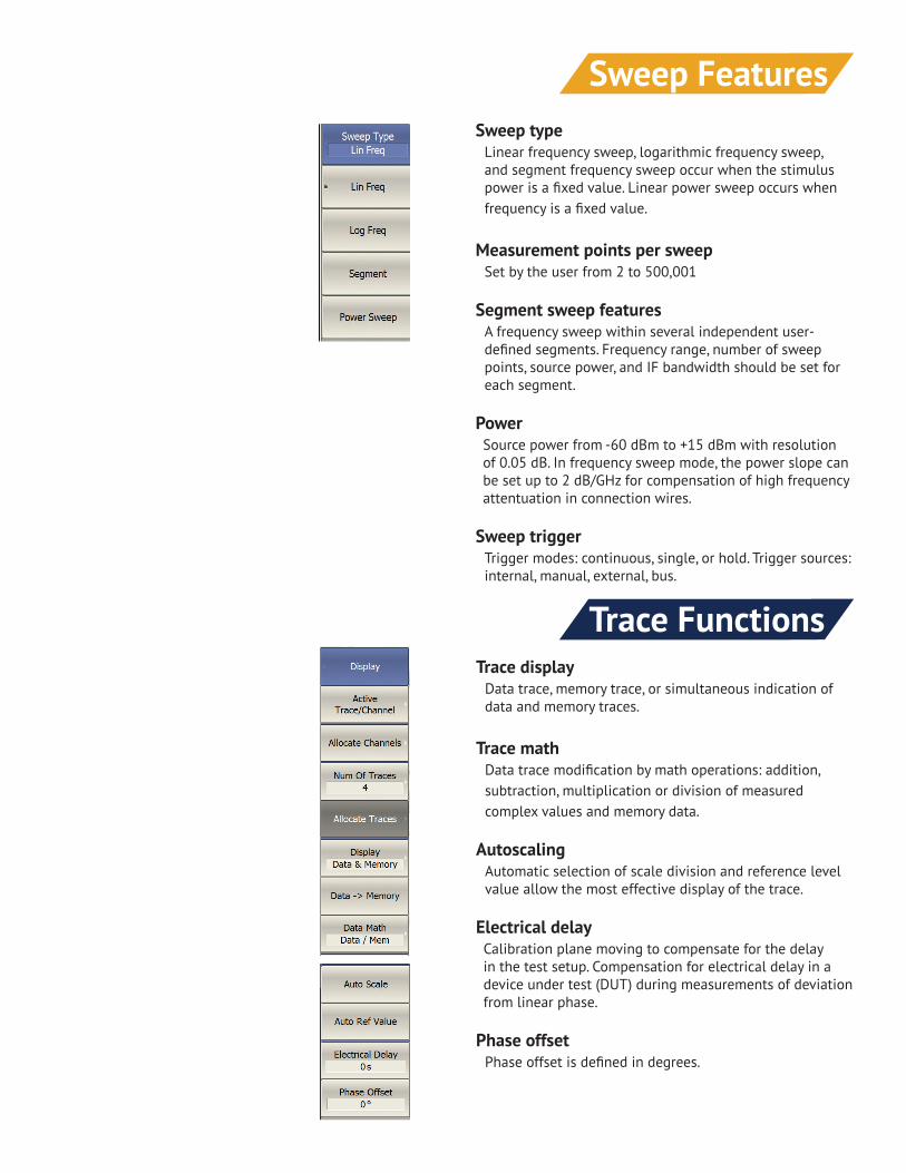
Sweep typeLinear frequency sweep, logarithmic frequency sweep, and segment frequency sweep occur when the stimulus power is a fixed value. Linear power sweep occurs when frequency is a fixed value.
Measurement points per sweepSet by the user from 2 to 500,001
Segment sweep featuresA frequency sweep within several independent user-defined segments. Frequency range, number of sweep points, source power, and IF bandwidth should be set for each segment.
PowerSource power from -60 dBm to +15 dBm with resolution of 0.05 dB. In frequency sweep mode, the power slope can be set up to 2 dB/GHz for compensation of high frequency attentuation in connection wires.
Sweep triggerTrigger modes: continuous, single, or hold. Trigger sources: internal, manual, external, bus.
Sweep Features
Trace displayData trace, memory trace, or simultaneous indication of data and memory traces.
Trace mathData trace modification by math operations: addition, subtraction, multiplication or division of measured complex values and memory data.
AutoscalingAutomatic selection of scale division and reference level value allow the most effective display of the trace.
Electrical delayCalibration plane moving to compensate for the delay in the test setup. Compensation for electrical delay in a device under test (DUT) during measurements of deviation from linear phase.
Phase offsetPhase offset is defined in degrees.
Trace Functions

Scalar mixer/converter measurementsThe scalar method allows the user to measure only the magnitude of the transmission coefficient of the mixer and other frequency translating devices. No external mixers or other devices are required. The scalar method employs port frequency offset when there is a difference between the source port frequency and the receiver port frequency.
Scalar mixer/converter calibrationThis is the most accurate method of calibration applied for measurements of mixers in frequency offset mode. The SHORT, OFFSET SHORT and LOAD calibration standards are used.
Vector mixer/converter measurementsThe vector method allows the measurement of both the magnitude and phase of the mixer transmission coefficient. This method requires an external mixer and an LO common for both the external mixer and the mixer under test.
Vector mixer/converter calibrationThis method of calibration is applied for vector mixer measurements. OPEN, SHORT, and LOAD calibration standards are used.
Automatic frequency offset adjustmentThis function performs automatic frequency offset adjustment when the scalar mixer/converter measurements are performed to compensate for internal LO setting inaccuracy in the DUT.
Mixer/Converter Measurements
Frequency scan segmentationThe VNA has a large frequency range with the option of frequency scan segmentation. This allows optimal use of the device, for example, to realize the maximum dynamic range while maintaining high measurement speed.
Frequency Scan Segmentation

COM/DCOM compatibleCobalt’s software is COM/DCOM compatible, which allows the unit to be used as a part of an ATE station and other special applications. COM/DCOM automation is used for remote control and data exchange with the user software. The Analyzer program runs as COM/DCOM client. The COM client runs on Analyzer PC. The DCOM client run on a separate PC connected via LAN.
LabView compatibleThe device and its software are fully compatible with LabView applications, for ultimate flexibility in user-generated programming and automation.
Time domain measurementsThis function performs data transmission from frequency domain into response of the DUT to various stimulus types in time domain. Modeled stimulus types: bandpass, lowpass impulse, and lowpass step. Time domain span is set by the user arbitrarily from zero to maximum, which is determined by the frequency step. Windows of various forms are used for better tradeoff between resolution and level of spurious sidelobes.
Here, built in time domain analysis allows the user to detect a physical impairment in a cable.
Time domain analysis allows measurements of parameters of SAW filters such as the signal time delay, feedthrough signal suppression.
Measurement Automation
Time domain gatingThis function mathematically removes unwanted responses in the time domain, which allows the user to obtain frequency response without influence from fixture elements.
This function applies reverse transformation back to the frequency domain after cutting out the user-defined span in time domain. Gating filter types: bandpass or notch. For a better tradeoff between gate resolution and level of spurious sidelobes the following filter shapes are available: maximum, wide, normal and minimum.
Applications of these features include, but are not limited to: measurements of SAW filter parameters, such as filter time delay or forward transmission attenuation.
Time Domain Measurements
Time Domain Gating

Embedding
De-Embedding
EmbeddingThis function allows the user to mathematically simulate DUT parameters by virtually integrating a fixture circuit between the calibration plane and the DUT. This circuit should be described by an S-parameter matrix in a Touchstone file.
De-EmbeddingThis function allows the user to mathematically exclude the effects of the fixture circuit connected between the calibration plane and the DUT from the measurement results. This circuit should be described by an S-parameter matrix in a Touchstone file.

Limit TestingLimit testing
Limit testing is a function of automatic pass/fail judgement for the trace of the measurement results. The judgement is based on the comparison of the trace to the limit line set by the user and can consist of one or several segments.
Each segment checks the measurement value for failing either the upper or lower limit, or both. The limit line segment is defined by specifying the coordinates of the beginning (X0, Y0) and the end (X1, Y1) of the segment, and type of the limit. The MAX or MIN limit types check if the trace falls outside of the upper or lower limit, respectively.

Port Impedance Conversion
S-Parameter Conversion
Port impedance conversionThis function of conversion of the S-parameters measured at 50 Ω port into the values, which could be determined if measured at a test port with arbitrary impedance.
S-parameter conversionThe function allows conversion of the measured S-parameters to the following parameters: reflection impedance and admittance, transmission impedance and admittance, and inverse S-parameters

Data Output
Analyzer StateAll state, calibration and measurement data can be saved to an Analyzer state file on the hard disk and later uploaded back into the software program. The following four types of saving are available: State, State & Cal, Stat & Trace, or All.
Channel StateA channel state can be saved into tha Analyzer memory. The channel state saving procedure is similar to saving of the Analyzer state saving, and the same saving types are applied to the channel state saving. Unlike the Analyzer state, the channel state is saved into the Analyzer inner volatile memory (not to the hard disk) and is cleared when the power to the Analyzer is turned off. For channel state storage, there are four memory registers A, B, C, D. The channel state saving allows the user to easily copy the settings of one channel to another one.
Trace Data CSV FileThe Analyzer allows the use to save an individual trace data as a CSV file (comma separated values). The active trace stimulus and response values in current format are saved to *.CSV file. Only one trace data are saved to the file.
Trace Data Touchstone FileThe Analyzer allows the user to save S-parameters to a Touchstone file. The Touchstone file contains the frequency values and S-parameters. The files of this format are typical for most of circuit simluator programs. The *.s2p files are used for saving all the four S-parameters of a 2-port device. The *.s1p files are used for saving S11 and S22 parameters of a 1-port device. Only one (active) trace data are saved to the file. The Touchstone file saving function is applied to individual active channels.
Screenshot captureThe print function is provided with the preview feature, which allows the user to view the image to be printed on the screen, and/or save it to a file. Screenshots can be printed using three different applications: MS Word, Image Viewer for Windows, or the Print Wizard of the Analyzer. Each screenshot can be printed in color, grayscale, black and white, or inverted for visibility or ink use. The current date and time can be added to each capture before it is transferred to the printing application, resulting in wuick and easy test reporting.

Typical Output Power Plots
0
1
2
3
4
5
6
7
8
9
10
60 62.5 65 67.5 70 72.5 75 77.5 80 82.5 85 87.5 90
Out
put P
ower
[dB
m]
RF Frequency [GHz]
Output Power vs Frequency
2
3
4
5
6
7
8
9
10
75 77.5 80 82.5 85 87.5 90 92.5 95 97.5 100 102.5 105 107.5 110
Out
put P
ower
[dB
m]
RF Frequency [GHz]
Output Power vs Frequency
0123456789
101112
50 52.5 55 57.5 60 62.5 65 67.5 70 72.5 75
Out
put P
ower
[dB
m]
RF Frequency [GHz]
Output Power vs FrequencyCobaltFx 15
CobaltFx 12
CobaltFx 10

CalibrationCalibration of a test setup (which includes the VNA, cables, and adapters) significantly increases the accuracy of measurements. Calibration allows for correction of the errors caused by imperfections in the measurement system: system directivity, source and load match, tracking and isolation.
Calibration methodsThe following calibration methods of various sophistication and accuracy enhancement level are available:• reflection and transmission normalization• full one-port calibration• one-path two-port calibration• full two-port calibration
Reflection and transmission normalizationThis is the simplest calibration method; however, it provides reasonably low accuracy compared to other methods.
Full one-port calibrationMethod of calibration performed for one-port reflection measurements. It ensures high accuracy.
One-path two-port calibrationMethod of calibration performed for reflection and one-way transmission measurements, for example for measuring S11 and S21 only. It ensures high accuracy for reflection measurements, and mean accuracy for transmission measurements.
Full two-port calibrationThis method of calibration is performed for fill S-parameter matrix measurement of a two-port DUT, ensuring high accuracy.
DescriptionThe FEK-15-0006, FEK-12-0006 and FEK-10-0006 calibration kits provide accurate calibration of the CobaltFx millimeter wave measuremet system in WR-15, WR-12 and WR-10 bands respectively. They are compatible with TRL and SOLT calibration techniques
Features• Ensures accurate and repeatable measurements • Contains characterisation data for the kit components in a suitable format for the VNA
Applications• Millimeter wave S-parameter measurements that require system error correction
Waveguide Calibration KitsSpecification
Unit Min Typ Max Unit Min Typ Max Unit Min Typ MaxOperating Frequency Range GHz 50 75 GHz 60 90 GHz 75 110
Waveguide Designation
Flange Type
Cut Off Frequency GHz GHz GHzFixed Load VSWR
Flush Short Flatness mm mm mmOperating Temperature Range °C +20 +30 °C +20 +30 °C +20 +30
ContentBroadband Termination
Flush Short1/4 Lambda Offset
AccessoriesHex Driver 5/64" A/FFlange Screws - ShortFlange Screws - Long
Alignment PinsUSB Flash Memory
Note:
General Data: Waveguide Calibration KitsFEK-15-0006 FEK-12-0006 FEK-10-0006
WR-10, WG-27
<1.04:1<0.012
WR-12, WG-26
IEEE 1785-2a (Precision style)
48.3692<1.04:1<0.012
IEEE 1785-2a (Precision style)
59.0143
<0.016<1.035:139.8765
IEEE 1785-2a (Precision style)
WR-15, WG-25
4 off1 off
Quantity Quantity1 off1 off1 off
1 off1 off1 off
Quantity
4 off4 off1 off
Farran Technology reserves the right to change, without notice, the characteristic data and other specifications applied to this product. The product may be subject to Irish export restrictions.
1 off1 off1 off
1 off4 off
1 off4 off4 off4 off1 off
1 off4 off4 off

Technical Specifications
SpecificationUnit Min Typ Max Unit Min Typ Max Unit Min Typ Max
System Operating Frequency GHz 50 75 GHz 60 90 GHz 75 110Test Port Output Power dBm +5 +8 dBm +2 +5 dBm 0 +5
System Dynamic Range (2) dB 110 120 dB 100 110 dB 100 110Raw Coupler Directivity dB 40 45 dB 40 45 dB 40 45
Trace Stability Magnitude (3) dB ±0.2 dB ±0.2 dB ±0.2Trace Stability Phase (3) degree 2 degree 2 degree 2
Test Port Input 0.1dB Compression Point
dBm +15 dBm +15 dBm +10
RF Input Frequency GHz 6.25 9.375 GHz 5 7.5 GHz 6.25 9.17RF Input Power dBm 0 dBm 0 dBm 0
LO Input Frequency GHz 4.17 6.25 GHz 5 7.5 GHz 4.688 6.875LO Input Power dBm 0 dBm 0 dBm 0
IF Output Frequency MHz 7.5 MHz 7.5 MHz 7.5Test Port Damage Level dBm +20 dBm +20 dBm +20
RF/LO Port Damage Level dBm +10 dBm +10 dBm +10
Test Port Interface - - -
RF/LO/IF Connector - - -DC Power Requirements - - -
Weight kg 3.5 kg 3.5 kg 3.5Dimensions (L x W x H) - - -Operating Temperatures °C 0 30 °C 0 30 °C 0 30
(1)
(2)
(3)
General Data: ExtendersCobaltFx 15 CobaltFx 12 CobaltFx 10
WR-10 IEEE 1785-2a compatible with UG-
387/UM
WR-15 IEEE 1785-2a compatible with UG-385/U
SMA (F)+6V at 2200 mA
220 x 105 x 80
WR-12 IEEE 1785-2a compatible with UG-387/U
SMA (F)+6V at 2200 mA
220 x 105 x 80
Measured at 1h after 1h warm up and calibration. Assuming ideal RF and LO cables.
SMA (F)+6V at 2200 mA
220 x 105 x 80
Specifications are typical and subject to change without a notice.
Measured at 10 Hz of IF bandwidth.

Accuracy Enhancement
SpecificationUnit Min Typ Max Unit Min Typ Max Unit Min Typ Max
System Operating Frequency GHz 50 75 GHz 60 90 GHz 75 110Test Port Output Power dBm +5 +8 dBm +2 +5 dBm 0 +5
System Dynamic Range (2) dB 110 120 dB 100 110 dB 100 110Raw Coupler Directivity dB 40 45 dB 40 45 dB 40 45
Trace Stability Magnitude (3) dB ±0.2 dB ±0.2 dB ±0.2Trace Stability Phase (3) degree 2 degree 2 degree 2
Test Port Input 0.1dB Compression Point
dBm +15 dBm +15 dBm +10
RF Input Frequency GHz 6.25 9.375 GHz 5 7.5 GHz 6.25 9.17RF Input Power dBm 0 dBm 0 dBm 0
LO Input Frequency GHz 4.17 6.25 GHz 5 7.5 GHz 4.688 6.875LO Input Power dBm 0 dBm 0 dBm 0
IF Output Frequency MHz 7.5 MHz 7.5 MHz 7.5Test Port Damage Level dBm +20 dBm +20 dBm +20
RF/LO Port Damage Level dBm +10 dBm +10 dBm +10
Test Port Interface - - -
RF/LO/IF Connector - - -DC Power Requirements - - -
Weight kg 3.5 kg 3.5 kg 3.5Dimensions (L x W x H) - - -Operating Temperatures °C 0 30 °C 0 30 °C 0 30
(1)
(2)
(3)
General Data: ExtendersCobaltFx 15 CobaltFx 12 CobaltFx 10
WR-10 IEEE 1785-2a compatible with UG-
387/UM
WR-15 IEEE 1785-2a compatible with UG-385/U
SMA (F)+6V at 2200 mA
220 x 105 x 80
WR-12 IEEE 1785-2a compatible with UG-387/U
SMA (F)+6V at 2200 mA
220 x 105 x 80
Measured at 1h after 1h warm up and calibration. Assuming ideal RF and LO cables.
SMA (F)+6V at 2200 mA
220 x 105 x 80
Specifications are typical and subject to change without a notice.
Measured at 10 Hz of IF bandwidth.
(1) Specifications are typical and subject to change without a notice(2) Measured at 10 Hz of IF bandwidth(3) Measured at 1h after 1h warm up and calibration. Assuming ideal RF and LO cables.

631 E. New York St.Indianapolis, IN 46202
USAUSA: +1.317.222.5400
www.coppermountaintech.com
Unit 1, Airport East Business ParkFarmers CrossCork, Co. Cork
IrelandIRL: +353 21 484 9170
www.farran.com