extended detention basin (edb) t-5 -...
TRANSCRIPT
Extended Detention Basin (EDB) T-5
December 2010 Urban Drainage and Flood Control District EDB-1 Urban Storm Drainage Criteria Manual Volume 3
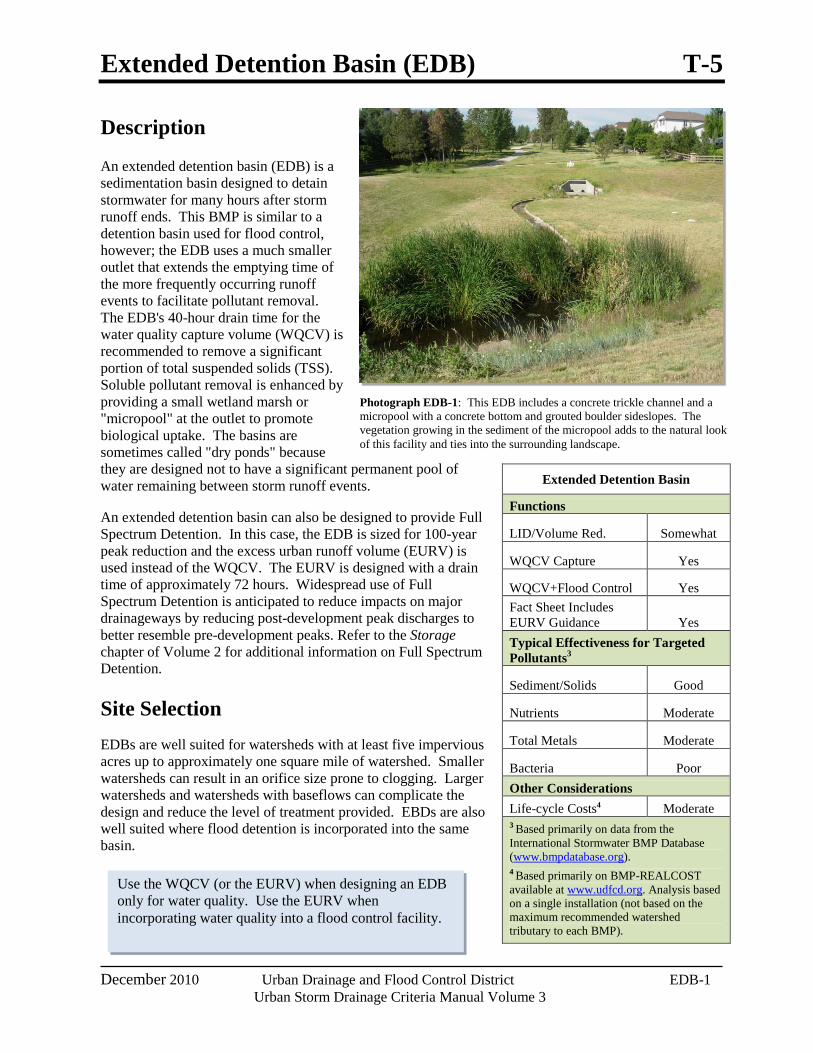
Photograph EDB-1: This EDB includes a concrete trickle channel and a micropool with a concrete bottom and grouted boulder sideslopes. The vegetation growing in the sediment of the micropool adds to the natural look of this facility and ties into the surrounding landscape.
Use the WQCV (or the EURV) when designing an EDB only for water quality. Use the EURV when incorporating water quality into a flood control facility.
Description
An extended detention basin (EDB) is a sedimentation basin designed to detain stormwater for many hours after storm runoff ends. This BMP is similar to a detention basin used for flood control, however; the EDB uses a much smaller outlet that extends the emptying time of the more frequently occurring runoff events to facilitate pollutant removal. The EDB's 40-hour drain time for the water quality capture volume (WQCV) is recommended to remove a significant portion of total suspended solids (TSS). Soluble pollutant removal is enhanced by providing a small wetland marsh or "micropool" at the outlet to promote biological uptake. The basins are sometimes called "dry ponds" because they are designed not to have a significant permanent pool of water remaining between storm runoff events.
An extended detention basin can also be designed to provide Full Spectrum Detention. In this case, the EDB is sized for 100-year peak reduction and the excess urban runoff volume (EURV) is used instead of the WQCV. The EURV is designed with a drain time of approximately 72 hours. Widespread use of Full Spectrum Detention is anticipated to reduce impacts on major drainageways by reducing post-development peak discharges to better resemble pre-development peaks. Refer to the Storage chapter of Volume 2 for additional information on Full Spectrum Detention.
Site Selection EDBs are well suited for watersheds with at least five impervious acres up to approximately one square mile of watershed. Smaller watersheds can result in an orifice size prone to clogging. Larger watersheds and watersheds with baseflows can complicate the design and reduce the level of treatment provided. EBDs are also well suited where flood detention is incorporated into the same basin.
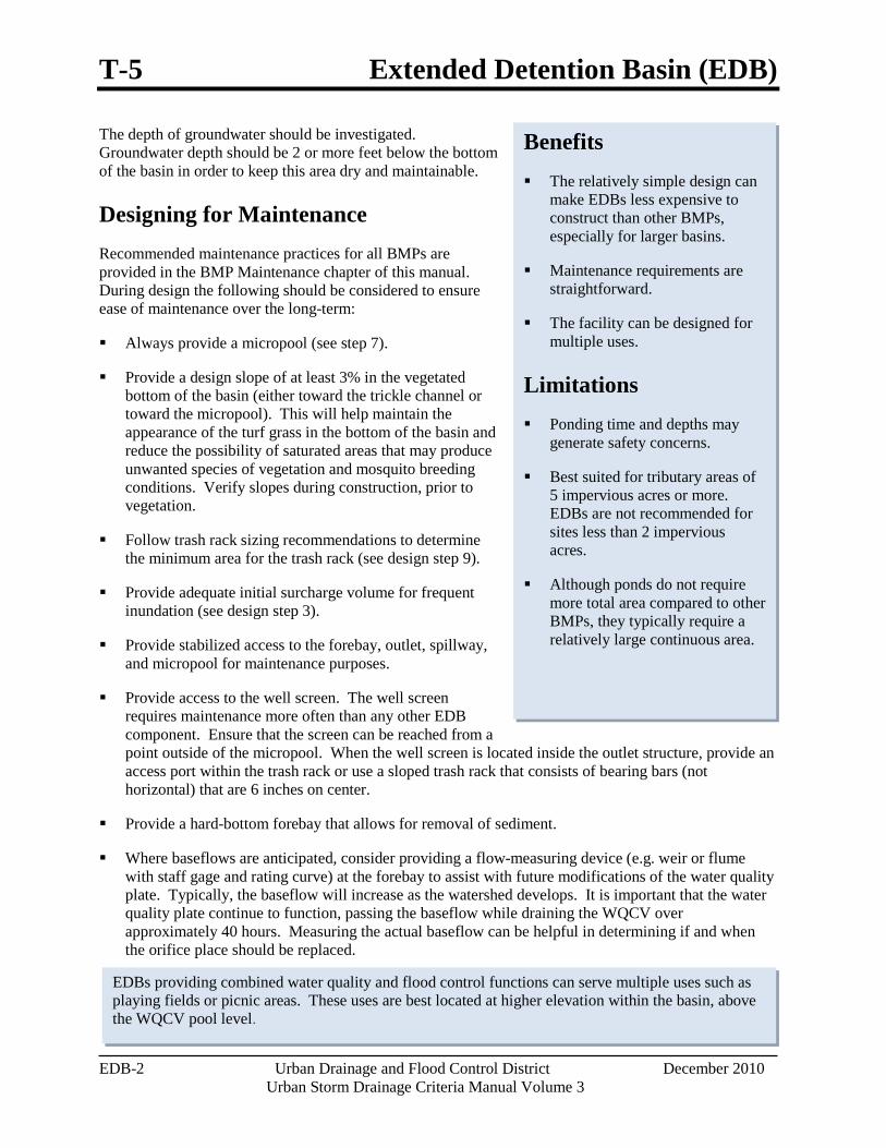
Extended Detention Basin
Functions
LID/Volume Red. Somewhat
WQCV Capture Yes
WQCV+Flood Control Yes Fact Sheet Includes EURV Guidance Yes Typical Effectiveness for Targeted Pollutants3
Sediment/Solids Good
Nutrients Moderate
Total Metals Moderate
Bacteria Poor Other Considerations Life-cycle Costs4 Moderate 3 Based primarily on data from the International Stormwater BMP Database (www.bmpdatabase.org). 4 Based primarily on BMP-REALCOST available at www.udfcd.org. Analysis based on a single installation (not based on the maximum recommended watershed tributary to each BMP).
T-5 Extended Detention Basin (EDB)
EDB-2 Urban Drainage and Flood Control District December 2010 Urban Storm Drainage Criteria Manual Volume 3
Benefits The relatively simple design can
make EDBs less expensive to construct than other BMPs, especially for larger basins.
Maintenance requirements are straightforward.
The facility can be designed for multiple uses.
Limitations Ponding time and depths may
generate safety concerns.
Best suited for tributary areas of 5 impervious acres or more. EDBs are not recommended for sites less than 2 impervious acres.
Although ponds do not require more total area compared to other BMPs, they typically require a relatively large continuous area.
EDBs providing combined water quality and flood control functions can serve multiple uses such as playing fields or picnic areas. These uses are best located at higher elevation within the basin, above the WQCV pool level.
The depth of groundwater should be investigated. Groundwater depth should be 2 or more feet below the bottom of the basin in order to keep this area dry and maintainable.
Designing for Maintenance Recommended maintenance practices for all BMPs are provided in the BMP Maintenance chapter of this manual. During design the following should be considered to ensure ease of maintenance over the long-term:
Always provide a micropool (see step 7).
Provide a design slope of at least 3% in the vegetated bottom of the basin (either toward the trickle channel or toward the micropool). This will help maintain the appearance of the turf grass in the bottom of the basin and reduce the possibility of saturated areas that may produce unwanted species of vegetation and mosquito breeding conditions. Verify slopes during construction, prior to vegetation.
Follow trash rack sizing recommendations to determine the minimum area for the trash rack (see design step 9).
Provide adequate initial surcharge volume for frequent inundation (see design step 3).
Provide stabilized access to the forebay, outlet, spillway, and micropool for maintenance purposes.
Provide access to the well screen. The well screen requires maintenance more often than any other EDB component. Ensure that the screen can be reached from a point outside of the micropool. When the well screen is located inside the outlet structure, provide an access port within the trash rack or use a sloped trash rack that consists of bearing bars (not horizontal) that are 6 inches on center.
Provide a hard-bottom forebay that allows for removal of sediment.
Where baseflows are anticipated, consider providing a flow-measuring device (e.g. weir or flume with staff gage and rating curve) at the forebay to assist with future modifications of the water quality plate. Typically, the baseflow will increase as the watershed develops. It is important that the water quality plate continue to function, passing the baseflow while draining the WQCV over approximately 40 hours. Measuring the actual baseflow can be helpful in determining if and when the orifice place should be replaced.
Extended Detention Basin (EDB) T-5
December 2010 Urban Drainage and Flood Control District EDB-3 Urban Storm Drainage Criteria Manual Volume 3
Design Procedure and Criteria
The following steps outline the design procedure and criteria for an EDB:
1. Basin Storage Volume: Provide a design volume equal to 120% of the WQCV or 100% of the EURV. This volume begins at the lowest orifice in the outlet structure. The additional 20% for the WQCV is for sediment accumulation and the resultant loss in storage volume. Additional volume for sediment storage is not necessary when designing for the EURV, as the water quality perforations extend above the depth of the WQCV.
Determine the imperviousness of the watershed (or effective imperviousness where LID elements are used upstream).
Find the required storage volume. Determine the required WQCV or EURV (watershed inches of runoff) using Figure 3-2 located in Chapter 3 of this manual (for WQCV) or equations provided in the Storage chapter of Volume 2 (for EURV).
Calculate the design volume as follows:
𝑉𝑉 = �WQCV
12 �1.2 𝐴𝐴
For WQCV: Equation EDB-1
𝑉𝑉 = �EURV
12 � 𝐴𝐴
For EURV: Equation EDB-2
Where:
V = design volume (acre ft)
A = watershed area tributary to the extended detention basin (acres)
1.2 factor = multiplier to accommodate sediment accumulation
2. Basin Shape: Always maximize the distance between the inlet and the outlet. It is best to have a basin length (measured along the flow path from inlet to outlet) to width ratio of at least 2:1. A longer flow path from inlet to outlet will minimize short circuiting and improve reduction of TSS. To achieve this ratio, it may be necessary to modify the inlet and outlet points through the use of pipes or swales.
3. Basin Side Slopes: Basin side slopes should be stable and gentle to facilitate maintenance and access. Slopes that are 4:1or flatter should be used to allow for conventional maintenance equipment and for improved safety, maintenance, and aesthetics. Side slopes should be no steeper than 3:1. The use of walls is highly discouraged due to maintenance constraints.
4. Inlet: Dissipate flow energy at concentrated points of inflow. This will limit erosion and promote particle sedimentation. Inlets should be designed in accordance with UDFCD drop structure criteria
T-5 Extended Detention Basin (EDB)
EDB-4 Urban Drainage and Flood Control District December 2010 Urban Storm Drainage Criteria Manual Volume 3
for inlets above the invert of the forebay, impact basin outlet details for at grade inlets, or other types of energy dissipating structures.
5. Forebay Design: The forebay provides an opportunity for larger particles to settle out in an area that can be easily maintained. The length of the flow path through the forebay should be maximized, and the slope minimized to encourage settling. The appropriate size of the forebay may be as much a function of the level of development in the tributary area as it is a percentage of the WQCV. When portions of the watershed may remain disturbed for an extended period of time, the forebay size will need to be increased due to the potentially high sediment load. Refer to Table EDB-4 for a design criteria summary. When using this table, the designer should consider increasing the size of the forebay if the watershed is not fully developed.
The forebay outlet should be sized to release 2% of the undetained peak 100-year discharge. A soil riprap berm with 3:1 sideslopes (or flatter) and a pipe outlet or a concrete wall with a notch outlet should be constructed between the forebay and the main EDB. It is recommended that the berm/pipe configuration be reserved for watersheds in excess of 20 impervious acres to accommodate the minimum recommended pipe diameter of 8 inches. When using the berm/pipe configuration, round up to the nearest standard pipe size and use a minimum diameter of 8 inches. The floor of the forebay should be concrete or lined with grouted boulders to define sediment removal limits. With either configuration, soil riprap should also be provided on the downstream side of the forebay berm or wall if the downstream grade is lower than the top of the berm or wall. The forebay will overtop frequently so this protection is necessary for erosion control. All soil riprap in the area of the forebay should be seeded and erosion control fabric should be placed to retain the seed in this high flow area.
6. Trickle Channel: Convey low flows from the forebay to the micropool with a trickle channel. The trickle channel should have a minimum flow capacity equal to the maximum release from the forebay outlet.
Concrete Trickle Channels: A concrete trickle channel will help to establish the bottom of the basin long-term and may also facilitate regular sediment removal. It can be a "V" shaped concrete drain pan or a concrete channel with curbs. A flat-bottom channel facilitates maintenance. A slope between 0.4% - 1% is recommended to encourage settling while reducing the potential for low points within the pan.
Soft-bottom Trickle Channels: When designed and maintained properly, soft-bottom trickle channels can allow for an attractive alternative to concrete. They can also improve water quality. However, they are not appropriate for all sites. Be aware, maintenance of soft bottom trickle channels requires mechanical removal of sediment and vegetation. Additionally, this option provides mosquito habitat. For this reason, UDFCD recommends that they be considered on a case-by-case basis and with the approval of the local jurisdiction. It is recommended that soft bottom trickle channels be designed with a consistent longitudinal slope from forebay to micropool and that they not meander. This geometry will allow for reconstruction of the original design when sediment removal in the trickle channel is necessary. The trickle channel may also be located along the toe of the slope if a straight channel is not desired. The recommended minimum depth of a soft bottom trickle channel is 1.5 feet. This depth will help limit potential wetland growth to the trickle channel, preserving the bottom of the basin.
Riprap and soil riprap lined trickle channels are not recommended due to past maintenance experiences, where the riprap was inadvertently removed along with the sediment during maintenance.
Extended Detention Basin (EDB) T-5
December 2010 Urban Drainage and Flood Control District EDB-5 Urban Storm Drainage Criteria Manual Volume 3
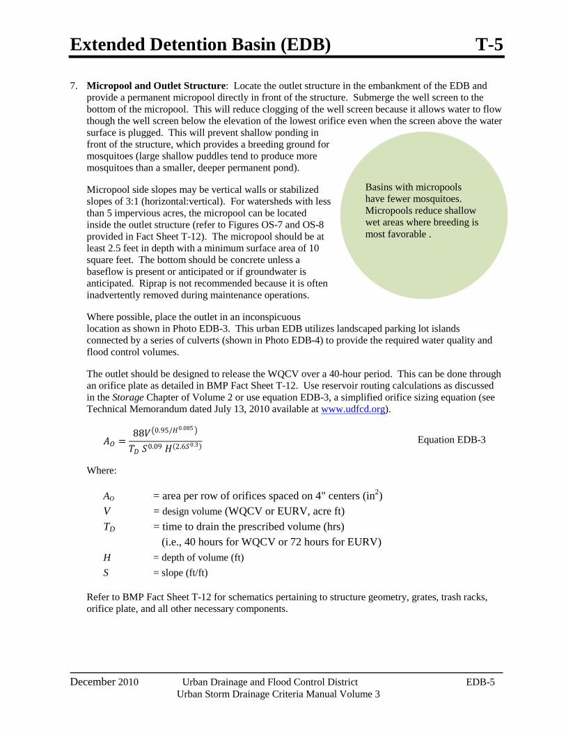
Basins with micropools have fewer mosquitoes. Micropools reduce shallow wet areas where breeding is most favorable .
7. Micropool and Outlet Structure: Locate the outlet structure in the embankment of the EDB and provide a permanent micropool directly in front of the structure. Submerge the well screen to the bottom of the micropool. This will reduce clogging of the well screen because it allows water to flow though the well screen below the elevation of the lowest orifice even when the screen above the water surface is plugged. This will prevent shallow ponding in front of the structure, which provides a breeding ground for mosquitoes (large shallow puddles tend to produce more mosquitoes than a smaller, deeper permanent pond).
Micropool side slopes may be vertical walls or stabilized slopes of 3:1 (horizontal:vertical). For watersheds with less than 5 impervious acres, the micropool can be located inside the outlet structure (refer to Figures OS-7 and OS-8 provided in Fact Sheet T-12). The micropool should be at least 2.5 feet in depth with a minimum surface area of 10 square feet. The bottom should be concrete unless a baseflow is present or anticipated or if groundwater is anticipated. Riprap is not recommended because it is often inadvertently removed during maintenance operations.
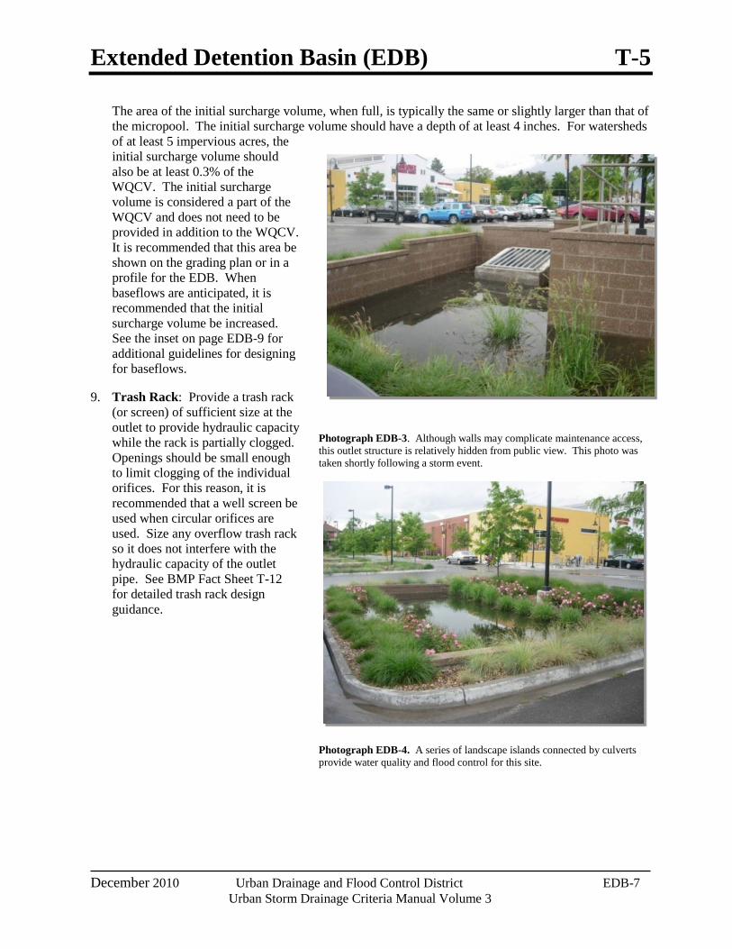
Where possible, place the outlet in an inconspicuous location as shown in Photo EDB-3. This urban EDB utilizes landscaped parking lot islands connected by a series of culverts (shown in Photo EDB-4) to provide the required water quality and flood control volumes.
The outlet should be designed to release the WQCV over a 40-hour period. This can be done through an orifice plate as detailed in BMP Fact Sheet T-12. Use reservoir routing calculations as discussed in the Storage Chapter of Volume 2 or use equation EDB-3, a simplified orifice sizing equation (see Technical Memorandum dated July 13, 2010 available at www.udfcd.org).
𝐴𝐴𝑂𝑂 =88𝑉𝑉�0.95/𝐻𝐻0.085 �
𝑇𝑇𝐷𝐷 𝑆𝑆0.09 𝐻𝐻(2.6𝑆𝑆0.3) Equation EDB-3
Where:
AO = area per row of orifices spaced on 4" centers (in2) V = design volume (WQCV or EURV, acre ft) TD = time to drain the prescribed volume (hrs) (i.e., 40 hours for WQCV or 72 hours for EURV) H = depth of volume (ft) S = slope (ft/ft)
Refer to BMP Fact Sheet T-12 for schematics pertaining to structure geometry, grates, trash racks, orifice plate, and all other necessary components.
T-5 Extended Detention Basin (EDB)
EDB-6 Urban Drainage and Flood Control District December 2010 Urban Storm Drainage Criteria Manual Volume 3
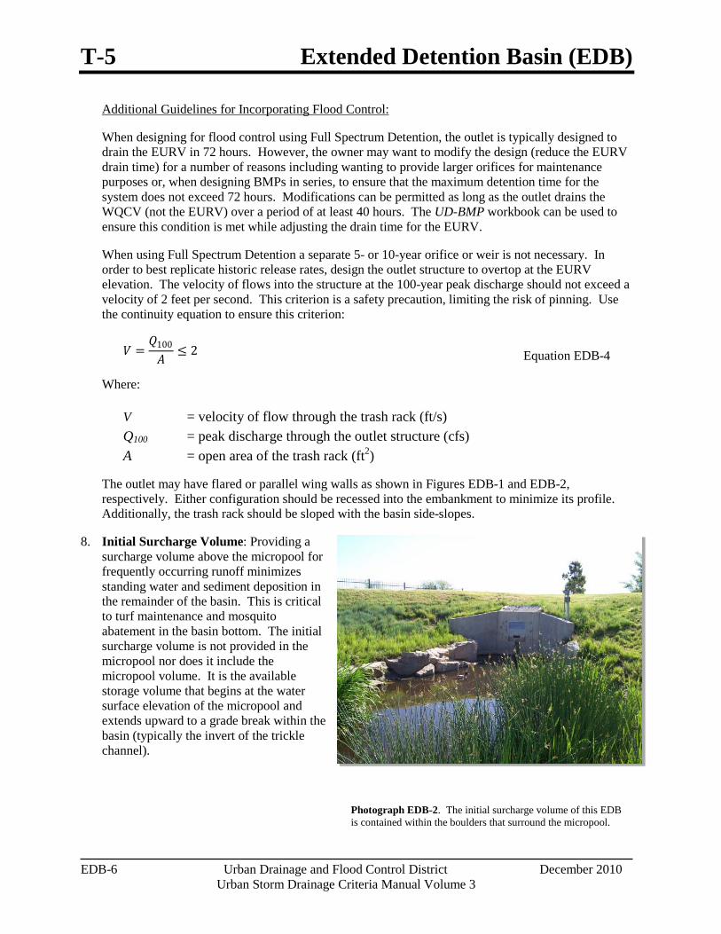
Photograph EDB-2. The initial surcharge volume of this EDB is contained within the boulders that surround the micropool.
When using Full Spectrum Detention a separate 5- or 10-year orifice or weir is not necessary. In order to best replicate historic release rates, design the outlet structure to overtop at the EURV elevation. The velocity of flows into the structure at the 100-year peak discharge should not exceed a velocity of 2 feet per second. This criterion is a safety precaution, limiting the risk of pinning. Use the continuity equation to ensure this criterion:
Additional Guidelines for Incorporating Flood Control:
When designing for flood control using Full Spectrum Detention, the outlet is typically designed to drain the EURV in 72 hours. However, the owner may want to modify the design (reduce the EURV drain time) for a number of reasons including wanting to provide larger orifices for maintenance purposes or, when designing BMPs in series, to ensure that the maximum detention time for the system does not exceed 72 hours. Modifications can be permitted as long as the outlet drains the WQCV (not the EURV) over a period of at least 40 hours. The UD-BMP workbook can be used to ensure this condition is met while adjusting the drain time for the EURV.
𝑉𝑉 =𝑄𝑄100
𝐴𝐴≤ 2 Equation EDB-4
Where:
V = velocity of flow through the trash rack (ft/s) Q100 = peak discharge through the outlet structure (cfs) A = open area of the trash rack (ft2)
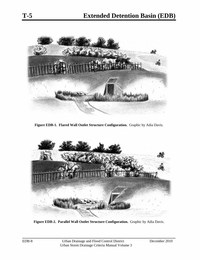
The outlet may have flared or parallel wing walls as shown in Figures EDB-1 and EDB-2, respectively. Either configuration should be recessed into the embankment to minimize its profile. Additionally, the trash rack should be sloped with the basin side-slopes.
8. Initial Surcharge Volume: Providing a surcharge volume above the micropool for frequently occurring runoff minimizes standing water and sediment deposition in the remainder of the basin. This is critical to turf maintenance and mosquito abatement in the basin bottom. The initial surcharge volume is not provided in the micropool nor does it include the micropool volume. It is the available storage volume that begins at the water surface elevation of the micropool and extends upward to a grade break within the basin (typically the invert of the trickle channel).
Extended Detention Basin (EDB) T-5
December 2010 Urban Drainage and Flood Control District EDB-7 Urban Storm Drainage Criteria Manual Volume 3
The area of the initial surcharge volume, when full, is typically the same or slightly larger than that of the micropool. The initial surcharge volume should have a depth of at least 4 inches. For watersheds of at least 5 impervious acres, the initial surcharge volume should also be at least 0.3% of the WQCV. The initial surcharge volume is considered a part of the WQCV and does not need to be provided in addition to the WQCV. It is recommended that this area be shown on the grading plan or in a profile for the EDB. When baseflows are anticipated, it is recommended that the initial surcharge volume be increased. See the inset on page EDB-9 for additional guidelines for designing for baseflows.
9. Trash Rack: Provide a trash rack (or screen) of sufficient size at the outlet to provide hydraulic capacity while the rack is partially clogged. Openings should be small enough to limit clogging of the individual orifices. For this reason, it is recommended that a well screen be used when circular orifices are used. Size any overflow trash rack so it does not interfere with the hydraulic capacity of the outlet pipe. See BMP Fact Sheet T-12 for detailed trash rack design guidance.
Photograph EDB-3. Although walls may complicate maintenance access, this outlet structure is relatively hidden from public view. This photo was taken shortly following a storm event.
Photograph EDB-4. A series of landscape islands connected by culverts provide water quality and flood control for this site.
T-5 Extended Detention Basin (EDB)
EDB-8 Urban Drainage and Flood Control District December 2010 Urban Storm Drainage Criteria Manual Volume 3
Figure EDB-1. Flared Wall Outlet Structure Configuration. Graphic by Adia Davis.
Figure EDB-2. Parallel Wall Outlet Structure Configuration. Graphic by Adia Davis.
Extended Detention Basin (EDB) T-5
December 2010 Urban Drainage and Flood Control District EDB-9 Urban Storm Drainage Criteria Manual Volume 3
Designing for Baseflows
Baseflows should be anticipated for large tributary areas and can be accommodated in a variety of ways. Consider the following:
If water rights are available, consider alternate BMPs such as a constructed wetland pond or retention pond.
Anticipate future modifications to the outlet structure. Following construction, baseflows should be monitored periodically. Intermittent flows can become perennial and perennial flows can increase over time. It may be determined that outlet modifications are necessary long after construction of the BMP is complete.
Design foundation drains and other groundwater drains to bypass the water quality plate directing these drains to a conveyance element downstream of the EDB. This will reduce baseflows and help preserve storage for the WQCV.
When the basin is fully developed and an existing baseflow can be approximated prior to design, the water quality orifices should be increased to drain the WQCV in 40 hours (or EURV in 72 hours) while also draining the baseflow. This requires reservoir routing using an inflow hydrograph that includes the baseflow. The UD-Detention workbook available at www.udfcd.org may be used for this purpose.
Increase the initial surcharge volume of the pond to provide some flexibility when baseflows are known or anticipated. Baseflows are difficult to approximate and will continue to increase as the watershed develops. Increasing the initial surcharge volume will accommodate a broader range of flows.
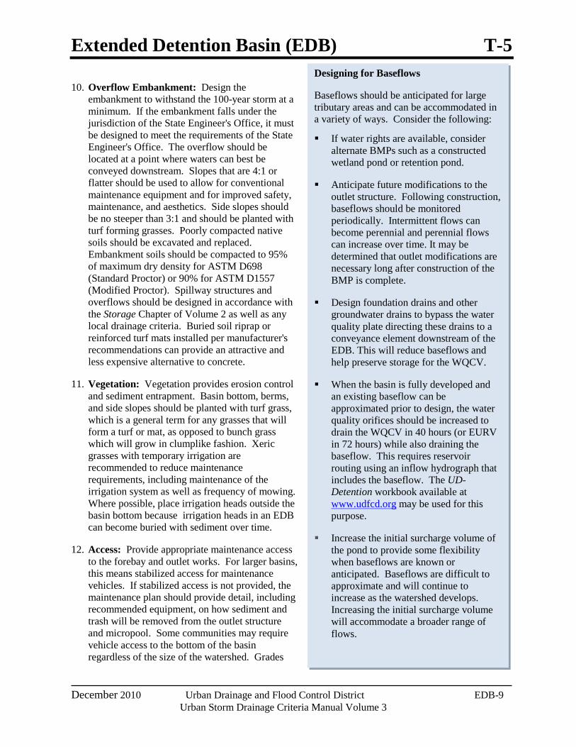
10. Overflow Embankment: Design the embankment to withstand the 100-year storm at a minimum. If the embankment falls under the jurisdiction of the State Engineer's Office, it must be designed to meet the requirements of the State Engineer's Office. The overflow should be located at a point where waters can best be conveyed downstream. Slopes that are 4:1 or flatter should be used to allow for conventional maintenance equipment and for improved safety, maintenance, and aesthetics. Side slopes should be no steeper than 3:1 and should be planted with turf forming grasses. Poorly compacted native soils should be excavated and replaced. Embankment soils should be compacted to 95% of maximum dry density for ASTM D698 (Standard Proctor) or 90% for ASTM D1557 (Modified Proctor). Spillway structures and overflows should be designed in accordance with the Storage Chapter of Volume 2 as well as any local drainage criteria. Buried soil riprap or reinforced turf mats installed per manufacturer's recommendations can provide an attractive and less expensive alternative to concrete.
11. Vegetation: Vegetation provides erosion control and sediment entrapment. Basin bottom, berms, and side slopes should be planted with turf grass, which is a general term for any grasses that will form a turf or mat, as opposed to bunch grass which will grow in clumplike fashion. Xeric grasses with temporary irrigation are recommended to reduce maintenance requirements, including maintenance of the irrigation system as well as frequency of mowing. Where possible, place irrigation heads outside the basin bottom because irrigation heads in an EDB can become buried with sediment over time.
12. Access: Provide appropriate maintenance access to the forebay and outlet works. For larger basins, this means stabilized access for maintenance vehicles. If stabilized access is not provided, the maintenance plan should provide detail, including recommended equipment, on how sediment and trash will be removed from the outlet structure and micropool. Some communities may require vehicle access to the bottom of the basin regardless of the size of the watershed. Grades
T-5 Extended Detention Basin (EDB)
EDB-10 Urban Drainage and Flood Control District December 2010 Urban Storm Drainage Criteria Manual Volume 3
should not exceed 10% for haul road surfaces and 20% for skid-loader and backhoe access. Stabilized access includes gravel, concrete, articulated concrete block, concrete grid pavement, or reinforced grass pavement. The recommended cross slope is 2%.
Aesthetic Design Since all land owners and managers wish to use land in the most efficient manner possible, it is important that EDBs become part of a multi-use system. This encourages the design of EDBs as an aesthetic part of a naturalized environment or to include passive and/or active open space. Within each scenario, the EDB can begin to define itself as more than just a drainage facility. When this happens, the basin becomes a public amenity. This combination of public amenity and drainage facility is of much greater value to a landowner. Softened and varied slopes, interspersed irrigated fields, planting areas and wetlands can all be part of an EDB.
The design should be aesthetic whether it is considered to be an architectural or naturalized basin. Architectural basins incorporate design borrowed or reflective of the surrounding architecture or urban forms. An architectural basin is intended to appear as part of the built environment, rather than hiding the cues that identify it as a stormwater structure. A naturalized basin is designed to appear as though it is a natural part of the landscape. This section provides suggestions for designing a naturalized basin. The built environment, in contrast to the natural environment, does not typically contain the randomness of form inherent in nature. Constructed slopes typically remain consistent, as do slope transitions. Even dissipation structures are usually a hard form and have edges seldom seen in nature. If the EDB is to appear as though it is a natural part of the landscape, it is important to minimize shapes that provide visual cues indicating the presence of a drainage structure. For example, the side sides should be shaped more naturally and with varying slopes for a naturalized basin.
Suggested Methods for a Naturalized Basin
Create a flowing form that looks like it was shaped by water.
Extend one side of the basin higher than the other. This may require a berm.
Shape the bottom of the basin differently than the top.
Slope of one side of the basin more mildly than the opposing side.
Vary slope transitions both at the top of the bank and at the toe.
Use a soft-surface trickle channel if appropriate and approved.
When using rock for energy dissipation, the rock should graduate away from the area of hard edge into the surrounding landscape. Other non-functional matching rock should occur in other areas of the basin to prevent the actual energy dissipation from appearing out of context.
Design ground cover to reflect the type of water regime expected for their location within the basin.
Extended Detention Basin (EDB) T-5
December 2010 Urban Drainage and Flood Control District EDB-11 Urban Storm Drainage Criteria Manual Volume 3
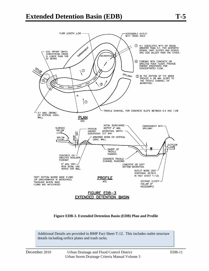
Additional Details are provided in BMP Fact Sheet T-12. This includes outlet structure details including orifice plates and trash racks.
Figure EDB-3. Extended Detention Basin (EDB) Plan and Profile
T-5 Extended Detention Basin (EDB)
EDB-12 Urban Drainage and Flood Control District December 2010 Urban Storm Drainage Criteria Manual Volume 3
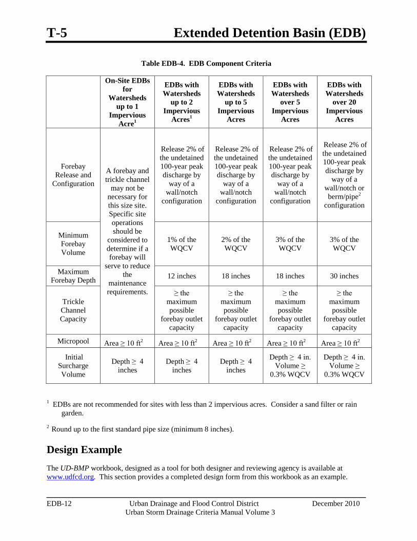
Table EDB-4. EDB Component Criteria
On-Site EDBs for
Watersheds up to 1
Impervious Acre1
EDBs with Watersheds
up to 2 Impervious
Acres1
EDBs with Watersheds
up to 5 Impervious
Acres
EDBs with Watersheds
over 5 Impervious
Acres
EDBs with Watersheds
over 20 Impervious
Acres
Forebay Release and
Configuration A forebay and trickle channel
may not be necessary for this size site. Specific site operations should be
considered to determine if a forebay will
serve to reduce the
maintenance requirements.
Release 2% of the undetained 100-year peak discharge by
way of a wall/notch
configuration
Release 2% of the undetained 100-year peak discharge by
way of a wall/notch
configuration
Release 2% of the undetained 100-year peak discharge by
way of a wall/notch
configuration
Release 2% of the undetained 100-year peak discharge by
way of a wall/notch or berm/pipe2
configuration
Minimum Forebay Volume
1% of the WQCV
2% of the WQCV
3% of the WQCV
3% of the WQCV
Maximum Forebay Depth 12 inches 18 inches 18 inches 30 inches
Trickle Channel Capacity
≥ the maximum possible
forebay outlet capacity
≥ the maximum possible
forebay outlet capacity
≥ the maximum possible
forebay outlet capacity
≥ the maximum possible
forebay outlet capacity
Micropool Area ≥ 10 ft2 Area ≥ 10 ft2 Area ≥ 10 ft2 Area ≥ 10 ft2 Area ≥ 10 ft2
Initial Surcharge Volume
Depth ≥ 4 inches
Depth ≥ 4 inches
Depth ≥ 4 inches
Depth ≥ 4 in. Volume ≥
0.3% WQCV
Depth ≥ 4 in. Volume ≥
0.3% WQCV
1 EDBs are not recommended for sites with less than 2 impervious acres. Consider a sand filter or rain garden.
2 Round up to the first standard pipe size (minimum 8 inches).
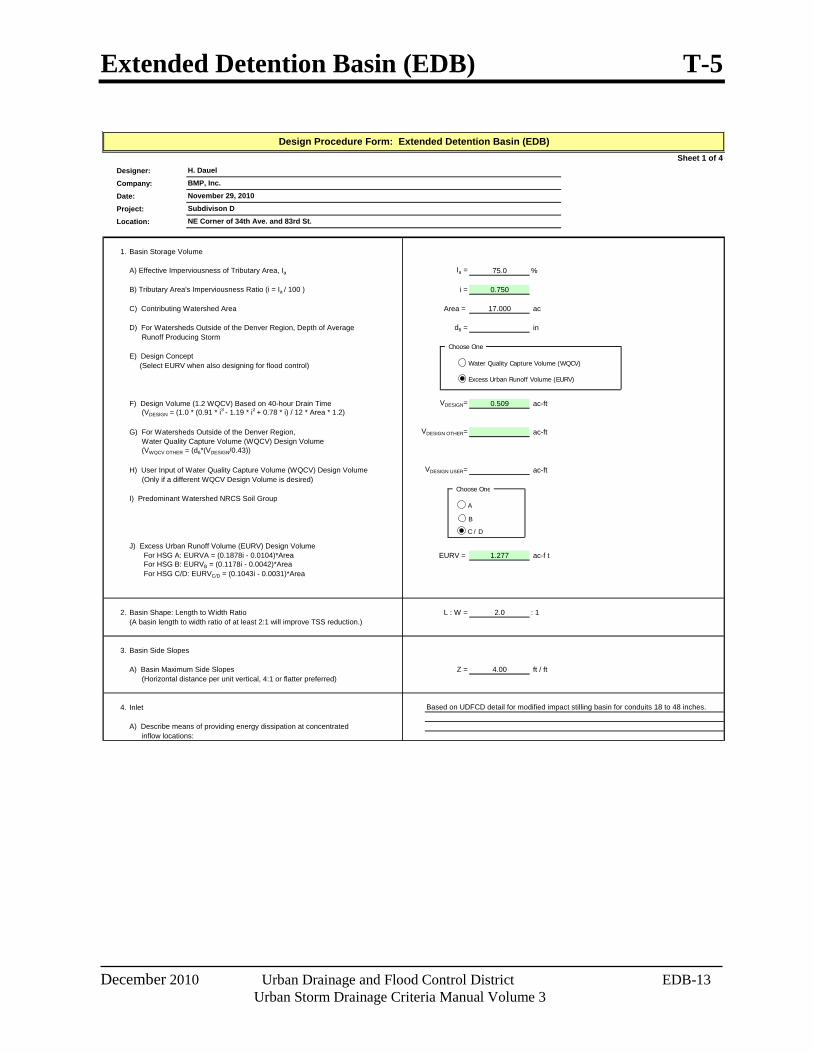
Design Example The UD-BMP workbook, designed as a tool for both designer and reviewing agency is available at www.udfcd.org. This section provides a completed design form from this workbook as an example.
Extended Detention Basin (EDB) T-5
December 2010 Urban Drainage and Flood Control District EDB-13 Urban Storm Drainage Criteria Manual Volume 3
Sheet 1 of 4Designer:
Company:
Date:
Project:
Location:
1. Basin Storage Volume
A) Effective Imperviousness of Tributary Area, Ia Ia = 75.0 %
B) Tributary Area's Imperviousness Ratio (i = Ia / 100 ) i = 0.750
C) Contributing Watershed Area Area = 17.000 ac
D) For Watersheds Outside of the Denver Region, Depth of Average d6 = in Runoff Producing Storm
E) Design Concept (Select EURV when also designing for flood control)
F) Design Volume (1.2 WQCV) Based on 40-hour Drain Time VDESIGN= 0.509 ac-ft (VDESIGN = (1.0 * (0.91 * i3 - 1.19 * i2 + 0.78 * i) / 12 * Area * 1.2)
G) For Watersheds Outside of the Denver Region, VDESIGN OTHER= ac-ft Water Quality Capture Volume (WQCV) Design Volume (VWQCV OTHER = (d6*(VDESIGN/0.43))
H) User Input of Water Quality Capture Volume (WQCV) Design Volume VDESIGN USER= ac-ft (Only if a different WQCV Design Volume is desired)
I) Predominant Watershed NRCS Soil Group
J) Excess Urban Runoff Volume (EURV) Design Volume For HSG A: EURVA = (0.1878i - 0.0104)*Area EURV = 1.277 ac-f t For HSG B: EURVB = (0.1178i - 0.0042)*Area For HSG C/D: EURVC/D = (0.1043i - 0.0031)*Area
2. Basin Shape: Length to Width Ratio L : W = 2.0 : 1(A basin length to width ratio of at least 2:1 will improve TSS reduction.)
3. Basin Side Slopes
A) Basin Maximum Side Slopes Z = 4.00 ft / ft (Horizontal distance per unit vertical, 4:1 or flatter preferred)
4. Inlet
A) Describe means of providing energy dissipation at concentrated inflow locations:
Design Procedure Form: Extended Detention Basin (EDB)
Subdivison D
BMP, Inc.
November 29, 2010
NE Corner of 34th Ave. and 83rd St.
H. Dauel
Based on UDFCD detail for modified impact stilling basin for conduits 18 to 48 inches.
Choose One
Excess Urban Runoff Volume (EURV)
Choose One
A
B
C / D
Water Quality Capture Volume (WQCV)
T-5 Extended Detention Basin (EDB)
EDB-14 Urban Drainage and Flood Control District December 2010 Urban Storm Drainage Criteria Manual Volume 3
Sheet 2 of 4Designer:Company:Date:Project:Location:
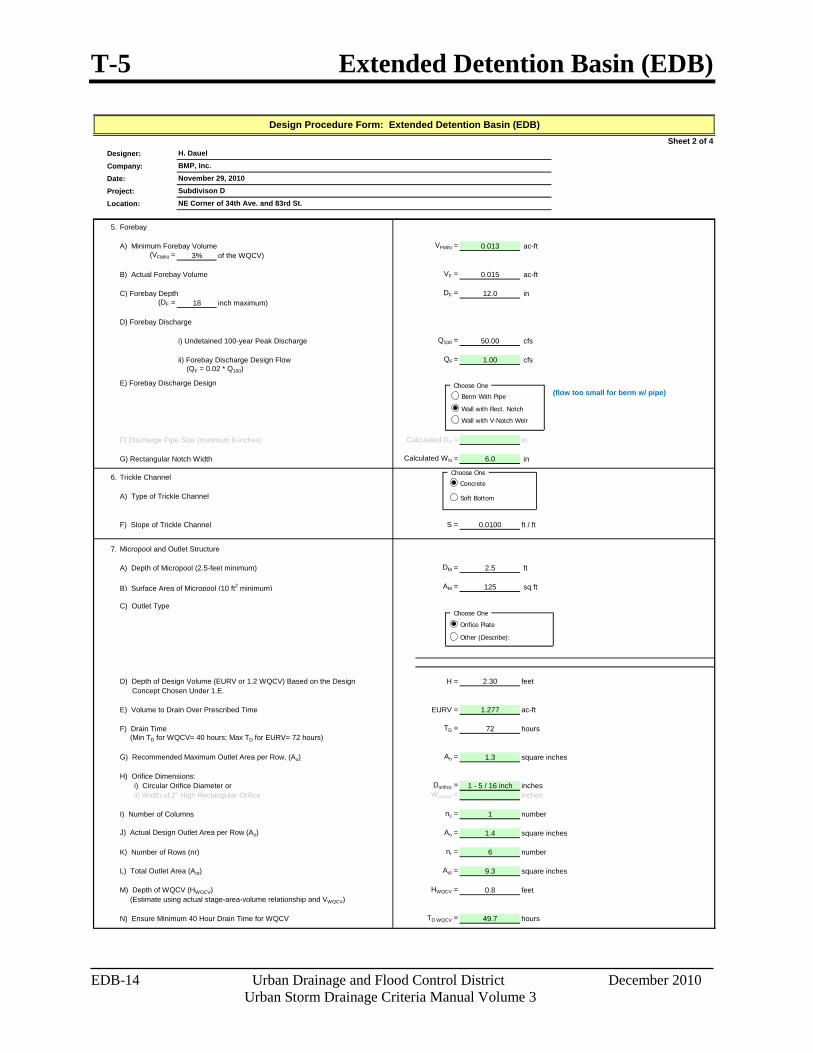
5. Forebay
A) Minimum Forebay Volume VFMIN = 0.013 ac-ft (VFMIN = 3% of the WQCV)
B) Actual Forebay Volume VF = 0.015 ac-ft
C) Forebay Depth DF = 12.0 in (DF = 18 inch maximum)
D) Forebay Discharge
i) Undetained 100-year Peak Discharge Q100 = 50.00 cfs
ii) Forebay Discharge Design Flow QF = 1.00 cfs (QF = 0.02 * Q100)
E) Forebay Discharge Design
F) Discharge Pipe Size (minimum 8-inches) Calculated DP = in
G) Rectangular Notch Width Calculated WN = 6.0 in
6. Trickle Channel
A) Type of Trickle Channel
F) Slope of Trickle Channel S = 0.0100 ft / ft
7. Micropool and Outlet Structure
A) Depth of Micropool (2.5-feet minimum) DM = 2.5 ft
B) Surface Area of Micropool (10 ft2 minimum) AM = 125 sq ft
C) Outlet Type
D) Depth of Design Volume (EURV or 1.2 WQCV) Based on the Design H = 2.30 feet Concept Chosen Under 1.E.
E) Volume to Drain Over Prescribed Time EURV = 1.277 ac-ft
F) Drain Time TD = 72 hours (Min TD for WQCV= 40 hours; Max TD for EURV= 72 hours)
G) Recommended Maximum Outlet Area per Row, (Ao) Ao = 1.3 square inches
H) Orifice Dimensions: i) Circular Orifice Diameter or Dorifice = 1 - 5 / 16 inch inches ii) Width of 2" High Rectangular Orifice Worifice = inches
I) Number of Columns nc = 1 number
J) Actual Design Outlet Area per Row (Ao) Ao = 1.4 square inches
K) Number of Rows (nr) nr = 6 number
L) Total Outlet Area (Aot) Aot = 9.3 square inches
M) Depth of WQCV (HWQCV) HWQCV = 0.8 feet (Estimate using actual stage-area-volume relationship and VWQCV)
N) Ensure Minimum 40 Hour Drain Time for WQCV TD WQCV = 49.7 hours
(flow too small for berm w/ pipe)
Subdivison DNovember 29, 2010BMP, Inc.
Design Procedure Form: Extended Detention Basin (EDB)
H. Dauel
NE Corner of 34th Ave. and 83rd St.
Choose One
Wall with Rect. Notch
Berm With Pipe
Choose One
Orifice Plate
Other (Describe):
Choose One
Concrete
Soft Bottom
Wall with V-Notch Weir
Extended Detention Basin (EDB) T-5
December 2010 Urban Drainage and Flood Control District EDB-15 Urban Storm Drainage Criteria Manual Volume 3
Sheet 3 of 4Designer:Company:Date:Project:Location:
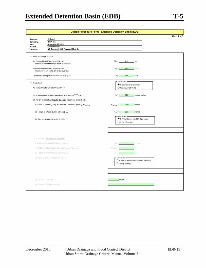
8. Initial Surcharge Volume
A) Depth of Initial Surcharge Volume DIS = 6.0 in (Minimum recommended depth is 4 inches)
B) Minimum Initial Surcharge Volume VIS = 55.5 cu ft (Minimum volume of 0.3% of the WQCV)
C) Initial Surcharge Provided Above Micropool Vs= 62.5 cu ft
9. Trash Rack
A) Type of Water Quality Orifice Used
B) Water Quality Screen Open Area: At = 38.5*(e-0.095D)*AotAt = 317 square inches
C) For 2", or Smaller, Circular Opening (See Fact Sheet T-12):
i) Width of Water Quality Screen and Concrete Opening (Wopening) Wopening = 12.0 inches
ii) Height of Water Quality Screen (HTR) HTR = 55.6 inches
iii) Type of Screen, Describe if "Other"
D) For 2" High Rectangular Opening:
i) Width of Rectangular Opening (Worifice) W = inches
ii) Width of Water Quality Screen Opening (Wopening) Wopening = ft
iii) Height of Water Quality Screen (HTR) HTR = ft
iv) Type of Screen, Describe if "Other"
v) Cross-bar Spacing inches
vi) Minimum Bearing Bar Size
BMP, Inc.H. Dauel
Design Procedure Form: Extended Detention Basin (EDB)
November 29, 2010Subdivison DNE Corner of 34th Ave. and 83rd St.
Choose One
Circular (up to 2" diameter)
Rectangular (2" high)
Choose OneS.S. Well Screen with 60% Open Area*
Other (Describe):
Choose One
Aluminum Amico-Klemp SR Series (or equal)
Other (Describe):
T-5 Extended Detention Basin (EDB)
EDB-16 Urban Drainage and Flood Control District December 2010 Urban Storm Drainage Criteria Manual Volume 3
Sheet 4 of 4Designer:
Company:
Date:
Project:
Location:
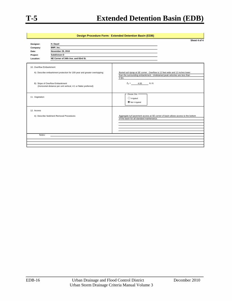
10. Overflow Embankment
A) Describe embankment protection for 100-year and greater overtopping:
B) Slope of Overflow Embankment ZE = 4.00 ft / ft (Horizontal distance per unit vertical, 4:1 or flatter preferred)
11. Vegetation
12. Access
A) Describe Sediment Removal Procedures
Notes:
Design Procedure Form: Extended Detention Basin (EDB)
November 29, 2010
BMP, Inc.
H. Dauel
Subdivison D
of the basin for all standard maintenance.
NE Corner of 34th Ave. and 83rd St.
Buried soil riprap at SE corner. Overflow is 12 feet wide and 12 inches lower than the surrounding embankment. Undetained peak velociies are less than 5 fps.
Aggregate turf pavement access at SE corner of basin allows access to the bottom
Choose One
Irrigated
Not Irrigated