extended ransac algorithm for automatic detection
TRANSCRIPT

HAL Id: halshs-00278397https://halshs.archives-ouvertes.fr/halshs-00278397v2
Submitted on 16 Jun 2008
HAL is a multi-disciplinary open accessarchive for the deposit and dissemination of sci-entific research documents, whether they are pub-lished or not. The documents may come fromteaching and research institutions in France orabroad, or from public or private research centers.
L’archive ouverte pluridisciplinaire HAL, estdestinée au dépôt et à la diffusion de documentsscientifiques de niveau recherche, publiés ou non,émanant des établissements d’enseignement et derecherche français ou étrangers, des laboratoirespublics ou privés.
EXTENDED RANSAC ALGORITHM FORAUTOMATIC DETECTION OF BUILDING ROOF
PLANES FROM LIDAR DATAFayez Tarsha-Kurdi, Tania Landes, Pierre Grussenmeyer
To cite this version:Fayez Tarsha-Kurdi, Tania Landes, Pierre Grussenmeyer. EXTENDED RANSAC ALGORITHMFOR AUTOMATIC DETECTION OF BUILDING ROOF PLANES FROM LIDAR DATA. Thephotogrammetric journal of Finland, 2008, 21 (1), pp.97-109. <halshs-00278397v2>
TARSHA-KURDI, F., LANDES, T., GRUSSENMEYER, P., (2008). Extended RANSAC algorithm for automatic detection of building roof planes from Lidar data.
The Photogrammetric Journal of Finland. Vol. 21, n°1, 2008, pp.97-109.
EXTENDED RANSAC ALGORITHM FOR AUTOMATIC DETECTION OF BUILDING ROOF PLANES FROM LIDAR DATA
F. Tarsha-Kurdi*, T. Landes, P. Grussenmeyer
Photogrammetry and Geomatics Group MAP-PAGE UMR 694, Graduate School of Science and Technology (INSA), 24 Boulevard de la Victoire, 67084 STRASBOURG, France.
(fayez.tarshakurdi|tania.landes|[email protected]) ABSTRACT Airborne laser scanner technique is broadly the most appropriate way to acquire rapidly and with high density 3D data over a city. Once the 3D lidar data are available, the next task is the automatic data processing, with major aim to construct 3D building models. Among the numerous automatic reconstruction methods, the techniques allowing the detection of 3D building roof planes are of crucial importance. For this purpose, this paper studies the Random Sample Consensus (RANSAC) algorithm. Its principle and pseudocode - seldom detailed in the related literature - as well as its complete analyse are presented in this paper. Despite all advantages of this algorithm, it gives sometimes erroneous results. That can be explained by the fact that it uses a pure mathematical principle for detecting the roof planes. So it looks for the best plane without taking into account the particularity of the captured object. The extended RANSAC algorithm proposed in this paper allows harmonizing the mathematical aspect of the algorithm with the geometry of a roof. It is shown that the extended approach provides very satisfying results, even in the case of very weak point density and for different levels of building complexity. Moreover, the adjacency relationships of the neighbouring roof planes are described and analysed. Hence the roof planes are successfully detected and adjacency relationships of the adjacent roof planes are calculate. Finally the automatic building modelling can be carried out easily.
1. INTRODUCTION The quick acquisition of 3D data as well as the automatic data processing are two key-tasks for the majority of surveying fields. Airborne laser scanning systems generate 3D data with high speed, good accuracy and density. Thus, the use of this technique in urban region is more and more frequent. In order to construct automatically 3D city models, two successive steps have to be considered. The first one is the automatic segmentation of the point cloud into three classes which are terrain, vegetation and buildings. Once the city cloud is segmented, the modelling of buildings can be started. Two types of approach called model-driven and data-driven approaches in the literature are proposed for constructing building models. The model-driven approaches search the most appropriate model among primitive building models contained in a model library (Maas and Vosselman, 1999). They consider that a primitive building can be described by a set of parameters. That implies to calculate the values of the parameters before constructing the 3D model. On the other hand, data-driven approaches try to simulate each part of the building point cloud in order to obtain the nearest or the more faithful polyhedral model (Rottensteiner, 2003). In the context of data-driven approaches which provide more universal models, the automatic detection of planes is a crucial operation. Many methods are proposed in order to carry out this procedure such as region growing, 3D Hough-transform and RANSAC. Since region growing

TARSHA-KURDI, F., LANDES, T., GRUSSENMEYER, P., (2008). Extended RANSAC algorithm for automatic detection of building roof planes from Lidar data.
The Photogrammetric Journal of Finland. Vol. 21, n°1, 2008, pp.97-109.
algorithms are sometimes not very transparent and not homogenously applied, the two last techniques were studied and compared by (Tarsha-kurdi et al., 2007 b). This analytic study of both algorithms, in terms of processing time and sensitivity to cloud characteristics, shows that despite the limitation encountered in both methods, RANSAC algorithm is still more efficient than the first one. Under other advantages, its processing time is negligible even when the input data size is very large. On the other hand, Hough-transform is very sensitive to the segmentation parameter values. In this paper the RANSAC algorithm is extended to be able to solve the majority of building cases and to exceed its limitations. Furthermore, its principles and the pseudocodes are detailed. In order to clarify its operating mode and assessment, it has been applied on samples of buildings with different forms and complexity levels.
2. RANSAC ALGORITHM FOR PLANE DETECTION
2.1 Related works and principle In Image Processing, RANdom SAmple Consensus (RANSAC) algorithm is used to detect mathematical features like straight lines and circles. Its principle is well explained by (Fischler and Bolles, 1981; McGlone et al., 2004; Nguyen et al., 2005). In the field of automatic buildings modelling based on lidar data, many authors suggest its use for achieving different tasks. For example, (Ameri and Fritsch, 2000; Brenner, 2000) use RANSAC algorithm for detecting the building roof planes. (Forlani et al., 2006) apply RANSAC algorithm in order to correct the building roof segmentation result which are obtained using a partition in 8 classes of the gradient orientation. Moreover, to carry out the 2D segmentation of the building contour polygon pixels into straight lines, the same technique is also applied. (Bretar and Roux, 2005) use the Normal Driven RANSAC (ND-RANSAC) for extracting 3D planar primitives. For this purpose, they calculate the normal vectors for each point. Then, they select randomly three points but having the same orientation of normal vectors. In our case, RANSAC algorithm is used with the aim of roof planes detection. The principle of RANSAC algorithm consists to search the best plane among a 3D point cloud. In the same time, it reduces the number of iterations, even if the number of points is very large. For this purpose, it selects randomly three points and it calculates the parameters of the corresponding plane. Then it detects all points of the original cloud belonging to the calculated plane, according to a given threshold. Afterwards, it repeats these procedures N times; in each one, it compares the obtained result with the last saved one. If the new result is better, then it replaces the saved result by the new one.
2.2 RANSAC algorithm This algorithm needs four input data which are:
- The 3D point cloud (point_list) which is a matrix of three coordinate columns X, Y and Z.
- The tolerance threshold of distance t between the chosen plane and the other points. Its value is related to the altimetric accuracy of the point cloud.
- The forseeable_support is the maximum probable number of points belonging to the same plane. It is deduced from the point density and the maximum foreseeable roof plane surface.
- The probability α which is a minimum probability of finding at least one good set of observations in N trials. It lies usually between 0.90 and 0.99.

TARSHA-KURDI, F., LANDES, T., GRUSSENMEYER, P., (2008). Extended RANSAC algorithm for automatic detection of building roof planes from Lidar data.
The Photogrammetric Journal of Finland. Vol. 21, n°1, 2008, pp.97-109.
The following algorithm details the pseudocode of RANSAC algorithm for plane detection: 1. bestSupport = 0; bestPlane(3,1) = [0, 0, 0] 2. bestStd = ∞; i = 0 3. ε = 1 – forseeable_support/length(point_list) 4. N=round (log (1 – α)/log (1 – (1 – ε) ^3)) 5. while (i <= N) 6. j = pick 3 points randomly among (point_list) 7. pl = pts2plane(j) 8. dis = dist2plan(pl, point_list) 9. s = find(abs(dis)<= t) 10. st = Standard_deviation (s) 11. if (length(s) > bestSupport or (length(s) = bestSupport and st < bestStd)) then 12. bestSupport = length (s) 13. bestPlan = pl; bestStd = st; endif 14. i = i+1; endwhile In this pseudocode, ε is a percentage of observations allowed to be erroneous; the function pts2plane calculates the plane parameters from three chosen points. It is advised to use the normal form of the plane (Equation 1) instead of the classical form in order to consider the general expression of a plane:
cos θ. cos φ. X + sin θ. cos φ. Y + sin φ. Z = ρ (1) where θ, φ and ρ are the parameters of the normal passing through the origin, so they are constant. The function dist2plan calculates the signed distances between point set and given plane (the distance takes negative or positive value) as given in Equation 2:
ρϕϕθϕθ - ZYX cos cos)X,Y,Z( dist2plane .sin.cossin. ++= (2)
where X, Y and Z are the three columns of the matrix point_list; θ, φ and ρ are the plane parameters (see Equation 1). The number of trials N can be calculated using Equation 3 as it is presented in the pseudocode. (3) where s is the minimum number of points necessary to calculate the parameters of the model (in the case of a planar model, s=3). It is important to note that the number of trials N can be considered directly as an input of the algorithm, instead of calculating it by a pure probability law. For this purpose, a table of different urban typologies and point densities can suggest the N value. Therefore, it replaces the introduction of values for forseeable_support and α. This operation is one of the modifications proposed for improving the basic RANSAC algorithm. In order to detect the whole roof planes, the algorithm is applied several successive times. In each iteration, the set of considered points is excluded from the original cloud. This operation is repeated until the number of non-modelled points becomes smaller than a given threshold.
))1(1log()1log(
sNεα−−−
=

TARSHA-KURDI, F., LANDES, T., GRUSSENMEYER, P., (2008). Extended RANSAC algorithm for automatic detection of building roof planes from Lidar data.
The Photogrammetric Journal of Finland. Vol. 21, n°1, 2008, pp.97-109.
2.3 Quantitative analysis In order to assess the capacities of the algorithm, two samples of buildings are used. They contain buildings of different forms and complexity levels. Only some results are illustrated in this paper, but they are based on characteristic samples (covering simple as well as complex building types) and consider low and high point densities. The first sample contains 11 buildings and its point density is equal to 7 points/m². The second sample contains 62 buildings, with a point density of 1.3 points/m². Fig.1a and 1b present the results of roof planes detection using RANSAC algorithm.
Figure 1. Roof plane detection result using the RANSAC. The colours represent the different building roof planes a) Point density: 7 pts/m². b) Point density: 1.3 pts/m².
The application of classic RANSAC algorithm on these samples gives successful results in 70% of cases for different building forms and different point cloud densities. It means that it detects correctly the roof planes for 51 buildings. For example, Fig.1a illustrates very good plane detections, whereas Fig.-1b shows unsatisfying results. In extreme situations, the algorithm can provide unacceptable errors (Fig.5b). That can be explained by the use of a pure mathematical principle, without taking into account the particularity of the building lidar data. Moreover, it is important to note here that the plane definition used in this algorithm is completely different from that of the traditional geometry. On one hand, a plane in the traditional geometry is a surface containing the straight line in all directions. On the other hand, in the extended RANSAC algorithm, one plane is a thickness of points ranging between two parallel planes. That is why, it may detect a set of points which represents several roof planes or which belongs to several planes. Therefore, the classic algorithm needs to be adapted in order to detect the best roof planes instead of the best mathematical planes in a 3D point cloud. (McGlone et al., 2004) note that the RANSAC algorithm aims at significantly reducing the number of necessary trials for large N values. However, it reduces N at the expense of having no guarantee for a solution free of gross errors. That means that there is not any guarantee for obtaining the same result after each iteration. Afterwards, several experiments have been made on the point cloud including the 51 buildings, i.e. the cloud for which RANSAC generated successful results. They demonstrate that the iterative application of RANSAC algorithm gives the same set of roof planes, but in a different order. Since the plane order is not important here, the RANSAC algorithm can be considered as an algorithm which guarantees a successful result. Furthermore, the processing time, even in the case of a large point cloud, is negligible in comparison with the processing time required by other algorithms as 3D Hough-transform. For example, for the building illustrated on Fig. 1a, the needed processing time in the case of 3D Hough-transform is 230sec but only 15sec with the RANSAC algorithm. As evoked in previous sections, RANSAC algorithm provides not only results in a short time but also results of high quality with a large percentage of successful results. As explained in the next section, our approach consists in extending the RANSAC algorithm in order to detect automatically building roof planes using lidar data.
a) b)

TARSHA-KURDI, F., LANDES, T., GRUSSENMEYER, P., (2008). Extended RANSAC algorithm for automatic detection of building roof planes from Lidar data.
The Photogrammetric Journal of Finland. Vol. 21, n°1, 2008, pp.97-109.
3. EXTENSION OF RANSAC ALGORITHM Two directions are proposed for extending the capacities of RANSAC algorithm to a better roof plane detection. The first one is the improvement of the data quality; the second one is the adaptation of RANSAC algorithm to roof detection.
3.1 Improvement of data quality It is well known that the point cloud coordinates contain errors related to position accuracy, artefacts, and multipaths. Moreover, noise and the small details composing building roofs are considered as obstacles. At last, variable point densities may occur for the same building roof. So, irregular distribution of points on a building roof can also be a cause of errors in the calculated plane. All these reasons allow thinking about the necessity of improving the quality of the point cloud. This remark leads to generate a new point cloud. On the one hand, the new cloud should present a homogeneous point density, and on the other hand, the errors of point coordinates and the noise should be eliminated or decreased. For this purpose, a resampling of the building point cloud is performed firstly. The sampling value defining the generated DSM is deduced from the average point density (Tarsha-kurdi et al., 2007a); and then values are assigned to the DSM cells. In the latter operation, the original cloud is superimposed on the DSM grid. Hence, some cells are empty and other cells contain one or more points. In the case of a non empty cell, the corresponding DSM pixel takes the maximum of the Z values occurring among the points. In the case of an empty cell in the building body, the corresponding DSM pixel value takes the mean of the non null neighbouring pixels. On the one hand, this operation allows eliminating a high quantity of points describing the facades. On the other hand, it allows filling the empty pixels, while respecting the mathematical characteristic of the plane. Secondly, in order to decrease the errors of point coordinates and the noise, a simple low-pass filter is applied. The last step consists in converting the generated DSM into a 3D cloud. The analysis of the new point cloud shows that the position accuracy of the inner roof plane boundaries has decreased. This consideration is related to the low-pass filtering. Hence, the new cloud is used exclusively for detecting the roof planes, but not for the future building modelling operations where the return to the original point cloud is inevitable.
3.2 Adaptation of RANSAC algorithm
The second enhancement consists in adapting RANSAC algorithm, in order to adapt the mathematical aspect of the algorithm to the geometry of a roof. Indeed, RANSAC algorithm searches to detect the best mathematical plane in a building cloud, regardless if the detected plane represents a roof plane or another plane. The adaptation of RANSAC algorithm consists of improving its pseudocode and the quality of the detected planes. 3.2.1 Improvement of RANSAC algorithm: In section 2.2, the 11th line is the essential line in the algorithm, because it represents a gate which allows to accept or to refuse the calculated plane. Indeed, the used condition is the number of points belonging to the calculated plane. Then the

TARSHA-KURDI, F., LANDES, T., GRUSSENMEYER, P., (2008). Extended RANSAC algorithm for automatic detection of building roof planes from Lidar data.
The Photogrammetric Journal of Finland. Vol. 21, n°1, 2008, pp.97-109.
algorithm accepts the new plane if it contains more points than the last calculated one, else the new plane will be refused. After the experiments, it was found that the best condition for validating plane detection is to take into account not only the number of points, but also simultaneously the standard deviation. Indeed, the use of standard deviation decreases the negative influence of the distance tolerance threshold t. As already mentioned, this threshold allows accepting whole points having distances to the plane smaller than t. For example, let us take a “bad” plane which does not represent a roof plane, with a large standard deviation and containing a large number of points. In this case, in reason of the condition imposed by the number of points, the RANSAC algorithm will not accept another plane for replacing it. For solving this problem, a new threshold is introduced. This threshold is the number of points of the smallest foreseeable plane surface PN_S. It is equal to the product of the smallest foreseeable plane surface by the point density. Then the 11th line in the algorithm becomes:
if st < bestStd and length(s) > PN_S then (4)
After this modification, the percentage of successful results reached by the application of the adapted RANSAC algorithm reaches 85%. 3.2.2 Improvement of the detected planes quality: As already mentioned, the application of RANSAC algorithm allows the detection of planes which do not necessarily present roof planes. It represents perhaps one roof plane in addition to other noisy points which belong to other roof planes, as the points inside the red circles in Fig. 2a. These noisy points have to be eliminated from the detected plane, and have to be reassigned to the initial cloud. Furthermore, inside the detected plane, there are some lost points (inside the blue circle in Fig.2a). These points have to be added to the fitted plane and extracted from the cloud in the same time. The last two problems can be solved by applying mathematical morphology procedures on the binary Digital Surface Model (DSMb) calculated for the detected plane.
Figure 2. a) DSMb of the detected plane (yellow plane in Fig.2d); b) DSMb of the improved detected plane; b) DSMb of the remaining points after detecting the roof planes; d) Final result of roof planes detection.
Results obtained by processing the data of Fig.-2a are shown in Fig.-2b. If the detected plane represents a set of points belonging to different roof planes and distributed stochastically, then the plane is rejected. Moreover, an additional condition checking if the new parameters never occurred previously is added automatically to the 11th line of the algorithm. So this plane is avoided in the next trials.
a) b) c) d)

TARSHA-KURDI, F., LANDES, T., GRUSSENMEYER, P., (2008). Extended RANSAC algorithm for automatic detection of building roof planes from Lidar data.
The Photogrammetric Journal of Finland. Vol. 21, n°1, 2008, pp.97-109.
After detecting all planes covering perfectly the roof, the remaining points are normally either noisy points or small roof details (Fig.2c). For classifying these points, a region growing algorithm is used, deciding if the set of points represents noise or roof details. Hence, the two criteria used are the smallest foreseeable surface of a roof detail and the segment form. Thus, if the doubtful set of points represents noise, it is added to the nearest planes, else it is considered as a new plane. Fig.2d presents the final result of roof planes detection obtained with the extended RANSAC algorithm and validates the developed methodology.
4. CORRECTION OF THE DETECTED PLANES Before explaining the correction of the detected planes, it is important to know what kind of mutual relationships exist between adjacent planes. According to (Rottensteiner and Briese, 2003), there are two general types of mutual relationships: the intersection and the step edge (Fig.3a). In particular case, the last two kinds of mutual relationships can be found together. This case is called “intersection-step edge”.
Intersection Step edge
a) b)
Figure 3. a) General types of mutual relationships between
the adjacent roof planes b) Error made during
the automatic roof planes detection The extended RANSAC algorithm presented in the last paragraphs allows detecting automatically the building roof planes from the building point cloud. As explained in section 2.3, the plane definition used in this algorithm is completely different from that of the traditional geometry. The use of this plane definition generates an error (ε) if the detected plane intersects with one of its adjacent planes (Fig.3b). For example, in Fig. 3b there are two adjacent planes P1 and P2. The mutual relationship between them is the intersection. Supposing the plane P2 was detected before the plane P1, it will contain all points of the plane P2 with an additional set of points which represents the error (ε). In order to correct this error, firstly the point sets of the roof planes have to be detected from the original building point cloud. Then, the mean plane equations have to be calculated by using the theory of least squares. Secondly, the borders between the adjacent planes have to be detected from the building label image (Fig.4b). The next step consists in calculating the distances between each point of the detected borders and their adjacent planes. This procedure allows re-studying the distribution of the points of the borders between the adjacency planes. If one point is detected as misclassified, then the same procedure has to be applied on their adjacent points which do not belong to the detected borders, otherwise the other points of the detected planes borders are processed. Figs. 4a and 4c represent the results of the automatic detection of the roof planes before and after the correction.
P1 P2
ε
TARSHA-KURDI, F., LANDES, T., GRUSSENMEYER, P., (2008). Extended RANSAC algorithm for automatic detection of building roof planes from Lidar data.
The Photogrammetric Journal of Finland. Vol. 21, n°1, 2008, pp.97-109.
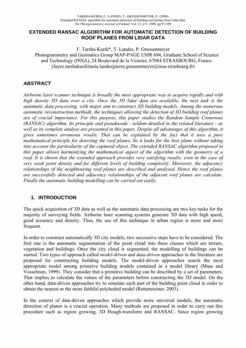
At this stage it is important to note that the corrected building label image does not represent exactly the reality but it represents an improvement of the detection plane result. The weak point in this improvement is the use of the mean plane equation because the traditional geometry plane definition is not the same as the used plane definition.
Figure 4. Correction of the detected roof planes (the colours represent the number of plane)
a) Building label image before the correction. b) Detected borders between the adjacent planes. c) Building label image after the correction.
Once the detected planes are corrected, it is necessary to analyse the result accuracy before studying the adjacency relationships between the adjacent roof planes.
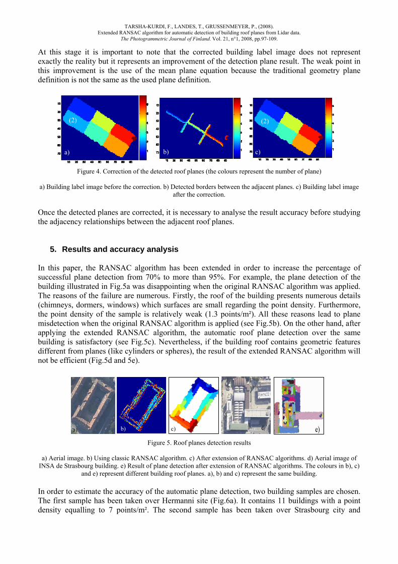
5. Results and accuracy analysis In this paper, the RANSAC algorithm has been extended in order to increase the percentage of successful plane detection from 70% to more than 95%. For example, the plane detection of the building illustrated in Fig.5a was disappointing when the original RANSAC algorithm was applied. The reasons of the failure are numerous. Firstly, the roof of the building presents numerous details (chimneys, dormers, windows) which surfaces are small regarding the point density. Furthermore, the point density of the sample is relatively weak (1.3 points/m²). All these reasons lead to plane misdetection when the original RANSAC algorithm is applied (see Fig.5b). On the other hand, after applying the extended RANSAC algorithm, the automatic roof plane detection over the same building is satisfactory (see Fig.5c). Nevertheless, if the building roof contains geometric features different from planes (like cylinders or spheres), the result of the extended RANSAC algorithm will not be efficient (Fig.5d and 5e).
Figure 5. Roof planes detection results
a) Aerial image. b) Using classic RANSAC algorithm. c) After extension of RANSAC algorithms. d) Aerial image of INSA de Strasbourg building. e) Result of plane detection after extension of RANSAC algorithms. The colours in b), c)
and e) represent different building roof planes. a), b) and c) represent the same building. In order to estimate the accuracy of the automatic plane detection, two building samples are chosen. The first sample has been taken over Hermanni site (Fig.6a). It contains 11 buildings with a point density equalling to 7 points/m². The second sample has been taken over Strasbourg city and
a) b) c)
(2) (2)
b) c) a)

TARSHA-KURDI, F., LANDES, T., GRUSSENMEYER, P., (2008). Extended RANSAC algorithm for automatic detection of building roof planes from Lidar data.
The Photogrammetric Journal of Finland. Vol. 21, n°1, 2008, pp.97-109.
contains 16 buildings representing different levels of architectural complexity (Fig.6d). Its point density is equal to 1.3 points/m².
Figure 6. Estimation of the accuracy of the automatic plane detection using the extended RANSAC algorithm
a) Aerial image of Hermanni site. b) Vectorisation of the building roofs from the aerial image. c) Mask of the segmented building roofs by using the extended RANSAC algorithm. d) Vectorisation of the building roofs by using the photogrammetric stereorestitution (reference mask). e) Vector mask of the same buildings created by vectorisation of the segmented building roofs detected by the extended RANSAC algorithm (model mask). The Fig. a), b) and c) use the sample of Hermanni site (point density: 7 points/m²). The Fig. d) and e) use the sample of Strasbourg city (point density: 1.3 points/m²) Before starting the analysis of the accuracy, it is important to recall that the extended RANSAC algorithm allows to detect two types of roof planes: the principal roof planes (see sections 3.2.1 and

TARSHA-KURDI, F., LANDES, T., GRUSSENMEYER, P., (2008). Extended RANSAC algorithm for automatic detection of building roof planes from Lidar data.
The Photogrammetric Journal of Finland. Vol. 21, n°1, 2008, pp.97-109.
3.2.2) and the roof detail planes (see section 3.2.3). The plane surface in the first type is greater than the smallest foreseeable plane surface PN_S (see paragraph 3.2.1) unlike the second type which is smaller than PN_S. The values of the algorithm parameters are defined as follows: t = 50 cm, N = 1500, α = 0,99, ε = 0,85 and PN_S = 50 m². 5.1 Results of roof plane detection Concerning the sample of the Hermanni site, only one aerial image is available for this site (Fig.6a). Thus, a not orthorectified vector image of the building roofs can be generated from this image (Fig.6b). This reference image allows only to compare the original number of principal planes with the number of detected planes. Table 1 shows that all principal roof planes are detected for 10 buildings in the Hermanni site. Globally, the results are very satisfying and confirm the potentiality of the extended RANSAC algorithm. Nevertheless, for the building number 8, two principal roof planes are detected instead of four planes. This means that two couples of planes have been merged. That can be explained by the fact that the mutual relationships between the planes of each couple are characterized by a step edge. Consequently, the value of the tolerance t is smaller than the height of the step between the two neighbouring planes. These good results must also be related to the high point density (7 points/m²) and to the large surfaces of the roof planes.
Table 1. Comparison of the number of original and detected roof planes of Hermanni site sample
Concerning the sample of Strasbourg city, a reference building roof model is created by photogrammetric stereorestitution. Its accuracy is about 20 cm in X and Y (Fig.6d). This vector image allows to compare the original number of principal and details planes with the number of detected roof planes (Table 2). Furthermore, it allows also to calculate many factors which describe the roof model accuracy in comparison with a reference model.
Table 2. Comparison of the number of original and detected roof planes of Strasbourg city sample Table 2 shows that the majority of principal roof planes are successfully detected except for some planes in the buildings number 11, 14, 15 and 16. In these buildings, several merged planes are met. Moreover, for each building, not all roof details are detected. Indeed, the detection of the roof detail is related to two factors: the surface of the detail and the mutual relationship of the detail plane with its neighbours. For example, if there are less than 9 points covering the detail plane, the detail plane will not be detected. Moreover, if the mutual relationship of the detail plane is the intersection and the detail slope is small, or if the mutual relationship is characterized by a step edge and the step height is smaller than the distance tolerance t, then the detail plane will not be detected.
Building number 1 2 3 4 5 6 7 8 9 10 11 Number of principal
roof planes 2 6 6 2 4 6 2 4 2 2 6
Number of principal detected roof planes 2 6 6 2 4 6 2 2 2 2 6
Building number 1 2 3 4 5 6 7 8 9 10 11 12 13 14 15 16 Number of principal
roof planes 1 2 2 2 2 5 2 2 4 5 3 7 12 2 14 20
Number of principal detected roof planes 1 2 2 2 5 5 2 2 4 5 2 7 12 2 12 18
Number of roof details 0 2 2 2 3 13 10 3 4 14 2 29 5 3 30 16 Number of detected
roof details 0 1 1 1 4 7 5 2 2 5 3 6 5 3 15 8
TARSHA-KURDI, F., LANDES, T., GRUSSENMEYER, P., (2008). Extended RANSAC algorithm for automatic detection of building roof planes from Lidar data.
The Photogrammetric Journal of Finland. Vol. 21, n°1, 2008, pp.97-109.
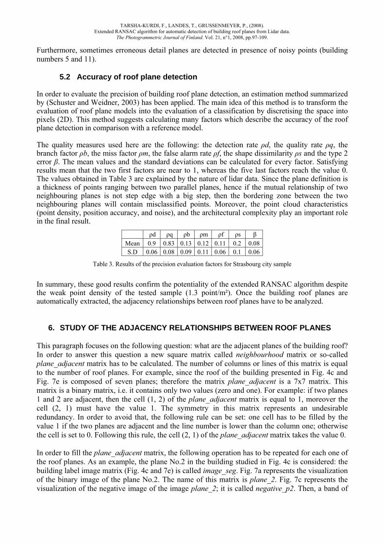
Furthermore, sometimes erroneous detail planes are detected in presence of noisy points (building numbers 5 and 11). 5.2 Accuracy of roof plane detection In order to evaluate the precision of building roof plane detection, an estimation method summarized by (Schuster and Weidner, 2003) has been applied. The main idea of this method is to transform the evaluation of roof plane models into the evaluation of a classification by discretising the space into pixels (2D). This method suggests calculating many factors which describe the accuracy of the roof plane detection in comparison with a reference model. The quality measures used here are the following: the detection rate ρd, the quality rate ρq, the branch factor ρb, the miss factor ρm, the false alarm rate ρf, the shape dissimilarity ρs and the type 2 error β. The mean values and the standard deviations can be calculated for every factor. Satisfying results mean that the two first factors are near to 1, whereas the five last factors reach the value 0. The values obtained in Table 3 are explained by the nature of lidar data. Since the plane definition is a thickness of points ranging between two parallel planes, hence if the mutual relationship of two neighbouring planes is not step edge with a big step, then the bordering zone between the two neighbouring planes will contain misclassified points. Moreover, the point cloud characteristics (point density, position accuracy, and noise), and the architectural complexity play an important role in the final result.
Table 3. Results of the precision evaluation factors for Strasbourg city sample In summary, these good results confirm the potentiality of the extended RANSAC algorithm despite the weak point density of the tested sample (1.3 point/m²). Once the building roof planes are automatically extracted, the adjacency relationships between roof planes have to be analyzed.
6. STUDY OF THE ADJACENCY RELATIONSHIPS BETWEEN ROOF PLANES This paragraph focuses on the following question: what are the adjacent planes of the building roof? In order to answer this question a new square matrix called neighbourhood matrix or so-called plane_adjacent matrix has to be calculated. The number of columns or lines of this matrix is equal to the number of roof planes. For example, since the roof of the building presented in Fig. 4c and Fig. 7e is composed of seven planes; therefore the matrix plane_adjacent is a 7x7 matrix. This matrix is a binary matrix, i.e. it contains only two values (zero and one). For example: if two planes 1 and 2 are adjacent, then the cell (1, 2) of the plane_adjacent matrix is equal to 1, moreover the cell (2, 1) must have the value 1. The symmetry in this matrix represents an undesirable redundancy. In order to avoid that, the following rule can be set: one cell has to be filled by the value 1 if the two planes are adjacent and the line number is lower than the column one; otherwise the cell is set to 0. Following this rule, the cell (2, 1) of the plane_adjacent matrix takes the value 0. In order to fill the plane_adjacent matrix, the following operation has to be repeated for each one of the roof planes. As an example, the plane No.2 in the building studied in Fig. 4c is considered: the building label image matrix (Fig. 4c and 7e) is called image_seg. Fig. 7a represents the visualization of the binary image of the plane No.2. The name of this matrix is plane_2. Fig. 7c represents the visualization of the negative image of the image plane_2; it is called negative_p2. Then, a band of
ρd ρq ρb ρm ρf ρs β Mean 0.9 0.83 0.13 0.12 0.11 0.2 0.08S.D 0.06 0.08 0.09 0.11 0.06 0.1 0.06

TARSHA-KURDI, F., LANDES, T., GRUSSENMEYER, P., (2008). Extended RANSAC algorithm for automatic detection of building roof planes from Lidar data.
The Photogrammetric Journal of Finland. Vol. 21, n°1, 2008, pp.97-109.
pixels around this plane has to be added to the matrix plane_2 defining a new matrix called plane2_extended (Fig.7b). At this stage, a new matrix called plane_2_adjacent is defined (Equation5 and Fig.7d). This matrix allows determining all adjacent planes of the plane No.2. Then it allows filling the part concerning the plane No.2 in the plane_adjacent matrix as shown in Fig. 7f.
plane_2_adjacent = plane2_extended * negative_p2 * image_seg (5)
where «*» is the element by element multiplication.
Figure 7. Calculation of the plane_adjacent matrix.
a) Visualization of the binary matrix plane_2. b) Visualization of the matrix plane2_extended. c) Visualization of the matrix negative_p2. d) Visualization of the matrix plane_2_adjacent.
e) Building label image. f) plane_adjacent matrix
7. CONCLUSION The RANSAC algorithm used for automatic roof planes detection from lidar data has been discussed in this paper. Its principle and its pseudocode have been detailed. The main advantage of RANSAC algorithm is the rapidity and the percentage of successful detected roof planes. To adapt its mathematical principle to the roof geometry, the algorithm has been extended. Thus, two enhancements were suggested in order to increase its capacities. The first one was the improvement of the original data by generating a new point cloud. The second improvement was the adaptation of the algorithm, so that it detects the best roof plane instead of the best mathematical one. Moreover, another improvement was suggested for looking up the quality of the detected roof planes. Afterward, the adjacency relationships between the neighbouring planes were studied using the neighbourhood matrix. Last of all, in order to evaluate the precision of building roof plane detection, two sets of buildings point clouds characterized by different densities and containing different building forms were used. Then a comparison of the number of original and detected roof planes was carried out. Furthermore, seven factors describing the accuracy of the roof plane detection in comparison with a reference model were calculated. Finally the satisfying results obtained for different clouds even with weak point density validate the proposed processing chain.
n° plane 1 2 3 4 5 6 7 1 0 1 1 1 0 0 0 2 0 0 1 0 0 0 0 3 0 0 0 1 1 0 0 4 0 0 0 0 1 1 0 5 0 0 0 0 0 1 0 6 0 0 0 0 0 0 1 7 0 0 0 0 0 0 0
a) b) c) d)
e)
f )

TARSHA-KURDI, F., LANDES, T., GRUSSENMEYER, P., (2008). Extended RANSAC algorithm for automatic detection of building roof planes from Lidar data.
The Photogrammetric Journal of Finland. Vol. 21, n°1, 2008, pp.97-109.
8. REFERENCES Ameri, B., Fritsch, D., 2000. Automatic 3D building reconstruction using plane-roof structures, Published by the ASPRS, Washington DC, accessed in the WWW (27/01/2004): www.ifp.uni stuttgart.de/publications/2000/pub2000.html
Brenner, C., 2000. Towards fully automatic generation of city models. International Archives of Photogrammetry and Remote Sensing, vol. 32, Part 3. Amsterdam, pp. 85-92.
Bretar, F., Roux, M., 2005. Hybrid image segmentation using lidar 3D planar primitives. ISPRS Proceedings. Workshop Laser scanning. Enschede, the Netherlands, September 12-14, 2005, pp 72-78.
Fischler, M. A., Bolles, R. C., 1981. Random Sample Consensus: a paradigm for model fitting with application to image analysis and automated cartography. Communications of the ACM, 24(6): 381-395.
Forlani, G., Nardinocchi, C., Scaioni, M., Zingaretti, P., 2006. Complete classification of raw lidar data and 3D reconstruction of buildings. Pattern Anal. Applic. 8: 357–374. DOI 10.1007/s10044-005-0018-2.
Maas, H-G., Vosselman, G., 1999. Two algorithms for extracting building models from raw laser altimetry data. ISPRS Journal of Photogrammetry & Remote Sensing Vol. 54, No. 2/3, pp. 153-163.
McGlone, J. C., M. Mikhail, E., Bethel, J., 2004. Manual of Photogrammetry. 5th ed, 1151 p. Published by the ASPRS, ISBN 1-57083-071-1
Nguyen, V., Martinelli, A., Tomatis, N., Siegwart, R., 2005. A comparison of line extraction algorithms using 2D laser rangefinder for indoor mobile robotics. IEEE/RSJ Proceedings. International conference on intelligent robots and systems, IROS, Edmonton, Canada, 6 p.
Rottensteiner, F., 2003. Automatic generation of high-quality building models from lidar data. IEEE Computer Graphics and Applications 23(6), pp. 42-51.
Rottensteiner, F., Briese, Ch., 2003. Automatic generation of building models from lidar data and the integration of aerial image. International Archives of Photogrammetry and Remote Sensing, Vol. XXXIV, Dresden, 2003, 7 p.
Schuster, H-F., Weidner, U., 2003. A new approach towards quantitative quality evaluation of 3D building models”. Workshop of the ISPRS. com IV, Challenges in Geospatial Analysis, Integration and Visualization II., Stuttgart, Germany, pp.156-163.
Tarsha-Kurdi, F., Landes, T., Grussenmeyer, P., 2007 a. Joint combination of point cloud and DSM for 3D building reconstruction using airborne laser scanner data. 2007 Urban Remote Sensing Joint Event, April 11-13th, Paris. ISPRS Workshop. 4th IEEE GRSS / WG III/2+5, VIII/1, VII/4 Joint Workshop on Remote Sensing & Data Fusion over Urban Areas and 6th Int. Symposium on Remote Sensing of Urban Areas. 1-4244-0712-5/07/$20.00 ©2007 IEEE, 7 p.
Tarsha-Kurdi, F., Landes, T., Grussenmeyer, P., 2007 b. Hough-transform and extended RANSAC algorithms for automatic detection of 3D building roof planes from lidar data. ISPRS Workshop on Laser Scanning 2007 and SilviLaser 2007, Espoo, Finland, Sept. 12-14th. ISPRS International Archives of Photogrammetry, Remote Sensing and Spatial Information Systems. Vol. XXXVI, Part 3 / W52, 2007, pp. 407-412.