extending a distributed cognition framework for … a distributed cognition framework for rapid...
TRANSCRIPT

- 1 -
Extending a distributed cognition framework for
rapid multi-site studies: an investigation of CCTV
systems in the school context
Ian Azille
Project report submitted in part fulfilment of the requirements for the degree of Master of Science (Human-Computer Interaction with Ergonomics) in the Faculty of Brain Sciences, University College London, 2012.
NOTE BY THE UNIVERSITY
This project report is submitted as an examination paper. No responsibility can be held by London University for the accuracy or completeness of the material therein.

- 2 -
ACKNOWLEDGMENTS
I would like to give a special thank you to my supervisor, Dr Dominic Furniss,
for his guidance, support and patience throughout the project. I am extremely
grateful to the staff of Redhand, Sunstone Systems and of the participating schools
for their time and cooperation and I would also like to thanks Professor Ann
Blandford for her contribution to the project.
Finally, I would like to extend my appreciation to my family, friends, peers and
colleagues for their intellectual, moral and financial support throughout my project.
It is through their combined support that I am able to complete my study.

- 3 -
ABSTRACT
The main aim of this project was to understand the situated use of CCTV
systems in schools from a distributed cognition perspective using Distributed
Cognition for Teamworking systems (DiCoT) as a framework for investigation. The
overall intended output from the project was to arrive at recommendations for
improvements towards efficiency, effectiveness and best practice. The secondary
aim was to assess the suitability of DiCoT for rapid multi-site studies. In addition to
DiCoT, the Distributed Information Resources Model was used to guide the data
gathering and the data analysis.
These frameworks had predominantly been used in the context of single site
studies with only one study being found to have used DiCoT to investigate multiple
sites (Werth, 2009). No prior studies were found that used either of the frameworks
in a rapid research or school CCTV context.
Data was gathered through a combination of preliminary system analysis (i.e. an
expert review) and an exploratory approach consisting of six iterative cycles of data
gathering, data analysis and supplier / developer debriefs over a two week period.
These cycles were arranged into two main phases to ensure there was sufficient time
for preliminary analysis and reflection between site visits.
The main finding was that the whole world environment approach of distributed
cognition is better suited than a traditional cognition perspective to the school
CCTV context to be able to understand not only the effectiveness of the CCTV
- 4 -
system as a technological artefact but to be able to identify whether the system is fit
for purpose by studying interactions between the social and technical system.
The existing DiCoT models assisted in providing a clear focus for the study
while in the field and at the analysis stage, which was critical under the time
constraints of a rapid study. The rapid scenario was of particular interest because of
the increasingly short product realization cycles within the product design /
development industry and its growing interest in more time efficient methods. The
study provided an opportunity to assess whether or not DiCoT was already a
sufficiently rapid technique or if there would be the need to extend the framework to
improve its use in this circumstance. The models also provided a foundation to be
able to compare data across sites to arrive at recommendations for improvements
towards efficiency, effectiveness and best practice. Concepts from personal and
rapid ethnography and additional tools were incorporated into the framework to
make both data gathering and analysis more efficient under the time constraints of
the project.
The study also partially explored the idea of a Conceptual Model as part of
DiCoT and the Resources Model with the aim of supporting an understanding of
breakdowns in interactions sequences and to help reasoning about appropriate next
steps to reduce gaps between the users’ model and the design model in distributed
cognition terms. However, it was not fully explored due to time constraints and
project scope.
- 5 -
TABLE OF CONTENTS
Acknowledgments…………………………………………………………….… 2
Abstract…………………………………………………………………….…… 3
Table of contents…….………………………………….……………….….…… 5
Table of figures……………………………….…………………………….…… 8
Table of tables…………………….….……………………………………..… 10
Chapter 1. Introduction .................................................................................. 11
Chapter 2. Background ................................................................................... 13
2.1. CCTV: systems, context and uses .................................................... 13
2.2. Studies on the use of CCTV systems ................................................ 14
2.2.1. Studies on the use of CCTV systems in schools .......................... 15
2.3. Field research: methodology background ......................................... 16
2.3.1. Ethnography .................................................................................. 16
2.3.2. Contextual inquiry ........................................................................ 17
2.4. Distributed cognition ........................................................................ 18
2.4.1. Fundamental principles of distributed cognition .......................... 18
2.4.2. DiCoT ........................................................................................... 19
2.4.3. Distributed Information Resources Model (Resources Model) .... 21
2.5. Application of distributed cognition to the CCTV system context .. 22
2.6. This study ......................................................................................... 23
Chapter 3. Method .......................................................................................... 24
3.1. Preliminary system evaluation .......................................................... 25
3.2. Pilot study ......................................................................................... 26
3.2.1. Pilot – part one .............................................................................. 26
3.2.2. Pilot – part two ............................................................................. 27

- 6 -
3.3. Data gathering ................................................................................... 29
3.3.1. Planned data gathering .................................................................. 30
3.3.1.1. Data gathering points ................................................................ 30
3.3.1.2. Observations ............................................................................. 32
3.3.1.3. Interviews ................................................................................. 33
3.3.1.4. Materials ................................................................................... 35
3.3.2. Adapted data gathering ................................................................. 35
3.4. Data Analysis .................................................................................... 36
3.5. Data Validation ................................................................................. 36
Chapter 4. Results .......................................................................................... 38
4.1. Overview .......................................................................................... 38
4.2. System Evolution Model .................................................................. 39
4.3. Social Structures Model .................................................................... 42
4.4. Information Flow Model .................................................................. 47
4.5. Physical Layout Model ..................................................................... 55
4.6. Artefact Model .................................................................................. 67
Chapter 5. Considering Design Alternatives .................................................. 82
Chapter 6. General Discussion ....................................................................... 85
6.1. Assessment of Distributed Cognition ............................................... 85
6.1.1. As a methodology for practitioners .............................................. 85
6.1.2. As a theory with the scope to extend DiCoT ................................ 87
6.2. Assessment of DiCoT ....................................................................... 89
6.2.1. Utility of existing models ............................................................. 89
6.2.2. As a methodology to support design ............................................ 90
6.2.3. As a methodology to support rapid multisite studies ................... 91

- 7 -
6.2.3.1. Templates and guides ............................................................... 92
6.2.3.2. Adapted personal ethnography ................................................. 92
6.2.3.3. Adapted rapid ethnography ...................................................... 92
Chapter 7. Conclusion .................................................................................... 94
Chapter 8. References .................................................................................... 95
Chapter 9. Appendix ...................................................................................... 97
8.1. Data gathering ................................................................................... 97
8.1.1. Participant Information Sheet ....................................................... 98
8.1.2. Participant Consent Form ............................................................. 99
8.2. Data analysis ................................................................................... 100
8.2.1. Processing the data ..................................................................... 100
8.2.2. Analysis using existing DiCoT models ...................................... 101
8.2.3. Considering a Conceptual Model ............................................... 102
8.2.3.1. Literature review ..................................................................... 102
8.2.3.2. Conceptual Model example .................................................... 103
8.3. Considering design alternatives ...................................................... 105
8.3.1. Wireframes ................................................................................. 105
- 8 -
TABLE OF FIGURES
Figure 1: Data gathering and analysis process overview ......................................... 25
Figure 2: Small site social and goal structures ......................................................... 44
Figure 3: Medium site social and goal structures ..................................................... 45
Figure 4: Large site social and goal structures ......................................................... 46
Figure 5: Input-output diagram ................................................................................. 48
Figure 6: Small site communication channels .......................................................... 48
Figure 7: Medium site communication channels ...................................................... 51
Figure 8: Large site communication channels .......................................................... 53
Figure 9: Small site layout model - room level ........................................................ 56
Figure 10: Medium site layout model - room level .................................................. 57
Figure 11: Small site layout model - desk level ....................................................... 59
Figure 12: Medium site layout model - desk level ................................................... 59
Figure 13: Viewer module main screen .................................................................... 62
Figure 14: Viewer module layout menu ................................................................... 63
Figure 15: Viewer module 'go from time' menu ....................................................... 64
Figure 16: Viewer module synch play mode ............................................................ 64
Figure 17: Viewer module 'select cameras' menu .................................................... 64
Figure 18: Manager module ..................................................................................... 65
Figure 19: Interaction sequence overview ................................................................ 71
Figure 20: Interaction sequence 1 ............................................................................. 72
Figure 21: Interaction sequence 1 - 'go from time' menu ......................................... 74
Figure 22: Interaction sequence 1 - 'synch play' mode ............................................. 75
Figure 23: Viewer module - main screen speed bar ................................................. 77
Figure 24: Interaction sequence variation 1.............................................................. 78
- 9 -
Figure 25: Interaction sequence variation 2.............................................................. 79
Figure 26: Interaction sequence variation 3.............................................................. 80
Figure 27: Data processing template example ........................................................ 101
Figure 28: Conceptual Model example 1 ............................................................... 104
Figure 29: Conceptual Model example 2 ............................................................... 105
Figure 30: Tabbed camera views concept .............................................................. 107
Figure 31: Tabbed camera views concept - dropdown menu ................................. 107
Figure 32: Integrated synch play concept ............................................................... 108
Figure 33: Alternative speed bar concept ............................................................... 109
Figure 34: Alternative header concept .................................................................... 110
Figure 35: Alternative header concept - copy to CD selected ................................ 110
Figure 36: Alternative header concept - start copying to CD selected .................. 111

- 10 -
TABLE OF TABLES
Table 1: Conceptual Model template ........................................................................ 29
Table 2: Data gathering points .................................................................................. 31
Table 3: Site visit schedule ....................................................................................... 32
Table 4: Interview checklist template ....................................................................... 34
Table 5: Operator walkthrough tasks ........................................................................ 36
Table 6: Small site actors and roles .......................................................................... 48
Table 7: Small site communication channels ........................................................... 49
Table 8: Medium site actors and roles ...................................................................... 51
Table 9: Medium site communication channels ....................................................... 51
Table 10: Large site actors and roles ........................................................................ 53
Table 11: Large site communication channels ......................................................... 53
Table 12: Design alternatives ................................................................................... 82
Table 13: Observation template example ................................................................. 97

- 11 -
CHAPTER 1. INTRODUCTION
The aims of the project can be divided into two main areas i.e. practical
contributions towards an improved understanding of the situated use of CCTV
systems in schools and theoretical contributions to Distributed Cognition for
Teamworking systems (DiCoT) (Furniss & Blandford, 2006). The study used two
distributed cognition frameworks i.e. DiCoT and the Distributed Information
Resources Model (the Resources Model) (Wright, Fields, & Harrison, 2000) to
gather data (through interviews and observation) and to carry out analysis.
These frameworks had predominantly been used in the context of single site
studies with only one study being found to have used DiCoT to investigate multiple
sites (Werth, 2009). No prior studies were found that used either of the frameworks
in a rapid research or school CCTV context.
The Background chapter describes CCTV systems and their evolving context of
use, followed by a literature review of studies into the use of CCTV systems. It then
gives an overview of field research methodology before describing distributed
cognition, its relevance to the school CCTV context and the two frameworks,
DiCoT and the Resources Model.
The Method chapter describes how the data gathering was planned, piloted and,
to a small extent, adapted as well as providing a brief introduction to the data
analysis. This chapter also provides a brief overview of two pilot studies that were
carried out and describes the idea of a Conceptual Model which was partially
explored as part of DiCoT and the Resources Model (with the aim of supporting an
- 12 -
understanding of breakdowns in interactions sequences and to help reasoning about
appropriate next steps to reduce gaps between the users’ model and the design
model in distributed cognition terms).
The Results chapter presents the findings of the study through the existing
DiCoT models namely, the System Evolution, Social Structures, the Information
Flow, the Physical Layout and the Artefact Models.
The Discussion chapter reviews how suitable distributed cognition in general
and the DiCoT framework in particular were for the context of this study from a
data gathering, data analysis and design perspective.

- 13 -
CHAPTER 2. BACKGROUND
This chapter gives general information on CCTV systems in schools, followed
by a literature review regarding studies into their use. It also provides a brief
overview of field research methodology and continues to describe the fundamental
principles of distributed cognition and the distributed cognition frameworks, DiCoT
and the Resources Model. It concludes by discussing the application of DiCoT to the
CCTV system context.
2.1. CCTV: systems, context and uses
CCTV is widely accepted to be ever-present in British city areas and is now also
an established part of UK educational institutions (Taylor, 2010). Although it is
difficult to determine the exact number of schools in the UK that have CCTV
systems, Taylor (2009) estimated that at least a fifth of all state schools in the UK
had CCTV in operation, whilst a prevalence as high as 85% was suggested by
survey findings from the Association of Teachers and Lecturers (ATL 2008).
Recent decades have seen CCTV technology develop from analogue to digital
and intelligent systems of the present day. As the technology continues to develop
so too does its ubiquity, its contexts of use and the diversity of its users (Keval,
2009). The system forming the focus of this study is a digital internet protocol based
system which captures images from motion-activated cameras.
CCTV users are no longer only trained ‘frequent use’ operators but now include
casual and infrequent users whose security tasks may form just a small subset of
- 14 -
their day-to-day activities. While a common goal of most CCTV systems has been
the prevention of crime and disorder through deterrence (Phillips, 1999; McCahill &
Finn, 2010; Taylor, 2011) – translating to security for pupils and staff and pupil
discipline in the school context – the social and technical changes have led to a
variety of products aimed at the needs and goals of a varied set of CCTV users
(Keval, 2009).
2.2. Studies on the use of CCTV systems
Keval (2009) argues that in order to understand how users interact with CCTV
systems, it is vital to observe them in context and talk to them to discover the key
problems associated with the technology they use to accomplish their tasks. She also
highlights that context research can be used to examine how well the overall
security system is operating in terms of its functional capabilities as well as to
identify whether the system is fit for purpose by studying interactions between the
social and technical system.
In her study, Keval (2009) investigates the use of CCTV systems in security
control room environments rather than in schools and discusses an earlier study by
Gill and Spriggs (2005) which also focused on the control room context. Both
studies conducted their research in a large number of CCTV control rooms. Keval
concluded that operators performed a ‘reactive task’ (i.e. time critical tasks)
involving locating scenes using CCTV cameras and other artefacts and argued that
the ability to perform these tasks effectively and efficiently depends on how well an
operator’s work-system is set-up and configured and the effectiveness of

- 15 -
communication (verbal and technical) between operators and other users. Other
CCTV control room studies conducted their research in 1-2 sites and, consequently,
failed to consider the effectiveness of task performance as a result of the efficiency
of the operators working environment and its impact on the security system. The
next section looks specifically at the studies done in the school context.
2.2.1. Studies on the use of CCTV systems in schools
Most studies done on the use of CCTV systems in schools have so far focused
on social impact (McCahill & Finn, 2010) and the regulatory system (Taylor, 2011).
As far as we are aware, no studies focusing on qualitatively understanding how
people use the systems in context. This study will use a similar contextual inquiry
approach as used by Keval (2009) in control room settings, except that the data
gathering and analysis will be guided by the principles of distributed cognition and,
more specifically, by DiCoT, explained in section 2.4.2. In addition to using a
context based approach, this study will also attempt to utilise rapid and multisite
assessment processes (explained in the next section) alongside the DiCoT and
Resources Model frameworks with the aim of making them more accessible to field
researchers (for example, by lowering cost for industry and supporting research and
analysis under tight time constraints).
- 16 -
2.3. Field research: methodology background
2.3.1. Ethnography
Ethnography is a form of social research which relies largely or partly on
‘participant observation’. It has a tendency to focus on one or few cases within a
single study and generally works with ‘unstructured data’ i.e. uncoded and
uncategorised data at the point of collection (Hammersley & Atkinson, 1995).
Ethnomethodology seeks to gather a detailed understanding of the ways in
which people work using an ethnographic approach (Button & Sharrock, 1995).
Both ethnography and ethnomethodology are well established in HCI as field
research techniques to elicit requirements for the design of new products and
systems across a wide range of work environments (Keval, 2009). However,
commonly cited practical limitations of these techniques include the length of time
needed for observation (typically six months or more) and as a result the financial
cost of research and the ease of access to work environments for prolonged periods.
These limitations led to the introduction of several alternative ethnographic
methods such as concurrent ethnography where ethnography is ongoing with system
design being carried out in parallel; autoethnography – a form of personal
ethnography where the researcher documents their own experiences while casting
themselves as the user – and ‘ethnographic-lite’ techniques such as ‘quick-and-dirty’
ethnography – sometimes carried out as a series of mini-studies – (Cunningham &
Jones, 2005) and ‘rapid’ ethnography.

- 17 -
Rapid ethnography, a form of ‘quick-and-dirty’ ethnography introduced by
Millen (2000) is a collection of field methods intended to provide a ‘reasonable’
understanding of users and their activities within a limited time in the field. Its key
elements include limiting or constraining the research focus and scope, using key
informants to narrow the focus of the field research appropriately before entering the
field (i.e. ‘zooming in on the important activities’) (Millen, 2000), capturing rich
field data by using multiple observers, interactive observation techniques and
collaborative qualitative data analysis.
‘Ethnographic lite’ techniques are often criticised for their potential to lose sight
of significant observations relevant to the study goal and to be arguably unsuitable
for some research projects where the work environment is large and complex.
However, triangulation of multiple techniques and further adaptation help to combat
their limitations. One such adaptation is contextual inquiry.
2.3.2. Contextual inquiry
Contextual inquiry was developed by Beyer and Holtzblatt (1998) as a set of
principles and practices that could be combined with other participatory techniques
to ‘codesign’ system and system work models with users. It consists of a set of
concepts to guide information collection and analysis rather than providing a set of
steps to follow.
With their first concept – context – Beyer and Holtzblatt (1998) state that
understanding users’ work is critical to system design and argue that the best way to
understand users’ work is to talk to them in their actual work environment. They
- 18 -
explain that the farther away users are from their work, the more abstract their
description of that work becomes. However, speaking to users ‘in context’ helps
them to articulate their work experiences and provides a clearer and more accurate
understanding of their day-to-day workflow.
In the second concept – partnership – they highlight that it is important to
develop dialogue with users in addition to observations to ensure an accurate picture
of the users’ tasks is obtained. The final concept – focus – suggests that the
researcher should fix their focus of inquiry on the user to maximise the chances of
obtaining relevant, important and useful information.
They describe contextual inquiry as a participatory technique that provides a
way to work for short periods of time with users at multiple geographically
dispersed sites. DiCoT, which will be discussed in section 2.4.2, draws on the
concepts of contextual inquiry
2.4. Distributed cognition
2.4.1. Fundamental principles of distributed cognition
Distributed cognition is an approach to understanding cognitive systems that is
concerned with whole world environments rather than only considering the
individual’s cognition (Hutchins, 1995a;).
The distributed cognition perspective on cognition can be identified by two
theoretical principles (Hollan, Hutchins, & Kirsh, 2000). These are that:

- 19 -
1. A cognitive process is bounded by the functional relationships of
contributing elements as opposed to by their physical / spatial
arrangement.
2. Distributed cognition is interested in the variety of means that may be
used in cognitive processes rather than taking the view that cognitive
events are confined only to the head of an individual.
Cognitive processes can be distributed in three ways i.e. across the members of a
social group, among internal and external (material or environmental) structure, and
through time such that the results of earlier events transform later events.
Distributed cognition extends the conventional view of cognition using a similar
foundation and theoretical framework for describing human activity in these larger
units of study (Carroll, 2003). It differs from conventional perspectives on cognitive
in its theoretical view that cognition is not just in the head, but in the world
(Norman, 1993) and in the methods that it applies in order to examine cognition “in
the wild” (Carroll, 2003). Furniss and Blandford (2006) developed DiCoT, a
codified method for applying distributed cognition which I will discuss next.
2.4.2. DiCoT
DiCoT is a framework for applying distributed cognition principles to teamwork
settings. It draws on the concepts of Contextual Inquiry (Beyer & Holtzblatt, 1998),
and uses five models to guide data gathering, analysis and to bridge the gap between
analysis and design (Furniss & Blandford, 2006).
- 20 -
The Information Flow Model is concerned with how information is processed as
well as by whom and by what from one stage to another. The Physical Model
analyses how layout supports communication among actors and access to artefacts.
The Artefact Model considers how artefacts, representations, and tools are designed
to support work and cognition. The Social Model aims to understand how the social
structures of the organisation relate to the goal structures of the system, how
cognition is socially distributed, and how the system learns through the developing
knowledge of the actors. The System Evolution Model aims to understand how the
cognitive system has evolved over time and it detects why things are done in certain
ways. Each model incorporates two to seven of 22 principles. These principles
enable the research subject to be looked at from different angles and with sufficient
depth. Reference will be made to the principles and how they relate to each model
throughout the Results chapter. They will be highlighted in bold italics to ensure
they can be easily identified.
Most of the previous studies that have used the DiCoT framework have done so
in the context of single site investigations. For example, Furniss and Blandford
(2006) developed and first applied DiCoT to the investigation of the London
Ambulance Service (LAS) control room; Webb (2004) applied and extended the
framework in his investigation of line control at the London Underground Victoria
Line control room; and Rajkomar (2010) (Rajkomar & Blandford, 2012) applied and
further extended DiCoT in an investigation into the use of Infusion Pumps in the
Intensive Care Unit. However, Werth (2010) (Werth & Furniss, 2012) applied
DiCoT to a multisite investigation into the use of medical equipment libraries.

- 21 -
Werth’s study discusses the challenge that was faced in finding similarities and
differences in working practices and the challenge of arriving at a general
understanding of equipment libraries but; Werth does also highlight that through
having many data points to analyse it was possible to identify best practice examples
and issues of concern which supported reasoning about the re-design of equipment
libraries. This study will attempt to extend thinking about how best DiCoT can be
used in multisite investigations.
2.4.3. Distributed Information Resources Model (Resources Model)
The Resources Model (Wright, Fields, & Harrison, 2000) is an approach to
analysis from a distributed cognition perspective that looks at how abstract
information structures can be distributed between people and technological artefacts
and used as resources for action. The Resources Model also describes how different
interaction strategies utilize different information structures as resources for action.
Abstract information structures can be plans, goals, system states, possibilities,
histories, or action-effect relations (described later in section 4.6) and interaction
strategies can be plan following, plan construction, goal matching, and history-based
selection and elimination (also described later in section 4.6).
The Resources Model will be used in this study to analyse the task of reviewing
and recording CCTV footage.

- 22 -
2.5. Application of distributed cognition to the CCTV system context
Few studies so far have taken a distributed cognition approach to investigating
the use of security and surveillance CCTV. As discussed, a study by Keval (2009)
uses an ethnographic approach to assess how well CCTV actually works for the
purposes for which it is deployed in a control room context.
Keval (2009) argues that a contextual inquiry and whole world environment
approach is needed in order to examine how well the overall security system is
operating in terms of its functional capabilities and whether or not the system is fit
for its intended purpose. The study focuses on the difficulties operators face with
control and co-ordination of surveillance tasks. Keval considers how communication
and collaboration between operators and external agencies and information
management impact on task performance and effectiveness in order to arrive at best
practice recommendations for CCTV managers, operators and designers.
The field study followed a sociotechnical approach and consisted of carrying out
naturalistic observations and interviews with operators at 14 CCTV control rooms.
As well as following a task-based contextual inquiry, a structured observation
checklist was used to collect observations and a structured interview checklist was
also used to identify CCTV managers’ security goals, stakeholders’ roles, operators’
tasks, artefacts used, and performance issues (an approach that had not been
previously applied in CCTV field research).
Keval’s findings revealed issues related to several artefacts (i.e. other than the
CCTV system) on the operators’ performance for example, operators were

- 23 -
overloaded with audio information from radios, telephones, and other systems. It
also revealed a wide range of communication failures such as the use of faulty radio
tools, background noise, poor placement of radio tools, excessive radio contact, etc.
Although Keval’s study focuses on the use of CCTV systems in control room
environments specifically, the study does suggest that distributed cognition is
suitable for CCTV analysis; however, this has not yet been fully explored.
The study also discusses the increasing diversity of CCTV users and highlights
that with the developments in technology, a growing number of these operators are
often novices. As a result, a detailed analysis of the CCTV system is needed to
support an understanding of how best to reduce task difficulty. Scaife and Rogers
(1996) argue that for modelling human computer interaction, the theory of
distributed cognition has clear benefits and Wright et al (2000) suggest that ‘it
[distributed cognition] might be used to understand how properties of objects on the
screen can serve as external representations and reduce cognitive effort’.
2.6. This study
I found no reported studies that focused on the use of CCTV in schools from a
distributed cognition perspective. This exploratory study will analyse the use of
CCTV in schools using the distributed cognition frameworks, DiCoT and Resources
Model. The study will take an ethnographic approach to data gathering and analysis
using audio recording, interviews and observation.

- 24 -
CHAPTER 3. METHOD
The method used for this study was a combination of preliminary system
analysis (i.e. an expert review) away from the context and situated research and
analysis. The situated part of the study took an exploratory approach consisting of 6
iterative cycles of data gathering, data analysis and supplier / developer debriefs.
These cycles were arranged into two main phases to ensure there was sufficient time
for preliminary analysis and reflection between site visits. Data on the situated use
of CCTV was collected through interviews and observational field studies in six
primary and secondary schools. An initial data gathering strategy was planned and
subsequently adapted following both the preliminary system analysis and
throughout the course of the study. The system was preliminarily analysed using the
Resources Model and the field data was analysed by using both DiCoT and the
Resources Model. The outcomes of these analyses guided further data gathering
efforts, with the objective of consolidating and comparing the representations
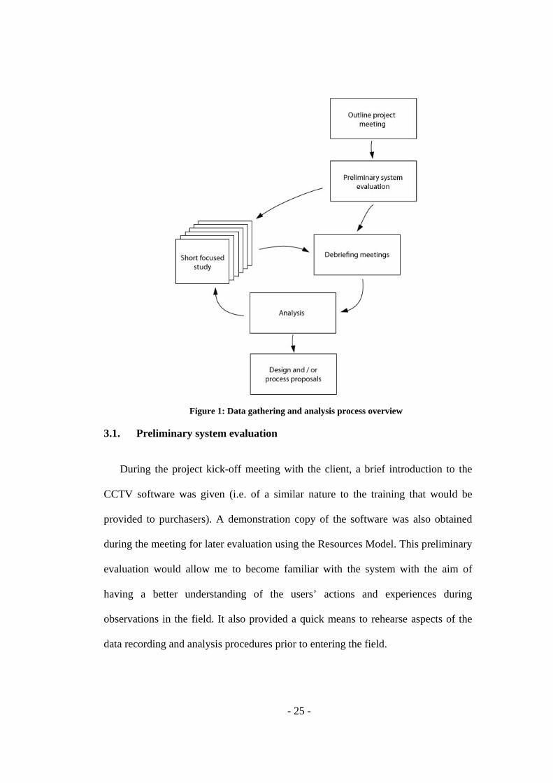
created. Figure 1 below provides an overview of the process that was adopted for
the study.
- 25 -
Figure 1: Data gathering and analysis process overview
3.1. Preliminary system evaluation
During the project kick-off meeting with the client, a brief introduction to the
CCTV software was given (i.e. of a similar nature to the training that would be
provided to purchasers). A demonstration copy of the software was also obtained
during the meeting for later evaluation using the Resources Model. This preliminary
evaluation would allow me to become familiar with the system with the aim of
having a better understanding of the users’ actions and experiences during
observations in the field. It also provided a quick means to rehearse aspects of the
data recording and analysis procedures prior to entering the field.

- 26 -
3.2. Pilot study
A pilot study was run in two parts at the start of the project. The aim of part one
was to get a better understanding of the system before entering the field and to
support thinking about how the required research data would be elicited, analysed
and reported. The aim of part two was to begin to test ideas for a Conceptual Model
within the DiCoT framework which was motivated by findings from part one of the
pilot (i.e. observing misinterpretation by participants of how parts of the system
should / would function). I will continue to provide a brief explanation of both parts.
3.2.1. Pilot – part one
Part one of the pilot used the Resources Model to evaluate both a separate and
unrelated system (i.e. a live movie maker programme – video creating / editing
software that allows videos and photos to be turned into movies) and the CCTV
system. In my review of the movie maker programme, the procedure involved
spending roughly 20 to 30 minutes exploring the software before navigating through
for a second time whilst making bulleted notes regarding the abstract information
structures of the Resources Model at each step of the journey. I found this fairly
unstructured approach difficult both in terms of ensuring that the system was being
reviewed in sufficient depth (i.e. ensuring that I remembered to consider all relevant
elements of the Resources Model while casting myself as a potential user) and also
in terms of summarising my own notes. This led me to take a more structured
approach during the evaluation of the CCTV system using the steps referred to in
section 4.6.

- 27 -
Additional outputs of part one of the pilot were a better understanding of the
system, an awareness of possible areas to be sensitive to when carrying out
observations and interviews and initial ideas for recording data i.e. templates for
recording data and to assist analysis. Templates were iterated throughout the project
after being able to assess their practicality and usefulness in the field.
3.2.2. Pilot – part two
As discussed later in appendix 8.2.3, although previous studies on distributed
cognition have suggested that mental models are used as mediating artefacts to
support activity (Hutchins, 1995a, p.290; Furniss & Blandford, 2006), there has
been little discussion into how these models can be described in distributed
cognition terms (including within the DiCoT framework).
It was apparent from part one of the pilot that participants experienced particular
difficulty in understanding how two parts of the system worked, namely, the
available actions and action-effect within the speed bar as well as how to copy
footage to CD. Following part one of the pilot, I was keen to explore the idea of a
Conceptual Models as part of DiCoT and the Resources Model with the aim of
supporting an understanding of breakdowns in interactions sequences and to help
reasoning about appropriate next steps to reduce gaps between the user’s model and
the design model. The design model is the abstract model of the system to be built
which is ideally based on the user's task, requirements and capabilities (Norman,
1986). The user creates a mental model of the system – the user's model – based on

- 28 -
their interpretation of the system image (i.e. the visible part of the device being
used).
It was important to determine if this could be practically explored within the
scope of this study and with relevance to a multiple user / multiple site investigation.
A short review of previous studies into conceptual models was conducted before
commencing this part of the pilot (see appendix 8.2.3).
Part two of the pilot was carried out in the field with two participants at the end
of the planned interviews and observations on the first two site visits. Close
attention was paid to areas where the operators experienced difficulty in using the
system before proceeding with a final conceptual model based task. For this model,
in order to elicit the information needed, participants were asked to imagine the
interviewer as a new employee / assistant and were asked to provide a detailed
description / instructions on how to use the CCTV system. The participants were
asked to do so for all the main tasks that they carry out with the system. They were
asked to be as descriptive as possible and to use metaphors or analogies to support
their explanations wherever they felt it to be useful e.g. 'you can imagine this as...'
or 'I usually think of this as...'.
Participants were also asked to include steps that they would usually take within
a task even if it didn’t include the use of the CCTV system (e.g. taking notes,
making phone calls etc).
Table 1 below was then used to make a comparison between internal and
external resource representations relevant to the users’ concepts at points in the
- 29 -
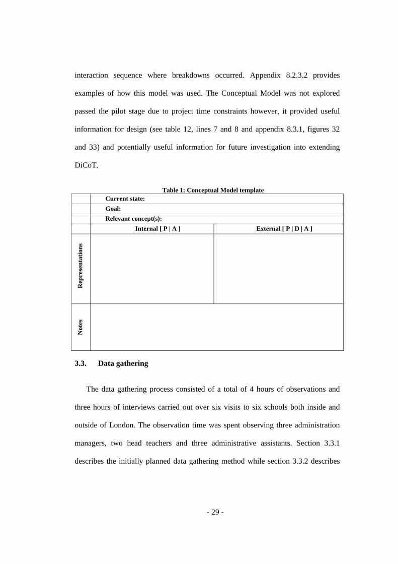
interaction sequence where breakdowns occurred. Appendix 8.2.3.2 provides
examples of how this model was used. The Conceptual Model was not explored
passed the pilot stage due to project time constraints however, it provided useful
information for design (see table 12, lines 7 and 8 and appendix 8.3.1, figures 32
and 33) and potentially useful information for future investigation into extending
DiCoT.
Table 1: Conceptual Model template Current state: Goal: Relevant concept(s): Internal [ P | A ] External [ P | D | A ]
Rep
rese
ntat
ions
Not
es
3.3. Data gathering
The data gathering process consisted of a total of 4 hours of observations and
three hours of interviews carried out over six visits to six schools both inside and
outside of London. The observation time was spent observing three administration
managers, two head teachers and three administrative assistants. Section 3.3.1
describes the initially planned data gathering method while section 3.3.2 describes
- 30 -
the adapted data gathering method. I had to apply for ethical clearance before I
could begin the data gathering process.
3.3.1. Planned data gathering
Data gathering consisted of an introductory interview followed by observation
and a brief closing interview to answer any questions raised during observation or to
gather non-observable data. A list of data gathering points, an interview guide and
an observation template were prepared to guide and support interviews, observations
and later analysis.
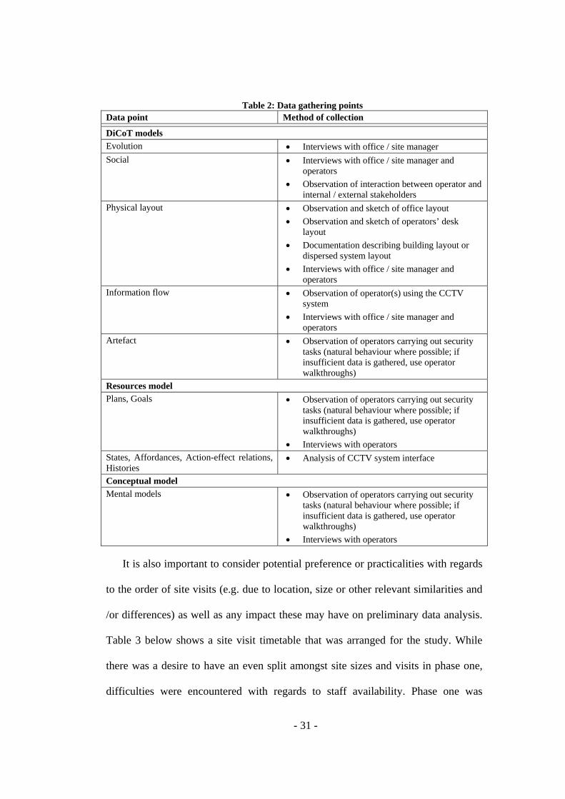
3.3.1.1. Data gathering points
When conducting observations in multiple sites and within a limited timescale, a
researcher needs to be well prepared in terms of what data to collect as it is
impossible to collect everything. Table 'x' below shows the data gathering points
that were established for this study.
- 31 -
Table 2: Data gathering points Data point Method of collection
DiCoT models Evolution • Interviews with office / site manager Social • Interviews with office / site manager and
operators • Observation of interaction between operator and
internal / external stakeholders Physical layout • Observation and sketch of office layout
• Observation and sketch of operators’ desk layout
• Documentation describing building layout or dispersed system layout
• Interviews with office / site manager and operators
Information flow • Observation of operator(s) using the CCTV system
• Interviews with office / site manager and operators
Artefact • Observation of operators carrying out security tasks (natural behaviour where possible; if insufficient data is gathered, use operator walkthroughs)
Resources model Plans, Goals • Observation of operators carrying out security
tasks (natural behaviour where possible; if insufficient data is gathered, use operator walkthroughs)
• Interviews with operators States, Affordances, Action-effect relations, Histories
• Analysis of CCTV system interface
Conceptual model Mental models • Observation of operators carrying out security
tasks (natural behaviour where possible; if insufficient data is gathered, use operator walkthroughs)
• Interviews with operators
It is also important to consider potential preference or practicalities with regards
to the order of site visits (e.g. due to location, size or other relevant similarities and
/or differences) as well as any impact these may have on preliminary data analysis.
Table 3 below shows a site visit timetable that was arranged for the study. While
there was a desire to have an even split amongst site sizes and visits in phase one,
difficulties were encountered with regards to staff availability. Phase one was

- 32 -
treated as a more in-depth data collection phase while phase two was helpful to
consolidate and compare the models throughout the study.
Table 3: Site visit schedule Small sites
(10 or less cameras) Medium sites (11 to 30 cameras)
Large sites (30 or more cameras)
Phase 1 - Site one - - Site two -
Phase 2 Site three Site four - - Site five Site six
3.3.1.2. Observations
Appointments would be made at each site with administration managers to
observe their (and other available operators) use of the CCTV system in context.
During the observations, attention would be paid to table 2 regarding data gathering
points and the data recording template (see appendix 8.1) would also serve as a
reminder of relevant DiCoT principles to be sensitive to. Video recording would not
be appropriate due to privacy reasons so data would be recorded through note taking
and audio recording of interviews. As observable incidents would potentially be
infrequent (and as a result, difficult to observe) it would be important to be prepared
to ask participants to walk through how the more commonly performed tasks are
carried out while again paying attention to the planned data gathering points and
DiCoT principles.
The first visits would serve as a pilot to assess the suitability of the planned data
gathering strategy however; data would be gathered with as much depth as possible.
Subsequent focused data gathering will aim to consolidate DiCoT models created
- 33 -
from preliminary analysis. Informal semi-structured interviews will also be used to
support data gathering.
3.3.1.3. Interviews
Semi-structured interviews would be used to gather unobservable data (e.g.
cognitive and domain related) and to answer questions that arise during observation.
Each visit would begin with a brief interview loosely following the structure
outlined in table 4. This serves to ensure that the participants have been provided
with the context and aims of the study and gives an opportunity to gain important
domain knowledge before observations begin. It also helps to build rapport and trust
early into the visit. Where possible, questions would be asked during observations.
However, where this is not practical, notes would be taken of questions to be asked
at an opportune moment. Visits would be concluded with a short debriefing
interview with the administrator / site manager to provide further clarification and /
or validation of findings during the visit.
Audio recording and note taking would be used to record data. While the audio
recording would be helpful to ensure all important interview data is gathered for
later analysis, note taking would provide a back up in the event of any later technical
problems with the recorded data. Note taking would also help to pace the interview.

- 34 -
Table 4: Interview checklist template Interview template
Questions Interview checklist Ev Evolution Pre-interview introduction
• Who is the interviewer? • What institution are they from? • Provide a background on the research topic. • Who do they want to interview and why? • What will the information be used for? • How long will the interview take?
Interview data gathering checklist • How will the personal and sensitive data be
protected? • Seek informed consent? • How will the data be analysed and used for future
work? • Seek permission for audio recording during the
interview? Interview checklist • Conduct the interviews in an environment in
which others will not be distracted. • If interviewees reveal out of the norm comments,
avoid giving any strong emotional responses, as this may influence the interviewee’s willingness to be open in later questions.
• Ask interviewees to respond in an honest and open manner and assure interviewees that their responses will be kept safe from other personnel.
• Inform interviewees that they can interrupt at any time to ask for clarification when unsure of any question.
Post-interview checklist • Summarise the interview theme and sum up main
issues. • Confirm the main findings with the
manager/operator to ensure the findings are accurate.
• Seek clarification of any comments made that may appear difficult to analyse later.
• Once the interview has been concluded, debrief the user about the study’s objectives in more detail than given in the introduction.
• Re-affirm that the information gathered from the interview will be kept anonymous and confidential.
19 When was CCTV first introduced into the site?
Why was it introduced? How has it and the site’s use of it evolved
over time? Are there any plans to change it or any
aspect of the current system in the future? Sc Social 21 What are your goals for CCTV at your
site? Who are the people involved in the site’s
security and use of the CCTV system? What are their roles, responsibilities, skills
and experience? How many operators work at the site in
one shift? 22 Is there a lot of overlap and sharing of
responsibilities? Ph/IF Physical Layout & Information Flow Can you describe the interactions between
operators and other CCTV stakeholders working in and outside the CCTV site?
CM Conceptual 20 Can you describe for me the overall
function and design of the CCTV system? So what would be your main requirements
for an imaginary new version of a system, were you about to acquire one?
Other What security tasks do operators perform? How frequently are these tasks carried out?
> daily, once daily, weekly, monthly, < monthly
What types of incidents are observed and how frequently do they occur?
How many cameras do operators use to monitor the surveillance areas?
What type of technology is used on the site to store and transmit CCTV video?
Can you describe in detail an error in the operation of the CCTV system which was made by yourself or another person who you were watching at the time?

- 35 -
3.3.1.4. Materials
The materials that were planned to be used were an interview checklist
containing questions and a guide to the general structure of the sessions, observation
sheets for taking notes of observations, a dictaphone for recording interviews, a
digital camera for taking still pictures of layouts and artefacts, participant
information sheets and consent forms. The participant information sheet and
participant consent form are in appendix sections 8.1.1 and 8.1.2, respectively.
3.3.2. Adapted data gathering
The data gathering strategy was defined and refined in the early stages of the
project (i.e. before entering the field) by considering the conclusions from the
preliminary system evaluation, pilot sessions and early discussions with the client.
Once in the field, data gathering was largely conducted as planned. However, minor
adjustments were made as a result of learning once data gathering had started. For
example, increased domain knowledge gained in the field highlighted the need for
more structured tasks due to the infrequency of incidents at sites visited.
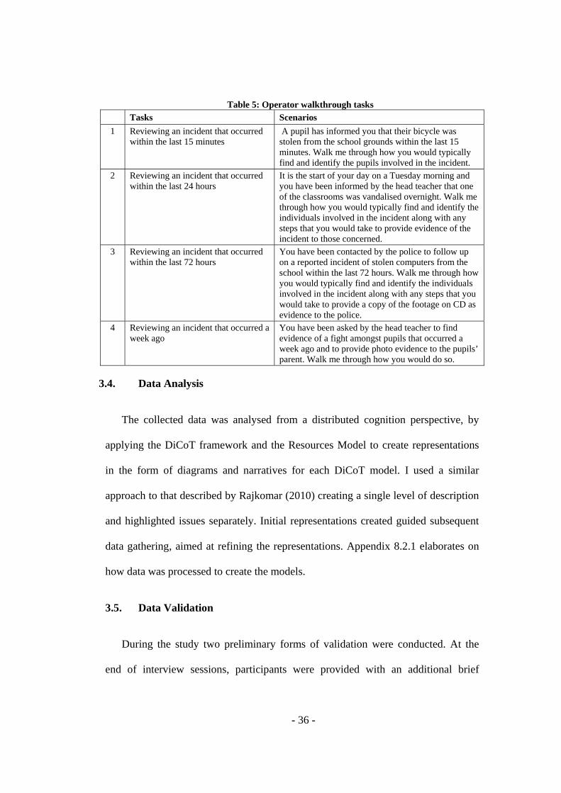
In addition to the data gathering previously mentioned, operators were asked to
walk / talk me through how the CCTV system would typically be used to carry out
the tasks in the table 5. These tasks were carried out towards the end of sessions and
operators were asked to think aloud as they walked through the system.
- 36 -
Table 5: Operator walkthrough tasks Tasks Scenarios 1 Reviewing an incident that occurred
within the last 15 minutes A pupil has informed you that their bicycle was stolen from the school grounds within the last 15 minutes. Walk me through how you would typically find and identify the pupils involved in the incident.
2 Reviewing an incident that occurred within the last 24 hours
It is the start of your day on a Tuesday morning and you have been informed by the head teacher that one of the classrooms was vandalised overnight. Walk me through how you would typically find and identify the individuals involved in the incident along with any steps that you would take to provide evidence of the incident to those concerned.
3 Reviewing an incident that occurred within the last 72 hours
You have been contacted by the police to follow up on a reported incident of stolen computers from the school within the last 72 hours. Walk me through how you would typically find and identify the individuals involved in the incident along with any steps that you would take to provide a copy of the footage on CD as evidence to the police.
4 Reviewing an incident that occurred a week ago
You have been asked by the head teacher to find evidence of a fight amongst pupils that occurred a week ago and to provide photo evidence to the pupils’ parent. Walk me through how you would do so.
3.4. Data Analysis
The collected data was analysed from a distributed cognition perspective, by
applying the DiCoT framework and the Resources Model to create representations
in the form of diagrams and narratives for each DiCoT model. I used a similar
approach to that described by Rajkomar (2010) creating a single level of description
and highlighted issues separately. Initial representations created guided subsequent
data gathering, aimed at refining the representations. Appendix 8.2.1 elaborates on
how data was processed to create the models.
3.5. Data Validation
During the study two preliminary forms of validation were conducted. At the
end of interview sessions, participants were provided with an additional brief

- 37 -
summary of the project’s aims and objectives and were given the opportunity to give
feedback on my initial understanding and interpretation of the data gathered during
the sessions. This served as an opportunity for participants to offer early
clarification on any possible areas of misinterpretation. After the first two site visits,
a debrief was also carried out with the client which was useful for refining the data
gathering. The future presentation of the results of the study to the client /
developers (which will happen after the submission of this thesis) will serve as final
data validation.

- 38 -
CHAPTER 4. RESULTS
4.1. Overview
This chapter summarises the results of the analysis conducted on the data
through the different models of the DiCoT framework. We first describe the System
Evolution Model examines how the cognitive system has evolved over time and it
detects why things are done in certain ways. Then the Social Model aims to
understand how the social structures of the organisation relate to the goal structures
of the system, how cognition is socially distributed, and how the system learns
through the developing knowledge of the actors.
The High-level Input-Output Model summarises the overall function of the
systems (i.e. in terms of teams and individuals involved in maintaining safety,
security and discipline within the school). Then the Information Flows Model
describes the information flows that exist in the activity of monitoring / reviewing
individuals and their activities using CCTV. The Physical Layout Model analyses
how the spatial arrangement of the work area and the CCTV system’s interface
supports communication among actors, access to artefacts and cognition. Finally,
the Artefact Model analyses how artefacts, representations, and tools are used to
store transform and communicate information and how they aid the coordination of
resources.

- 39 -
4.2. System Evolution Model
The System Evolution Model aims to understand how the cognitive system has
evolved over time and it detects why things are done in certain ways. I have scoped
the analysis around the legal and historical context of CCTV in schools. I will begin
with a very brief overview of the legal environment.
The use of CCTV in public and private spaces is legally impacted by the
principles within the Data Protection Act (DPA) 1998 which came into force in
2000 and is more directly referenced in the CCTV Code of Practice; a set of ‘good
practice’ recommendations published by the Information Commissioners Office
(ICO) in 2000 (and updated in 2008) aimed at outlining how the DPA would affect
the operation of CCTV systems. The act as it relates to CCTV covers issues such as
fair and lawful use (e.g. ensuring that individuals are aware that CCTV is in
operation on the school premises and that they are aware of its purpose), ensuring
that the broad purpose of use is provided to the ICO, ensuring its use is adequate and
not excessive (e.g. cameras shouldn’t be installed in areas where people have a
heightened expectation of privacy) and ensuring measures are taken to avoid
unauthorised or unlawful processing of personal data and against accidental loss or
destruction of, or damage to, personal data (Taylor, 2011). While these rules and
guidelines are not aimed solely or specifically at schools and although there is much
debate about how strictly UK schools adhere to their various legal obligations
regarding CCTV use, failure to comply would result in contravention of the law.
- 40 -
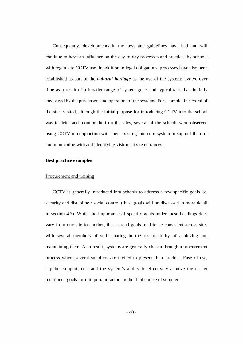
Consequently, developments in the laws and guidelines have had and will
continue to have an influence on the day-to-day processes and practices by schools
with regards to CCTV use. In addition to legal obligations, processes have also been
established as part of the cultural heritage as the use of the systems evolve over
time as a result of a broader range of system goals and typical task than initially
envisaged by the purchasers and operators of the systems. For example, in several of
the sites visited, although the initial purpose for introducing CCTV into the school
was to deter and monitor theft on the sites, several of the schools were observed
using CCTV in conjunction with their existing intercom system to support them in
communicating with and identifying visitors at site entrances.
Best practice examples
Procurement and training
CCTV is generally introduced into schools to address a few specific goals i.e.
security and discipline / social control (these goals will be discussed in more detail
in section 4.3). While the importance of specific goals under these headings does
vary from one site to another, these broad goals tend to be consistent across sites
with several members of staff sharing in the responsibility of achieving and
maintaining them. As a result, systems are generally chosen through a procurement
process where several suppliers are invited to present their product. Ease of use,
supplier support, cost and the system’s ability to effectively achieve the earlier
mentioned goals form important factors in the final choice of supplier.
- 41 -
Suppliers generally provide a brief initial training phase – to help initiate the
development of the staff’s expert coupling with the system – with further telephone
and online support also being available.
System visibility
Schools ensure that pupils, staff, parents and other visitors are made aware that
they are being monitored through a combination of informal verbal communication
and signage at site entrances and throughout the school.
Although cameras are often placed near areas where people have a heightened
expectation of privacy, such as changing rooms or toilet areas, none of the schools
visited went as far as to install cameras directly within these areas. Sites also
attempted to maintain a level of visibility of the cameras that would allow people to
know that CCTV was being used but that would minimise the chances of making
pupils feel ‘uncomfortable’ and ‘spied on’.
Issues of concern
Unauthorised access to personal data
Servers and power sources for the CCTV systems in schools are often not kept
in a sufficiently secure environment through a desire to make them accessible to the
many members of staff that share the responsibility of using it. However, this leaves
the system vulnerable to interference unauthorised individuals with a desire to
access personal data as well as providing an opportunity to turn the system off to
avoid being monitored by the cameras.
- 42 -
4.3. Social Structures Model
The Social Model aims to understand how the social structures of the
organisation relate to the goal structures of the system, how cognition is socially
distributed, and how the system learns through the developing knowledge of the
actors (Rajkomar, 2010).
Mapping between social structures and goal structures
Hutchins (1995a) and Furniss and Blandford (2006) describe how the social
structure of an organisation can be superimposed with a goal structure so that a
subordinate can only stop when their superior determines that their goals have been
met. Webb (2008) and Rajkomar (2010) also demonstrate how this model can be
diagrammatically illustrated. However, the representations used by Webb and
Rajkomar become overly complex in the context of schools and their use of CCTV
as the vast majority of goals and sub-goals are shared throughout the social
organisation.
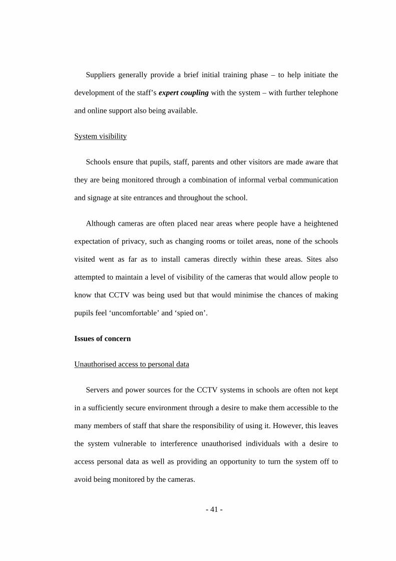
While figures 2, 3 and 4 do not aim to represent the social and goal structure of
all schools at the three site sizes mentioned (i.e. small, medium and large), they do
aim to give an overview of the main similarities and differences that were identified
during this study. These models are loosely based on the existing DiCoT adaptation
by Webb (2008). As mentioned, Webb’s approach was not fully appropriate for the
context being investigated here as roles were less well defined with multiple actors
within the same or similar roles (i.e. which would make the models overly complex
and arguably not very useful).

- 43 -
Some minor social and goal structure differences (dependent on the size of the
site) were identified. These are discussed next and summarised in figures mentioned
above
Small sites
In most of the schools visited, there was no direct mapping between the social
structure and the goal structure with regards to CCTV use. In the case of one small
site that was visited (as shown in figure 2), the goal of the head teacher (g1) is to
ensure maximum security and discipline on the site. Overseeing the activities of all
staff and providing support when necessary are amongst the important tasks of the
head teacher. The head teacher, the deputy head and general teaching staff share the
sub-goal of ensuring that any pupils caught on camera are identified (sg2.4). The
broader sub-goals of maximising the safety and security of the site and of the people
on it (sg1) and maintaining discipline / social control of pupils (sg2) are shared by
all actors (including secretaries). Further sub-goals are shared by all i.e. informing
and / or providing evidence to relevant team members (and to third parties when
necessary) of security / safety issues or criminal activity (sg1.2.1) and of pupil
misconduct (sg2.4.1).
A secretary on reception serves as the primary operator of the system with
support from a second secretary acting as a secondary operator during breaks / shift
handovers etc. They share the sub-goals of ensuring visitors are identified and that
only authorised visitors are allowed within the building (sg1.1), ensuring pupils
remain within the boundaries of the school (sg2.1) and monitoring and / or
- 44 -
reviewing pupil behaviour on site (sg2.3) along with the other sub-goals already
discussed.
A more informal relationship is kept with the school caretaker who provides
general support in operating the system.
Figure 2: Small site social and goal structures
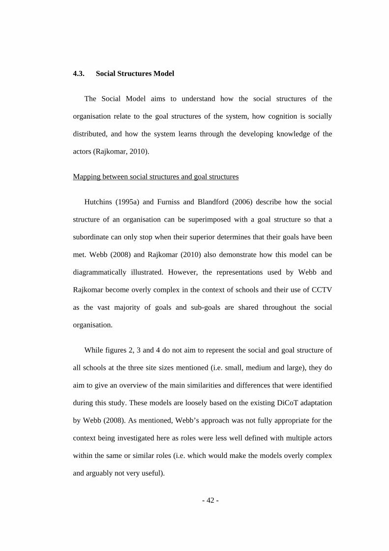
Medium sites
Variations in goal sharing were recognised across different site sizes. For
example, at one of the medium sized sites visited, the head teacher serves as one of
the primary operators with the sub-goal of maintaining discipline / social control of
pupils (sg2) while the secretary / receptionist has the sub-goal of maximising the
safety and security of the site and of the people on it (sg1) by monitoring visitors,
activity in and around the school and keeping staff and third parties informed of any
issues. The head teacher’s responsibilities are shared by the deputy head who serves
as a secondary operator. The head teacher oversees all activities and shares the
- 45 -
responsibility of identifying pupils caught on camera with the deputy head and
general teaching staff. The secretary’s responsibilities are shared with a second
secretary and informal operator support is provided to all by the IT department. All
of the operators share the responsibility of monitoring and / or reviewing criminal
activity (sg1.2) and informing and / or providing evidence to relevant team members
(and to third parties when necessary) of security / safety issues or criminal activity
(sg1.2.1)
Figure 3: Medium site social and goal structures
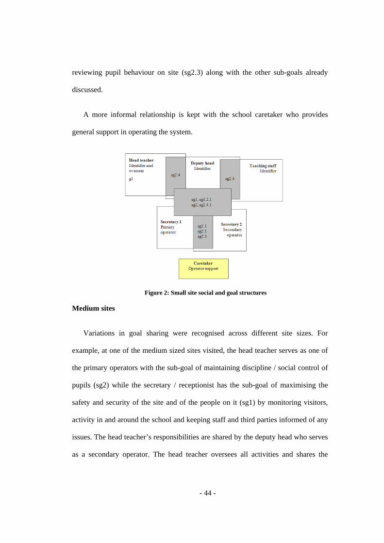
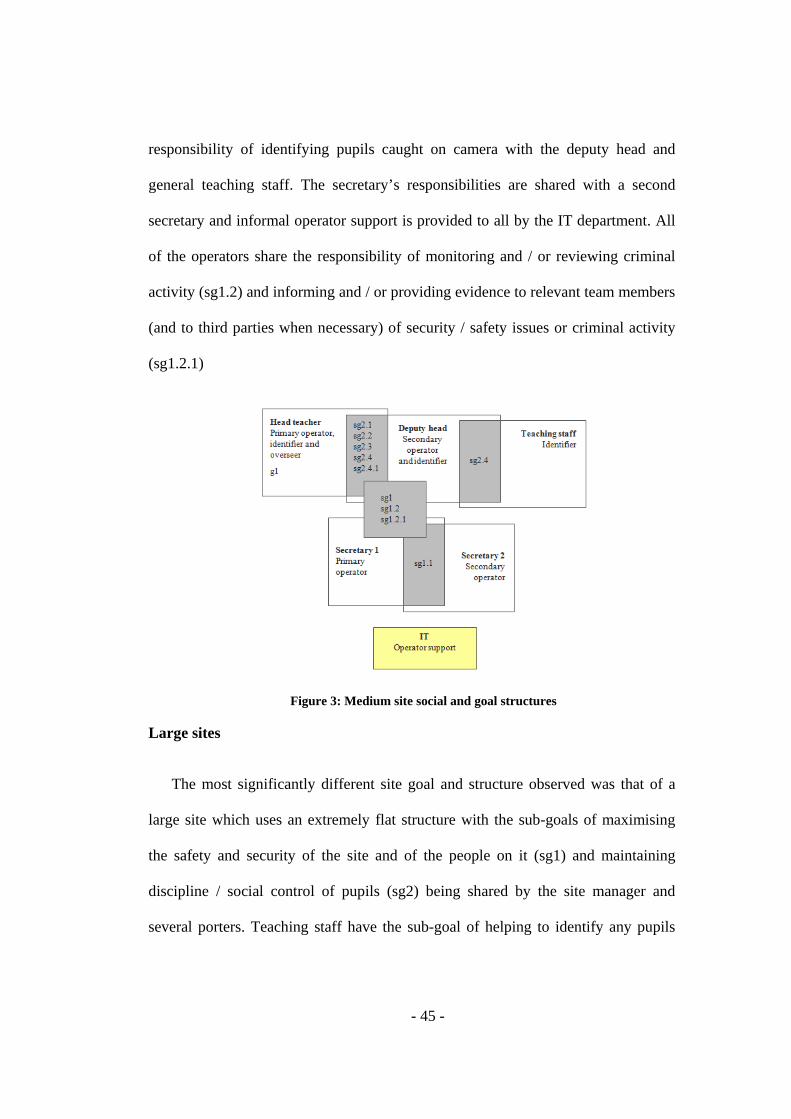
Large sites
The most significantly different site goal and structure observed was that of a
large site which uses an extremely flat structure with the sub-goals of maximising
the safety and security of the site and of the people on it (sg1) and maintaining
discipline / social control of pupils (sg2) being shared by the site manager and
several porters. Teaching staff have the sub-goal of helping to identify any pupils
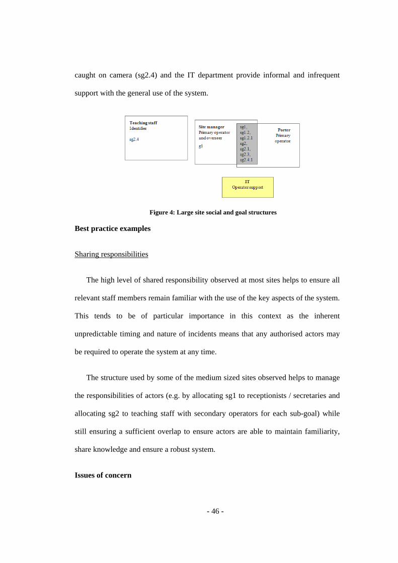
- 46 -
caught on camera (sg2.4) and the IT department provide informal and infrequent
support with the general use of the system.
Figure 4: Large site social and goal structures
Best practice examples
Sharing responsibilities
The high level of shared responsibility observed at most sites helps to ensure all
relevant staff members remain familiar with the use of the key aspects of the system.
This tends to be of particular importance in this context as the inherent
unpredictable timing and nature of incidents means that any authorised actors may
be required to operate the system at any time.
The structure used by some of the medium sized sites observed helps to manage
the responsibilities of actors (e.g. by allocating sg1 to receptionists / secretaries and
allocating sg2 to teaching staff with secondary operators for each sub-goal) while
still ensuring a sufficient overlap to ensure actors are able to maintain familiarity,
share knowledge and ensure a robust system.
Issues of concern

- 47 -
Loss of knowledge with infrequent tasks
There is a high level of dependency by main actors (e.g. head teachers / teaching
staff and secretaries) on support actors e.g. caretaker, IT or the supplier for
understanding of how to carry out certain infrequently performed tasks e.g. copying
incidents to disk. A lack of availability or knowledge by support staff results in an
inability to complete the task. Further training or system redesign may be required
(e.g. improved usability of relevant parts of the system, access to online / integrated
help or additional training).
4.4. Information Flow Model
This model, from the existing DiCoT framework, describes the information
flows that exist in the activity of monitoring / reviewing individuals and their
activities using CCTV in terms of the communication channels among actors and of
the key flow properties. I scoped the analysis around the main similarities and
differences amongst the three site sizes observed (i.e. small, medium and large).
The high-level function of CCTV within schools is to monitor / review the
activity of individuals within and around the school in the interest of safety, security
and discipline / social control. This is illustrated in an input-output diagram shown
in Figure 5 below.

- 48 -
Figure 5: Input-output diagram
Communication channels
Figure 6 below shows the main information flows in monitoring / reviewing
individuals’ activity in small sized sites, table 6 describes each actor and their role in
more detail and table 7 summarises the corresponding communication channels and
communication mechanisms used.
Figure 6: Small site communication channels
Table 6: Small site actors and roles Label Actor Role S1 Secretary 1 Verify identity of site visitors and provide / deny site access
Monitor / review pupil conduct and other criminal activity Inform senior staff or third parties of incidents when necessary and provide video evidence

- 49 -
S2 Secretary 2 Provide support to secretary 1 CT Caretaker Provide support to secretary 1 HT Head teacher Identify visitors and pupils caught misbehaving
Receive notification from operators, police or parents / guardians of incidents Inform operators of incidents to be reviewed Inform police or parents / guardians of incidents to be investigated further
DH Deputy head Provide support to head teacher OT Other teachers Provide support to head and deputy head Pol Police Inform operators or teaching staff of local area incidents which may
have been captured by the school CCTV cameras Receive notification from operators or teaching staff of incidents to be investigated Receive evidence from operators or teaching staff of incidents to be investigated
PG Parent or Guardian
Inform operators or teaching staff of incidents that their children many have been involved in Receive notification from operators or teaching staff of incidents to be investigated Receive evidence from operators or teaching staff of incidents to be investigated
Table 7: Small site communication channels Process Summary Mechanism I Secretary 1 to secretary 2
Secretary 1 (primary operator) indicates to secretary 2 (secondary operator) that a shift handover or help in operating the CCTV system is needed. The vast majority of their working time is spent working side by side in the same room.
Face-to-face, verbal, shouting, gesture

- 50 -
II Secretary 1 to caretaker
Further technical support is provided to the primary secretary by the caretaker.
Verbal, face-to-face, telephone
III Secretary 1 to teaching staff
The secretary informs the teaching staff of any pupil misconduct or criminal activity observed on camera. Teaching staff also alert the secretary of any incidents that need to be either followed on camera (while they are happening) or reviewed (if they have already occurred).
Face-to-face, telephone, email, gesture
IV Teaching staff to police
Teaching staff inform the police (if necessary) of incidents that need to be investigated further e.g. thefts or other criminal activity. In the case of non-school related incidents, the police also contact the teaching staff to find out if incidents have been picked up by the schools cameras.
Telephone, in writing
V Teaching staff to parents / guardians
In the case of pupil related incidents, teaching staff inform parents / guardians (if necessary) of incidents that need to be investigated further.
Telephone, in writing
VI Police to secretary 1
The police then contact the school to follow up on the incident e.g. to provide crime reference numbers and to obtain any available evidence such as CCTV footage or forensic data.
Face-to-face, telephone, gesture
VII Parents / guardians to secretary 1
If parents / guardians have been informed of pupil related incidents, arrangements are made with the school to follow up on the incident e.g. to view any available CCTV footage.
Face-to-face, telephone, gesture
Figure 7 below shows the main information flows in monitoring / reviewing
individuals’ activity in medium sized sites, table 8 describes each actor and their
role in more detail and table 9 summarises the corresponding communication
channels and communication mechanisms used.

- 51 -
Figure 7: Medium site communication channels
Table 8: Medium site actors and roles Label Actor Role S1 Secretary 1 Verify identity of site visitors and provide / deny site access
Monitor / review pupil conduct and other criminal activity Inform senior staff or third parties of incidents when necessary and provide video evidence
S2 Secretary 2 Provide support to secretary 1 IT IT department Provide support to secretary 1 HT Head teacher Identify visitors and pupils caught misbehaving
Receive notification from operators, police or parents / guardians of incidents Inform operators of incidents to be reviewed Inform police or parents / guardians of incidents to be investigated further
DH Deputy head Provide support to head teacher OT Other teachers Provide support to head and deputy head Pup Pupils Inform operators or teaching staff of incidents e.g. theft of personal
property Pol Police Inform operators or teaching staff of local area incidents which may
have been captured by the school CCTV cameras Receive notification from operators or teaching staff of incidents to be investigated Receive evidence from operators or teaching staff of incidents to be investigated
PG Parent or Guardian
Inform operators or teaching staff of incidents that their children many have been involved in Receive notification from operators or teaching staff of incidents to be investigated Receive evidence from operators or teaching staff of incidents to be investigated
Table 9: Medium site communication channels Process Summary Mechanism I Secretary 1 to secretary 2
Secretary 1 (primary operator for providing / denying site access to visitors) indicates through informal communication to secretary 2 (secondary operator) that a shift handover or help in operating the CCTV system is needed. The time spent working alongside each other is extremely limited with most responsibilities being handled independently by secretary 1.
Face-to-face, verbal, shouting, gesture
II Secretaries to IT department
Further technical support is provided to the secretary by the caretaker.
Verbal, face-to-face, telephone
III The secretary informs the teaching staff of any pupil Face-to-face, telephone,
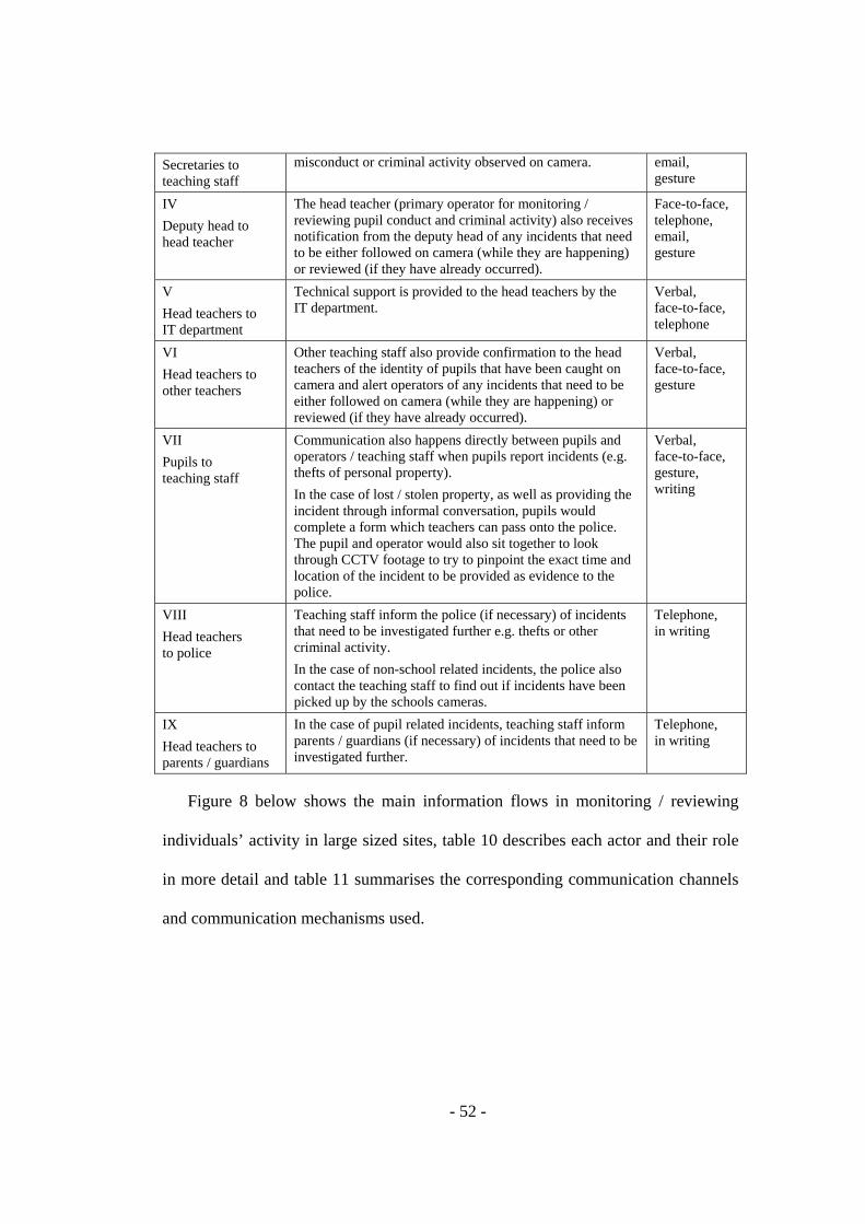
- 52 -
Secretaries to teaching staff
misconduct or criminal activity observed on camera. email, gesture
IV Deputy head to head teacher
The head teacher (primary operator for monitoring / reviewing pupil conduct and criminal activity) also receives notification from the deputy head of any incidents that need to be either followed on camera (while they are happening) or reviewed (if they have already occurred).
Face-to-face, telephone, email, gesture
V Head teachers to IT department
Technical support is provided to the head teachers by the IT department.
Verbal, face-to-face, telephone
VI Head teachers to other teachers
Other teaching staff also provide confirmation to the head teachers of the identity of pupils that have been caught on camera and alert operators of any incidents that need to be either followed on camera (while they are happening) or reviewed (if they have already occurred).
Verbal, face-to-face, gesture
VII Pupils to teaching staff
Communication also happens directly between pupils and operators / teaching staff when pupils report incidents (e.g. thefts of personal property). In the case of lost / stolen property, as well as providing the incident through informal conversation, pupils would complete a form which teachers can pass onto the police. The pupil and operator would also sit together to look through CCTV footage to try to pinpoint the exact time and location of the incident to be provided as evidence to the police.
Verbal, face-to-face, gesture, writing
VIII Head teachers to police
Teaching staff inform the police (if necessary) of incidents that need to be investigated further e.g. thefts or other criminal activity. In the case of non-school related incidents, the police also contact the teaching staff to find out if incidents have been picked up by the schools cameras.
Telephone, in writing
IX Head teachers to parents / guardians
In the case of pupil related incidents, teaching staff inform parents / guardians (if necessary) of incidents that need to be investigated further.
Telephone, in writing
Figure 8 below shows the main information flows in monitoring / reviewing
individuals’ activity in large sized sites, table 10 describes each actor and their role
in more detail and table 11 summarises the corresponding communication channels
and communication mechanisms used.
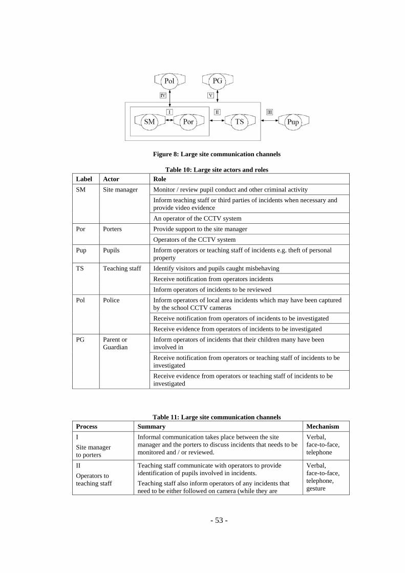
- 53 -
Figure 8: Large site communication channels
Table 10: Large site actors and roles Label Actor Role SM Site manager Monitor / review pupil conduct and other criminal activity
Inform teaching staff or third parties of incidents when necessary and provide video evidence An operator of the CCTV system
Por Porters Provide support to the site manager Operators of the CCTV system
Pup Pupils Inform operators or teaching staff of incidents e.g. theft of personal property
TS Teaching staff Identify visitors and pupils caught misbehaving Receive notification from operators incidents Inform operators of incidents to be reviewed
Pol Police Inform operators of local area incidents which may have been captured by the school CCTV cameras Receive notification from operators of incidents to be investigated Receive evidence from operators of incidents to be investigated
PG Parent or Guardian
Inform operators of incidents that their children many have been involved in Receive notification from operators or teaching staff of incidents to be investigated Receive evidence from operators or teaching staff of incidents to be investigated
Table 11: Large site communication channels Process Summary Mechanism I Site manager to porters
Informal communication takes place between the site manager and the porters to discuss incidents that needs to be monitored and / or reviewed.
Verbal, face-to-face, telephone
II Operators to teaching staff
Teaching staff communicate with operators to provide identification of pupils involved in incidents. Teaching staff also inform operators of any incidents that need to be either followed on camera (while they are
Verbal, face-to-face, telephone, gesture
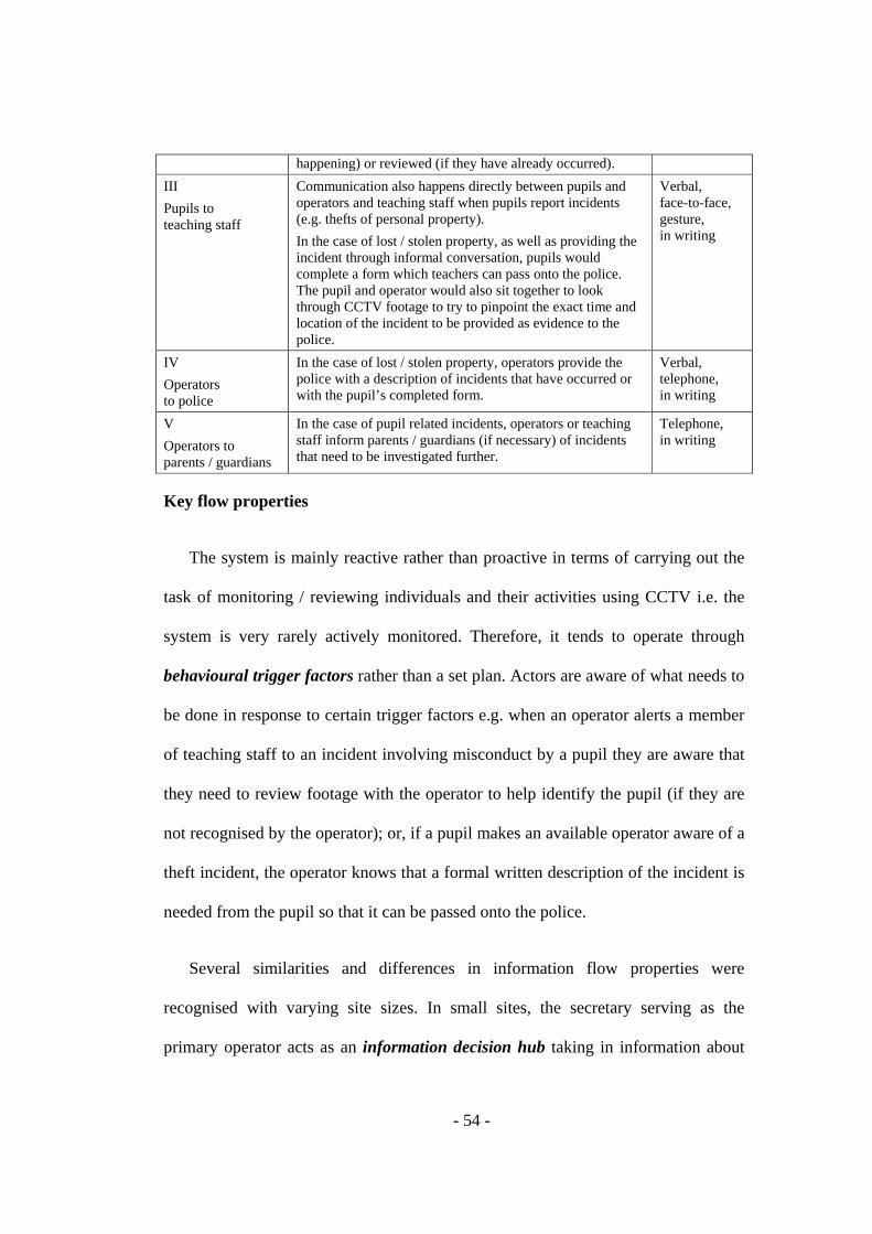
- 54 -
happening) or reviewed (if they have already occurred). III Pupils to teaching staff
Communication also happens directly between pupils and operators and teaching staff when pupils report incidents (e.g. thefts of personal property). In the case of lost / stolen property, as well as providing the incident through informal conversation, pupils would complete a form which teachers can pass onto the police. The pupil and operator would also sit together to look through CCTV footage to try to pinpoint the exact time and location of the incident to be provided as evidence to the police.
Verbal, face-to-face, gesture, in writing
IV Operators to police
In the case of lost / stolen property, operators provide the police with a description of incidents that have occurred or with the pupil’s completed form.
Verbal, telephone, in writing
V Operators to parents / guardians
In the case of pupil related incidents, operators or teaching staff inform parents / guardians (if necessary) of incidents that need to be investigated further.
Telephone, in writing
Key flow properties
The system is mainly reactive rather than proactive in terms of carrying out the
task of monitoring / reviewing individuals and their activities using CCTV i.e. the
system is very rarely actively monitored. Therefore, it tends to operate through
behavioural trigger factors rather than a set plan. Actors are aware of what needs to
be done in response to certain trigger factors e.g. when an operator alerts a member
of teaching staff to an incident involving misconduct by a pupil they are aware that
they need to review footage with the operator to help identify the pupil (if they are
not recognised by the operator); or, if a pupil makes an available operator aware of a
theft incident, the operator knows that a formal written description of the incident is
needed from the pupil so that it can be passed onto the police.
Several similarities and differences in information flow properties were
recognised with varying site sizes. In small sites, the secretary serving as the
primary operator acts as an information decision hub taking in information about
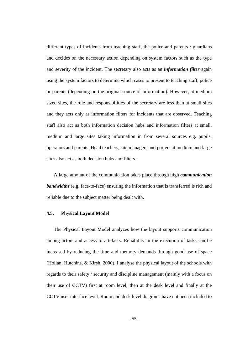
- 55 -
different types of incidents from teaching staff, the police and parents / guardians
and decides on the necessary action depending on system factors such as the type
and severity of the incident. The secretary also acts as an information filter again
using the system factors to determine which cases to present to teaching staff, police
or parents (depending on the original source of information). However, at medium
sized sites, the role and responsibilities of the secretary are less than at small sites
and they acts only as information filters for incidents that are observed. Teaching
staff also act as both information decision hubs and information filters at small,
medium and large sites taking information in from several sources e.g. pupils,
operators and parents. Head teachers, site managers and porters at medium and large
sites also act as both decision hubs and filters.
A large amount of the communication takes place through high communication
bandwidths (e.g. face-to-face) ensuring the information that is transferred is rich and
reliable due to the subject matter being dealt with.
4.5. Physical Layout Model
The Physical Layout Model analyzes how the layout supports communication
among actors and access to artefacts. Reliability in the execution of tasks can be
increased by reducing the time and memory demands through good use of space
(Hollan, Hutchins, & Kirsh, 2000). I analyse the physical layout of the schools with
regards to their safety / security and discipline management (mainly with a focus on
their use of CCTV) first at room level, then at the desk level and finally at the
CCTV user interface level. Room and desk level diagrams have not been included to
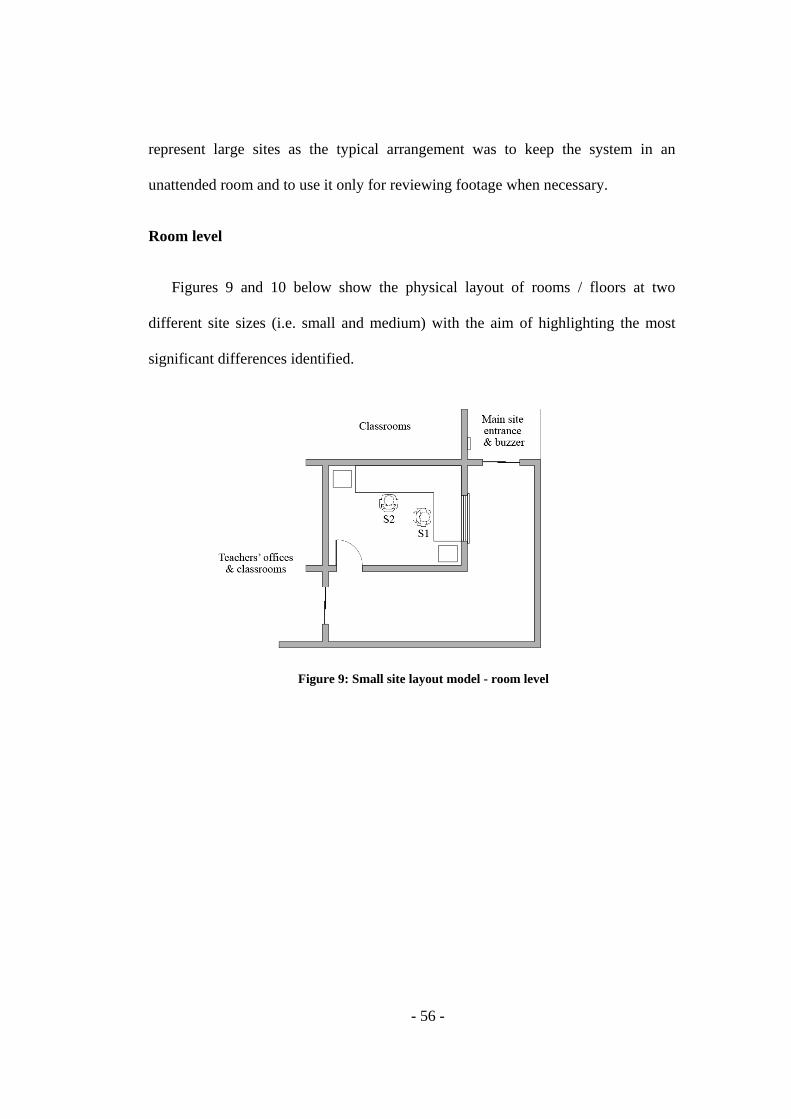
- 56 -
represent large sites as the typical arrangement was to keep the system in an
unattended room and to use it only for reviewing footage when necessary.
Room level
Figures 9 and 10 below show the physical layout of rooms / floors at two
different site sizes (i.e. small and medium) with the aim of highlighting the most
significant differences identified.
Figure 9: Small site layout model - room level
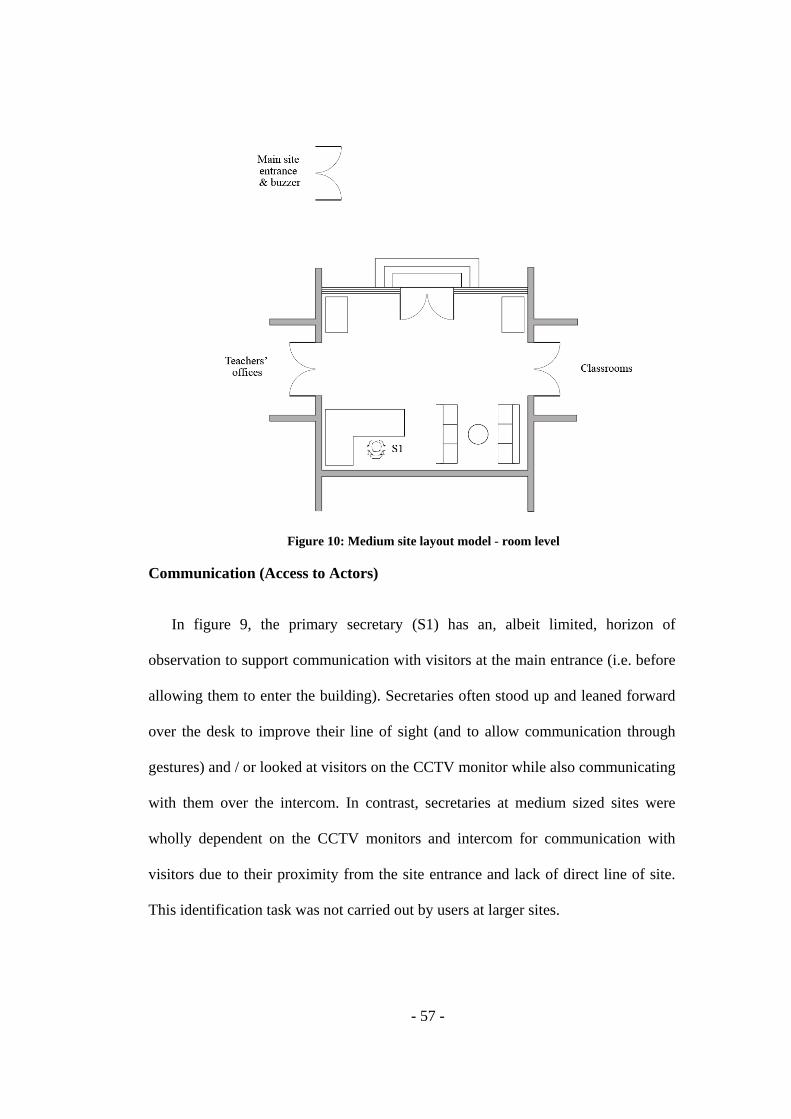
- 57 -
Figure 10: Medium site layout model - room level
Communication (Access to Actors)
In figure 9, the primary secretary (S1) has an, albeit limited, horizon of
observation to support communication with visitors at the main entrance (i.e. before
allowing them to enter the building). Secretaries often stood up and leaned forward
over the desk to improve their line of sight (and to allow communication through
gestures) and / or looked at visitors on the CCTV monitor while also communicating
with them over the intercom. In contrast, secretaries at medium sized sites were
wholly dependent on the CCTV monitors and intercom for communication with
visitors due to their proximity from the site entrance and lack of direct line of site.
This identification task was not carried out by users at larger sites.

- 58 -
With regards to communication amongst staff, the physical layout in small sites
supports quick and informal verbal and gesture communication between the primary
secretary (S1) and the secondary secretary (S2). This enables easy knowledge
sharing between the two actors who share several responsibilities. Communication
between the secretaries and other staff is less well supported by the physical layout
however, the reception serves as a point that secretaries and senior staff can convene
with the necessary security and privacy to discuss security and discipline related
issues. The less open layout also provides the secretaries with a degree of freedom
when working with confidential pupil data while also allowing the information to be
kept secure from unauthorised individuals.
Similarly, it could be argued that the layout in medium sized sites doesn't
support quick / easy face-to-face communication between reception and teaching
staff or amongst staff because of the closed rooms /offices however, the close
proximity of the rooms ensures that face-to-face communications is possible if
necessary. A similar scenario occurs in large sites however, with greater distance
between rooms / offices actors are more dependent on artefact such as phone and
email to support information propagation.
Access to Artefacts
At most of the sites, in the event of an incident that needs to be reviewed,
operators (e.g. secretaries / administrators / site managers / porters), teaching staff
and third parties such as police or parents tend to meet around the CCTV monitor to
discuss the relevant footage. In most cases, although multiple installations of the
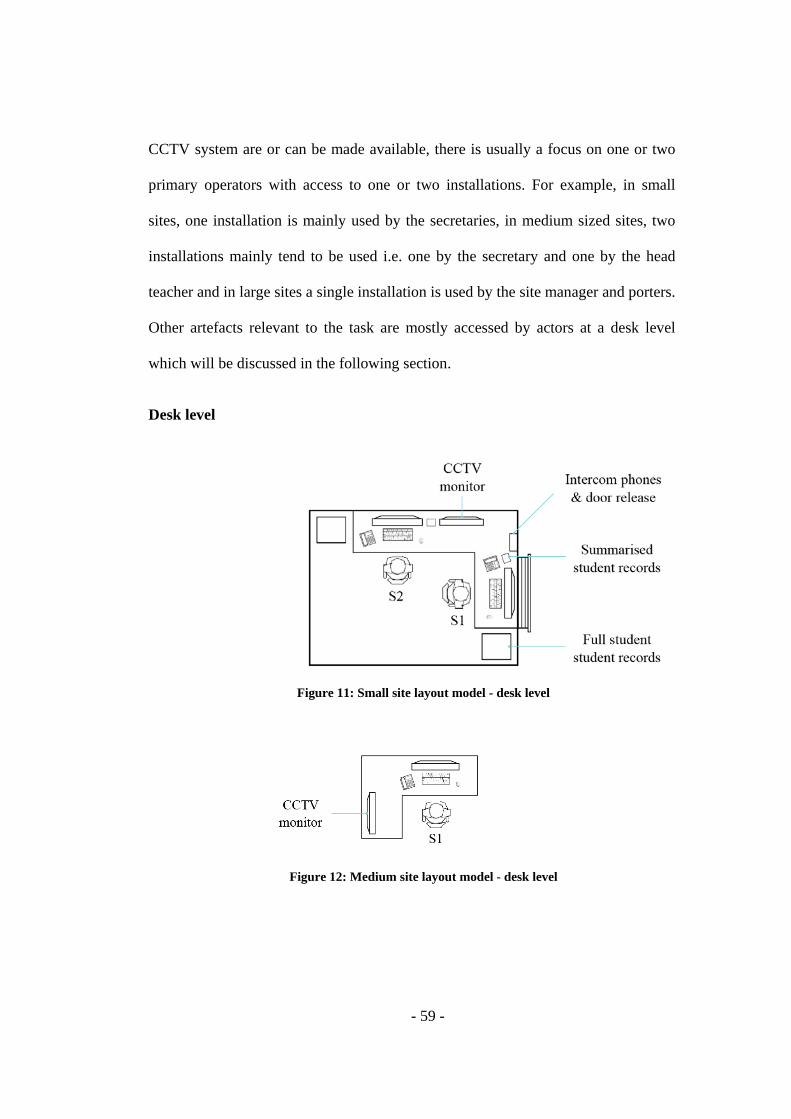
- 59 -
CCTV system are or can be made available, there is usually a focus on one or two
primary operators with access to one or two installations. For example, in small
sites, one installation is mainly used by the secretaries, in medium sized sites, two
installations mainly tend to be used i.e. one by the secretary and one by the head
teacher and in large sites a single installation is used by the site manager and porters.
Other artefacts relevant to the task are mostly accessed by actors at a desk level
which will be discussed in the following section.
Desk level
Figure 11: Small site layout model - desk level
Figure 12: Medium site layout model - desk level
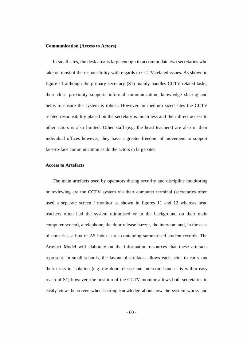
- 60 -
Communication (Access to Actors)
In small sites, the desk area is large enough to accommodate two secretaries who
take on most of the responsibility with regards to CCTV related issues. As shown in
figure 11 although the primary secretary (S1) mainly handles CCTV related tasks,
their close proximity supports informal communication, knowledge sharing and
helps to ensure the system is robust. However, in medium sized sites the CCTV
related responsibility placed on the secretary is much less and their direct access to
other actors is also limited. Other staff (e.g. the head teachers) are also in their
individual offices however, they have a greater freedom of movement to support
face-to-face communication as do the actors in large sites.
Access to Artefacts
The main artefacts used by operators during security and discipline monitoring
or reviewing are the CCTV system via their computer terminal (secretaries often
used a separate screen / monitor as shown in figures 11 and 12 whereas head
teachers often had the system minimised or in the background on their main
computer screen), a telephone, the door release buzzer, the intercom and, in the case
of nurseries, a box of A5 index cards containing summarised student records. The
Artefact Model will elaborate on the information resources that these artefacts
represent. In small schools, the layout of artefacts allows each actor to carry out
their tasks in isolation (e.g. the door release and intercom handset is within easy
reach of S1) however, the position of the CCTV monitor allows both secretaries to
easily view the screen when sharing knowledge about how the system works and
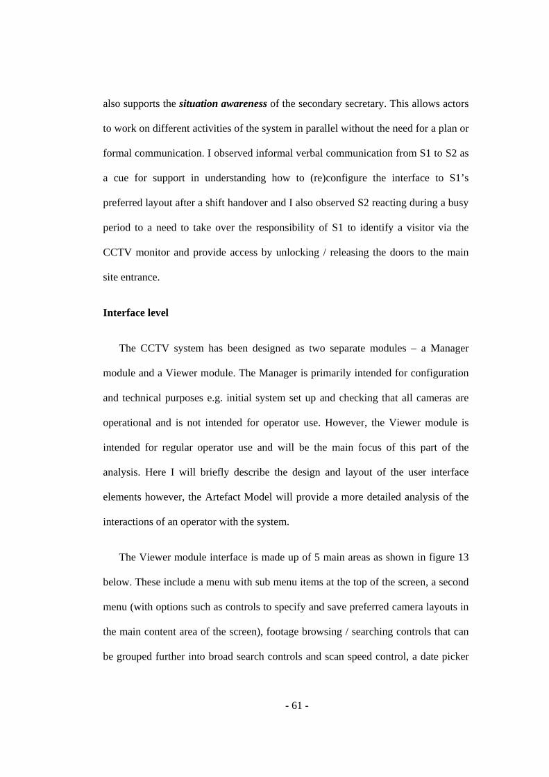
- 61 -
also supports the situation awareness of the secondary secretary. This allows actors
to work on different activities of the system in parallel without the need for a plan or
formal communication. I observed informal verbal communication from S1 to S2 as
a cue for support in understanding how to (re)configure the interface to S1’s
preferred layout after a shift handover and I also observed S2 reacting during a busy
period to a need to take over the responsibility of S1 to identify a visitor via the
CCTV monitor and provide access by unlocking / releasing the doors to the main
site entrance.
Interface level
The CCTV system has been designed as two separate modules – a Manager
module and a Viewer module. The Manager is primarily intended for configuration
and technical purposes e.g. initial system set up and checking that all cameras are
operational and is not intended for operator use. However, the Viewer module is
intended for regular operator use and will be the main focus of this part of the
analysis. Here I will briefly describe the design and layout of the user interface
elements however, the Artefact Model will provide a more detailed analysis of the
interactions of an operator with the system.
The Viewer module interface is made up of 5 main areas as shown in figure 13
below. These include a menu with sub menu items at the top of the screen, a second
menu (with options such as controls to specify and save preferred camera layouts in
the main content area of the screen), footage browsing / searching controls that can
be grouped further into broad search controls and scan speed control, a date picker

- 62 -
and a main content area that displays cameras in either a default or specified layout.
The broad search controls can be used to very quickly jump from one point in the
day to another while the scan speed controls allow the user to enable or stop hand
free (or automatic) play of the footage and to adjust the play speed by displaying
either every frame or every 2, 4, 8, 16, 32 or 64 frames.
Each camera view in the main content area contains a number of options related
to that view / image for example options to save, print or copy an image, an option
to view the current activity on a camera, the option to switch to a zoom mode and
controls to minimise or maximise the window.
Figure 13: Viewer module main screen
Figures 14 to 15 below show the interface elements for each Viewer module
screen that can be accessed from the second menu. Figure 14 shows the ‘Layouts’
menu that is displayed as a small pop up window. It is divided into two main areas.
The top of the window shows the current layout that is being used, the left hand side
Menu 1Menu 2
Main content area
Play and browse controls Date picker
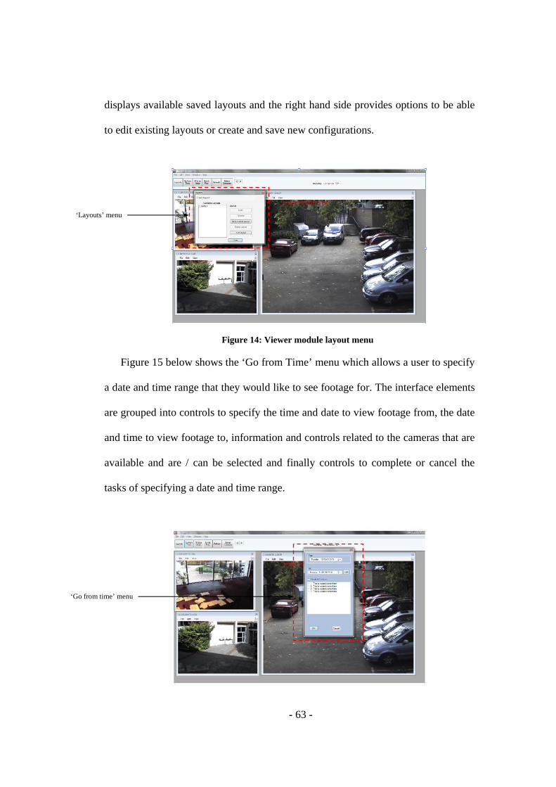
- 63 -
displays available saved layouts and the right hand side provides options to be able
to edit existing layouts or create and save new configurations.
Figure 14: Viewer module layout menu
Figure 15 below shows the ‘Go from Time’ menu which allows a user to specify
a date and time range that they would like to see footage for. The interface elements
are grouped into controls to specify the time and date to view footage from, the date
and time to view footage to, information and controls related to the cameras that are
available and are / can be selected and finally controls to complete or cancel the
tasks of specifying a date and time range.
‘Layouts’ menu
‘Go from time’ menu

- 64 -
Figure 15: Viewer module 'go from time' menu
Figure 16 shows the ‘Synch Play’ mode. When in this state, users are able to
review activity from more than one camera simultaneously. As you can see below,
the second menu is replaced by a red strip that provides options to browse footage,
to copy footage to disk and to exit the synch play mode.
Figure 16: Viewer module synch play mode
In figure 17 you can see the ‘Select Cameras’ menu which displays options to
select / deselect available cameras and controls to either complete or cancel the task.
Figure 17: Viewer module 'select cameras' menu
‘Synch play’ andfootage copying / CD
burning controls
‘Select cameras’ menu
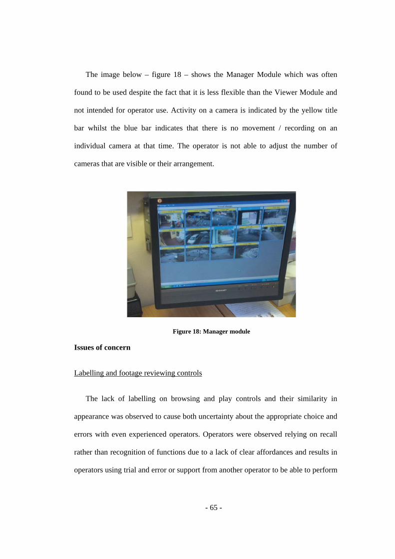
- 65 -
The image below – figure 18 – shows the Manager Module which was often
found to be used despite the fact that it is less flexible than the Viewer Module and
not intended for operator use. Activity on a camera is indicated by the yellow title
bar whilst the blue bar indicates that there is no movement / recording on an
individual camera at that time. The operator is not able to adjust the number of
cameras that are visible or their arrangement.
Figure 18: Manager module
Issues of concern
Labelling and footage reviewing controls
The lack of labelling on browsing and play controls and their similarity in
appearance was observed to cause both uncertainty about the appropriate choice and
errors with even experienced operators. Operators were observed relying on recall
rather than recognition of functions due to a lack of clear affordances and results in
operators using trial and error or support from another operator to be able to perform
- 66 -
tasks such as changing the layout of the screen and browsing while reviewing
footage. However, operators felt willing and able to use this type of interaction
strategy as they felt the consequence of an error would not be severe.
Access to camera views
The main content area in the Viewer module is sufficient for viewing very few
cameras at once but offers poor support for monitoring or reviewing many cameras
due to limited screen space. Users at medium and large sites were often found to be
using the Manager module when carrying out monitoring tasks. Several operators
commented that it gave them a good overview of camera activity and gave them
quick access to all cameras.
Other issues
Operators were observed experiencing difficulty when trying to find functions
such as saving or copying images from individual camera views and trying to zoom
in / out of footage. They were also uncertain of the unconventional arrangement and
representation of minimise and maximise controls.
The grouping of synch play and 'copy to CD' controls does not give a clear
indication of available affordances and of the necessary steps to complete each task.
When searching for a means to copy footage to CD, even after selecting the synch
play option, all operators (except for one) was observed being unable to see how to
begin the task. After being shown how to begin, most operators (both experienced
and inexperienced) were still unable to complete the task of copying footage to CD.

- 67 -
4.6. Artefact Model
The artefact model analyses how artefacts, representations, and tools are used to
store transform and communicate information (Furniss & Blandford, 2010) and how
they aid the coordination of resources.
I analyse the interaction of an operator with the main artefacts involved in the
activities of reviewing CCTV footage and copying footage to CD. The main
artefacts used in these activities in the context of schools are notes (i.e. written notes
made by the operator), a phone and the CCTV system. As a part of the Artefact
Model, both Webb (2008) and Rajkomar (2010) used the Resources Model within
their studies to analyse interactions. Webb used the model to analyse underground
line control staff interaction while Rajkomar extended the model by mapping it to a
state transition diagram in an analysis of a nurse's interaction with key artefacts
during Infusion Administration activity. I use a similar approach to be able to
represent and compare interactions with the CCTV system at sites of different sizes
and to identify and further analyse any incomplete interaction sequences.
I will first briefly discuss the design / use of notes and phones in terms of best
practices and any issues of concern identified before providing a detailed description
of the coordination of resources using the CCTV system.
Best practice examples
In the schools observed, notes were occasionally used to simplify cognitive tasks
by creating a reminder of where an operator was in a task, as external scaffolding.

- 68 -
For example, at one of the schools that visited, during an interruption the main
secretary was observed making a quick note of the time that she had browsed to
while reviewing footage to allow her to quickly return to the same point later. Notes
were also found to be used to support operators in acting as a buffer in the system
by again allowing them to record precise times and dates of an indentified incident
to be able to report / discuss these with senior staff or third parties at an appropriate
or opportune moment. Phones were also used by operators in order to support the
propagation of information around the system. For example, after finding students
involved in an incident on the CCTV system, operators would often call a senior
member of staff (e.g. head teacher) to identify the pupils concerned.
Issues of concern
While notes are a useful and valuable artefact to support activity within the
system, their lack of durability and confidentiality are of concern in a security and
personal / sensitive data environment such as a school.
Coordination of resources
The Resources Model
The Resources Model developed by Wright, Fields & Harrison (2000) defines a
limited number of resource types as abstract information structures that can be used
to analyse interaction and account for decisions and actions. Rajkomar (2010)
proposed thinking of the Resources Model in terms of state transitions. I will briefly
describe the steps that I took in adopting a similar approach to analyse and compare

- 69 -
interaction episodes at different sites and I will also provide definitions of the main
concepts of the Resources Model.
Step 1: Identify tasks to be analysed in interaction episodes
Wright et al (2000) describe one of the uses of the Resources Model as a means
of analysing interaction scenarios. They demonstrate this by conducting a
walkthrough of a specific task to allow them to highlight parts of the interaction
where errors or breakdowns might occur. Here I will carry out a walkthrough of a
footage reviewing and copying task.
Step 2: List the system states defining the interaction sequence
A state is a specific collection of relevant values of objects featuring in an
interaction and Rajkomar (2010) defines a change in state as the resource
configuration change delineating one step in the interaction sequence.
Step 3: List all steps involved in the transition from one state to the next and, where
appropriate, describe each step in terms of:
• the goal – a desired / required state of the system
• the plan – a sequence of actions or states that could be carried out to
complete a task
• affordances – next possible actions from a specific state
- 70 -
• action-effect relations – the contributing connection between an action
and a state
• the history – the actions or states already achieved in the sequence
Step 4: Compare interaction episodes from different sites
Step 5: Evaluate reasons for alternative interaction sequences, errors or incomplete
interactions.
Task: Reviewing and recording CCTV footage
The first task considered is reviewing CCTV footage. The objective is to locate a
specific incident that the operator has been made aware of and to record information
to share with relevant stakeholders. To achieve this, an operator has a pre-computed
plan obtained through training which is represented internally. Therefore the
interaction strategy being used, at the task level, is plan following. At lower sub-task
levels, goal matching or history-based elimination strategies could also be used
depending on resource configurations available at specific points. Figure 19 below
provides an overview of the possible states and interaction sequences.

- 71 -
Figure 19: Interaction sequence overview
The states included in the sequences shown above are:
a. Starting state
b. Appropriate time, date and cameras chosen
c. Incident date chosen
d. Relevant camera views chosen
e. Relevant cameras scanned individually
f. Relevant cameras scanned simultaneously
g. Incident found and recorded
Interaction sequence 1
I will now provide a description of an observed interaction sequence and I will
later describe three variations that were also observed. The system states defining
the first interaction sequence are:

- 72 -
a. Starting state
b. Appropriate time, date and cameras chosen
f. Relevant cameras scanned simultaneously
g Incident found and recorded
Figure 20: Interaction sequence 1
Step 1: Defining the incident date, approximate time and location
The goal of this step is to bring the CCTV footage as close to a point in time
near to a reported incident. After the operator has started the CCTV software, the
operator needs to define the date and time ranges that they are interested in
searching and they must also specify the camera views that they want to look at. The
interaction style used here is goal matching. The set of possibilities are to specify
the desired time, date and camera views within a single modal view or to choose the
desired date and camera views independently before searching through the available
- 73 -
footage for the relevant incident time. The action-effects are that choosing ‘Select
Cameras’ displays a modal window that allows the user to select / deselect
individual camera views. Selecting text within the calendar field makes the text
editable and selecting the calendar icon displays a calendar that allows the date to be
chosen. Alternatively, selecting the ‘Go from Time’ option displays a pop up
window with options to set date and time ranges and camera views in one section. In
this interaction sequence, I will continue to discuss the operator’s interaction with
the ‘Go from Time’ option.
After choosing ‘Go from Time’, the interaction style at this point is plan
following. The plan is externalised in the system interface (see figure 21) by the
modal window. The window also serves as an external representation of the system
state by displaying the date and time currently being viewed along with the camera
views that have already been selected or deselected. The possible actions are the
ability to change the ‘from’ and ‘to’ day, month, year and times individually, the
option to set the ‘to’ criteria for the current date and time and the option to select /
deselect cameras either all at the same time or individually. The action-effects are
that: (1) by clicking the date or time figures in the ‘from’ and ‘to’ fields selects them
and makes them editable, (2) selecting the icon in the right hand corner of the fields
displays a calendar within the modal window to change the date, (3) selecting ‘now’
in the ‘to’ field sets the ‘to’ criteria to the current time and date, (4) when
unchecked, clicking either the ‘check all cameras’ label or check box will select all
available cameras and when checked clicking them will deselect all available
cameras, (5) when unchecked, clicking either the label or check box associated with
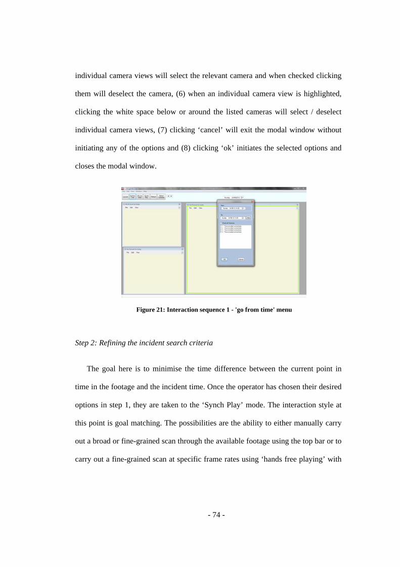
- 74 -
individual camera views will select the relevant camera and when checked clicking
them will deselect the camera, (6) when an individual camera view is highlighted,
clicking the white space below or around the listed cameras will select / deselect
individual camera views, (7) clicking ‘cancel’ will exit the modal window without
initiating any of the options and (8) clicking ‘ok’ initiates the selected options and
closes the modal window.
Figure 21: Interaction sequence 1 - 'go from time' menu
Step 2: Refining the incident search criteria
The goal here is to minimise the time difference between the current point in
time in the footage and the incident time. Once the operator has chosen their desired
options in step 1, they are taken to the ‘Synch Play’ mode. The interaction style at
this point is goal matching. The possibilities are the ability to either manually carry
out a broad or fine-grained scan through the available footage using the top bar or to
carry out a fine-grained scan at specific frame rates using ‘hands free playing’ with

- 75 -
the speed bar as shown in figure 22. The action-effects are the mappings between
pressing the buttons and the resulting system states while in the current state.
Figure 22: Interaction sequence 1 - 'synch play' mode
Step 3: Identifying and recording an incident
While scanning through the footage the operator’s goal is to locate the reported
incident and any individuals involved. The possibilities are to stop the footage at the
relevant point (e.g. to allow the operator to record any relevant information
regarding the incident or to simply allow a senior member of staff to view the
screen), to save or print images from individual camera views or to copy the footage
to CD. As in step 2, the action-effects are the mappings between pressing the
buttons and the resulting system states while in the current state.
Issues of concern
At the initial goal matching stage in step 1, action-effect of the possible actions
could arguably be more clearly communicated as operators find it difficult to
remember the functions performed by less frequently used buttons. For example, the

- 76 -
lack of iconography and alternative text and the use (in some cases) of ambiguous
labels make it difficult for users to predict what individual options will do once
clicked.
After completing step 1, the top tool bar containing the possible actions changes
state to display possible actions associated with searching / scanning through or
recording available footage. This ‘current’ state (as well as how to return to the
previous state) was often unclear to even experienced users. The ‘exit’ option on this
toolbar was also often misinterpreted as an option to exit the application rather than
as an option to exit the current state. Operators were observed using the top right
hand corner ‘x’ to close the system before re-entering to continue with their tasks
rather than exiting the ‘Synch Play’ mode.
Both action-effect and feedback in step 2 were again arguably unclear for the
search bar and speed bar. Although operators were familiar and confident in their
use of the top search bar, they were less certain about the status of the speed bar and
its effects both before using it and while using it. For example, in figure 23 below,
when the search bar is in it’s starting position, pressing the left arrow on the speed
bar or dragging the speed bar’s control to the left will have no effect on the footage
(i.e. as these actions would attempt to rewind even though the available footage is
already in its starting position). Pressing the speed bar’s right arrow three times will
begin to play the footage showing every frame. Pressing the right arrow an
additional 10 times will play the footage at a rate of two frames per second.
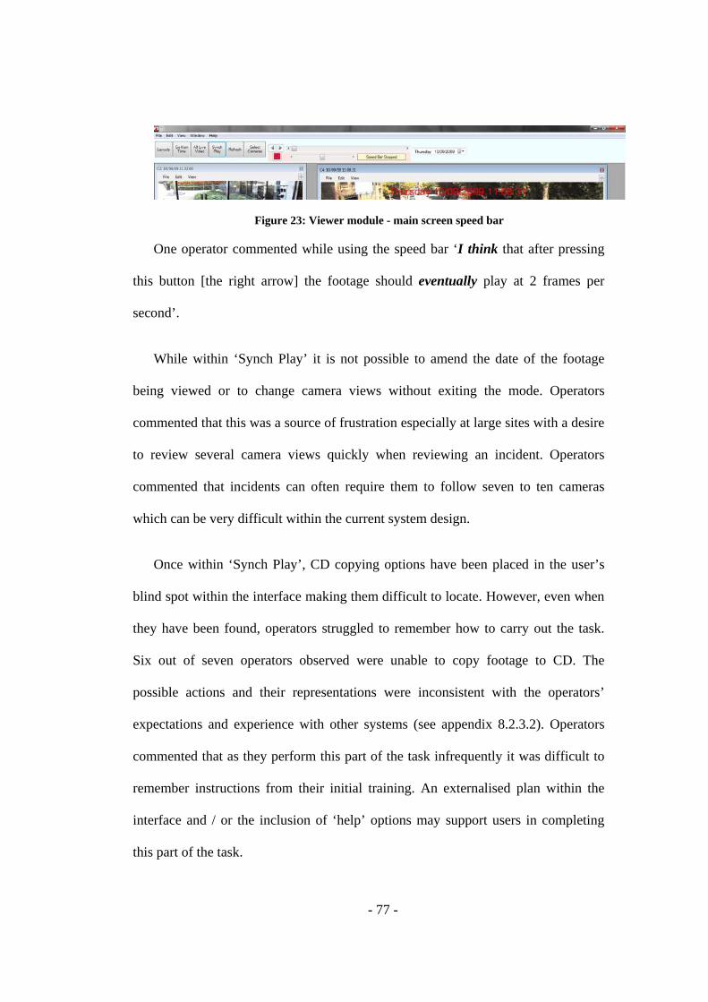
- 77 -
Figure 23: Viewer module - main screen speed bar
One operator commented while using the speed bar ‘I think that after pressing
this button [the right arrow] the footage should eventually play at 2 frames per
second’.
While within ‘Synch Play’ it is not possible to amend the date of the footage
being viewed or to change camera views without exiting the mode. Operators
commented that this was a source of frustration especially at large sites with a desire
to review several camera views quickly when reviewing an incident. Operators
commented that incidents can often require them to follow seven to ten cameras
which can be very difficult within the current system design.
Once within ‘Synch Play’, CD copying options have been placed in the user’s
blind spot within the interface making them difficult to locate. However, even when
they have been found, operators struggled to remember how to carry out the task.
Six out of seven operators observed were unable to copy footage to CD. The
possible actions and their representations were inconsistent with the operators’
expectations and experience with other systems (see appendix 8.2.3.2). Operators
commented that as they perform this part of the task infrequently it was difficult to
remember instructions from their initial training. An externalised plan within the
interface and / or the inclusion of ‘help’ options may support users in completing
this part of the task.

- 78 -
Variations of reviewing task
Variation 1
a. Starting state
b. Appropriate time, date and cameras chosen
e. Relevant cameras scanned individually
g Incident found and recorded
Figure 24: Interaction sequence variation 1
There are variations of the previously described and most commonly used
strategy. In the first alternative sequence (shown in figure 24) the user searches
through the available camera views individually rather than within the ‘Synch Play’
screen.
Issues of concern
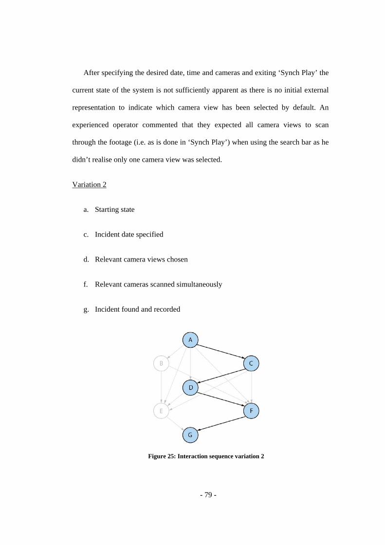
- 79 -
After specifying the desired date, time and cameras and exiting ‘Synch Play’ the
current state of the system is not sufficiently apparent as there is no initial external
representation to indicate which camera view has been selected by default. An
experienced operator commented that they expected all camera views to scan
through the footage (i.e. as is done in ‘Synch Play’) when using the search bar as he
didn’t realise only one camera view was selected.
Variation 2
a. Starting state
c. Incident date specified
d. Relevant camera views chosen
f. Relevant cameras scanned simultaneously
g. Incident found and recorded
Figure 25: Interaction sequence variation 2
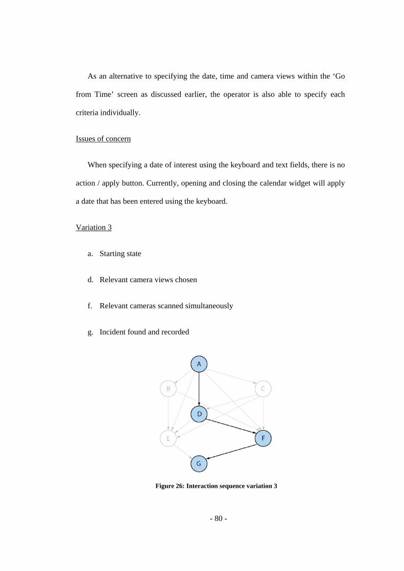
- 80 -
As an alternative to specifying the date, time and camera views within the ‘Go
from Time’ screen as discussed earlier, the operator is also able to specify each
criteria individually.
Issues of concern
When specifying a date of interest using the keyboard and text fields, there is no
action / apply button. Currently, opening and closing the calendar widget will apply
a date that has been entered using the keyboard.
Variation 3
a. Starting state
d. Relevant camera views chosen
f. Relevant cameras scanned simultaneously
g. Incident found and recorded
Figure 26: Interaction sequence variation 3

- 81 -
In the final alternative illustrated above, the first step carried out by the operator
is selecting the camera views of interest before continuing to scan the available
footage for the reported incident. No significant issues were observed or identified
within this sequence.

- 82 -
CHAPTER 5. CONSIDERING DESIGN ALTERNATIVES
Furniss & Blandford, (2010) illustrate how DiCoT can be used to move from
analysis to design and they demonstrate the use of ‘claims analysis’ to consider the
pros and cons of potential design changes. I used this approach to consider several
design alternatives and I have scoped the design process around the Physical Layout
Model (at the interface level) and the Artefact Model. Table 12 below provides a
description of the alternatives considered and provides a reference to wireframes
which can be found in appendix 8.3.1.
Table 12: Design alternatives Design feature Hypothesized Pros (+) or Cons (-) of the Feature Wireframe
reference 1. Include iconography and hint text in the main menu.
+ Serves as a goal resource and as action affordances
n/a
2. Allow camera views to be grouped within the interface according to site locations.
+ Reduces the effort required by users to locate specific camera views by associating their location in the interface to their real world location + Reduces dependency on Manager module by allowing users to use the Viewer module screen space more efficiently and effectively – Potential reduction in the flexibility of searching the interface for cameras for example, will the reduction in effort taken to search for individual cameras increase the effort taken to review multiple cameras in Synch Play?
Figures 30 and 31
3. Flatten the menu hierarchy on camera views and displaying image options as top level menu items.
+ Gives quick access to image saving and printing functions on individual camera views – Reduces the extensibility of the menu area within camera views
n/a
4. Use conventional minimise and maximise representations and physical arrangement on individual camera views.
+ Accelerates the time taken to learn and remember how to use these functions by using familiar (for example ‘browser style’) representations and layouts
n/a
5. Provide external representations to indicate the ability to zoom in and out of camera views.
+ Makes these possible actions easier to discover + Introduces representations that can then be used to support the user in recognising the state of the system with regards to these functions
n/a
6. Keep main toolbar options available while in ‘synch
+ Provides quick access to functions such as changing camera views and the date being viewed
Figure 32

- 83 -
play’ mode while within the Synch Play mode – Displaying irrelevant actions (and all possible actions) while in Synch Play may be overwhelming for users
7. Use familiar iconography and labels alongside the ‘Copy to CD’ controls.
+ Serves as a goal resource and as action affordances
n/a
8. Combine and simplify footage searching and speed bar functions.
+ Improve clarity of possible actions and communication of action effect related associated with searching and ‘hands free’ scanning of footage by using representations that are more familiar to users and consistent with their expectations – Adapting to a redesign may require additional training for users that have become accustomed to the existing design
Figure 33
9. Allow users to bookmark / tag points within footage
+ Allows users to quickly retrieve previously viewed footage at a later date to share with relevant stakeholders or to quickly return to a point of interest after an interruption – Providing quick access to particularly sensitive personal data might be of concern from a security perspective
n/a
10. Include a ‘quick start’ guide within the help section of the interface.
+ Support novices in learning how to use the system + Support more experienced users in remembering how to use the system + Reduce users’ dependency on internal and external support – Would need to be kept up to date with future design / software updates – Would need to take into consideration the diversity of the system’s users for example, language, educational and cultural differences
n/a
11. Highlight the camera view that has been selected by default after specifying time, date and camera view options.
+ Helps users to determine the current state of the system
n/a
12. Allow date criteria to be entered by pressing the enter button on a keyboard after manually entering in the date text field.
+ Improves the system’s accessibility n/a
13. Minimise space used by controls in the interface
+ Maximises the space available to display camera views + Reduces dependency on Manager module by allowing users to use the Viewer module screen space more efficiently and effectively
Figures 34, 35 and 36
14. Incorporate sharing functionality within the system
+ Allow operators to communicate more easily with supporting staff or external stakeholders (i.e. teachers who are ultimately responsible for
n/a

- 84 -
identifying students involved in incidents) at medium to large sites e.g. via email or through an inbox section with notes from operators and a link to relevant footage – Could potentially weaken existing relationships established through face to face communication with external stakeholders such as police and parents – Introduces the risk of sensitive data being accidentally sent to the wrong people / places
15. Allow CCTV to be linked to access doors
+ Allows, from a central location, visibility of where individuals are within the site and provides control over who is in the building (i.e. particularly relevant to large sites using or planning to use electronic locks e.g. proximity sensors, at access doors)
n/a
16. Provide additional training with regards to: - Recording footage to disk - Adjusting the range within which movement is detected by cameras - Decrease sensitivity in picking up motion from objects that are not of interest
+ Reduce dependency by users on external support n/a
- 85 -
CHAPTER 6. GENERAL DISCUSSION
In terms of practical findings, the study has been able to highlight best practices
in the use of CCTV in schools and also identified areas of improvement for the
CCTV system design. In terms of extending distributed cognition analysis, the main
contribution of the research was to apply adaptations of ethnographic techniques
such as personal and rapid ethnography to the existing DiCoT framework so that it
could be used effectively to gather and analyse data across multiple sites in a
relatively short timeframe.
6.1. Assessment of Distributed Cognition
6.1.1. As a methodology for practitioners
The results produced in this study by using a distributed cognition approach
provide support for claims made in the Background chapter i.e. that a distributed
cognition approach is suited to the CCTV context to determine how well the CCTV
system is operating both in terms of its functional capabilities and in terms of
whether or not it is fit for its intended purpose.
A distributed cognition approach provided a means to investigate and observe
the informal role of several actors within the school CCTV context and arguably
supported a better understanding of the efficiency and effectiveness of the system
than would have been obtained using an individual cognition perspective.
While a lot of distributed cognition theory (DCog) is focused on team work
settings, Wright, Fields, & Harrison (2000) describe how relevant DCog is to
- 86 -
evaluating a user’s interaction with a technological artefact. Within this study, it
supported a systematic and detailed evaluation of the system by considering the
information within the technological artefact as well as within the head of the user.
Wright et al (2000) discuss the cognitive engineering approach promoted by
Norman (1986) which is based on the view of cognition as distributed between user
and artefact and the idea that “well designed artefacts could reduce the need for
users to remember large amounts of information while badly designed artefacts
increased the knowledge demands made on the user”.
A traditional view of cognition would argue that the computation of internal and
external representations by a user in their interaction with an artefact requires the
internalisation of the external representations. However, a distributed cognition
perspective argues that this re-representation isn’t needed and that appropriate
external representations can support recognition-based memory or perceptual
judgements rather than recall to reduce task difficulty (Wright et al, 2000, Hutchins,
1995b; Zhang, 1997).
The largest challenges that were faced using DCog in this context were a
dependency on interview data and a lack of observational data. Although the low
volumes of actual observational data and the domain knowledge that needed to be
built up were somewhat anticipated, their severity was underestimated. As a result,
there was a dependency on interviews and walkthroughs with operators while trying
to ensure as high a level of ecological validity as possible. The Preliminary system
evaluation provided a head start in understanding the operator’s potential
interactions with the system. However, the increased domain knowledge highlighted

- 87 -
the need for more structured scenarios and walkthroughs of main tasks to elicit
sufficient data. Difficulty was also faced in gaining access to sites for periods even
as short as an hour which placed pressure on the study timetable structure e.g. it
created difficulty in having an in-depth first phase of visits and shallow second
phase as well as difficulty in getting sufficient time between phases for analysis.
However, the planned rapid DiCoT methodology helped to maximise the time
available. I will expand on the assessment of DiCoT
Introducing (in rapid ethnography terms) informers i.e. the client, a personal
ethnography style preliminary system evaluation and an outline of the desired data
gathering points both with regards to interviews and observations through the use of
DiCoT’s principles and abstract information structures of the Resources Model
helped to manage the challenges mentioned above. I will elaborate of my
assessment of the use of DiCoT’s principles in section 6.2 and on the additions of a
rapid ethnography and personal ethnography approach in section 6.2.3.
6.1.2. As a theory with the scope to extend DiCoT
DCog studies have traditionally taken a longitudinal approach i.e. they consist of
repeated observation and / or interview of the same set of subjects over a long
period of time. While the work of Furniss & Blandford (2006) introduced concepts
from contextual inquiry to DCog, there had been little or no work done with a focus
on reducing time and effort taken for data gathering and analysis from a DCog
perspective. There had also been limited work done prior to Werth (2009) into
investigation multiple sites from a DCog perspective.
- 88 -
As a result, there was little to draw on from previous DCog specific research to
address the challenge of extending DiCoT in terms of its suitability for either rapid
or multisite studies. It seemed appropriate to focus on the evolution of field research
and to continue to draw ideas from contextual inquiry and rapid ethnographic
techniques to extend DiCoT in a way that was sensitive to its origins and its goals as
a methodology rather than a method (i.e. a collection of ideas and concepts that
serve as a support and a basis for data gathering, analysis and design rather than a
step by step plan to be strictly followed).
The potential for a Conceptual Model, on the other hand, was inspired by
cognitive engineering, DCog (i.e. the Resources Model) and examining the use of
mental models as mediating artefacts (Furniss & Blandford, 2006). The abstract
information structures of the Resources Model support a focus on the evolving
configuration of information resources over time and in exploring a Conceptual
Model, I am interested in if they can also provide a means to discuss users’ mental
models within an interaction sequence using DCog terms. The incorporation of a
Conceptual Model would make it possible to be explicit about differences in the
design model, the user’s model and the system image in DCog terms and allow
inferences to be made more easily about the need for redesign, training and / or
facilitate thinking about design alternatives, as has been briefly illustrated in this
study (see appendix 8.2.3.2).
- 89 -
6.2. Assessment of DiCoT
6.2.1. Utility of existing models
DiCoT addresses DCog’s limitations in that it provides focus for data gathering
and gives structure to data analysis. In this study, DiCoT’s principles helped to
know what to look for in the field, how to articulate what was being observed,
review what had been gathered before leaving the field and allowed data to be
systematically analysed and compared across multiple sites. DiCoT allowed areas
for improvement to be identified in terms of process, training and system design and
was critical in supporting the focus that was needed in this rapid research context.
The System Evolution Model provided an insight into the legal obligations of
schools with regards to CCTV and revealed that in some instances access to the
system could be obtained too easily by unauthorised individuals. The Social
Structures Model showed an undesirable dependency on support staff to be able to
carry out some tasks such as copying footage to CD. The Information Flow Model
revealed that the system operates through behavioural triggers with actors being
expected to know what they need to do at relevant moments rather than operating
through a formal plan. The Physical Model considered layout at three levels, namely
the room, desk and interface levels. The room and desk levels didn’t reveal any
areas for improvement. However, the interface level showed that the current layout
doesn’t optimise the space available for users to view a large number of camera
views and revealed that users often rely on the Manager Module rather than the
Viewer Module as they feel it gives them a better overview of activity on several
cameras at any one time. The Artefact Model highlighted a need to make available
- 90 -
actions more apparent in the interface as well as a need for better communication of
action-effect. For example, operators were observed finding it difficult to remember
what functions were performed by individual buttons.
6.2.2. As a methodology to support design
Furniss & Blandford (2010) discuss the different ways DiCoT can support
contextual design, namely understanding the basic mechanics of the system, gaining
deep conceptual insight into how the system works, identifying incremental design
improvements as the analysis progresses, and through using the DiCoT models to
play-out alternative configurations to consider more revolutionary design changes.
Although design alternatives were only considered for the Physical Model at the
interface level and the Artefact Model, a broad range of incremental to more
significant changes were considered. For example, figure 32 illustrates a potential
new screen layout that combines the Synch Play options with other main options.
The motivation for this idea was to allow users (particularly in large sites) to be able
to quickly and easily alter camera views and dates while in Synch Play as the
current design forces users to exit Synch Play to make these changes. Figures 34, 35
and 36 show a potential new design that aims to maximise the screen space available
for arranging camera views and tries to reduce the effort involved in users locating
cameras of interest by grouping cameras according to their real world locations.
Claims analysis was then used to evaluate and make explicit the respective pros and
cons of the proposed changes.
- 91 -
6.2.3. As a methodology to support rapid multisite studies
DiCoT is arguably already a rapid technique through its codifying and
contextual inquiry approach however, there had been no prior work done to explore
its suitability as a methodology to support short duration research. Although no
specific guidance was found in the literature with regards to using DiCoT in this
context, the framework was successfully used to address intense data gathering and
preliminary data analysis from six sites over a relatively short period of two weeks.
Also, DiCoT has predominantly been used in single site studies in the past with
the exception of Werth (2009). In Werth’s study, DiCoT was used to investigate
three Medical Equipment Libraries (MELs) and was able to demonstrate how the
framework can be used to compare MELs across contexts to identify best practices.
In this study, I used DiCoT to explore the use of CCTV in schools and demonstrated
how the framework can be used to allow data from the six sites to be systematically
gathered, compared and analysed to identify best practices as well as areas for
improvement.
No additions were necessary to the DiCoT models to support either rapid or
multiple site investigations. However, several guides and templates were
incorporated throughout the study and ideas were drawn from personal and rapid
ethnography to optimise the data gathering and analysis process as illustrated in
figure 1. I will continue to expand on the additions mentioned.
- 92 -
6.2.3.1. Templates and guides
A structured observation checklist, which integrated the DiCoT principles as a
guide (see table 13), was used to systematically gather observations relevant to the
research goals. In addition, a structured interview checklist which also incorporated
the DiCoT principles (see table 4) was used to identify potential issues of interest for
discussion. A data processing template (see figure 27) was created to systematically
categorise and compare data from all the sites investigated at a DiCoT model level.
6.2.3.2. Adapted personal ethnography
An adapted personal ethnography approach (i.e. an initial evaluation of the
system away from the context) provided insight into possible interactions and tasks
that may have been carried out with the system ensuring that time spent in the field
was used as efficiently as possible. It provided a means to triangulate the research
and to augment the data that would be gathered in the field. It allowed me to make
explicit my interpretations of how the CCTV system functioned and facilitated
discussions with the client in debriefing sessions. Finally, it supported piloting of
planned data gathering to maximise the chances of gathering useful data while in the
field.
6.2.3.3. Adapted rapid ethnography
An adapted rapid ethnography approach with the use of informers helped to
structure the data gathering in a manner that would maximise the chances of
obtaining useful data and also assisted in gaining domain knowledge. Debriefing
- 93 -
sessions helped to validate data throughout the study and to adapt data gathering as
the study progressed. Phased, focused studies ensured that data gathering and
analysis could be kept iterative and adjusted wherever necessary throughout the
study.
Rapid processes are often criticised for reducing the depth of analysis and there
is a major risk that the researcher will lose sight of observations that may be
important to the study objectives. However, contextual inquiry aims to give a
‘reasonable’ understanding of the context being studied and emphasises the need for
clear objectives and focus when conducting rapid field research.
The additions to the framework outlined takes strides towards increasing the
practicality of ethnographic studies in this rapid multisite context by standardising
aspects of the process for example, note taking and analysis. This provides an
opportunity to divide areas of focus in the case of more than one observer in the
field or more than one analyst without reducing DiCoT to a method rather than a
methodology. It aims to provide an understanding of the context across several sites
and useful conclusions to support design within a short space of time as well as a
foundation for similar or lengthier future study.

- 94 -
CHAPTER 7. CONCLUSION
The main aim of the study was to understand CCTV systems in the school
context from a distributed cognition perspective using DiCoT as a framework for
investigation. The secondary aim was to assess the suitability of DiCoT for rapid
multi-site ethnographic studies. The existing models assisted in the critical role of
providing a clear focus for the study while in the field and at the analysis stage.
They also provided a foundation to be able to compare data across sites to arrive at
recommendations for improvements towards efficiency, effectiveness and best
practice. Concepts from personal and rapid ethnography and additional tools in the
form of templates and guides were incorporated into the framework to make both
data gathering and analysis more efficient under the time constraints of the project.
The findings confirm that the whole world environment approach of DCog is
suited to the school CCTV context to be able to understand not only the
effectiveness of the CCTV system as a technological artefact but to be able to
identify whether the system is fit for purpose by studying interactions between the
social and technical system. The growing diversity of CCTV users and the study
findings also provide support in favour of the argument that DCog is relevant to
evaluating a user’s interaction with a technological artefact. The experiences of the
users in their interaction with the CCTV system further highlight that appropriate
external representations can reduce task difficulty and ultimately result in
technological artefacts that are easier to use.
- 95 -
CHAPTER 8. REFERENCES
Beyer, H. and Holtzblatt, K. (1998). Contextual design: defining customer-centered systems. Morgan Kaufmann Publishers Inc., San Francisco, CA, USA.
Blandford, A., Green, T. R., Furniss, D., and Makri, S. (2008). Evaluating system utility and conceptual fit using CASSM. International Journal of Human-Computer Studies, 66(6):393-409.
Button, G. and Sharrock, W., (1995) “Ethnomethodology and HCI”, presentation at the CHI’95 Research Symposium, Denver, Colorado.
Carroll, J. M. (2003). HCI models, theories and frameworks. Oxford: Elsevier Publishing.
Cunningham, S. J. and Jones, M. (2005). Autoethnography: a tool for practice and education. In CHINZ '05: Proceedings of the 6th ACM SIGCHI New Zealand chapter's international conference on Computer-human interaction, pages 1-8, New York, NY, USA. ACM.
Furniss, D. & Blandford, A. (2006). DiCoT: A methodology for applying distributed cognition to the design of teamworking systems. pages 26-38.
Furniss, D. & Blandford, A. (2010) DiCoT Modeling: From Analysis to Design. Proc. CHI 2010 Workshop on Bridging the Gap: Moving from Contextual Analysis to Design.
Hammersley, M. and Atkinson, P. (1995). Ethnography: Principles and Practice. Routledge, 2 edition.
Hollan, J., Hutchins, E., and Kirsh, D. (2000). Distributed cognition: toward a new foundation for human-computer interaction research. ACM Trans. Comput.-Hum. Interact., 7(2):174-196.
Hutchins, E. (1995). How a cockpit remembers its speeds. Cognitive Science, 19:265-288.
Jonassen, D. (1995). Operationalizing mental models: Strategies for assessing mental models to support meaningful learning and design supportive learning environments. In Proceedings of The First International Conference on Computer Support for Collaborative Learning (pp. 182-186). Bloomington, IN.
Keval, H.U. (2009). Effective Design and Configuration of Digital CCTV. PhD thesis, University College London
- 96 -
McCahill, M. and Finn, R. 2010. The Social Impact of Surveillance in Three UK Schools: ‘Angels,’ ‘Devils’ and ‘Teen Mums.’ Surveillance & Society 7(3/4): 273-289
Millen, D. R. (2000). Rapid ethnography: time deepening strategies for HCI field research. In DIS '00: Proceedings of the conference on Designing interactive systems, pages 280-286, New York, NY, USA. ACM Press.
Norman, D.A. (1983) Some observations on Mental Models. In D. Gentner, and A.L. Stevens, eds. Mental Models. Lawrence Erlbaum Associates Inc. pp7-14
Norman, D. A. and Draper, S. W. (1986). User Centered System Design; New Perspectives on Human-Computer Interaction. L. Erlbaum Associates Inc., Hillsdale, NJ, USA.
Rajkomar, A. and Blandford, A. (2012). Understanding infusion administration in the ICU through distributed cognition. Journal of Biomedical Informatics.
Emmeline Taylor (2011): UK schools, CCTV and the Data Protection Act 1998, Journal of Education Policy, 26:1, 1-15
Werth, J. and Furniss, D. (2012). Medical equipment library design: revealing issues and best practice using DiCoT. IHI '12 Proceedings of the 2nd ACM SIGHIT International Health Informatics Symposium, 583-592
Wright, P., Fields, B., and Harrison, M. (1999). Analysing Human-Computer interaction as distributed cognition.

- 97 -
CHAPTER 9. APPENDIX
8.1. Data gathering
Data was gathered using the template shown in table 13 and initially recorded by
making hand written notes on A4 printed copies of the template. Observations and
comments from interviews were supplemented with my own self-reflections and
general thoughts both during and immediately after each visit. The hand written
notes were subsequently word processed within the same template structure.
Table 13: Observation template example Note categories (NC): O ‐ Observation; I ‐ Interview; S ‐ Self‐reflection; T ‐ General thoughts; D ‐ Difficulty; Q ‐ Question; A ‐ Answer; PC ‐ Participant comment
Date: 23.06.2011 Time: 13.30 – 14.45 Site reference: S2 – (no. of cameras)
NC +/– M Notes Models (M) I Ev When was CCTV first introduced into the site? Ev Evolution
19. How has the cognitive system evolved over time?
Sc Social 21. Who are the people involved, their roles and responsibilities? 22. Overlap and the sharing of responsibilities for error checking?
Ph Physical layout 01. Is space used in supporting cognition? 02. Clear mapping of spatial representations? 03. Form match between representations and what is represented? 04. Subtle bodily supports e.g. pointing? 05. What’s going on, happened or planned)? 06. What can be seen or heard by the observed? 07. Access to people, conversations, work, artefacts & physical reps?
IF Information flow 08. What mechanisms allow info to move around the system?
A Ev Operator been at site for ‘X’ years and there were ‘X‐X’ cameras. Has since been updated to ‘X’ cameras.
I Ev Why was it introduced? A Ev Initially introduced because of break‐ins and
stolen items (e.g. lead from the roof) on several occasions.
I Ev Are there any plans to change it or any aspect of the current system in the future?
A Ev The previous system was an analogue system and the cameras were fairly low resolution. The cameras are gradually being changed to higher spec/higher resolution cameras but there is no intention to change the CCTV system.
PC The current system is a complete improvement over the old one. The old system was too complicated to use.
O PC
– Ph01Ph02
Operators use Manager module rather than Viewer module to monitor activity. As a result layout is not customised and there is no mapping between Manager layout and actual building/camera layout.
I Sc What are your goals for CCTV at your site? A Sc (1) Child safety (child monitoring in play areas) –
retrospective investigation of incidents (e.g. children fighting) plus monitoring incidents as alerted to them (e.g. children in areas of the school that they shouldn’t be) (2) Child

- 98 -
monitoring in play areas (3) Theft and intrusion prevention – retrospective review of theft incidents and preparing evidence for the police (i.e. copying footage and images to disk).
09. How are information representations changed? 10. Central point(s) for information channels? 11. Is information ever held up to be used later? 12. How rich are the communications? 13. Are both informal and formal communication used? 14. Are groups of individuals operating without an overall plan?
Ar Artefact 15. Are mediating artefacts used to support activity? 16. Is external scaffolding used to simplify cognitive tasks? 17. Explicit reps of relationship between current state/goal state? 18. Internal / external coordination of resources
20. Expert coupling
Q Ar18 Can you walk me through how you copy footage of a previous incident to CD?
A/O ‐ Ar18 Go to: (1) Viewer (2) Select Camera (3) Go from time (4) Select time and date (5) Press Ok (6) Would expect at this point to be presented with a new window that says ‘Burn to CD’ (7) ‘Synch Play’ (8) Once in ‘Synch Play’ screen interaction sequence broke down as user commented that they would be so unsure of what to do next that they would either call someone for help or simply stop. User hesitant to attempt history‐based strategy as they were concerned about the consequence of any errors (due to poor action‐effect relations) and goal matching not possible due to poor affordances and action‐effect relations. Operator commented that they were trying to think back to the training that they received and the steps that they were advised to follow.
8.1.1. Participant Information Sheet
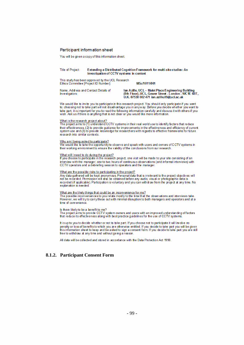
- 99 -
8.1.2. Participant Consent Form

- 100 -
8.2. Data analysis
This section describes how the data that was gathered during observations and
interviews was processed to create the DiCoT models and to support a comparison
of data across multiple sites.
8.2.1. Processing the data
Once the data had been word processed, an excel spreadsheet was used to
categorise the coded data into relevant DiCoT models with a separate worksheet

- 101 -
being used for each model. Each worksheet was structured as illustrated in the
Artefact Model example shown in figure 27 below. The positive and negative rows
allowed data to begin to be organised into positive and negative working practices
while the summary rows allowed me to begin to highlight significant similarities
and differences across sites. Reference to the DiCoT principles were retained within
the data when populating the spreadsheets to further support analysis using the
DiCoT models (for example, a suffix of ‘Ar18’ on a line of data indicated an
association to principle 18 which relates to the Artefact Model. This approach was
extremely useful for organising the data when forming the narrative for each model.
As had been done by Rajkomar (2010), notes with the codes S (self-reflection), D
(difficulty) and T (thought) were classified into either the Method or Discussion
sections depending while notes with the code Q (question) were moved to the
question spreadsheet to be addressed in subsequent site visits.
Figure 27: Data processing template example
8.2.2. Analysis using existing DiCoT models

- 102 -
Once the spreadsheets had been populated, they were reviewed to create a
narrative and a representational diagram (where relevant) for each DiCoT model.
8.2.3. Considering a Conceptual Model
8.2.3.1. Literature review
During the preliminary system evaluation and piloting sessions, it was apparent
that despite reference being made to the use of mental models as mediating artefacts
within the DCog and DiCoT literature (Hutchins, 1995a, p.290; Furniss &
Blandford, 2006), there was no description of how mental models could be
discussed in DCog terms. A brief literature review was carried out to gain a deeper
understanding of mental models and to explore the feasibility of incorporating a
Conceptual Model within this study. Although it was not explored passed the
piloting stage due to project scope, this section provides a brief overview of the
review that was conducted.
Norman (1983) describes mental models as naturally evolving models
formulated by people through interaction with a target system. He explains that they
can be more fragmentary than the term “model” might usually suggest with users
often creating a mental model of parts of a system that bear no resemblance to the
workings of the rest of the system to support them in using it. Farooq & Dominick
(1988) describe mental models as analogical, incomplete, or fragmentary
representations of how a system works and Carley and Palmquist (1992) define
mental models as internal representations that can be represented as networks of
concepts.

- 103 -
Jonassen (1995) states that a conceptual model is a designer’s construct of a
system to show the users how they should visualize the system. Norman (1983)
explains that this conceptual model (which he refers to as the design model) is only
important to the user during learning and trouble-shooting but argues that it is
essential at these stages. Ensuring the conceptual model and mental model are as
close as possible is critical to building a system that is easy to use.
Carroll (2003) presents a range of ideas that pull together several theories on
mental models and begins to discuss them with concepts that are not unfamiliar to
DCog and the Resources Model in particular. Carroll discusses the yoked state space
(YSS) hypothesis by Payne, Squibb and Howes (1990) which states that some
representation of the domain of application of an artefact is required by the user (in
what they refer to as the goal space) in order to problem solve in the device space.
Carroll explains that the two spaces need to be yoked.
More recent work by Blandford, Green, Furniss and Makri (2007) developed
Concept-based Analysis of Surface and Structural Misfits (CASSM), a novel
approach to usability evaluation focusing on conceptual structures rather than users’
tasks. Although CASSM has not been used here, ideas have been drawn from the
approach as will be illustrated in the next section e.g. in indicating if internal and
external representations are present (P), difficult to find (D) or absent from the user
and the interface.
8.2.3.2. Conceptual Model example
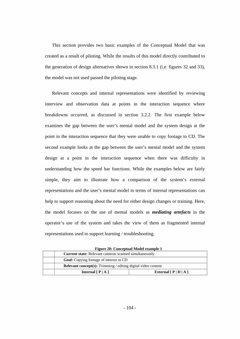
- 104 -
This section provides two basic examples of the Conceptual Model that was
created as a result of piloting. While the results of this model directly contributed to
the generation of design alternatives shown in section 8.3.1 (i.e. figures 32 and 33),
the model was not used passed the piloting stage.
Relevant concepts and internal representations were identified by reviewing
interview and observation data at points in the interaction sequence where
breakdowns occurred, as discussed in section 3.2.2. The first example below
examines the gap between the user’s mental model and the system design at the
point in the interaction sequence that they were unable to copy footage to CD. The
second example looks at the gap between the user’s mental model and the system
design at a point in the interaction sequence when there was difficulty in
understanding how the speed bar functions. While the examples below are fairly
simple, they aim to illustrate how a comparison of the system’s external
representations and the user’s mental model in terms of internal representations can
help to support reasoning about the need for either design changes or training. Here,
the model focuses on the use of mental models as mediating artefacts in the
operator’s use of the system and takes the view of them as fragmented internal
representations used to support learning / troubleshooting.
Figure 28: Conceptual Model example 1 Current state: Relevant cameras scanned simultaneously Goal: Copying footage of interest to CD Relevant concept(s): Trimming / editing digital video content Internal [ P | A ] External [ P | D | A ]

- 105 -
Rep
rese
ntat
ions
• Mark start of CD (P) • Mark end of CD (P) • Start copying (P)
• Mark start of CD (D) • Mark end of CD (D) • Start copying (D)
Not
es
The operator expected to be able to mark the start and end points to be copied to CD and didn’t expect these actions to be linked to the search / scanning control. Although the ‘Mark start of CD copy’ is visible in the interface it arguably isn’t prominent and the action to mark the end of the CD is currently hidden and difficult to find. Although it is possible to mark the end of the CD copy, there is no external representation to indicate that this action is possible at present.
Figure 29: Conceptual Model example 2 Current state: Appropriate time, date and cameras chosen Goal: Scan through available footage on individual cameras Relevant concept(s): Playing audio / visual content online Internal [ P | A ] External [ P | D | A ]
Rep
rese
ntat
ions
• Play (P) • Stop (P) • Forward (P) • Rewind (P) • Speed up / increase frame rate (P) • Slow down / decrease frame rate (P)
• Play (D) • Stop (P) • Forward (P) • Rewind (P) • Speed up / increase frame rate (D) • Slow down / decrease frame rate (D)
Not
es
The existing design combines multiple functions into individual controls making them difficult to discover e.g. play, forward and increase frame rate are represented as a single ‘right facing’ arrow button and; play, rewind and decrease frame rate are represented as a single ‘left facing’ arrow button. Redundancy of all the actions mentioned has also been provided in a single control that can be manually dragged left or right. Representations currently used are also inconsistent with expectations from prior experience and those in the operator’s mental model.
8.3. Considering design alternatives
8.3.1. Wireframes
The wireframes in this section aim to support the description of design
alternatives given in table ‘x’ and they do not intend to serve as final design
solutions. They also only provide a description of layout and functionality
considerations rather than look and feel. A broader range of design alternatives
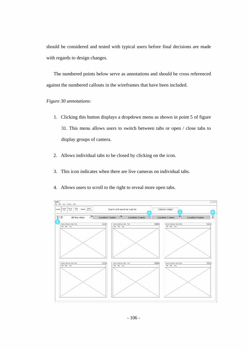
- 106 -
should be considered and tested with typical users before final decisions are made
with regards to design changes.
The numbered points below serve as annotations and should be cross referenced
against the numbered callouts in the wireframes that have been included.
Figure 30 annotations:
1. Clicking this button displays a dropdown menu as shown in point 5 of figure
31. This menu allows users to switch between tabs or open / close tabs to
display groups of camera.
2. Allows individual tabs to be closed by clicking on the icon.
3. This icon indicates when there are live cameras on individual tabs.
4. Allows users to scroll to the right to reveal more open tabs.
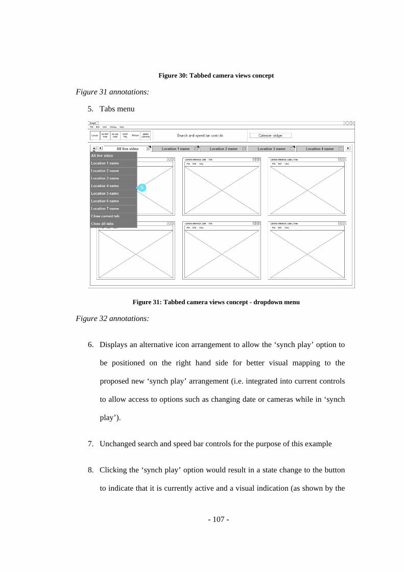
- 107 -
Figure 30: Tabbed camera views concept
Figure 31 annotations:
5. Tabs menu
Figure 31: Tabbed camera views concept - dropdown menu
Figure 32 annotations:
6. Displays an alternative icon arrangement to allow the ‘synch play’ option to
be positioned on the right hand side for better visual mapping to the
proposed new ‘synch play’ arrangement (i.e. integrated into current controls
to allow access to options such as changing date or cameras while in ‘synch
play’).
7. Unchanged search and speed bar controls for the purpose of this example
8. Clicking the ‘synch play’ option would result in a state change to the button
to indicate that it is currently active and a visual indication (as shown by the
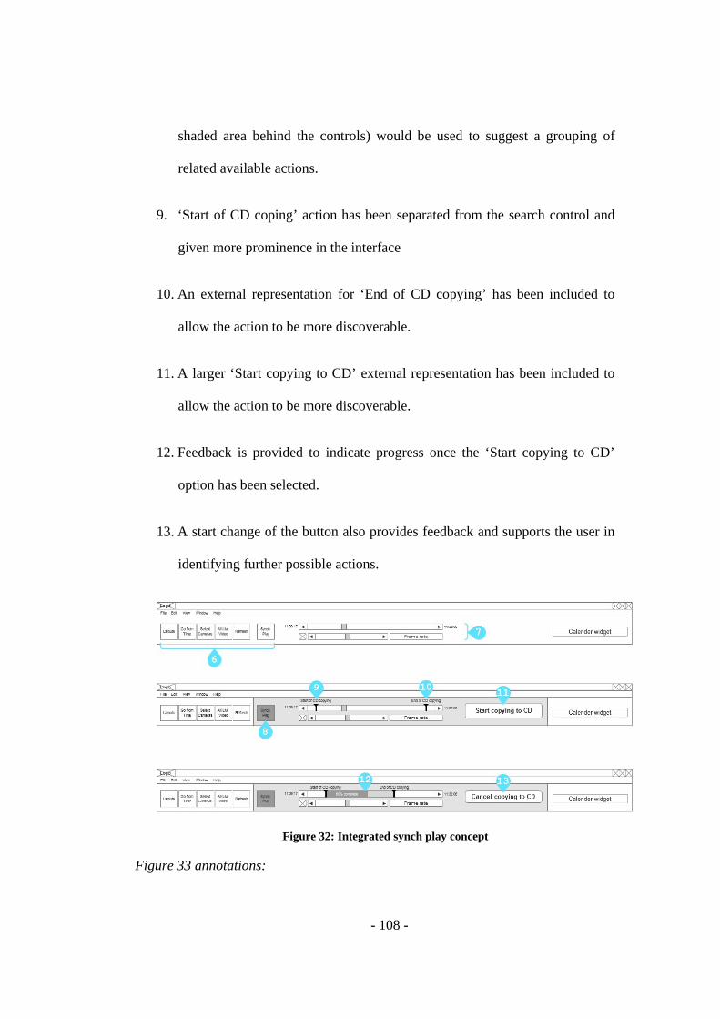
- 108 -
shaded area behind the controls) would be used to suggest a grouping of
related available actions.
9. ‘Start of CD coping’ action has been separated from the search control and
given more prominence in the interface
10. An external representation for ‘End of CD copying’ has been included to
allow the action to be more discoverable.
11. A larger ‘Start copying to CD’ external representation has been included to
allow the action to be more discoverable.
12. Feedback is provided to indicate progress once the ‘Start copying to CD’
option has been selected.
13. A start change of the button also provides feedback and supports the user in
identifying further possible actions.
Figure 32: Integrated synch play concept
Figure 33 annotations:
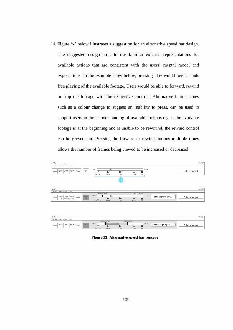
- 109 -
14. Figure ‘x’ below illustrates a suggestion for an alternative speed bar design.
The suggested design aims to use familiar external representations for
available actions that are consistent with the users’ mental model and
expectations. In the example show below, pressing play would begin hands
free playing of the available footage. Users would be able to forward, rewind
or stop the footage with the respective controls. Alternative button states
such as a colour change to suggest an inability to press, can be used to
support users in their understanding of available actions e.g. if the available
footage is at the beginning and is unable to be rewound, the rewind control
can be greyed out. Pressing the forward or rewind buttons multiple times
allows the number of frames being viewed to be increased or decreased.
Figure 33: Alternative speed bar concept

- 110 -
Figure 34: Alternative header concept
Figure 35: Alternative header concept - copy to CD selected

- 111 -
Figure 36: Alternative header concept - start copying to CD selected