extending wheelbase/moving axle 1
TRANSCRIPT

Chassis – Best PraCtiCes iPAG
E
Revised Date: 09/30/2017Chassis – Best Practices – 2018
Vehicle Body – Best Practices
EXTENDING WHEELBASE/MOVING AXLE ������������������������������������������������������������������������������������������������������������������������������������������������� 1Frame Extension ������������������������������������������������������������������������������������������������������������������������������������������������������������������������������������� 1
Alterations ��������������������������������������������������������������������������������������������������������������������������������������������������������������������������������������� 1 Frame ���������������������������������������������������������������������������������������������������������������������������������������������������������������������������������������������� 1
Altering the Wheelbase ��������������������������������������������������������������������������������������������������������������������������������������������������������������������������� 2 Frame Splice Location�������������������������������������������������������������������������������������������������������������������������������������������������������������������� 2 Frame Splice Preparation ��������������������������������������������������������������������������������������������������������������������������������������������������������������� 3 Frame Splice Procedure ����������������������������������������������������������������������������������������������������������������������������������������������������������������� 4
Extending the Frame (Rear Overhang) ��������������������������������������������������������������������������������������������������������������������������������������������������� 7 Holes ������������������������������������������������������������������������������������������������������������������������������������������������������������������������������������������������������� 8 Crossmembers ���������������������������������������������������������������������������������������������������������������������������������������������������������������������������������������� 9
Analyzing Frame Failure Causes ���������������������������������������������������������������������������������������������������������������������������������������������������������� 10 Collisions �������������������������������������������������������������������������������������������������������������������������������������������������������������������������������������� 10 Excessive Bending Moment ��������������������������������������������������������������������������������������������������������������������������������������������������������� 10 Localized Stress Concentration ��������������������������������������������������������������������������������������������������������������������������������������������������� 10 Attaching Reinforcements ������������������������������������������������������������������������������������������������������������������������������������������������������������ 11 Terminating Reinforcements ��������������������������������������������������������������������������������������������������������������������������������������������������������� 12
Welding ������������������������������������������������������������������������������������������������������������������������������������������������������������������������������������������������� 12Welding Equipment ���������������������������������������������������������������������������������������������������������������������������������������������������������������������� 13 Welding Methods �������������������������������������������������������������������������������������������������������������������������������������������������������������������������� 14 Dissimilar Metals��������������������������������������������������������������������������������������������������������������������������������������������������������������������������� 14
Driveshaft (Propshaft) Extension ���������������������������������������������������������������������������������������������������������������������������������������������������������� 16 Driveshaft Extension Design �������������������������������������������������������������������������������������������������������������������������������������������������������� 16 Two-Piece Driveshaft Bearings ���������������������������������������������������������������������������������������������������������������������������������������������������� 17Universal Joint Angles and Phasing ��������������������������������������������������������������������������������������������������������������������������������������������� 18 Multiple-Piece Driveshaft Alignment Procedure �������������������������������������������������������������������������������������������������������������������������� 19
Index

Chassis – Best PraCtiCes iiPAG
E
Revised Date: 09/30/2017Chassis – Best Practices – 2018
Vehicle Body – Best Practices
OCCUPANT BODY MOUNTING ����������������������������������������������������������������������������������������������������������������������������������������������������������������� 20General Requirements �������������������������������������������������������������������������������������������������������������������������������������������������������������������������� 20 Body Mounting Considerations ������������������������������������������������������������������������������������������������������������������������������������������������������������ 21 Body/Equipment Attachment Methods ������������������������������������������������������������������������������������������������������������������������������������������������ 21
Body Mounting Fasteners ������������������������������������������������������������������������������������������������������������������������������������������������������������ 22 Prevailing Torque Nuts (PTN)�������������������������������������������������������������������������������������������������������������������������������������������������������� 23
NTEA Recommended Body-Mounting Practices �������������������������������������������������������������������������������������������������������������������������������� 23 Type 1 – U-Bolt/Threaded Rod and End Plate ���������������������������������������������������������������������������������������������������������������������������� 23Type 2 – Brackets and Pinch Bolts ���������������������������������������������������������������������������������������������������������������������������������������������� 23Type 3 – Rigid Mounting (Service/Utility) ������������������������������������������������������������������������������������������������������������������������������������� 23Type 4 – Shear Plate Mounted ����������������������������������������������������������������������������������������������������������������������������������������������������� 23NTEA Body Classifications ����������������������������������������������������������������������������������������������������������������������������������������������������������� 24
Shear Plate Attachments ���������������������������������������������������������������������������������������������������������������������������������������������������������������������� 27
FUEL SYSTEMS ������������������������������������������������������������������������������������������������������������������������������������������������������������������������������������������� 28Fuel Fill �������������������������������������������������������������������������������������������������������������������������������������������������������������������������������������������������� 28Fuel Lines ���������������������������������������������������������������������������������������������������������������������������������������������������������������������������������������������� 29Fuel Tanks ��������������������������������������������������������������������������������������������������������������������������������������������������������������������������������������������� 30
Auxiliary Fuel Tanks ���������������������������������������������������������������������������������������������������������������������������������������������������������������������� 31Diesel Exhaust Fluid (DEF) System ������������������������������������������������������������������������������������������������������������������������������������������������������ 31
BRAKES�������������������������������������������������������������������������������������������������������������������������������������������������������������������������������������������������������� 32 General Requirements ���������������������������������������������������������������������������������������������������������������������������������������������������������������������������������� 32 Federal Standards and Regulations ������������������������������������������������������������������������������������������������������������������������������������������������������������� 32
Modification Checklist �������������������������������������������������������������������������������������������������������������������������������������������������������������������������� 32Brake Lines��������������������������������������������������������������������������������������������������������������������������������������������������������������������������������������������33
Parking Brake Systems ��������������������������������������������������������������������������������������������������������������������������������������������������������������������������������� 34 Electronic Dynamic Rear Proportioning (DRP) ��������������������������������������������������������������������������������������������������������������������������������������������� 35
Index (cont'd)

Chassis – Best PraCtiCes iiiPAG
E
Revised Date: 09/30/2017Chassis – Best Practices – 2018
Vehicle Body – Best PracticesIndex (cont'd)
EXHAUST SYSTEM ������������������������������������������������������������������������������������������������������������������������������������������������������������������������������������� 36 Exhaust System Design �������������������������������������������������������������������������������������������������������������������������������������������������������������������������������� 36 Routing �������������������������������������������������������������������������������������������������������������������������������������������������������������������������������������� 38 Shielding �������������������������������������������������������������������������������������������������������������������������������������������������������������������������������������� 38 Undercoating �������������������������������������������������������������������������������������������������������������������������������������������������������������������������������� 38
SUSPENSION SYSTEM ��������������������������������������������������������������������������������������������������������������������������������������������������������������������������������39 General Requirements ���������������������������������������������������������������������������������������������������������������������������������������������������������������������������39 Front Suspension �����������������������������������������������������������������������������������������������������������������������������������������������������������������������������������39 Rear Suspension ������������������������������������������������������������������������������������������������������������������������������������������������������������������������������������39
WHEELS AND TIRES �����������������������������������������������������������������������������������������������������������������������������������������������������������������������������������40
Chassis – Best PraCtiCes 1PAG
E
Revised Date: 09/30/2017Chassis – Best Practices – 2018
Vehicle Body – Best PracticesExtending Wheelbase/Moving Axle
Frame ExtensionThe frame extension is designed to maintain structural rigidity and performance while minimizing cost and part/assembly complexity. General Motors has conducted extensive engineering analysis of the frame with the objective of replicating base frame thickness for optimum dynamic performance. This analysis is the basis for recommendations on frame construction sections, section modules, metal thickness and specifications.
The frame extension must overlap the existing frame to ensure adequate strength in the tie-in areas. These areas are vehicle stress risers, subject to significant loads even during normal vehicle use. SVMs, therefore, should make every attempt to ensure consistent installation in the tie-in areas.
AlterationsWhen modifying the wheelbase, SVMs assume full responsibility for:
• compliance with applicable motor vehicle safety standards
• warranty on items such as driveshafts, universal joints, center bearings and rear transmission tailshaft, transfer case and transmission case fractures, output shaft bushings, bearings, brakes, fuel systems and any other
related component failures.
Additionally, the modifier’s owner manual must alert the customer that parts for the reworked area(s) are not available through the General Motors service parts system.
Frame
The SVM is responsible for any alterations to the frame assembly, including hole drilling, welding and modifications of any type. The SVM must also assume complete responsibility for reliability, performance and compliance to applicable FMVSS requirements.
This section outlines GM-recommended procedures and precautions for proper installation of special bodies and/or equipment on frames. Failure to follow these recommendations could result in serious damage to the basic vehicle.
Flanges
GM does not recommend drilling holes in frame flanges. Drilled holes in frame flanges will reduce fatigue life significantly. See Figure 10, page 9.
Holes When drilling holes for mount brackets, supports and outriggers in the frame rail vertical side wall, SVMs should observe the following recommendations:
• Material between the edge of the hole and inside of upper or lower flange must not be less than 37 mm (1.5 in.).
• The minimum edge distance between any two holes must be larger than twice the diameter of the larger hole.
• No hole should exceed 20 mm (0.75 in.) in diameter.

Chassis – Best PraCtiCes 2PAG
E
Revised Date: 09/30/2017Chassis – Best Practices – 2018
Vehicle Body – Best PracticesExtending Wheelbase/Moving Axle (cont'd)
Altering The Wheelbase –Frame Splice Location General Motors recommends splicing in a straight segment of the frame rail, just forward of the rear spring front hanger bracket (see Figure 1). This is the optimum location for maintaining frame strength and integrity. It also maintains minimum weld spacing from hanger bracket rivet, preventing hole/rivet shrinkage deformation. Other advantages to this location are: • Requires minimal exhaust, fuel, brake and electrical modifications. • Minimizes driveline modification issues from excessive angles and
misalignment.
Avoid altering chassis wiring. When shortening the wheelbase, simply secure a gentle bend or loose coil in the wiring.
Avoid cutting on uneven sections of the frame, such as frame forms or irregular bends and depressions.
General Motors highly recommends selecting a cut location approximately 203 mm (8 in.) forward of the rear spring front hanger bracket whenever possible. If using another location with the splice zone, SVMs should complete a stress analysis.
CAUTION
CAUTION
CAUTION
Figure 1
Chassis – Best PraCtiCes 3PAG
E
Revised Date: 09/30/2017Chassis – Best Practices – 2018
Vehicle Body – Best PracticesExtending Wheelbase/Moving Axle (cont'd)
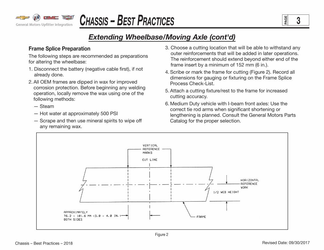
Frame Splice Preparation The following steps are recommended as preparations for altering the wheelbase:
1. Disconnect the battery (negative cable first), if not already done.
2. All OEM frames are dipped in wax for improved corrosion protection. Before beginning any welding operation, locally remove the wax using one of the following methods:
— Steam
— Hot water at approximately 500 PSI
— Scrape and then use mineral spirits to wipe off any remaining wax.
3. Choose a cutting location that will be able to withstand any outer reinforcements that will be added in later operations. The reinforcement should extend beyond either end of the frame insert by a minimum of 152 mm (6 in.).
4. Scribe or mark the frame for cutting (Figure 2). Record all dimensions for gauging or fixturing on the Frame Splice Process Check-List.
5. Attach a cutting fixture/rest to the frame for increased cutting accuracy.
6. Medium Duty vehicle with I-beam front axles: Use the correct tie rod arms when significant shortening or lengthening is planned. Consult the General Motors Parts Catalog for the proper selection.
Figure 2

Chassis – Best PraCtiCes 4PAG
E
Revised Date: 09/30/2017Chassis – Best Practices – 2018
Vehicle Body – Best PracticesExtending Wheelbase/Moving Axle (cont'd)
Frame Splice Procedure Use the following procedure for splicing the frame:
1. Locate a specific frame splice cut location, observing the location guidelines already outlined. Cut the frame within the frame splice zone.
2. Grind cut edges of the frame smooth for line-to-line fit. This ensures a good fit and clean metal surface for the welding operation.
Frame inserts must be the same dimensional shape, metal gauge/thickness, material type and yield strength as the original frame side member.
3. Chamfer the outside edge of both the frame and the insert at a 30-degree angle, leaving 1/2 of the thickness (Figure 3).
4. Relocate rear frame section of the vehicle to install frame insert when lengthening.
5. Fixture and clamp the insert to ensure correct alignment (Figure 4). Make dimensional checks against predetermined reference marks (as shown earlier in Figure 2) to prevent possible error.
Figure 3

Chassis – Best PraCtiCes 5PAG
E
Revised Date: 09/30/2017Chassis – Best Practices – 2018
Vehicle Body – Best PracticesExtending Wheelbase/Moving Axle (cont'd)
6. Tack weld runoff blocks to the edge of the upper and lower flanges of the frame and frame insert (Figures 5 and 6). This helps to eliminate joint edge burnout and prevent joint movement during butt welding.
7. Butt weld the outside edges of the frame insert to the frame. Grind visible welds on both sides to parent metal.
8. Butt weld the outside of the joint with a single pass — vertical up (Figure 5). Butt welds on the inside surface of the frame should also be done with a single pass (Figure 6).
Figure 5
Figure 6
Figure 4

Chassis – Best PraCtiCes 6PAG
E
Revised Date: 09/30/2017Chassis – Best Practices – 2018
Vehicle Body – Best PracticesExtending Wheelbase/Moving Axle (cont'd)
Figure 7
Variations in equipment and welding materials make it difficult to recommend specific amperage, electrode specifications and welding speed. Therefore, SVMs should have a qualified welder or consulting service establish and test this procedure. Standard industrial practices apply.
9. Visually inspect all welds for defects. This will ensure high-quality welds which are critical to joint integrity.
10. Remove runoff blocks and chip or grind the joint smooth. The out-side surface of the frame weldment must be as smooth as the rest of the frame to allow flush fit for reinforcement attachment. Make sure that grind marks are parallel to the length of the frame. The finished joint should be of the same thickness as the sidemember.
The outer reinforcement length is defined by the splice location and length of the insert, with a minimum 152 mm (6 in.) overlap on each end. The reinforcement must not encroach on the rear leaf spring front hanger bracket.
Avoid welding closer than 50.8 mm (2 in.) to this area. Doing so could shrink the spring bracket rivets, resulting in a loose joint.
Refer to Figures 7 and 8 for clarification throughout this section. The illustration in Figure 7 shows an acceptable reinforcement and weldment method. The method shown in Figure 8, however, is preferred because:
• The slots are smaller and can be more easily positioned to avoid clearance holes in the frame.
• Chamfered sides diminish stress concentrations in corners which can cause cracks to develop in the weld.
Use an L-shaped reinforcement made of the same material and thick-ness as the frame. Reinforcement height must allow for the weldment, but not exceed the tangent of the radius for the bend at the upper flange of the frame.
The inside radius of the reinforcement must be smaller than the outside radius of the frame so as to provide a gap at the bend.
11. Add holes to the reinforcement to provide clearance for all fasteners, rivets or retention clips in the frame sidemember.
Any frame identification number or VIN which would be lost when the wheelbase is stretched or shortened must be duplicated on the reinforcement or sidemember of the finished frame.
CAUTION

Chassis – Best PraCtiCes 7PAG
E
Revised Date: 09/30/2017Chassis – Best Practices – 2018
Vehicle Body – Best PracticesExtending Wheelbase/Moving Axle (cont'd)
Secure the L-shaped reinforcement with clamps to the outside of the frame rail. There should be no visible gaps between the frame rail and the reinforcement other than at the bend. Fillet weld the reinforcement to the frame rail, using a skip weld technique. That is, a 50.8 mm (2 in.) weld followed by an equal space continuously along the span of the reinforcement.
Leave corners, bends and radii free to flex. Welding in these locations creates stress risers that can often lead to cracks in the weld.
Do not weld at the lower flange of the frame, either on the flange or at the edge.
For the final weld operation, fillet weld the reinforcement slots or holes to the frame. It is acceptable, but not necessary, to fillet weld the entire circumference of the slots or holes. Adding a fillet weld on the bottom half (180 degrees) only will provide sufficient strength.
After final welding, reapply undercoating to the exposed portion of the frame unless the area to be covered is closer than 305 mm (12 in.) from any exhaust component. For components falling within this area, use paint rather than undercoating to provide corrosion protection.
Extending The Frame (Rear Overhang)When lengthening rear frame extensions, SVMs must exercise great caution to avoid adversely affecting vehicle performance in the following areas:
• Excessive rear extensions allow customer opportunity to significantly unload the front end of the vehicle. This can result in customer dissatisfaction with vehicle braking and/or steering and handling.
• Rear frame extensions must be long enough to protect vulnerable components, such as fuel tanks, and short enough to avoid a negative effect on approach, departure and brake-over angles.
For guidelines on frame wax (corrosion protection) removal, refer to “Altering the Wheelbase” on page 3 in this section.
Figure 8

Chassis – Best PraCtiCes 8PAG
E
Revised Date: 09/30/2017Chassis – Best Practices – 2018
Vehicle Body – Best PracticesExtending Wheelbase/Moving Axle (cont'd)
HolesIt is important to locate holes in the least critical area possible. In high-load areas, place holes near the neutral axis of the side rail or horizontal center line of the web.
The illustration in Figure 9 was taken from a laboratory test conducted to study stress at a hole under beam loading. In this test, the section was covered with photo stress plastic which shows stress through color fringes when viewed under polarized light.
The illustration shows a channel-section siderail loaded vertically as a beam. This type of loading stretches the lower half of the section and compresses the top half as indicated by the arrows. There are two holes in the lower half, the uppermost of which is located about one-third of the rail depth up from the bottom flange. Stress at the bottom of this hole is approximately equal to the stress in the flange. Any hole located less than this distance from the bottom flange will have significantly higher stress than the flange. Figure 10 illustrates these principles more specifically.
Figure 9

Chassis – Best PraCtiCes 9PAG
E
Revised Date: 09/30/2017Chassis – Best Practices – 2018
Vehicle Body – Best PracticesExtending Wheelbase/Moving Axle (cont'd)
Figure 10
To avoid premature failure, SVMs should observe these general guidelines: • Use existing holes wherever possible.
• Locate holes no closer to the top or bottom flange than existing holes placed by the chassis manufacturer.
• Avoid placing holes in the lower one-third of the web in the area immediately behind the cab.
CrossmembersAdditional frame crossmembers are required whenever a two-or three-piece driveshaft is used to support the center bearing and shaft. Crossmember design should meet the following criteria:
• Adequate vertical stiffness to prevent resonance with prop shaft imbalance excitation in the vehicle speed range.
• Adequate strength to support the weight of the prop shaft and support bearing, with respect to maximum vertical acceleration of the prop shaft. (Note: Crossmember has adequate strength if stiffness requirement is met.)
• Crossmembers should be rigidly welded, bolted or riveted to the frame rails.
• Designed to avoid retention and other foreign matter.
• Should not protrude excessively below the underbody and frame rails to prevent reduction in ramp break-over and ground clearances.

Chassis – Best PraCtiCes 10PAG
E
Revised Date: 09/30/2017Chassis – Best Practices – 2018
Vehicle Body – Best PracticesExtending Wheelbase/Moving Axle (cont'd)
Analyzing Frame Failure CausesIn some cases, such as a vehicle collision, the reason for frame failure is easily apparent. In others, however, determining the cause is considerably more difficult. Frame failures can generally be traced to one of three reasons:
• Vehicle collision
• Excessive bending moment
• Localized stress concentration
CollisionsFailures caused by collisions should be repaired using proper methods and reinforcements as necessary.
Excessive Bending MomentOverload, improper weight distribution or vehicle misapplication can cause excessive bending moment failures. This type of failure occurs at different areas on different types of vehicles.
Localized Stress ConcentrationLocalized stress concentration failures may result from bending moment stresses. However, stress levels would not be high enough to cause any difficulty without localized stress concentration points. Localized stress concentration points maybe caused by:
• poor body or fifth wheel mountings
• special equipment or accessory installation
• improper welding or welding methods
• improper reinforcements
• loose bolts or rivets
• defective material
They may also result from high bending loads, coupled with severe torsional loads (e.g., off-road applications).
Fifth Wheel InstallationGeneral Motors recommends attaching fifth wheel or body mounting to the frame rail web section, not through flanges. Refer to the GM Body Builders Manual for proper installation procedures.
Using U-bolts to attach fifth wheels or bodies is not an approved installation method. Doing so may result in the development of high-stress concentration.
Special Equipment/Accessory Installation
Installing special equipment or accessories can cause high-stress concentrations due to the attachment method or their added weight.
• Never drill holes through flanges.
• Avoid drastic changes to section modulus. Section modulus changes usually occur when large mounting plates are added to support special equipment.
• Avoid mounting heavy equipment across the flanges or on side-rail webs. Doing so may result in stress concentration high enough to cause failure of the nearest crossmember, bracket or other frame stiffener or through a nearby hole in the frame flange.

Chassis – Best PraCtiCes 11PAG
E
Revised Date: 09/30/2017Chassis – Best Practices – 2018
Vehicle Body – Best PracticesExtending Wheelbase/Moving Axle (cont'd)
Improper welding or welding methods are a major cause of stress concentration points, which may ultimately result inframe failure. Refer to general welding instructions outlined under “Welding” on page 13 in this section.
ReinforcementsUsing improper reinforcements or attachment methods may create localized stress concentrations. This may actually reduce the frame load-carrying capacity to below that of the original frame (i.e., before adding reinforcements). There are five basic types of reinforcement (see Figure 11). Their descriptions follow.
Figure 11
Upright “L” reinforcements should be used in maximum stress locations, at the bottom of the lower flange and where buckling of the upper flange is not a problem. They may be placed either inside or outside the frame side rail. The upright “L” reinforcement is quite versatile and may be used as full-length or short localized reinforcement. However, it may be limited by the configuration of the frame or spring hanger brackets.
Inverted “L” reinforcements also may be used inside or outside of the frame rail. They are recommended where maximum stress is transferred to the upper flange, for example dump trucks with the box in the raised position. This type of reinforcement is easily adapted to frame and hangerbracket designs which prohibit using an upright “L” reinforce-ment or where the upper flange is subject to buckling.
Channel reinforcements can be used for full-length or localized reinforcement and can be installed inside or outside the frame side rail. Two major disadvantages are their added weight and required installation time. It may also be difficult to place the channel inside or over the existing rail due to manufacturing tolerances, crossmembers or mounting brackets.
Chassis – Best PraCtiCes 12PAG
E
Revised Date: 09/30/2017Chassis – Best Practices – 2018
Vehicle Body – Best PracticesExtending Wheelbase/Moving Axle (cont'd)
Terminating ReinforcementsTo prevent localized stress concentration, reinforcements must be properly terminated. Reinforcement ends must be tapered or stress relieved. Tapers should not exceed 45 degrees.
When using several reinforcements together, stagger them so that their ends overlap by 203-255 mm (8-10 in.).
Frame Repair and Reinforcement: General RulesSpecific frame repair and reinforcement procedures vary depending on circumstances and materials. The general guidelines outlined here, however, are very important and apply to virtually all repair and reinforcement situations.
• Always identify the material that makes up the base rail. Reinforcement should be of the same or better material than the base rail.
• Make sure that only fully trained, qualified specialists perform frame straightening and other repairs.
• Always try to identify the cause of the failure.
• Do not attach fifth wheels or body and accessory mountings through frame flanges. Refer to GM Body Builders Manual for additional information.
• Do not drill holes in top or lower flanges.
• Use only proper electrodes as specified for base rail material when welding is necessary.
• Do not use oxyacetylene welding equipment on frames.
• Do not weld reinforcements across the frame flanges.
• Do not weld within 19 mm (0.75 in.) of the edge of a frame flange.
• Remove all notches or weld buildups from flange edge when repairing a broken frame.
• Do not weld cast brackets to frame.
• Do not weld flanges of cracked reinforcements and base rails together.
• Do not patch cracks. Make correct repair and reinforce the area.
• Always scarf reinforcement ends to provide adequate stress relief.
• Always stagger ends of reinforcements by a minimum of 203 mm (8 in.) apart.
• Before welding, disconnect negative battery cable to prevent possible electrical damage to generating system.
WeldingWelding is an excellent attachment or repairmethod. SVMs, however, must be very careful touse proper welding procedures. Inferior welds andimproper methods can cause further frame damageand additional reinforcements may be requiredlater to prevent the problem from reccurring. Referto the specifications table in Figure 13 for properwelding electrode identification and usage.
Prior to any welding, disconnect all negative (ground) cable(s) from all battery(ies).
WARNING

Chassis – Best PraCtiCes 13PAG
E
Revised Date: 09/30/2017Chassis – Best Practices – 2018
Vehicle Body – Best PracticesExtending Wheelbase/Moving Axle (cont'd)
Welding Equipment
Never use oxyacetylene to weld frame rails.
CAUTION
Electric arc-welding is recommended for steel frame modifications. Shielded Arc Method is recommended because heat generated during welding is localized with minimal burning of material. In addition finished weld can be ground flush and drilled if necessary. Shielded metal arc welding (SMAW); gas metal arc welding (GMAW), also know as metal inert gas (MIG) welding; gas tungsten arc welding (GTAW), also know as tungsten inert gas (TIG) welding; or flux cored arc welding (FCAW) all recommended methods.
NOTE: Weld procedure recommendations: • Welding can be performed only when surfaces are clean and dry. • Surface areas and edges to be joined must be clean and free of oil, grease, loose scale, rust, moisture, paint or other material.• Preheat areas to be welded to avoid craters, notching and undercutting. • Peen new welds prior to grinding to relieve stresses.• Grind all weld flush with the surrounding surfaces• Inspect the weld area carefully after grinding. Grind out any remaining notches or undercuts.
• For welds extending to the edge of the flange, locate a run-off block at the edge to obtain a continuous weld without undercuts. After welding, the run-off block should be cut off.• Electrodes: Only low hydrogen electrodes should be used; use proper care for exposure and storage.• Seal weld with rust preventative coating. NOTE: Welding procedures vary with different frame materials. Issues resulting from weld modifications to chassis / frame may not be covered by warranty. Altering the wheelbase of a vehicle may affect frame resonant frequencies. Frame stiffening may be necessary to avoid undesirable frame flex.
Identification of Frame Rail MaterialChassis are manufactured with frame rails of alloy steels, including heat-treated reinforced versions. Frame material must be identified before attempting frame modification.Chassis are manufactured with frame rails of: • High strength low alloy steel (HSLA) 40,000 Mid-Size Truck, 33,000-60,000 LD/HD Truck and 60,000-80,000 Med-Duty Truck; PSI yield strength.• Heat-treated steel (HT) 100,000- 120,000; PSI yield strength.

Chassis – Best PraCtiCes 14PAG
E
Revised Date: 09/30/2017Chassis – Best Practices – 2018
Vehicle Body – Best Practices
Welding MethodsFour basic welding types (Figure 12) are used to repair and reinforce frame rails. These methods can be used with any type of material.
Figure 12
Extending Wheelbase/Moving Axle (cont'd)
• Continuous Fillet (Longitudinal Butt) Weld — This is used to weld a continuous bead along a reinforcement on the frame rail web section, or to add gussets or plates to crossmembers. Continuous fillet welds should never be made across frame flanges or along their inside edges. When welding in a flat position, use high range of electrode current. For welding overhead or in difficult areas, use low range of electrode current. Use the voltage specified for the electrode.
• Groove Welding — This basic repair weld is also called transverse butt ground welding. It is applied after grounding the surface for good penetration. When welding cracks, make sure to cross either the upper or lower flanges. Weld completely and then grind off excess weld to remove notches or weld buildup on the flange edge. Use medium range of electrode current.
• Plug Welding — Plug (or ring) welds are good for attaching reinforcements because they eliminate the possibility of loose-fitting bolts. Be careful, however, to properly place plug welds in different types of reinforcements. GM highly recommends E-7018 electrode for plug welding because of its good pene- tration and light coating. Use high range of electrode current and appropriate voltage for flat or vertical plug welds. Overhead plug welding is very difficult. Do not use this method unless other approaches are impractical. Then use high range for first pass and complete plug at medium range. Refer to plug weld table (Figure 13) for hole size to use for material thickness variations.
• Stitch (Intermittent Fillet) Welding — This type is also called transverse or longitudinal fillet. It is not generally used on frames because continuous fillet welding provides better attachment. Stitch weld when warp and heat control is critical, using medium range of electrode chart.
For all types of welding, make sure to:
• Connect welding machine ground cables as close to work area as possible.
• Use smaller diameter electrode whenever possible, and make several passes rather than large diameter and single passes.
Vehicle load capacity depends on strength and rigidity. For effective repairs, make sure that frame service is performed only by qualified personnel using proper materials and equipment.
Dissimilar MetalsTo prevent a chemical reaction, apply a barrier coating of good corrosion-inhibiting compound to all faying surfaces of dissimilar metals. Remove old sealer with a putty knife.
Before stripping the vehicle down for repair, make sure to support the frame on a smooth, level floor. This will permit frequent checking for alignment during the straightening and replacement process.

Chassis – Best PraCtiCes 15PAG
E
Revised Date: 09/30/2017Chassis – Best Practices – 2018
Vehicle Body – Best PracticesExtending Wheelbase/Moving Axle (cont'd)
High Strength Low Alloy Steel Frame Weld Recommendations (40,000 - 80,000 PSI Yield Strength)Any of the electric arc methods previously described may be used (see Page 14). The choice of an electrode or wire depends somewhat upon welding equipment available and method selected.
The SMAW and GMAW methods (see below) are preferred for welding HSLA frames. Use of low hydrogen electrodes is recommended. Refer to Tables 1 and 2 for selection of recommended electrodes and wires and refer to A.W.S., A.5 standards from: American Welders Society, 2501 N.W. 7th Street, Miami, FL 33125 (www.aws.org).
Table 1: SMAW Method (HSLA Frames)
Position Electrode Sizes Inch Amperes Volts Speed (inch/Min.) Flat 0.125 — — — Horiz & Vert 0.125 110/140 20/14 24
Table 2: GMAW Method (HSLA Frames)
Position Electrode Sizes Inch Amperes Volts Speed (inch/Min.) Flat 0.035 — — 350/400 Horiz & Vert 0.035 190/220 20/30 350/400
Table 3: SMAW Method (HT Frames)
Position Electrode Sizes Inch Amperes Volts Speed (inch/Min.) Horiz & Vert 0.093 21/24 2.0 75-115 Horiz & Vert 0.125 21/24 2.5 90-160 Horiz & Vert 0.156 21/24 3.9 130-220 Horiz & Vert 0.187 21/24 5.1 200-300 Horiz & Vert 0.250 21/24 7.8 300-400
Heat Treated Frames Weld Recommendations (100,000 - 120,000 PSI Yield Strength)Note: When welding 100,000 - 120,000 PSI yield strength Heat Treated Frames use SMAW method with low hydrogen electrodes (refer to table 3) that meets or exceeds AWS-E-11018.
Chassis – Best PraCtiCes 16PAG
E
Revised Date: 09/30/2017Chassis – Best Practices – 2018
Vehicle Body – Best PracticesExtending Wheelbase/Moving Axle (cont'd)
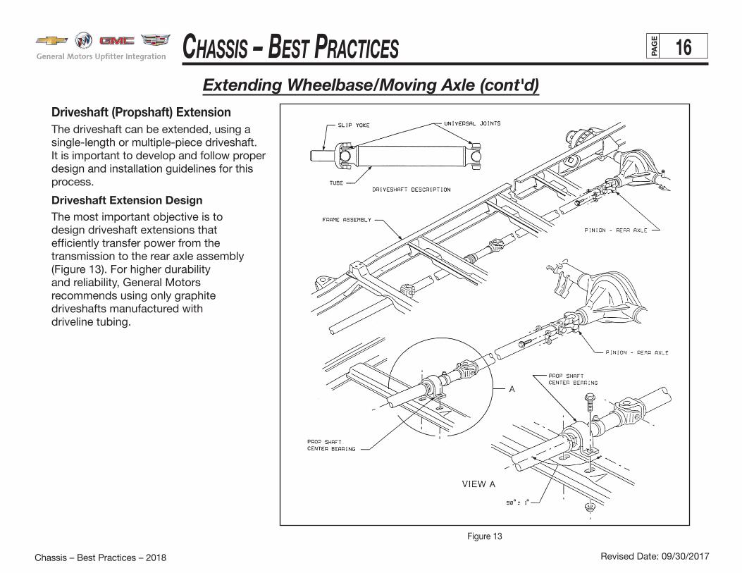
Driveshaft (Propshaft) ExtensionThe driveshaft can be extended, using a single-length or multiple-piece driveshaft. It is important to develop and follow proper design and installation guidelines for this process.
Driveshaft Extension DesignThe most important objective is to design driveshaft extensions that efficiently transfer power from the transmission to the rear axle assembly (Figure 13). For higher durabilityand reliability, General Motors recommends using only graphite driveshafts manufactured with driveline tubing.
Figure 13

Chassis – Best PraCtiCes 17PAG
E
Revised Date: 09/30/2017Chassis – Best Practices – 2018
Vehicle Body – Best PracticesExtending Wheelbase/Moving Axle (cont'd)
Two-Piece Driveshaft BearingsFor two- or three-piece driveshaft applications, use an in-line bearing assembly. Figure 14 shows a typical two-piece driveshaft.
Recommended bearing locations vary with vehicle stretch length. If the driveshaft exceeds 1,524 mm (60 in.), use a two-piece assembly with an in-line bearing assembly. Keep the driveshaft lengths asclose to equal as possible.
Figure 14
Figure 15
• SVMs should devise a gauge by which to measure driveshaft alignment angles for front and rear shafts. For smooth operation, the front must align with the rear shaft in both side and plan views (Figure 15). Check for this vertically and along the horizontal center
line (Figure 16).

Chassis – Best PraCtiCes 18PAG
E
Revised Date: 09/30/2017Chassis – Best Practices – 2018
Vehicle Body – Best Practices
Figure 16
Extending Wheelbase/Moving Axle (cont'd)
• For maximum support, mount bearing assembly to a cross-member. Final driveshaft alignment must allow vertical and horizontal bearing adjustment.
• Make sure to protect the in-line bearing from common operating conditions such as weather and road debris. General Motors recommends mounting a protective bridge between the bearing assembly and the ground. Fasten the bridge with bolts to facilitate serviceability.
• Splicing driveshaft tubes is not recommended. Splice welds create irregularities on inner and outer surfaces, making it difficult to
balance the driveshaft. Additionally, splice welding may cause embrittlement, increasing the possibility of driveshaft failure.
• Protect the driveshaft and universal joints from common operating conditions (e.g., potholes), by mounting heavy-duty frame cross-members between the driveshaft and the road surface.
• The driveshaft should be dynamically balanced at 25/65 mph (40-105km).
Use only General Motors or equivalent parts for driveshaft installation and service.
For additional information, refer to SAE J901 (Universal Joint and Driveshafts — Terminology — Application).
Universal Joint Angles and PhasingWhen an ordinary universal joint is operated at an angle, the driven yoke fluctuates slightly in speed as the joint rotates. That is, although the driving yoke rotates at a constant speed, the driven yoke speeds up and slows down twice per revolution. This fluctuation of the driven yoke is in direct proportion to the angle through which the universal joint is operating. The greater the angle, the greater the fluctuation.
This fluctuation and resulting vibration can be eliminated by phasing the universal joints at each end of the shaft so that the alternate acceleration and deceleration of one joint is offset by equal and opposite accelerations of the other joint. Correct phasing is achieved by aligning the universal jointlugs on each end of the shaft (refer back to Figure 15).

Chassis – Best PraCtiCes 19PAG
E
Revised Date: 09/30/2017Chassis – Best Practices – 2018
Vehicle Body – Best Practices
Universal Joint Angles and Phasing (cont'd)To allow the propshaft to operate as smoothly as possible, make sure that the input universal joint is approximately equal and opposite to the output universal joint angle. That is, the downward angle (a) of the transmission output shaft, relative to the driveshaft axis must be equal to the downward angle (b) of the pinion as shown in Figure 16. (Note: Angles shown are exaggerated for clarity.) To allow the best compromise for the pinion angle as it changes because of vehicle loading, acceleration and ride motion, these angles are determinedand set at the factory. This eliminates the need for adjustment by the SVM.
Universal joints are designed to operate safely and efficiently within a 3-degree joint angle. Exceeding this design limit may break the joint or cause excessive driveline vibration.
Extending Wheelbase/Moving Axle (cont'd)
Figure 17
Multiple-Piece Driveshaft Alignment ProcedureThe bearing supporting the driveshaft must be positioned vertically and laterally so that driveshaft segments are all in a straight line between the transmission output yoke and differential input flange. The following recommended procedure should enable SVMs to properly align the driveshaft, regardless of build variation.
1. After extending the vehicle, install the driveshaft bearing support crossmember (without the driveshaft or support bearing).2. Position the vehicle on a drive-on hoist or otherwise allow it to rest fully on the tires, so that the rear suspension is at curb height.3. Attach one end of a string from the center of the transmission spline as indicated to the center of the pinion attachment flange. Pull string taut.4. Measure the vertical distance from the center of the bearing mounting area of the crossmember to the string (dimension H, Figure 17).5. With a square just contacting the string in the lateral directions, mark the crossmember to indicate the correct lateral position of the center of the bearing.6. Add shims under the bearing so that the center height of the bearing is equal to the measurement taken in step 5. Mark the base of the bearing to indicate its lateral center.7. Remove string. Install bearing and driveshaft with shims under the bearing so that its center aligns laterally with the mark on the crossmember. The bearing center should be at the same point as the string. For vehicles requiring more than one bearing support, perform this procedure for each bearing.
For vehicles requiring more than one bearing support, perform this procedure for each bearing.

Chassis – Best PraCtiCes 20PAG
E
Revised Date: 09/30/2017Chassis – Best Practices – 2018
Vehicle Body – Best PracticesOccupant Body Mounting
Figure 18
Optimum body-mount location varies by frame wheelbase length. The best locations, for effective isolation from road vibration, are those closest to frame crossmembers and underbody crossbars. For optimum load-distribution isolation, additional body mounts should be no farther apart than762 mm (30 in.). When designing and locating body mounts, SVMs should also consider serviceability and the recom-mendations outlined in the “General Requirements” section that follows.
General RequirementsTo maintain base vehicle performance, it may be necessary to add, change or move body mounts along the frame. General Motors recommends the following practices for SVM-added body mounts:• Use only GM or equivalent body mounts. Use OEM rubber
body isolators, frame/body rails and/or outrigger brackets on the frame vertical side web.
• Avoid mounting bodies directly to the top of the frame. Doing so restricts frame torsional flexibility. It may also promote body cracking and provide a direct path for chassis noise, vibration and harshness (NVH). Figure 18 shows typical body mounts.
• Never weld body supports directly to the frame flanges. Do not weld body structures directly to frame extensions behind the rear suspension. Use consistent body attachment methods along the entire frame length.
• Use reinforcements or filler blocks where mounting devices may deform frame flanges. Mounting devices must be locked units that minimize loosening, but can be retightened if necessary. Use grade 8 PTN nuts.
• Correctly position all body mounts directly under cargo body crossmembers or longitudinal members to prevent body fatigue failures.
• Ambulance and other sensitive-cargo bodies require reduced stress on the body and frame. To accomplish this, minimize height above the frame and isolate the compartment from noise and vibration. Use full-floating, automotive style rubber body mounts or other chassis manufacturer-approved body mount systems. For bodies up to 3708 mm (146 in.) in length, install a minimum of four per side; for longer bodies, at least five per side.
Chassis – Best PraCtiCes 21PAG
E
Revised Date: 09/30/2017Chassis – Best Practices – 2018
Vehicle Body – Best Practices
UPFIT BODY SILL
HARDWOOD SPACER
CHASSIS RAIL
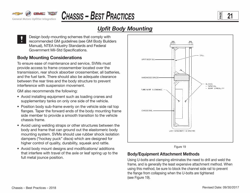
Upfit Body Mounting Design body-mounting schemes that comply with
recommended GM guidelines (see GM Body Builders Manual), NTEA Industry Standards and Federal Government Mil-Std Specifications.
Body Mounting ConsiderationsTo ensure ease of maintenance and service, SVMs must provide access to frame crossmember located over the transmission, rear shock absorber crossmember, all batteries, and the fuel tank. There should also be adequate clearance between the rear tires and the body structure to prevent interference with suspension movement.
GM also recommends the following:
• Avoid installing equipment such as loading cranes and supplementary tanks on only one side of the vehicle.
• Position body sub-frame evenly on the vehicle side rail top flanges. Taper the forward ends of the body mounting frame side member to provide a smooth transition to the vehicle chassis frame.
• Avoid using welding straps or other structures between the body and frame that can ground out the elastomeric body mounting system. SVMs should use rubber shock isolation dampers (“hockey puck” discs) which are designed for higher control of quality, durability, squeak and rattle.
• Avoid body mount designs and modifications/ additions that interfere with travel of the axle or leaf spring up to the full metal jounce position.
Figure 19
Body/Equipment Attachment MethodsUsing U-bolts and clamping eliminates the need to drill and weld the frame, and is generally the least expensive attachment method. When using this method, be sure to block the channel side rail to prevent the flange from collapsing when the U-bolts are tightened(see Figure 19).

Chassis – Best PraCtiCes 22PAG
E
Revised Date: 09/30/2017Chassis – Best Practices – 2018
Vehicle Body – Best PracticesUpfit Body Mounting (cont'd)
Common Upfit Body To Frame Mounting Figure 20 Upfit Body Frame ZW9 Attachment Provisions Figure 21
Use spacers between the subframe and the chassis frame as shown in Figure 20. Make sure that spacers do not interfere with plumbing or wiring routed along the frame rail and do not weld them to the frame flanges. Metal spacers are preferred as wood can shrink and drop out.
Clamping devices offer potential savings in both cost and installation time. Some equipment manufacturers have already incorporated clamped attachments into their designs because of these benefits. Since U-bolts and clamping devices depend on friction and a maintained clampingforce for attachment, a positive bolted connection should also be used for security.
Bolted attachments are generally preferred over welding because they retain more strength and are more easily serviced.
Body MountingSVMs should observe the following recommendations for bodymounting:• U-Bolts(Type1&2) are commonly used for securing upfit bodys, should not be used on down turned flanged frames nor in sloped sections. No notching frames for U-Bolts, use steel or hardwood anti-crush spacers to protect flanges.• Mechanical attachment(Type 3), use Grade 8 Bolts/Nuts for upfit body Mechanical attachments. Use available frame attachment provisions. (see Figure 21)• Shear Plates(Type 4) should be located at front & rear(aft of rear spring hanger) of upfit body span on chassis.• Use hardwood anti-crush spacers & elastomeric rubber to meet upfit body to frame damping requirements.• No upfit body to frame attachment welding in high stress areas. Welding allowed aft of rear spring shackles only.• Provide upfitter specific maintenance communication for mechanically fastened upfit body attachments requiring periodic inspection.

Chassis – Best PraCtiCes 23PAG
E
Revised Date: 09/30/2017Chassis – Best Practices – 2018
Vehicle Body – Best PracticesUpfit Body Mounting (cont'd)
Prevailing Torque Nuts (PTN)Prevailing torque nuts (PTN) have an interference fit on the threads. The interference fit prevents the nut from loosening after it is tightened, eliminating the need for cotter pins or lock washers. PTN fasteners are recommended for several body-mounting applications.
NTEA Recommended Body-Mounting PracticesThe National Truck Equipment Association (NTEA) advises that proper body mounting practices and materials are necessary in order to avoid damaging the frame side rail and body. This can occur when load and chassis movement cause uneven distribution of stress and strain.Attention to proper mounting and specifications is also critical to maintaining vehicle ride and handling characteristics.The NTEA Body Practices Subcommittee has reviewed the mounting methods of several chassis manufacturers and has identified four general types.Type 1 — U-Bolt mounting method uses U-bolt/threaded rod and end plate to secure the body’s longitudinal mounting rails to the chassis frame. Fillers or strips of hardwood or hard rubber act as cushions between the longitudinal mounting rails and the chassis frame. Secure the filler to frame or rail with steel banding or equivalent. The hardwood filler should taper approximately 1 inch per foot, starting at the front end and extending about 300 mm (11.8 in.) (Figure 19 & 20) back. The first tie-down should be positioned no more forwardthan the rear edge of the taper. For longitudinal body control, secure the shear plates with grade 8 bolts or weld them to the longitudinal mounting rails. Prevailing torque nuts are preferred in all threaded connections over double nuts. Spacers (prefer-ably metal) placed between the flanges of both the longitudinal mounting rail and the frame at each tie-down will prevent the
flanges from collapsing. Two guide plates (see Figure 27), one on each side at the front, will prevent lateral shifting of the body.This type of mounting is generally suitable for non- or semi-rigid bodies.Type 2 — Brackets and Pinch Bolts in this method are fabricated and/or formed brackets of angles welded and/or bolted to the longitudinal mounting rails and chassis frame. A bolt pinches the brackets together to secure them. A filler, cushion or strip (preferably of hard rubber) may be used between the longitudinal mounting rails and the chassis frame. If so, it should be secured to prevent loss or movement.
SVMs should specify the zone or area between the back of the cab and rear axle(s) where spring mounts should be used. Shear plates should be bolted or welded to the body longitudinal mounting rails and bolted to the chassis web, but not in top flanges. (Note: Use grade 8 fasteners to secure the shear plates.)Prevailing torque nuts are preferred in all threaded connections (instead of double nuts).Type 3 — Rigid Mounting & Semi-Rigid This category includes industry practice of mechanical attachment to frame flanges using already existing holes including pickup box attachment points. Intended for vehicles under 15,000 pounds GVWR with service/utility bodies.Type 4 — Shear Plate Mounted This mounting type is used to attach non-rigid subframes to OEM frames (Figure 22 & 25). Non-rigid body types include platform, stakebed, dump, rollback carriers and open-top grain/livestock bodies. Multiple fasteners should be used at frame attachment.

Chassis – Best PraCtiCes 24PAG
E
Revised Date: 09/30/2017Chassis – Best Practices – 2018
Vehicle Body – Best PracticesUpfit Body Mounting (cont'd)
Figure 22
Rear Frame Attachment
NTEA Body ClassificationsThe NTEA Body Practices Subcommittee defines vehicle body types in terms of torsional rigidity, grouping them into four basic categories:• Non-rigid • Semi-rigid• Rigid • Super rigidThe degree of rigidity determines the appropriate attachment method. The table below lists the torsional rigidity of selected body types.
Torsionally Flexible BodiesBodies with wood or metal sill construction are considered torsionally flexible. When mounting torsionally flexible bodies, consider the following points:• The sill should rest directly and squarely on frame side rails.
Wood sills must be chamfered 13 mm (0.5 in.) at the front end, tapering to meet the frame approximately 300 mm (11.8 in.) from front end of sill (see Figure 27).
• Sills must not overhang outside of frame. If wood sill is not as wide as frame flange, install spacer blocks at hold-down. Wood grain of blocks should be parallel (up and down) with hold-down.
Torsional Rigidity Of Selected Body Types
Body Mounting Non-Rigid Semi-Rigid Rigid Super Rigid
Service
High/with Top •
Low/without Top •
Platform •
Dry Freight Van Body
Rollup Door •
Swing Door •
Dump Bodies •
Wreckers •
Rollback Carriers •

Chassis – Best PraCtiCes 25PAG
E
Revised Date: 09/30/2017Chassis – Best Practices – 2018
Vehicle Body – Best Practices
Figure 25 Figure 26Combination U-Bolt, Shear Plate & Spring-loaded Forward Mount (ZW9)
Body Mounting (cont'd)• Mountings must be spaced to clear suspension and any
other parts attached to frame side rail. Use U-bolts 13 mm (0.5 in.) minimum diameter for each mounting. One mounting should be located at the front end of sill (at or as close to rear end of taper as possible), one near the
rear end and others should be spaced as nearly equally as possible between front and rear mountings. Do not mutilate the frame side rails in any way to accommodate mountings.

Chassis – Best PraCtiCes 26PAG
E
Revised Date: 09/30/2017Chassis – Best Practices – 2018
Vehicle Body – Best PracticesUpfit Body Mounting (cont'd)
Upfit Body Frame Attachment Cutaway Van Chassis Figure 23 Cutaway Van Body Trunnion Mount Figure 24
Torsionally Rigid BodiesBecause of their solid construction, torsionally rigid bodies require a more flexible mounting. Trunnion and spring-loaded body mountings provide optimum frame and body life.

Chassis – Best PraCtiCes 27PAG
E
Revised Date: 09/30/2017Chassis – Best Practices – 2018
Vehicle Body – Best Practices
When mounting a body of this type, SVMs should follow these guidelines:• Use a hardwood spacer, with a minimum thickness of
19 mm (0.75 in.) between the body sill and frame side rail. Make sure the spacer is chamfered 13 mm (0.5 in.) at the front end and tapered to meet the frame approximately 300 mm (11.8 in.) from the front end of the spacer.
• Use a body guide (Figure 27), to restrict lateral movement of the body and relieve shear stress on mountains. Bolt or weld the body guide to the body sill near front end of the body. It should extend below the body sill and contact the wear plate bolted to the frame side rail.
• Use spring-loaded, angle-type mountings (Figures 26 & 27). They may be bolted or welded to the body sill. However, always use bolts to attach them to the frame side rail. Do not weld directly on the frame side rail. Position mountings to allow a clearance of at least 6 mm (0.25 in.) between upper and lower brackets. Use SAE Grade 8 or Class 10.9 metric bolts with PTN nuts. Spring-loaded mounting bolts also require PTN nuts. The springs should be as short as practical, allowing preloading which will help prevent excessive “body roll” during operation, and a minimum of 25 mm (1 in.) at the front of the body before becoming solid.
• Trunnion-type body mountings also provide flexibility and are acceptable substitutes for the spring-loaded type. (Figures 23 & 24)• Locate bolts (13 mm/0.5 in. minimum diameter) near the rear
of the body sills. Before final attachment, make sure to allow clearance of at least 1.5 mm (.06 in.) between upper and lower shear plates.
Upfit Body Mounting (cont'd)
Upfit Body Guide Plate and Spring Mount Figure 27
Shear Plate AttachmentsWhenever possible, use existing holes to attach shear plates to the frame side rails. When additional holes are required, make sure they are no larger than 20 mm (0.75 in.) in diameter. Drill holes at least 63.5 mm (2.5 in.) apart, in web area only (not in top/bottom flanges).
For holes drilled forward of the rear axle, make sure their centers are no closer than 63.5 mm (2.5 in.) from the top or bottom flanges, and 89 mm (3.5 in.) from any suspension attachments.
For holes drilled rearward of the rear axle, the centers must be at least 51 mm (2.0 in.) from the top or bottom flange and 89 mm (3.5 in.) from suspension attachments.

Chassis – Best PraCtiCes 28PAG
E
Revised Date: 09/30/2017Chassis – Best Practices – 2018
Vehicle Body – Best PracticesFuel Systems
The fuel system includes the fuel tank, metering, lines (including purge control solenoids) and canister(s). Proper sealing is critical to the integrity and overall operation of the fuel system. The SVM assumes complete responsibility for any modifications or alterations to the fuel system. This includes responsibility for system reliability and performance as well as compliance to FMVSS 301 (CMVSS 301).
General Motors recommends that SVMs DO NOT ALTER THE FUEL SYSTEM IN ANY WAY. When delivered, the vehicle fuel evaporative emission control equipment is certified in compliance with Federal and California Vehicle Emission Standards. Any alteration to systems or components and their location could void compliance.
Systems include:• Fuel tank, metering unit, taps, lines including purge control solenoids and canister or canisters.
Environment Includes:• Heat sources, heat shields, system component relocation.
Fuel FillGeneral Motors recommends the following fuel-fill guidelines:• Fuel tank filler pipe location should be so situated and constructed as to prevent gasoline vapor from emitting to vents of pilot flamed devices.• Locate and mount the fuel tank filler pipe so as to prevent vapor from entering the body and engine compartment air inlets.• Minimum clearance between fuel fill/vent system of 20mm to body components. Minimum clearance between fuel fill/vent system of 10mm to chassis components.• Properly route and secure the fuel fill/vent system to prevent failure due to wear and fatigue. Fuel fill/vent system clamps are to be tightened to OEM spec torque.• The fuel fill/vent system must be routed so there are no sags or kinks. Excess hose may be removed. There should be a minimum of 6 degree of downward slope in the fuel fill/vent system at any location.
There should be a minimum 7 inches in elevation as measured from the fuel cap end of the fill pipe to the fuel tank inlet or fuel height within the tank, whichever is higher. 8 inches of fuel hose should be maintained between the filler neck and the fuel tank interface.• Make certain that any added hose is suitable for the type of fuel used and meet OEM and federal standards.• Provide a ground strap to ensure that electrical ground connection is made. Ground straps should be connected to brackets or flanges, not the fuel fill/vent system tubing. Ground straps should have a minimum of 10mm clearance, in all deflected positions, from any metallic portions of the fuel fill/ vent system assembly.• Alterations of fuel line routings could affect the completed vehicle and are not desirable. The complete fuel system must comply with FMVSS 301 as well as Federal and C.A.R.B. vapor emission requirements. Fuel Fill / Vent pipe hoses should be trimmed to hose retaining beads (when present); hoses should be secured with approved hose clamps at proper OEM torque specs. Fill pipe ends must be free of burrs.• LPG Cutaway: The LPG fuel fill line must be attached to the underside of the Upfitter body as high as possible above the OEM frame and any longitudinal structural Upfit Body members.• Pickup Box Removal & ZW9: Please refer to the Special Applications section of the Body Builders Manual for fuel filler zoning & routings, capless to capped fuel filler conversions & other guidelines. Recommended Routing Method (zoned filler)
For additional information on Fuel Systems refer to the GM U.I. Body Builders Manual.

Chassis – Best PraCtiCes 29PAG
E
Revised Date: 09/30/2017Chassis – Best Practices – 2018
Vehicle Body – Best PracticesFuel Systems (cont'd)
Fuel Line Modifications When adding components near the fuel-line area, be sure to provide a minimum clearance of 305 mm (12 in.) to the exhaust system or install a protective metal shield. Use only GM-approved fuel line assembly suppliers and components.
Replace damaged fuel lines. Never attempt to use or repair a fuel line that has been kinked.
General Motors also recommends the following precautions:• Be careful not to bend fuel lines and avoid routing them near sharp edges and protruding objects. Clip fuel lines to chassis, spacing the clips every 600 mm or less. Metal clips should have plastic or rubber liners. (Figure 28)• Use corrosion-resistant steel tubing with short sections of approved electrically conductive hose to connect components. Steel tube ends should be beaded for hose retention. Replace the entire tube at the new required length. Do not cut. (See Fuel Line Material specification UNSG10080/UNSG10100 Cold Rolled Steel, also identified as GM 124-M.)• An in-tank pump pressurizes the fuel supply. Do not use coupled hose, nylon quick connects or clamped hose. • Before adding extensions, clamp remaining fuel lines to prevent contamination during vehicle conversion (Figure 29). • Avoid exposing fuel system components and lines to high temperatures such as those that may occur during welding. Doing so may cause system damage. After modification, use a fuel system prime tool to activate the fuel pump.
All engines require a fuel return system which returns excess fuel from the injection pump and injector nozzles back to fuel tanks.
All gasoline engine vehicles are equipped with fuel evaporative emission control equipment which is certified to be in compliance with the Federal or applicable California Vehicle Emission Standards. Alterations to fuel tank and metering unit, lines, canister or canisters, canister filters, canister purge control valves, relay switches, tank auxiliary vent valve, engine speed controller, or other devices/systems are therefore not allowable since vehicle adherence to C.A.R.B. and Federal regulations may be affected.
Diesel powered vehicles incorporate water drain provisions in the fuel system. These valves are only to be opened when removing water and contaminants from the fuel system.
Figure 28

Chassis – Best PraCtiCes 30PAG
E
Revised Date: 09/30/2017Chassis – Best Practices – 2018
Vehicle Body – Best PracticesFuel Systems (cont'd)
Fuel TanksAfter Upfit is complete fuel system must be fully functional. Do not modify or use non-OEM fuel tanks on ambulance vehicles. Use only specific OEM (not aftermarket) fuel caps. Provide minimum clearance of 51 mm (2 in.) between the fuel tank and the top, front, rear and sides of body and other supports.
Other recommendations are:• Do not apply undercoating to fuel tanks.• Make sure to point bolts, screws and other potentially damaging objects away from the fuel tank. Shield all such projections to help maintain fuel system integrity in the event of a vehicle crash.
• Diesel-powered vehicles incorporate a water drain provision in the fuel system. Do not open these valves, except to siphon water and contaminants from the fuel system.
Tank may be pressurized to 1.25 PSI maximum to check for final line leakage or for forcing fuel through the system. Pressures greater than this amount may be detrimental and affect tank durability.
Figure 29

Chassis – Best PraCtiCes 31PAG
E
Revised Date: 09/30/2017Chassis – Best Practices – 2018
Vehicle Body – Best Practices
Diesel Exhaust Fluid (DEF) System
The Upfitter is responsible for any modifications to the DEF system.
Def Fill• Locate Def Fill In Zones or areas outlined in Body Builders Manual. • DEF fill location to always be above tank, gravity fed 4 degree angle (min.) with minimal bends.
Tank Placement • Tank movement is not recommended. • GM has validated the system durability only in the locations available for purchase.• The existing DEF tank mounting hardware should not be altered. • DEF tank/line surface temps cannot exceed 70C, proper shielding is required.• DEF tanks do not have a drain. Service procedure must be followed if contaminated. (remove and drain).• DEF Tank cannot be moved on full body vehicles (FMVSS301).
Def Fill Hose Assembly• Increasing the hose length not recommended. • Shorten from tank end is preferred. • DEF fill line should be properly supported and secured
Fluid Delivery Line• This line is heated, do not cut or adjust length. • Carefully coil any extra line and secure to maintain the “as shipped” heated line length.
Wire Harness• Do not change/modify the wire harnesses on the DEF tank. • Carefully coil any extra line and secure.
Auxiliary Fuel Tanks & GeneratorsIf an auxiliary fuel tank is added, the alterer is responsibile for compliance with affected motor vehicle safety and emission standards. Also, if an auxiliary fuel tank is added fuel must be drawn through a designated tap at the top of the tank (balance line between tanks is not permitted). Venting of auxiliary tank to be provided via purge canister and not to atmosphere. Vehicles are now equipped with a fuel pump return line. If an auxiliary tank is added, the tank selector valve must include a port which returns fuel to the tank from which the fuel is being drawn. Similarly, addition of another fuel line for a generator may require emission revalidation.
The battery must be disconnected before starting any work on the fuel system.
Auxillary Fuel Tanks & Diesel Exhaust Fluid (DEF) System
Chassis – Best PraCtiCes 32PAG
E
Revised Date: 09/30/2017Chassis – Best Practices – 2018
Vehicle Body – Best Practices
Brakes General RequirementsSVMs must ensure that the brake system functions properly after upfit is complete. Do not modify or alter the brake system. Frame alterations that require brake line modifications must comply with OEM & federal requirements.
Federal Standards and RegulationsBrake systems must conform to all federal motor vehicle safety standards and regulations, including:
• FMVSS/CMVSS 105: Hydraulic Service Brake Normal, Emergency and Parking Brake Performance
• FMVSS/CMVSS 106: Brake Hoses — Hydraulic, Air and Vacuum
• FMVSS/CMVSS 116: Motor Vehicle Brake Fluids For additional information, refer to the following SAE specifications:
• SAE J1401: Road Vehicle — Hydraulic Brake Hose Assembly Use with Non-Petroleum Base Hydraulic Fluids
• SAE J1288: Packaging, Storage and Shelf Life of Hydraulic Brake Hose Assemblies
• SAE J1403: Vacuum Brake Hose
• SAE J1406: Application of Hydraulic Brake Hose to Motor Vehicles
Modification ChecklistFor vehicle-specific diagnostic, inspection and service guidelines, refer to the appropriate GM Service Manual. The following checklist will also help SVMs to ensure proper brake system operation after frame alterations.
• Do not splice the park-brake cable.
• Make sure the hydraulic brake system is free of air and hydraulic leaks. Bleed brakes if necessary.
• Ensure that the vacuum booster system or hydroboost system is functional and free of leaks.
• Check the master cylinder fluid level. Fill as necessary.
• Check the power steering fluid level on vehicles equipped with hydroboost brake.
• Make sure that added floor carpeting does not restrict service or parking brake pedal travel.
• Provide at least 51 mm (2 in.) clearance between body- or chassis-mounted components and brake hoses.
• Never change the brake main cylinder location, brake pedal pushrod length or pedal position.
• Verify that the brake warning switch is operative.
• Do not add suspension accessories or make any modification that will change axle loads or trim height. Such changes may provide a false reading to the brake proportioning valve.
• Vehicle weight, weight distribution and center of gravity determine the appropriate proportioning valve.
Brakes

Chassis – Best PraCtiCes 33PAG
E
Revised Date: 09/30/2017Chassis – Best Practices – 2018
Vehicle Body – Best Practices
Allow at least 17 mm (0.7 in.) clearance between brake lines and moving components, and at least 13 mm (0.5 in.) between brake lines and vibrating components. Clip brake lines at least every 762 mm (30 in.). Figure 30 shows proper brake-line routing and fastening.
Do not repair kinked or cracked brake lines. Replace all damaged lines with new brake lines.
Do not splice brake lines. Replace entire brake line at new required length.
Brake LinesCover all brake line extensions with a protective coating to prevent corrosion (use GM specification 123m or equivalent). Construct brake line extensions of steel tubing capable of withstanding operating pressure of at least 2,500 PSI.
Route brake lines along inner frame sections, being careful to avoid sharp edges, protruding objects and short bends. There must be no evidence of brake line twist.
CAUTION
CAUTION
Brakes (cont'd)
Figure 30

Chassis – Best PraCtiCes 34PAG
E
Revised Date: 09/30/2017Chassis – Best Practices – 2018
Vehicle Body – Best PracticesBrakes (cont'd)
Figure 31
Parking Brake SystemsIf so equipped, the vehicle’s mechanical parking brake system with automatic vacuum release consists of parking brake pedal assembly, vacuum diaphragm, cables and connectors (Figure 31). The parking brake system should be able to withstand at least 400 lbs. of cable tension. General Motors recommends using a one-piece parking brake cable assembly consistent with the base vehicle. For adjustment and testing procedures following installation, refer to the appropriate GM Service Manual.
Avoid special vehicle designs (e.g., ground-effects packages) that may prevent proper brake system ventilation. Lack of ventilation may lead to shortened brake life.
Additional recommendations are:
• Allow at least 17 mm (0.7 in.) clearance between brake lines and moving components (e.g., steering shaft, shift levers, etc.).
• Allow 13 mm (0.5 in.) clearance between brake pipes and vibrating parts (e.g., front sheet metal, underbody and power brake booster) unless pipes are clipped to these components.
• Use brake line clips spaced at intervals no greater than 762 mm (30 in.).
Do not splice parking brake cable. Replace with new cable at required length only.
CAUTION

Chassis – Best PraCtiCes 35PAG
E
Revised Date: 09/30/2017Chassis – Best Practices – 2018
Vehicle Body – Best PracticesBrakes (cont'd)
Electronic Dynamic Rear Proportioning (DRP)Electronic Dynamic Rear Proportioning (DRP) allows better utilization of the rear brakes, which reduces brake wear. More over, this better balancing of the brake system as a whole improves brake performance.
Benefits include:
• Good balance with front brakes when truck is heavily loaded or under towing/trailering conditions
• Provides maximum braking forces at rear wheels
• Provides maximum braking forces when braking on an uneven road surface, such as a washboard at an intersection
• Reduced front brake wear
• Better use of rear brakes
• Improved braking performance
Since changes in vehicle mass, mass distribution,and center of gravity determine the appropriateproportioning, the altered vehicle must not exceedGVWR, front and rear GAWR, and stay within theallowable center of gravity range.

Chassis – Best PraCtiCes 36PAG
E
Revised Date: 09/30/2017Chassis – Best Practices – 2018
Vehicle Body – Best PracticesExhaust System
SVMs must be careful to use components and follow procedures that will prevent exhaust fumes from entering any occupant area. Observe the following guidelines:
• Seal all holes and openings through the floor and body.
• Make sure exhaust discharge is unobstructed and directed away from passenger areas.
• With the vehicle in motion, test the tailpipe outlet location to ensure that fumes do not enter the passenger compartment.
Altering the exhaust outlet or its position, and removal or alteration of noise abatement components may place the vehicle in violation of federal, state or local noise laws. The SVM may have to recertify vehicle compliance with federal, state and local noise emission requirements.
The SVM must assume full responsibility for complying with Environmental Protection Agency (EPA) noise regulations if the exhaust system is modified.
The U.S. Environmental Protection Agency (EPA) has established noise emission standards applicable to vehicles (in general vehicles in excess of 10,000 pounds GVWR capable of transportation of property on a street or highway) manufactured after January 1, 1978, under the provisions of the Noise Control Act of 1972. The standards provide that vehicles manufactured after January 1, 1978, when tested pursuant to EPA’s prescribed test procedure, must conform to an 83 dBA level and vehicles manufactured after January 1, 1988 must conform to an 80 dBA level.
The Act and the standards impose legal obligations on vehicle manufacturers and subsequent manufacturers.
The standards or interpretations of such standards are subject to change by the EPA. New standards or amendments issued by the Environmental Protection Agency appear in the Federal Register. You may obtain the Federal Register through the Superintendent of Documents, U.S. Government Building Office, Washington, D.C. 20402.
Various state and local requirements regulate vehicles above and below 10k GVWR. For specific rules, test procedures and permissible noise levels, refer to specific state regulations.
Exhaust pipe modifications must comply with recently enacted federal EPA regulations regarding exhaust system leaks. (Refer to federal regulations for additional information.
Exhaust System — Noise & EmissionsComponent content certified to meet all required standards. Can not be modified.
Exhaust System — Tail Pipe ModificationsWhen designing specialty vehicle exhaust systems, SVMs should observe the general recommendations listed below.
• Make sure that the design maintains:
— proper design and spacing of the OEM hanger bracket
— sufficient clearance for thermal expansion of materials
• Use only aluminized 409 stainless steel or aluminized mild steel to lengthen exhaust pipes.
• To avoid excessive exhaust back pressure and resultant loss of engine power, make sure the exhaust pipe has
• OEM tailpipe tips must be present on modified diesel exhaust pipes.

Chassis – Best PraCtiCes 37PAG
E
Revised Date: 09/30/2017Chassis – Best Practices – 2018
Vehicle Body – Best Practices
Exhaust System Design (cont'd)• Under extreme operating conditions, exhaust temperatures
can exceed 1,600ºF, with slightly lower pipe surface temperatures. When adding body components and mud flaps near the exhaust system, be extremely careful to choose components with the appropriate temperature ratings, or provide shielding.
Exhaust System (cont'd)• The exhaust system rotates with the engine. This requires a
minimum clearance of 17 mm (0.7 in.) from the floorpan and frame (Figure 32).
• When conversion is complete, check for leaks and restrictions in the exhaust system (Figure 32). Repair as required.
For additional information on exhaust pipe installation, refer to the GM Body Builders Manual.
Figure 32

Chassis – Best PraCtiCes 38PAG
E
Revised Date: 09/30/2017Chassis – Best Practices – 2018
Vehicle Body – Best PracticesExhaust System (cont'd)
RoutingWhen determining exhaust routing locations, be sure to consider the thermal expansion of the extension area. Additional guidelines are:
• Tailpipe extensions must extend at least 51 mm (2 in.) outboard of the body side panels.
• Added exhaust hangers should allow expansion without binding up.
• Do not locate tailpipe exit forward of the rear wheels. Ensure exhaust gases do not enter the passenger compartment through side or rear windows, or underbody seams and holes.
• Weld all connections when adding extensions to existing exhaust systems. Use GM-approved sealers at all slip-joint connections except at the catalytic converter.
Do not route electrical wires, fuel lines or HVAC hoses over the exhaust system.
ShieldingHeat shields are necessary in areas where high exhaust temper-atures will affect vehicle component performance. Heat shields should be made of aluminized steel with a minimum 0.9 mm (0.035 in.) thickness.
Do not alter or remove any heat or grass shields from the OEM exhaust system.
Also provide similar shielding to any exhaust component extension. If exhaust pipes are extended rearward directly past the spare tire, install shielding to protect the tire.
Mount heat shields to the underbody and/or exhaust system components (catalytic converter and muffler).
Some vehicles may also require shields for thepropshaft hanger bearings.
UndercoatingDo not apply undercoating to:• Any part of the exhaust system
• Any component within 300 mm (11.8 in.) of the exhaust system
CAUTION
CAUTION
Figure 32

Chassis – Best PraCtiCes 39PAG
E
Revised Date: 09/30/2017Chassis – Best Practices – 2018
Vehicle Body – Best PracticesSuspension System
Suspension SystemGeneral RequirementsSVMs should adhere to the following recommendations:
• Do not weld to any axle assembly.
• Design body and equipment arrangements that allow proper load distribution on both front and rear axles.
• Use designs that consider and maintain lateral load equalization.
• Make sure that the unladen vehicle’s center of gravity (after conversion) falls within the limits specified in the FMVSS 105 section of the “Incomplete Vehicle Document”.
• Do not route pipes, wiring or related components in suspension component paths of motion. These components include rear axle, springs, shocks, brake pipes and hoses.
Do not alter suspension design geometry. Any modifications to suspension design or geometry could result in Upfitter voiding GM Warranty and assuming liability for the modification.
Front Suspension• Since there is a large variation in completed vehicle front
weight due to differences in body weight and equipment, the front suspension alignment must be checked and reset after the vehicle is completed. Caster and camber should be set with reference to the “Z” and “D” as built trim height dimensions. On C3500 HD trucks with I-beams, camber and caster are designed into the axle/suspension and cannot be adjusted.
• See the Service Manual for complete alignment procedure, specifications and measurement of the “Z” and “D” as built trim height dimensions under the “Diagnosis and Wheel Alignment” sections.
• C/K Models are designed so that camber and caster do not need adjustment unless severe road impact or accident deformation occurs. Toe should be reset after the vehicle is completed and while at normal operating load with trim height as specified.
Rear SuspensionClearance• Provide clearance to the body for the suspension, axle, and
tires under the following conditions: — Axle in full jounce against the metal-to-metal stop — Axle at 4.5-degree roll — Axle at design position — Axle in full rebound• Allow the following clearance for tire chains: — Design for maximum growth tire. — Allow 42 mm (1.66 in.) to sides of tire. — Allow 64 mm (2.5 in.) to top of tire. — Customer notification may be required in some states if
chains cannot be used.
• Refer to the GM Body Builders Manual (C/K section) for additional information on clearance to body/chassis and rear suspension.
• Pipes, wiring, conduits and any other related components must not be placed where they cross the path of motion of the rear axle, driveshaft, axle brake pipes, hoses, spring or tires. Such crossing could result in rupture, wear-through, or separation due to normal axle motion.
CAUTION

Chassis – Best PraCtiCes 40PAG
E
Revised Date: 09/30/2017Chassis – Best Practices – 2018
Vehicle Body – Best PracticesWheels And Tires
Since May, 1971, National Highway Traffic Administration regulations have required manufacturers to maintain specific information on tires.
In compliance with these regulations, General Motors keeps records on tires installed on each vehicle it ships. It is important for the SVM to ship the vehicle with OEM tires. Any tire removed from the vehicle during conversion should be replaced.
The SVM is responsible for keeping records on any tire changes made during conversion. All data must correspond to the correct vehicle identification number (VIN). For specific information, refer to Federal Regulation 574.
All tires must meet FMVSS 120 (CMVSS 120) new tire and rim selection regulations. Factory-installed OEM tires and wheels are designed to operate up to full load capacity when tires are inflated to specification.
Other recommendations are:
• GM recognizes wheel exceptions for Hyrail Upfits.*
• Use only the OEM wheels on any ambulance vehicle.
• The OEM lug nut bearing surface should not retain any wheel trim such as wheel simulators.
• Check wheel lug nuts for proper torque. For torque specifications, see the Owner Guide.
• Check tires and inflate to recommended tire pressure. Refer to either the vehicle’s tire inflation label or the Owner Guide.
For wheel maintenance guidelines, refer to the appropriate GM Service Manual.
* For guidance with Hyrail Upfits contact GM Upfitter Integration.
CAUTIONGM recommends not altering OEM offered tire/wheel design combinations or tire pressures. Under or oversize tire/wheel combinations could result in Upfitter voiding GM Warranty and assuming liability for the modifications.