exterior assist phones revisions revision … assist... · exterior assist phones revisions...
TRANSCRIPT

UNIVERSITY OF DELAWARE-FACILITIES DESIGN STANDARDS PART VI-INFORMATION TECHNOLOGY CSI: SECTION 16743
EXTERIOR ASSIST PHONES REVISIONS Revision
Date Section Summary of Change
4/11/11 Blue Light Updated Manufacturer Information
UNIVERSITY OF DELAWARE-FACILITIES DESIGN STANDARDS PART VI-INFORMATION TECHNOLOGY CSI: SECTION 16743
REV. 04/11 2 fds\pdf\infotech\exteriorassistphones.pdf
EXTERIOR ASSIST PHONES UNIVERSITY CONTACT: Network Services (302) 831-3722
Table of Contents ARTICLE I
EMERGENCY PHONE INSTALLATION 3
PART 1 – GENERAL RELATED DOCUMENTS 3
PART 2 – INSTALLATION OF EMERGENCY PHONE SYSTEM 3
A. GENERAL INSTALLATION OF EMERGENCY PHONE SYSTEM 3
PART 3 – INSTALLATION OF CONDUIT 5
A. INSTALLATION OF CONDUIT FOR POLE LOCATIONS 5
PART 4 – INSTALLATION OF TWISTED PAIR CABLING 6
A. INSTALLATION OF TWISTED PAIR CABLING 6
B. TWISTED PAIR CABLING TESTING 6
PART 5 – MATERIALS AND EQUIPMENT 7
A. MATERIALS AND EQUIPMENT 7
B. TWISTED PAIR CABLING PRODUCTS, MATERIALS AND EQUIP. 7
ARTICLE II EXTERIOR EMERGENCY PHONE SYSTEM INSTALLATION 9
PART 1 – EMERGENCY PHONE SYSTEM SCOPE OF WORK 9
A. SCOPE OF WORK AND RESPONSIBILITIES FOR CONTRACTOR 9
PART 2 – SUBMITTALS 10
A. GENERAL SUBMITTAL INFORMATION 10
UNIVERSITY OF DELAWARE-FACILITIES DESIGN STANDARDS PART VI-INFORMATION TECHNOLOGY CSI: SECTION 16743
REV. 04/11 3 fds\pdf\infotech\exteriorassistphones.pdf
ARTICLE I EMERGENCY PHONE INSTALLATION
PART 1 – GENERAL RELATED DOCUMENTS
The general provision of the Contract, including General and Supplementary Conditions and General Requirements apply to the work specified in this section.
The latest revision of the National Electrical Code and the American’s with Disability Act (ADA) shall be followed in every case except where local regulations are more stringent, in which case local regulations shall govern.
PART 2 – INSTALLATION OF EMERGENCY PHONE SYSTEM
A. GENERAL INSTALLATION OF EMERGENCY PHONE SYSTEM
1. Locations for Emergency Phones shall be accessible by wheelchair that would travel on a paved sidewalk surface. The coordination of the installation of the phone shall be such that the face of the Emergency Phone enclosure shall be flush with the edge of the sidewalk, so that proper forward reach to the phone can be made from a wheelchair and all existing ADA requirements are met.
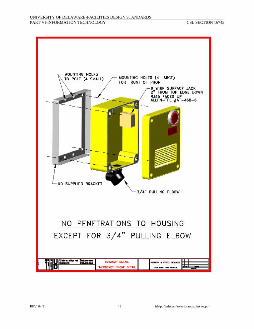
2. Locations for Emergency Phones on buildings shall include one (1) 3/4-inch EMT sleeve installed thru the exterior wall for routing of AC power conductors for the installed blue-light. The installation shall also include one (1) 3/4-inch EMT sleeve installed thru the exterior wall for routing of the 4-pair telecommunications cable for dial tone to the phone itself. For 4-pair cable routing to the emergency phone, install a ¾” metallic stub-out below the emergency phone, then into the bottom of the emergency phone enclosure. This penetration into the emergency phone enclosure must be done off-center because of the physical location of internal phone electronics within the enclosure. No other penetrations of the enclosure shall be acceptable. If other penetrations are attempted without UD-NSS approval, the contractor shall be responsible for the cost of a new emergency phone.
3. For Emergency Phones mounted directly on buildings, the back enclosure of the phone itself shall be secured to the building exterior wall via the four supplied screw mounting holes. No other penetrations of the enclosure shall be acceptable. If other penetrations of the emergency phone enclosure are attempted, the contractor shall be responsible for the cost of a new emergency phone
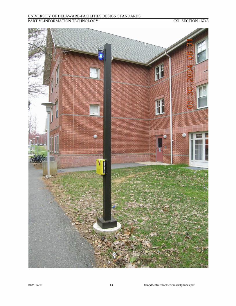
4. For Emergency Phone locations beyond the footprint of the building (not on exterior wall), install Hubbell Inc. Steel-Straight-Square poles for mounting of the emergency phone and the blue light assembly.
UNIVERSITY OF DELAWARE-FACILITIES DESIGN STANDARDS PART VI-INFORMATION TECHNOLOGY CSI: SECTION 16743
REV. 04/11 4 fds\pdf\infotech\exteriorassistphones.pdf
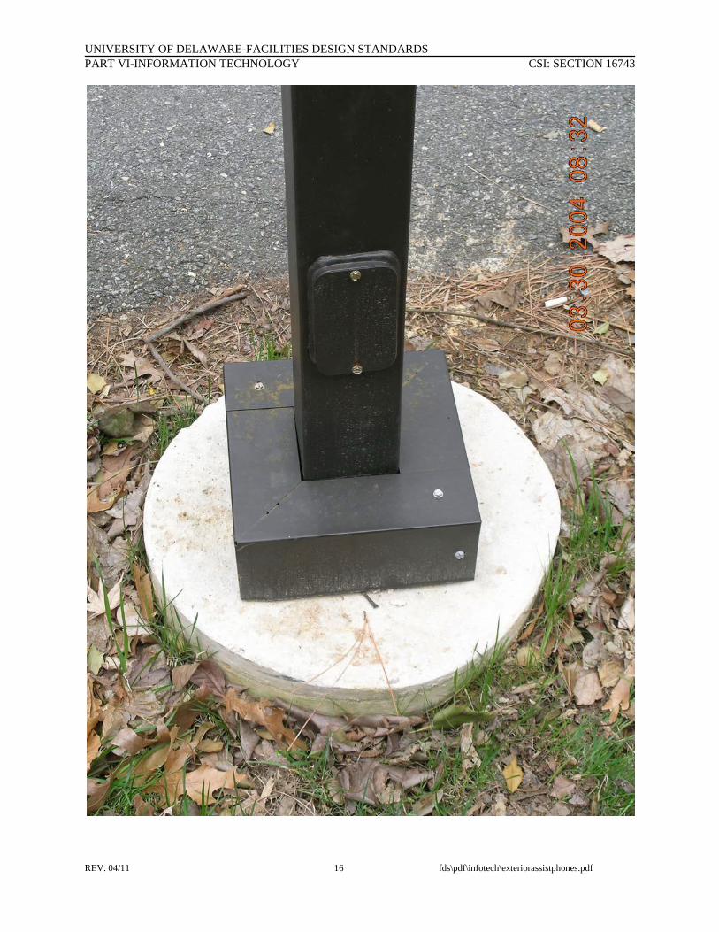
5. For pole mounted locations, install two (2) one-inch schedule 40 conduits to be used for AC power and the 4-pair cable installation. Install an 18” diameter concrete tube/base for the conduits to be routed up into, and the pole to be mounted upon.
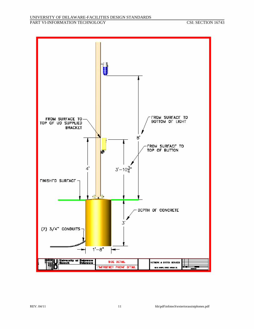
6. Upon completion of the Hubbell pole, the Blue Light shall be installed at a height of 8ft. – 0” to the bottom of the light fixture from finished grade/paving. The blue light circuit shall be controlled by an installed photo cell unit.
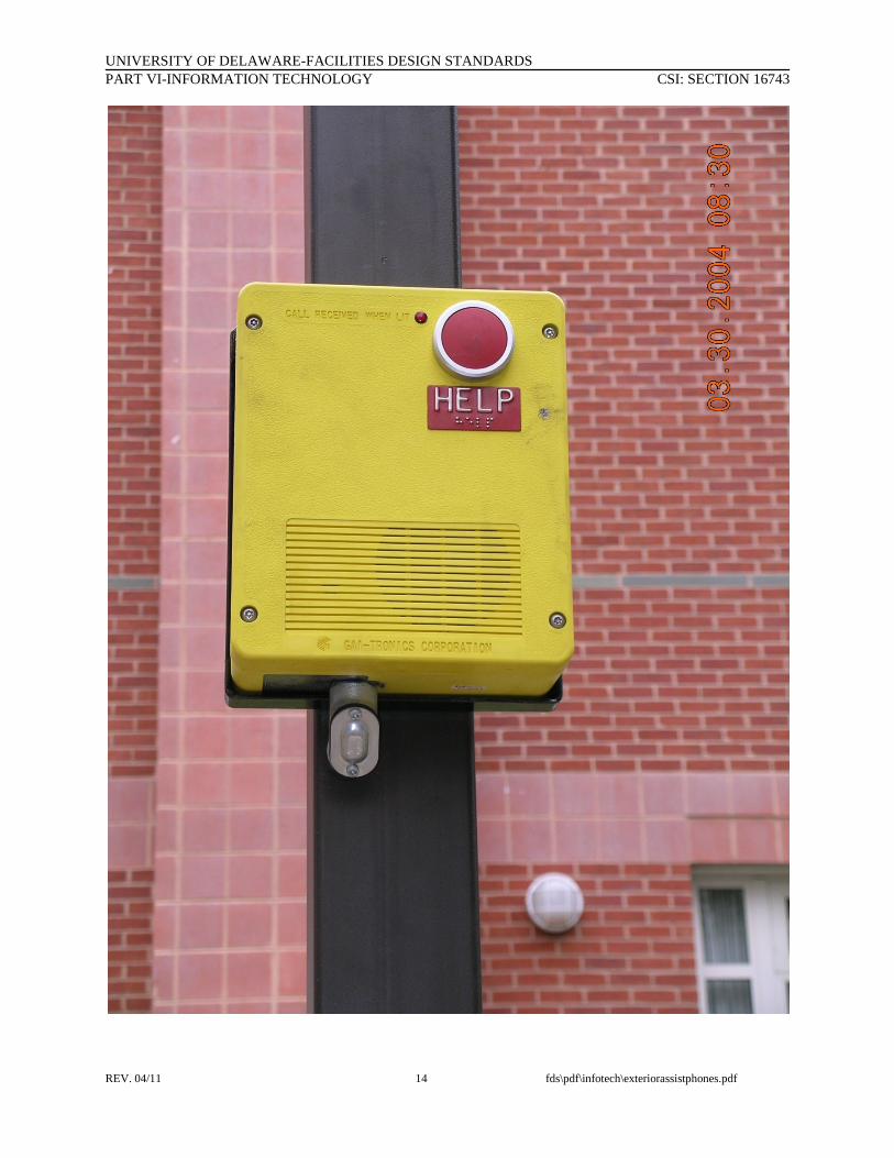
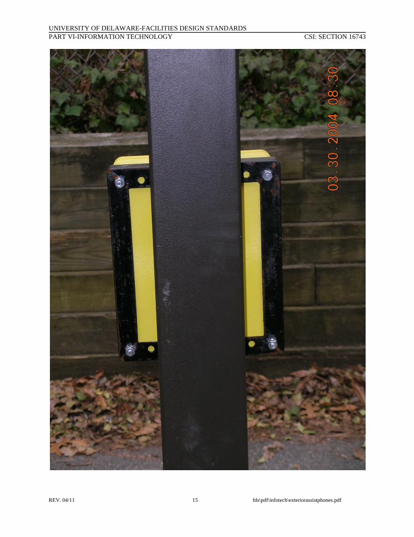
7. All pole mounted emergency phones shall be installed to the poles using a UD Network & Systems Services provided Emergency Phone mounting bracket. This mounting bracket shall be installed so that the top of the bracket is at 48” above grade. When the Emergency Phone is installed, the call button shall be at the height of 47-1/14” above the pavement, satisfying ADA requirements. The mounting bracket shall be secured to the pole by way of screws that shall be installed in the middle of the bracket. The emergency phone back enclosure shall be installed onto the bracket using the four supplied screw mounting holes. No other penetrations of the enclosure shall be acceptable. If other penetrations of the emergency phone enclosure are attempted, the contractor shall be responsible for the cost of a new emergency phone.
8. For 4-pair cable routing to the Emergency Phone, install a ¾” metallic conduit stub-out below the emergency phone mounting plate on the face of the pole, then into the bottom of the emergency phone enclosure. This penetration into the emergency phone enclosure must be done off-center because of the physical location of internal phone electronics within the enclosure. No other penetrations of the enclosure shall be acceptable. If other penetrations are attempted without UD-NSS approval, the contractor shall be responsible for the cost of a new emergency phone.
9. Utilize 4-pair CMR or EMP CAT5E rated Mohawk cable for phones mounted directly on exterior walls of buildings.
10. Utilize Mohawk 4-pair outside rated CAT5E cable for locations outside the footprint of the building at Hubbell Pole locations.
11. All emergency phone cabling that serves locations outside the footprint of the building shall be installed with lightning protection within the building itself, and shall be bonded/grounded accordingly. The lightning protection module shall be the Porta-Systems #504PX26GT, as per the products section of this specification.
12. The 4-pair cable routed into the phones at all locations shall terminate in an Allen-Tel #AT-468-6, surface mount jack with a single RJ-11 jack, which the internal emergency phone RJ-11 cord shall be connected to for dial-tone.
UNIVERSITY OF DELAWARE-FACILITIES DESIGN STANDARDS PART VI-INFORMATION TECHNOLOGY CSI: SECTION 16743
REV. 04/11 5 fds\pdf\infotech\exteriorassistphones.pdf
PART 3 – INSTALLATION OF CONDUIT
A. INSTALLATION OF CONDUIT FOR POLE LOCATIONS
1. Install two (2) one-inch schedule-40 conduits for each emergency phone location. One shall be used for AC power conductor routing, and one shall be used for the 4-pair telecommunications cable for dial-tone.
2. Install one (1) 18” diameter concrete tube/base at each emergency phone location as a mounting location for the Hubbell Pole.
3. All conduits shall terminate in manholes or at buildings as determined by UD Network & Systems Services.
4. The center of the conduit duct-bank between manholes shall be graded slightly down towards both manholes with a nominal grade of 3” per 100 ft.
5. The top of the duct-bank shall be a minimum of 36” below grade.
6. There shall be 1” of granular select backfill on the bottom of the trench beneath the duct-bank.
7. There shall be granular select backfill tamped between and around all ducts.
8. There shall be 12” of granular select backfill installed and tamped above the top row of ducts.
9. Backfill and restoration of the trench, around each manhole, and at buildings shall be accomplished by way of tamping of the backfill in minimum 18” lifts.
10. There shall be an orange warning tape placed approximately 24” above the duct-bank, as a warning to personnel involved in future excavations, indicating that Communications cabling is buried below.
11. All conduit splicing/interconnects shall first be cleaned with an approved PVC conduit cleaner around the entire circumference of the straight and bell sides of the conduit. All cleaned surfaces shall be completely “primed” with an approved PVC Purple Primer, then properly bonded together using approved PVC Cement, which shall also be applied around the entire circumference of the straight and bell sides of the conduit.
12. Where transitional changes are required for horizontal and vertical directions, use long field sweeping bends only. The minimum bend radius for all 1” conduits shall be 10”.
UNIVERSITY OF DELAWARE-FACILITIES DESIGN STANDARDS PART VI-INFORMATION TECHNOLOGY CSI: SECTION 16743
REV. 04/11 6 fds\pdf\infotech\exteriorassistphones.pdf
13. All 1” conduit entry into manholes shall be accomplished by way of core-boring 2” holes through the concrete walls of the manholes to enable a tight and proper seal around all conduits. All conduits shall be centered in the cored holes, and properly sealed with hydraulic cement upon installation on both sides of the manhole walls, so as to provide a complete fill of the surrounding cavity around each conduit and core.
14. All conduit entry into handholes shall be accomplished utilizing a Greenlee Hydraulic Knockout Punch Driver of appropriate size, as per Quazite Field Applications Instruction Sheets for handholes. All conduits shall be terminated in holes cut out in appropriate walls with PVC glue-to-male-threaded couplers.
PART 4 – INSTALLATION OF TWISTED PAIR CABLING
A. INSTALLATION OF TWISTED PAIR CABLING
1. Installation shall include delivery, unloading, setting in place, fastening to walls, floors, ceilings, or other structures where required, interconnecting wiring of system components, equipment alignment and adjustment, and all other related work whether or not expressly defined herein. Installation shall be performed in accordance with applicable standards, codes, requirements and recommendations of National, State, and Local authorities having jurisdiction, and the N.E.C. (National Electrical Code). All boxes, equipment, etc., shall be installed plumb and square, and firmly secured in place unless requirements of portability dictate otherwise.
2. In the installation of equipment and cable, consideration shall be given not only to operational efficiency, but also to overall aesthetic factors.
3. If there are areas where sleeves are required through walls or in concrete slabs, the contractor is responsible for providing those sleeves as required to accommodate his work. All holes must be core bored. After completion of the Communications Cabling System, the contractor shall fire seal all communications sleeves with a UL approved fire stop in accordance with the NFPA (National Fire Protection Agency).
B. TWISTED PAIR CABLING TESTING
1. Before Acceptance Tests are scheduled, the Contractor shall perform his own system checkout. The Contractor shall furnish all required test equipment and shall perform all work necessary to determine and/or modify performance of the system to meet the requirements of this specification. This work shall include the following.
a. End-to-End tests of the wiring of each 4-pair telecommunications cable shall include continuity and anti-continuity, pair integrity, attenuation, polarity, and NEXT. The tests shall be performed at the EIA/TIA Category 3 level.
UNIVERSITY OF DELAWARE-FACILITIES DESIGN STANDARDS PART VI-INFORMATION TECHNOLOGY CSI: SECTION 16743
REV. 04/11 7 fds\pdf\infotech\exteriorassistphones.pdf
b. Submit paper and electronic format test results in .flw format to the UD Department of Network & Systems Services upon completion of project.
PART 5 – MATERIALS AND EQUIPMENT
A. MATERIALS AND EQUIPMENT
1. A complete information package of all materials and equipment shall be submitted to the University of Delaware for review by the Department of Network & Systems Services for approval four (4) weeks prior to installation. Equipment shall include, but may not necessarily be limited to, the following.
2. The equipment and components included in this specification are manufactured and/or distributed by the Siemon Co, Mohawk Cable Corp., Graybar, Anixter, or similar.
3. All materials and equipment supplied shall be new and shall meet or exceed the latest published specifications of the manufacturer in all respects, and shall be UL (Underwriters Laboratory) approved. The Contractor shall supply the latest model available at the time of bidding of each piece of equipment.
4. Equipment shall include, but may not be limited to, the following.
B. TWISTED PAIR CABLING PRODUCTS, MATERIALS AND EQUIPMENT
1. TWISTED PAIR OUTSIDE PLANT COMMUNICATIONS CABLE
a. Outside Locations at pole locations - Mohawk Cable Corp. #M57561- 4-Pair, outside/duct rated CAT5E cable for Campus or Emergency Phones located in the outside environment.
b. Locations on building exterior walls – Mohawk Cable Corp #M56167 riser rated cable, or #M56168 plenum rated cable.
2. LIGHTNING PROTECTION AND TERMINATION MODULES
a. Porta-Systems Corp. #504PX26GT, 6-pair Protector Pack – to be installed on all Assist phone cables that serve phones located outside the footprint of the building (exterior).
3. EMERGENCY PHONE EQUIPMENT AND PRODUCTS
a. Emergency Phone, Gaitronics S.M.A.R.T. Phone #293-003, shall be supplied by the University Of Delaware Department of Network & Systems Services. UD-NSS will provide the back boxes/enclosures to the contractor so that the conduit stub into the bottom of the enclosure for 4-pair cable routing can be coordinated
UNIVERSITY OF DELAWARE-FACILITIES DESIGN STANDARDS PART VI-INFORMATION TECHNOLOGY CSI: SECTION 16743
REV. 04/11 8 fds\pdf\infotech\exteriorassistphones.pdf
and installed. When installed on Hubbell Poles, the Emergency Phone shall be mounted to a mounting bracket, which will also be supplied by UD-NSS. There shall be no holes drilled thru the Emergency Phone back box/enclosure. The use of the mounting bracket will allow proper mounting of the phone to the Hubbell pole.
4. HUBBELL POLES
a. Hubbell Pole for locations outside the footprint of the building shall utilize #SSS-10-40-1-AX-DB (Square, Straight, Steel, 10ft. long, 4” shaft, 11-gauge, single-sided, bronze in color).
5. CONDUIT
a. Standard PVC Schedule-40 conduits, sized at one-inch. Utilize PVC cleaner, primer, and glue as defined previously in this specification.
6. BLUE LIGHT
a. Fixture Body & Guard – Shall be Rab Lighting Corp. #VXBR100DG
b. Fixture Globe – Shall be Rab Lighting Corp. #GL100B, blue in color
c. Photo Cell – Intermatic Corp. #K4121C, 120V/1800W, non-swivel
d. Bulbs – Phillips #FLE15HT3/2/841, GE Spiral, Compact Fluorescent 15W/60W Equivalent
UNIVERSITY OF DELAWARE-FACILITIES DESIGN STANDARDS PART VI-INFORMATION TECHNOLOGY CSI: SECTION 16743
REV. 04/11 9 fds\pdf\infotech\exteriorassistphones.pdf
ARTICLE II EXTERIOR EMERGENCY PHONE
SYSTEM INSTALLATION
PART 1 – EMERGENCY PHONE SYSTEM SCOPE OF WORK
A. SCOPE OF WORK AND RESPONSIBLITIES FOR THE CONTRACTOR:
1. The scope of work for the Contractor shall include all labor, materials, equipment, and services necessary for the installation of a complete emergency phone and associated cabling system including, but not limited to, schedule 40 conduits, concrete base, mounting poles and brackets, AC power and cabling, lighting, telecommunications cabling, termination hardware, lightning projection modules, and other related equipment as required. The scope of work shall also include termination, testing, and labeling of the entire systems. The contractor shall contact the University Department of Network & Systems Services prior to terminating any cabling within the Telecommunications Rooms , so that proper layout of all equipment is coordinated and verified.
2. EXTERIOR BUILDING EMERGENCY PHONE LOCATIONS
a. On Building - Install xxx (x) Emergency Phone and xxx (x) Blue Lights and associated materials on the XXXX Wall of XXXX Building, as per supplied CAD drawing, and UD Network & Systems Services walk-thru. Install associated conductors for AC power, 4-pair telecommunications cabling, one-inch sleeves, and all necessary equipment.
b. Beyond footprint of building - Install xxx (x) Hubbell Pole, and xxx (x) Emergency Phone Blue Lights and associated materials at a pole mount location near XXX building, as per supplied CAD drawing and UD Network & Systems walk-thru. Install associated conductors for AC power, 4-pair telecommunications cabling, and all necessary equipment.
c. Install two (2) 1-inch schedule 40 conduits from XXX Manhole or XXXX Building, to the Emergency Phone pole location, to be used for AC power and the 4-pair cable installation.
d. Install xxx (x) 18” mounting tube/base to the installation of the Hubbell Pole.
e. Install one (1) 4-pair cable from each phone location, thru the 1” PVC conduit, to XXX Building Telecommunications Room XXX. Provide and install lightning protection, terminate, and bond/ground the protector back to the telecommunications room bonding bus-bar by way of green #6 braided conductor.
UNIVERSITY OF DELAWARE-FACILITIES DESIGN STANDARDS PART VI-INFORMATION TECHNOLOGY CSI: SECTION 16743
REV. 04/11 10 fds\pdf\infotech\exteriorassistphones.pdf
PART 2 – SUBMITTALS
A. GENERAL SUBMITTAL INFORMATION
1. At the completion of the installation, the Contractor shall provide one (1) copy of each of the following.
2. Equipment manufacturer's operation and maintenance manuals for each piece of equipment.
3. Samples of proposed equipment may be required by the University of Delaware prior to any contracts.
4. The Bidder shall include a statement of warranty on the entire system and on the individual pieces of equipment. The system warranty shall be for a minimum of one (1) year from the date of system acceptance by the Owner. This warranty shall obligate the Contractor to provide all equipment, material and labor, at no charge to the Owner, during the warranty period in the event of system or equipment malfunction. All manufacturers’ equipment warranties shall be activated in the Owner's name and shall commence on the date of system acceptance. In the case of Contractor modified equipment, the manufacturer's warranty is normally voided. In such cases, the Contractor shall provide the Owner with a warranty equivalent to that of the original manufacturer.
--END OF SECTION--
UNIVERSITY OF DELAWARE-FACILITIES DESIGN STANDARDS PART VI-INFORMATION TECHNOLOGY CSI: SECTION 16743
REV. 04/11 11 fds\pdf\infotech\exteriorassistphones.pdf
UNIVERSITY OF DELAWARE-FACILITIES DESIGN STANDARDS PART VI-INFORMATION TECHNOLOGY CSI: SECTION 16743
REV. 04/11 12 fds\pdf\infotech\exteriorassistphones.pdf
UNIVERSITY OF DELAWARE-FACILITIES DESIGN STANDARDS PART VI-INFORMATION TECHNOLOGY CSI: SECTION 16743
REV. 04/11 13 fds\pdf\infotech\exteriorassistphones.pdf
UNIVERSITY OF DELAWARE-FACILITIES DESIGN STANDARDS PART VI-INFORMATION TECHNOLOGY CSI: SECTION 16743
REV. 04/11 14 fds\pdf\infotech\exteriorassistphones.pdf
UNIVERSITY OF DELAWARE-FACILITIES DESIGN STANDARDS PART VI-INFORMATION TECHNOLOGY CSI: SECTION 16743
REV. 04/11 15 fds\pdf\infotech\exteriorassistphones.pdf
UNIVERSITY OF DELAWARE-FACILITIES DESIGN STANDARDS PART VI-INFORMATION TECHNOLOGY CSI: SECTION 16743
REV. 04/11 16 fds\pdf\infotech\exteriorassistphones.pdf