external beam delivery systems - argonne national laboratory · 2014-10-31 · external beam...
TRANSCRIPT

Karl L. Prado, Ph.D., FACR, FAAPM
Professor, Department of Radiation Oncology
External Beam Delivery Systems
Argonne National Laboratory Course: 3DCRT for Technologists
X-Ray Production
X rays, fundamentals, etc.
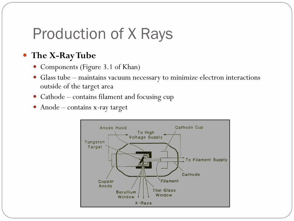
Production of X Rays
The X-Ray Tube Components (Figure 3.1 of Khan)
Glass tube – maintains vacuum necessary to minimize electron interactions outside of the target area
Cathode – contains filament and focusing cup
Anode – contains x-ray target
The X-Ray Tube
The Cathode
Tungsten filament (high melting point – 3370 C)
Thermionic emission – electron production as a consequence of
heating
Focusing cup – “directs” electrons to anode
Dual filaments (diagnostic tubes) – necessary to balance small
focal spots and larger tube currents
The X-Ray Tube
The Anode
Tungsten target
High melting point
High Z (74) – preferred since bremsstrahlung production Z2
Heat dissipation
Copper anode – heat conducted outside glass into oil / water / air
Rotating anode (diagnostic tubes) – larger dissipation area
Anode hood – copper and tungsten shields intercept stray
electrons and x rays

Basic X-Ray Circuit
Simplified diagram (Khan Figure 3.3)
Consists of two parts: High-voltage circuit – provides x-ray tube accelerating potential Filament circuit – provides filament current
X-Ray Production
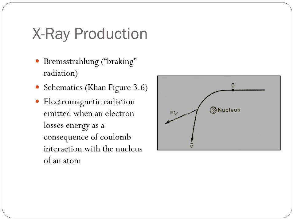
Bremsstrahlung (“braking”
radiation)
Schematics (Khan Figure 3.6)
Electromagnetic radiation
emitted when an electron
losses energy as a
consequence of coulomb
interaction with the nucleus
of an atom
X-Ray Energy Spectrum
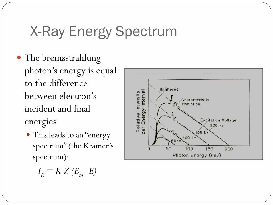
The bremsstrahlung
photon’s energy is equal
to the difference
between electron’s
incident and final
energies
This leads to an “energy
spectrum” (the Kramer’s
spectrum):
IE = K Z (Em- E)
X-Ray Angular Distribution
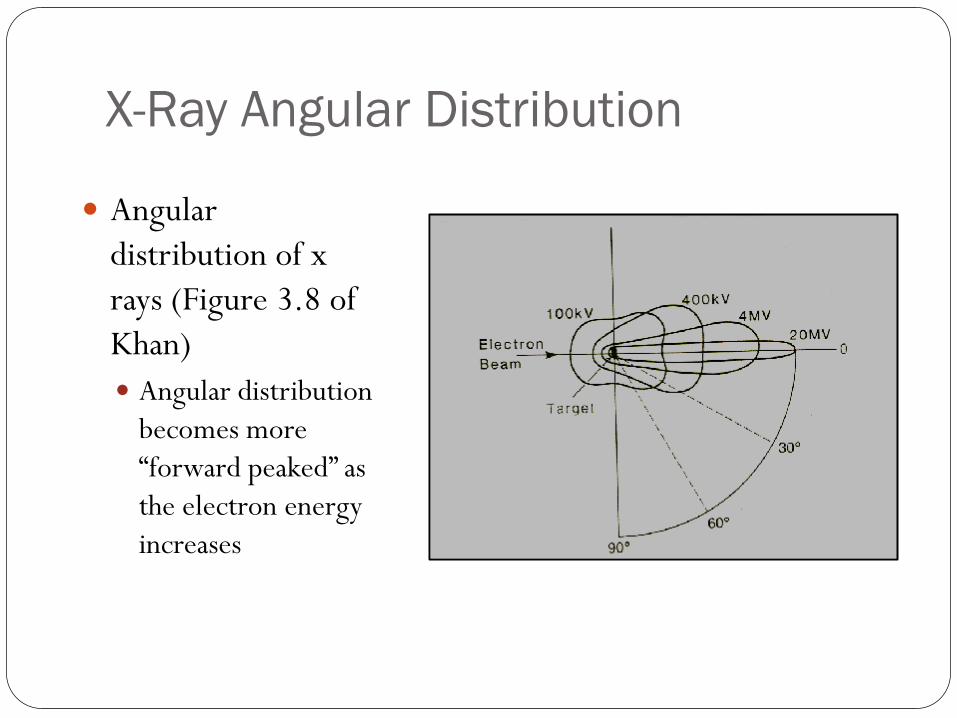
Angular
distribution of x
rays (Figure 3.8 of
Khan)
Angular distribution
becomes more
“forward peaked” as
the electron energy
increases

X-Ray Spectrum
X-Ray Spectrum (Figure
3.9 of Khan)
Composite of Kramer’s
spectrum and
characteristic x rays
Filtration reduces lower-
energy component
Rule of thumb is average
energy ≈ 1/3 maximum
energy
Half Value Layer (HVL) is
a common descriptor
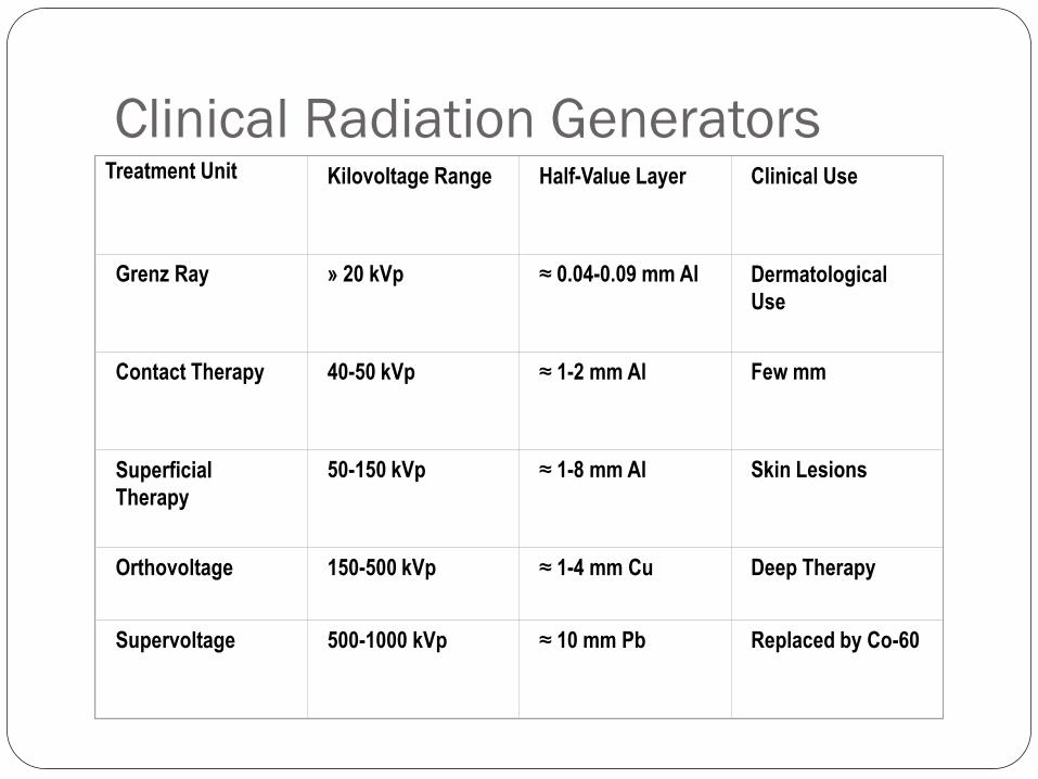
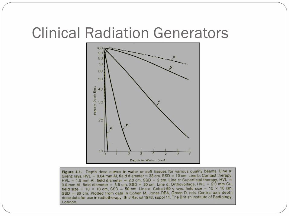
Clinical Radiation Generators Treatment Unit
Kilovoltage Range
Half-Value Layer
Clinical Use
Grenz Ray
» 20 kVp
≈ 0.04-0.09 mm Al
Dermatological
Use
Contact Therapy
40-50 kVp
≈ 1-2 mm Al
Few mm
Superficial
Therapy
50-150 kVp
≈ 1-8 mm Al
Skin Lesions
Orthovoltage
150-500 kVp
≈ 1-4 mm Cu
Deep Therapy
Supervoltage
500-1000 kVp
≈ 10 mm Pb
Replaced by Co-60
Clinical Radiation Generators
Co-60 Teletherapy Units
Co-60 sources, teletherapy units – characteristics, operations, safety
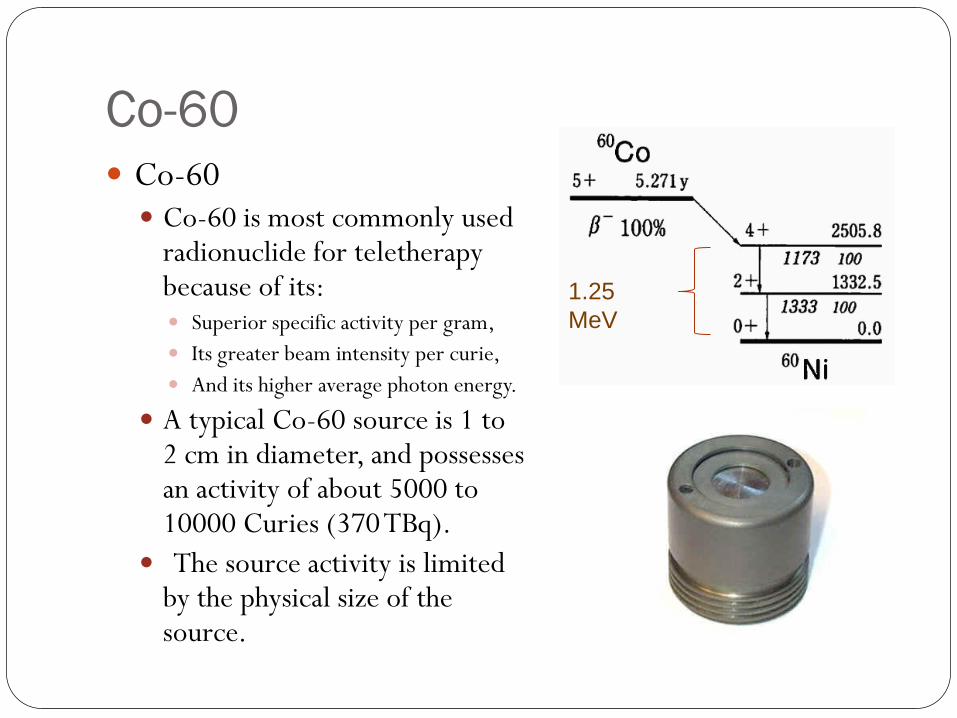
Co-60 Co-60 Co-60 is most commonly used
radionuclide for teletherapy because of its: Superior specific activity per gram,
Its greater beam intensity per curie,
And its higher average photon energy.
A typical Co-60 source is 1 to 2 cm in diameter, and possesses an activity of about 5000 to 10000 Curies (370 TBq).
The source activity is limited by the physical size of the source.
1.25
MeV
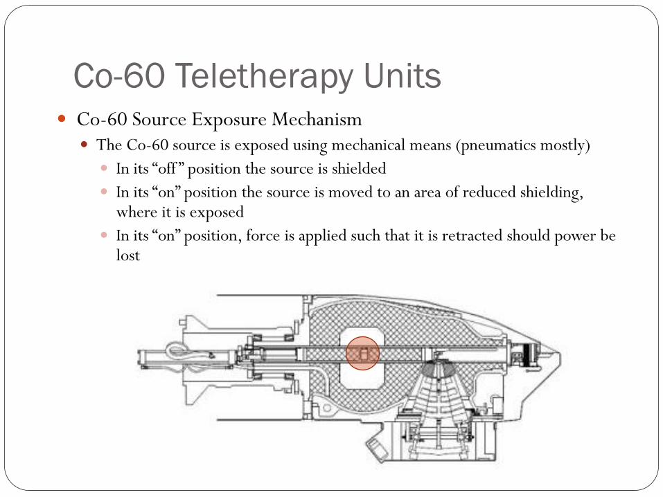
Co-60 Teletherapy Units Co-60 Source Exposure Mechanism
The Co-60 source is exposed using mechanical means (pneumatics mostly)
In its “off ” position the source is shielded
In its “on” position the source is moved to an area of reduced shielding, where it is exposed
In its “on” position, force is applied such that it is retracted should power be lost
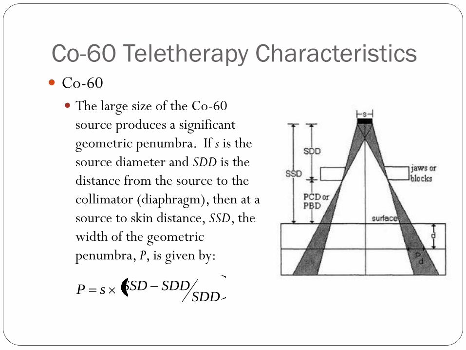
Co-60 Teletherapy Characteristics Co-60
The large size of the Co-60
source produces a significant
geometric penumbra. If s is the
source diameter and SDD is the
distance from the source to the
collimator (diaphragm), then at a
source to skin distance, SSD, the
width of the geometric
penumbra, P, is given by:
SDDSDDSSDsP
Co-60 Teletherapy Characteristics
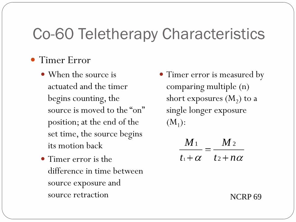
Timer Error
When the source is
actuated and the timer
begins counting, the
source is moved to the “on”
position; at the end of the
set time, the source begins
its motion back
Timer error is the
difference in time between
source exposure and
source retraction
Timer error is measured by
comparing multiple (n)
short exposures (M2) to a
single longer exposure
(M1):
nt
M
t
M
2
21
1
NCRP 69
Co-60 Teletherapy Characteristics
Beam characteristics
PDD at 10 cm depth,
10x10 cm field
55.6%, Co-60, 80 SSD
66.9%, 6 MV, 100 SSD
Penumbrae (80%-20%)
1.2 cm Co-60 typical
0.4 cm 6 MV typical
Radiation Safety
Five-Year Inspection
Requirement in the USA by
Nuclear Regulatory
Commission
Source is replaced
Treatment Unit is refurbished
Emergency Procedures
Manual source insertion –
yearly exercise
Radioactive source
Possible restrictions of
pregnant workers

The Linear Accelerator
Electron acceleration, microwave production, accelerator
components,

The Linear Accelerator
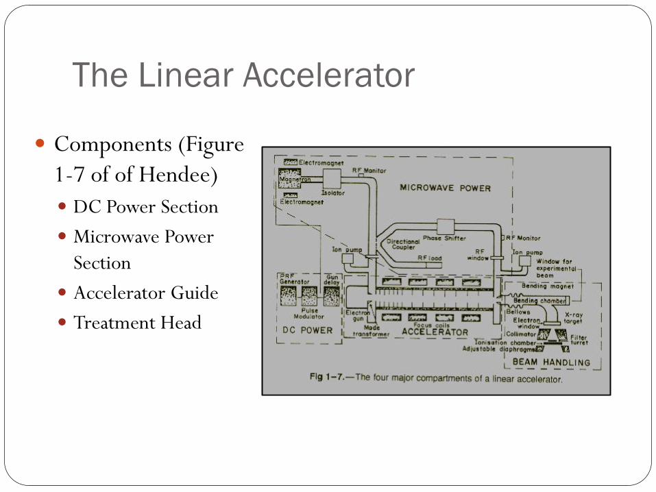
The Linear Accelerator
Components (Figure
1-7 of of Hendee)
DC Power Section
Microwave Power
Section
Accelerator Guide
Treatment Head
The Linear Accelerator
DC Power Section
Produces properly-shaped pulses of DC power; these pulses are
shaped in the pulse-forming network of the modulator and delivered
to the electron gun and microwave power section at the proper
frequency through a high-voltage switching device (the
thyratron).
The Linear Accelerator
Microwave Power Section – Provides microwave power
amplification (utilizing either a magnetron or klystron) and
transmits the amplified microwaves to the accelerator
guide.
Accelerator Guide – A cylindrical tube in which
electrons, injected by the electron gun, are accelerated
by the amplified microwaves. The accelerated electrons
exit the waveguide and enter the treatment head.
The Linear Accelerator
Treatment Head
Contains the beam shaping, steering, and control components
of the linear accelerator. These components are: the bending
magnet, x-ray target, electron scattering foils (most accelerators),
x-ray flattening filter, dose monitoring chambers, and beam
collimation system.
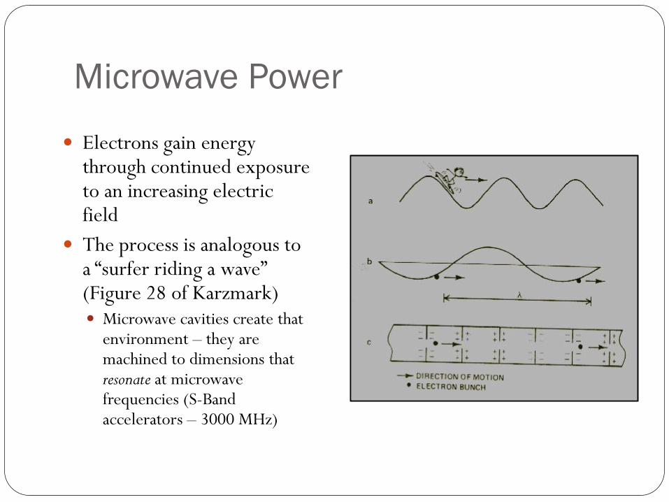
Microwave Power
Electrons gain energy through continued exposure to an increasing electric field
The process is analogous to a “surfer riding a wave” (Figure 28 of Karzmark) Microwave cavities create that
environment – they are machined to dimensions that resonate at microwave frequencies (S-Band accelerators – 3000 MHz)
Microwave Power
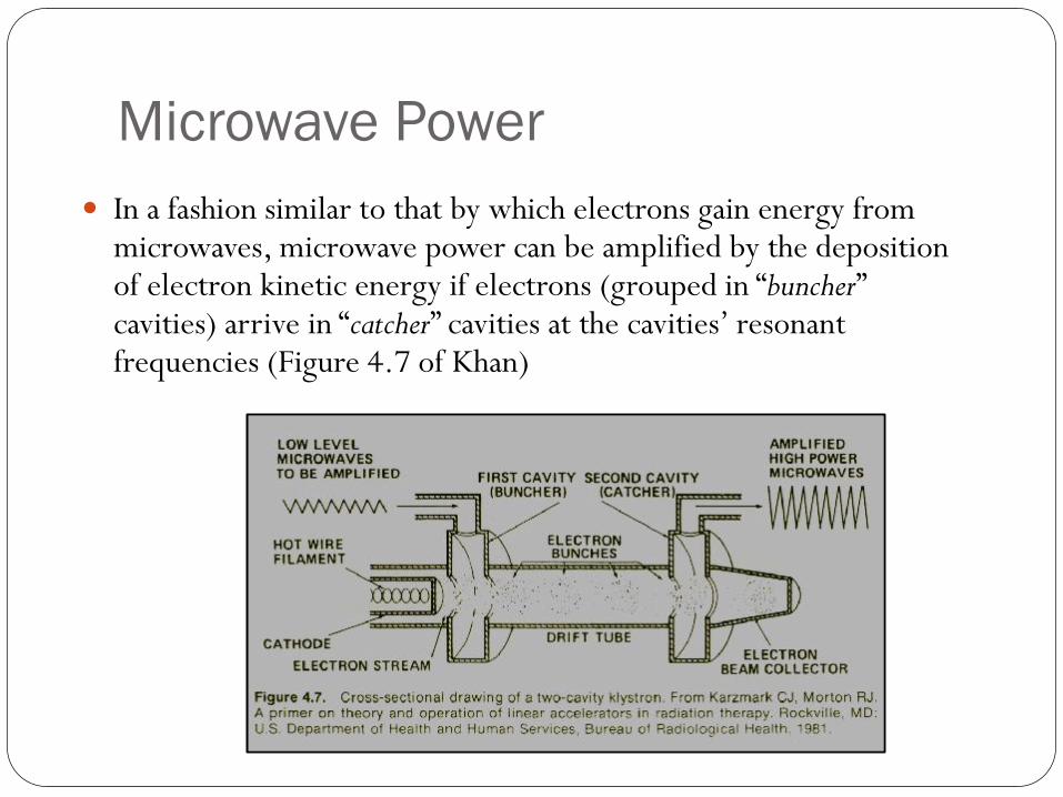
In a fashion similar to that by which electrons gain energy from microwaves, microwave power can be amplified by the deposition of electron kinetic energy if electrons (grouped in “buncher” cavities) arrive in “catcher” cavities at the cavities’ resonant frequencies (Figure 4.7 of Khan)
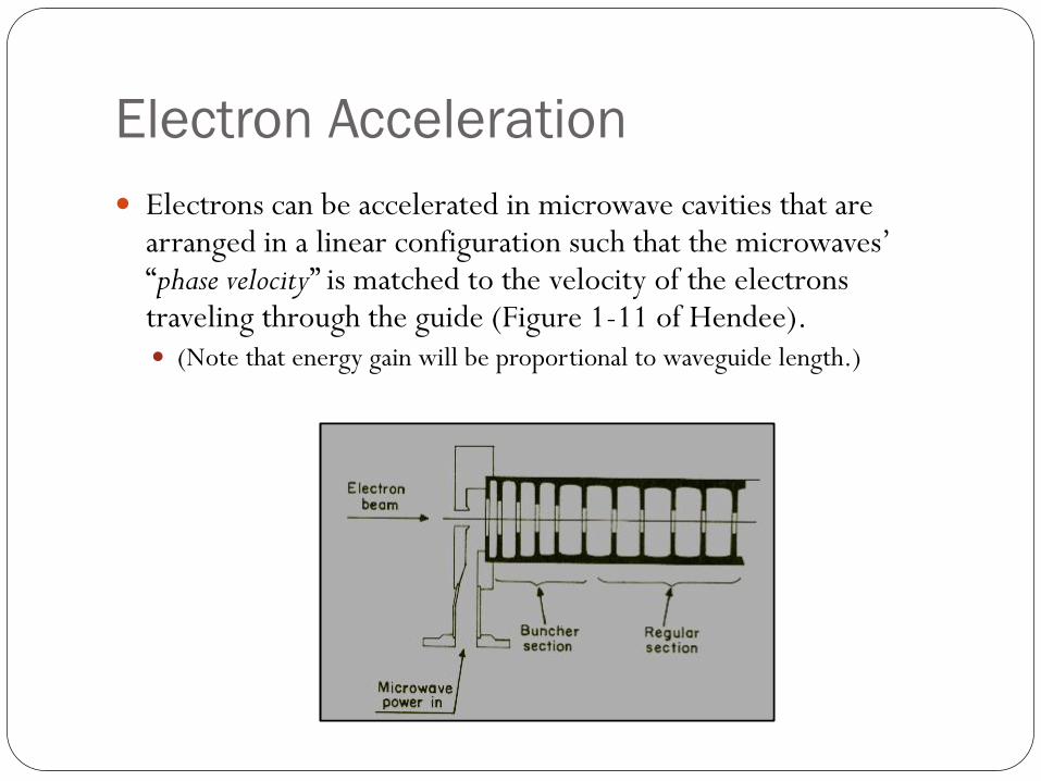
Electron Acceleration
Electrons can be accelerated in microwave cavities that are arranged in a linear configuration such that the microwaves’ “phase velocity” is matched to the velocity of the electrons traveling through the guide (Figure 1-11 of Hendee). (Note that energy gain will be proportional to waveguide length.)

The Treatment Head
Shielded Housing – lead shielding reduces unwanted radiation
Bending Magnet – provides electron energy selection the magnetic field intensity B
is set such that electrons possessing the appropriate energy (momentum mev) are bent through the radius r that allows passage through the magnet’s exit port:
mev B r
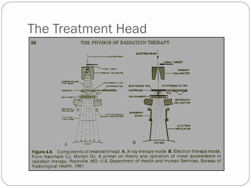
The Treatment Head

The Treatment Head
X-Ray Target – transmission-type tungsten target in
which electron produce bremsstrahlung radiation;
inserted only during x-ray beam production, removed
during electron-beam production
Flattening Filter – (photon beams) metal filter placed in
the x-ray beam to compensate for the “forward peaked”
photon distribution and produce a “flat” beam

The Treatment Head
Scattering Foils – (electron beams) thin metallic foils
inserted in the electron beam to spread the beam and
obtain a uniform electron fluence
Monitoring Chambers – transmission ionization
chambers used to monitor dose rate, total integrated
dose and beam symmetry.
Collimation System – fixed and movable beam limiting
devices, normally made of lead, used to shape and size
the beam
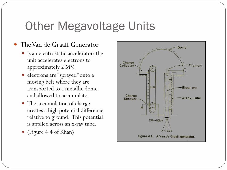
Other Megavoltage Units
The Van de Graaff Generator is an electrostatic accelerator; the
unit accelerates electrons to approximately 2 MV.
electrons are “sprayed” onto a moving belt where they are transported to a metallic dome and allowed to accumulate.
The accumulation of charge creates a high potential difference relative to ground. This potential is applied across an x-ray tube.
(Figure 4.4 of Khan)

Other Megavoltage Units The Betatron
Electrons contained in an evacuated hollow “donut” are accelerated by an
alternating magnetic field of increasing intensity
Electrons are “removed” from their orbit after attaining the proper energy by
introducing a sudden reduction in the magnetic field; electrons are then allowed
to strike either an x-ray target or scattering foils

Other Megavoltage Units The Cyclotron
Two hollow semi-circular electrodes (called “Dees”) are mounted between the poles of an electromagnet; an alternating potential is applied to the dees which are separated by a small gap
Positive ions (e.g. protons) are released into the center of the dees and are attracted to the negative dee where they enter into a circular orbit.
The alternating potential is timed so that the electric fields change
direction as the particles emerge from the first dee. The particles are
then accelerated to the second dee where the process is repeated.
Each time the positive ions traverse a gap they gain energy. As they gain
energy, the radius of their circular orbit increases until they are
removed.
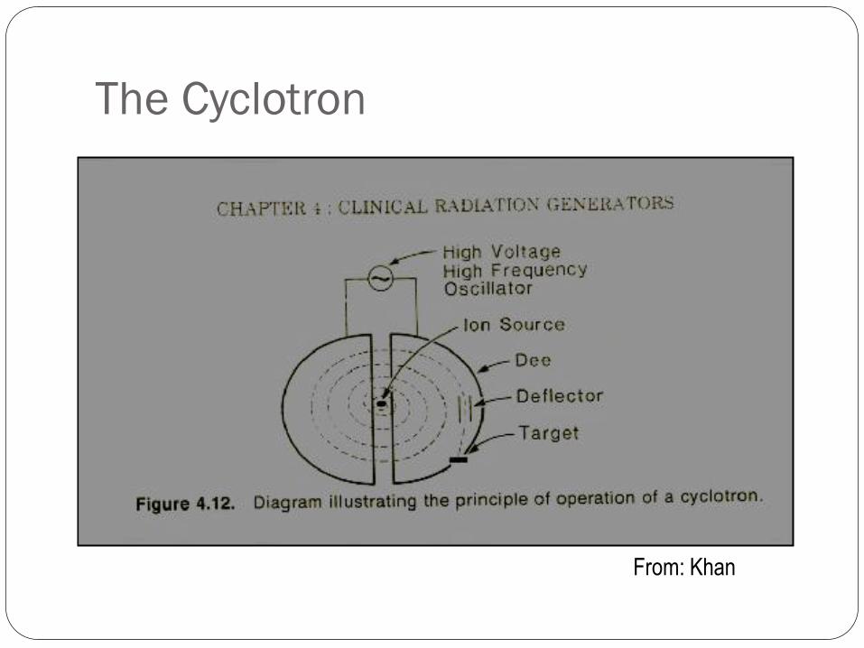
The Cyclotron
From: Khan
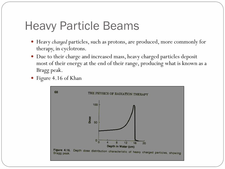
Heavy Particle Beams Heavy charged particles, such as protons, are produced, more commonly for
therapy, in cyclotrons.
Due to their charge and increased mass, heavy charged particles deposit most of their energy at the end of their range, producing what is known as a Bragg peak.
Figure 4.16 of Khan
Summary
External Beam Therapy Units
Most Important Components
Radionuclide Teletherapy Units: Co-60 Teletherapy
X-Ray Units
X-ray production
The Linear Accelerator
Other External Beam Units

Thank You