external corrosion of oil and natural gas pipelines
TRANSCRIPT

External Corrosion ofOil and Natural Gas PipelinesJohn A. Beavers and Neil G. Thompson, CC Technologies
PIPELINES play an extremely important rolethroughout the world as a means of transportinggases and liquids over long distances from theirsources to the ultimate consumers. The generalpublic is not aware of the number of pipelinesthat are continually in service as a primarymeansof transportation. A buried operating pipeline israther unobtrusive and rarely makes its presenceknown except at valves, pumping or compressorstations, or terminals. In the United States, therewere approximately 217,000 km (135,000 mi)of hazardous liquid transmission pipelines,34,000 km (21,000 mi) of crude oil gatheringpipelines, 483,000 km (300,000 mi) of naturalgas transmission pipelines, and 45,000 km(28,000 mi) of natural gas gathering pipelines in2000 (Ref 1–3). There were approximately 60major natural gas transmission pipeline opera-tors and 150 major hazardous liquid pipelineoperators in the United States in 1998 (Ref 4).The first oil pipeline, which was 175 km
(109 mi) in length and 152 mm (6 in.) in dia-meter, was laid from Bradford to Allentown, PAin 1879 (Ref 5). Since the late 1920s, virtually alloil and gas pipelines have been made of weldedsteel. Although the first cross-country pipelinethat connected some major cities was laid in1930, it was not until World War II that large-scale pipelines were laid connecting differentregions of the country. In the 1960s, larger-diameter pipelines ranging from 813 to 914 mm(32 to 36 in.) were built. Discovery of oil onAlaska’s North Slope resulted in the constructionof the country’s largest pipeline, the Trans-AlaskaPipeline System, with a 1219 mm (48 in.)diameter and 1287 km (800 mi) length. Demandcontinues to add more miles of pipelines.Table 1 provides a summary of the major
accidents reported to the U.S. Department ofTransportation by the operators for the 6-yearperiod between 1994 and 1999 (Ref 6). The datashow that for transmission pipeline systems (bothhazardous liquid and natural gas), approximately25% of all reported accidents were due to corro-sion. Of the hazardous liquid pipeline accidentscaused by corrosion, 65% were due to externalcorrosion and 34%were due to internal corrosion.For natural gas transmission pipeline accidents,
36% were caused by external corrosion and 63%were caused by internal corrosion. For natural gasdistribution pipeline accidents, only approxi-mately 4% of the total accidents were caused bycorrosion, and the majority of those were causedby external corrosion. The accidents reported inTable 1 are for major accidents that resulted ininjury, fatality, or more than $50,000 in propertydamage. In addition to the reportable accidents,an average of 8000 corrosion leaks per year arerepaired on natural gas transmission pipelines(Ref 7), and 1600 spills per year are repaired andcleaned up for liquid product pipelines.In a summary report for incidents between
1985 and 1994, corrosion accounted for 28.5% ofpipeline incidents on natural gas transmissionand gathering pipelines (Ref 8). In a summaryreport for incidents between 1986 and 1996,corrosion accounted for 25.1% of pipeline inci-dents on hazardous liquid pipelines (Ref 9).These values correspond very well to the statis-tics for 1994 to 1999 presented in Table 1.Given the implications of pipeline failures and
the role that external corrosion plays in thesefailures, it is apparent that proper corrosioncontrol can have a major impact on the safety,environmental preservation, and the economicsof pipeline operation.The vast majority of underground pipelines are
made of carbon steel, based on American Petro-leum Institute API 5L specifications (Ref 10).Typically, maximum composition limits arespecified for carbon, manganese, phosphorous,
and sulfur. In some cases, other alloying elementsare added to improve mechanical properties.Composition and tensile requirements forcommon line pipe steels are shown in Table 2.These steels have inadequate alloy additions
to be considered corrosion resistant and undergo
Table 1 Summary of corrosion-relatedaccident reports on hazardous liquid, naturalgas transmission, and natural gas distributionpipelines from 1994 to 1999
Category
Pipeline system type
Hazardous liquidtransmission
Natural gastransmission
Natural gasdistribution
Total accidentsdue tocorrosion(1994–1999)
271 114 26
Total accidents(1994–1999)
1116 448 708
Total accidentsdue tocorrosion, %
24.3 25.4 3.7
Corrosionaccidents due toexternalcorrosion, %
64.9 36.0 84.6
Corrosionaccidents due tointernalcorrosion, %
33.6 63.2 3.8
Corrosionaccidents causenot specified, %
1.5 0.9 11.5
Source: Ref 6
Table 2 Chemical and tensile requirements of common long seam welded line pipe steels
Grade
Composition, wt% max Yield strength minimumUltimate tensile strength
minimum
C Mn P S MPa ksi MPa ksi
A 0.22 0.9 0.03 0.03 207 30 331 48B 0.26 1.2 0.03 0.03 241 35 414 60X42 0.26 1.3 0.03 0.03 290 42 414 60X46 0.26 1.4 0.03 0.03 317 46 434 63X52 0.26 1.4 0.03 0.03 359 52 455 66X56 0.26 1.4 0.03 0.03 386 56 490 71X60 0.26 1.4 0.03 0.03 414 60 517 75X65 0.26 1.45 0.03 0.03 448 65 531 77X70 0.26 1.65 0.03 0.03 483 70 565 82
Product specification level 1, Ref 10
© 2006 ASM International. All Rights Reserved.ASM Handbook, Volume 13C, Corrosion: Environments and Industries (#05145)
www.asminternational.org
a variety of corrosion failure modes/mechanismsin underground environments, including generalcorrosion, pitting corrosion, and stress-corrosioncracking (SCC).The terms general corrosion and pitting
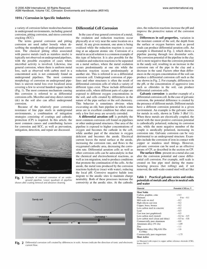
corrosion are used rather loosely when de-scribing the morphology of underground corro-sion. The classical pitting often associatedwith passive metals (such as stainless steels) istypically not observed on underground pipelines,with the possible exception of cases wheremicrobial activity is involved. Likewise, truegeneral corrosion, where there is uniform metalloss, such as observed with carbon steel in aconcentrated acid, is not commonly found onunderground pipelines. The most commonmorphology of corrosion on underground pipe-lines is uneven metal loss over localized areascovering a few to several hundred square inches(Fig. 1). The most common mechanism causingthis corrosion is referred to as differentialcorrosion cells. Microbes and stray direct current(dc) in the soil also can affect undergroundcorrosion.Because of the relatively poor corrosion
resistance of line pipe steels in undergroundenvironments, a combination of mitigationstrategies consisting of coatings and cathodicprotection (CP) is required. In this article, themost common causes and contributing factorsfor corrosion and SCC, as well as prevention,mitigation, detection, and repair are discussed.
Differential Cell Corrosion
In the case of true general corrosion of ametal,the oxidation and reduction reactions occurphysically at or very near the same location on ametal. At any given moment, one atom is beingoxidized while the reduction reaction is occur-ring at an adjacent atomic site. Corrosion of ametal in an acid solution is a common example ofthis type of behavior. It is also possible for theoxidation and reduction reactions to be separatedon a metal surface, where the metal oxidationoccurs predominantly at one site while thereduction reaction occurs predominantly atanother site. This is referred to as a differentialcorrosion cell. Underground corrosion of pipe-lines and other structures is often the result ofdifferential corrosion cells of which a variety ofdifferent types exist. These include differentialaeration cells, where different parts of a pipe areexposed to different oxygen concentrations inthe soil, and cells created by differences in thenature of the pipe surface or the soil chemistry.This behavior is sometimes obvious whenexcavating an old, bare pipeline in which someareas are in excellent condition but other areasonly a few feet away are severely corroded.A differential aeration cell is probably the
most common corrosion cell found on pipelinesor other underground structures. One area of thepipeline is exposed to higher concentrations ofoxygen and becomes the cathode in the cell,while another part of the structure is oxygendeficient and becomes the anode. Electricalcurrent leaves the metal surface at the anode,increasing the corrosion rate, and flows to theoxygenated cathodic area, decreasing the corro-sion rate. Differential aeration cells as well asother corrosion cells can be autocatalytic in thatthe chemical and electrochemical reactions, aswell as ion migration, tend to produce conditionsthat promote the continuation of the cells. At theanode, the metal ions produced by the corrosionreactions hydrolyze (react with water), reducingthe local pH. Corrosive negative halide ionsmigrate to the anodic sites to maintain chargeneutrality. Both of these processes increase thecorrosivity at the anodic sites. At the cathodic
sites, the reduction reactions increase the pH andimprove the protective nature of the corrosionfilms.Differences in soil properties, variation in
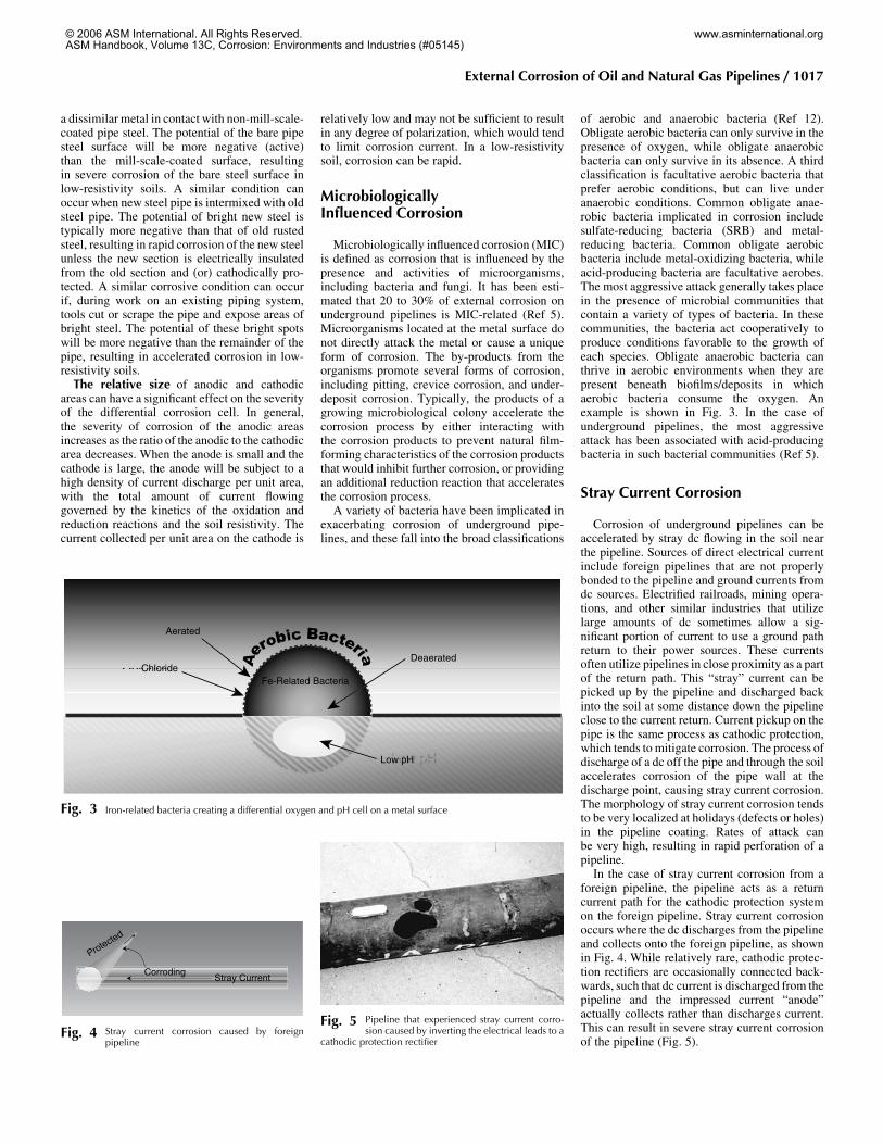
the moisture content of the soil, the depth fromthe surface or oxygen barriers such as pavedroads can produce differential aeration cells. Anexample is illustrated in Fig. 2, which shows apipeline passing through two dissimilar soils.The corrosion potential of the pipeline in the claysoil is more negative than the corrosion potentialin the sandy soil, resulting in an increase in thecorrosion rate of the pipe in the clay and adecrease in the sand. Factors other than differ-ences in the oxygen concentration of the soil canproduce a differential corrosion cell such as theone shown in Fig. 2. For example, differences inthe pH, or the concentration of aggressive ionssuch as chlorides in the soil, can producedifferential corrosion cells.Galvanic corrosion is another example of a
differential corrosion cell. In the case of galvaniccorrosion, the potential difference is created bythe presence of different metals. Different metalshave a different corrosion potential in a givenenvironment. An example is the galvanic seriesfor metals in soils, shown in Table 3 (Ref 11).When these metals are electrically coupled, themetal with the most positive corrosion potentialis cathodically polarized, reducing its corrosionrate, while the more negative member of thecouple is anodically polarized, increasing itscorrosion rate. Galvanic corrosion can be verydetrimental to an underground structure. Exam-ples include the corrosion of iron in contact withcopper or stainless steel fittings. However,galvanic corrosion can be used as an effectivemeans of CP, as described in the section on CP.The surface films present on a metal also can
alter the corrosion potential and cause differ-ential cell corrosion. For example, mill scale iscreated on line pipe steel during the manu-facturing process (hot rolling) and, if notremoved, the mill-scale-coated steel will act like
Sandy soil Clay soil
CorrodingProtected
e-1CorrodingProtected CorrodingProtected
e–1
Fig. 2 Differential corrosion cell created by differences in soils. Arrows indicate the direction of ionic and electroniccurrent flow.
Fig. 1 Example of external corrosion of an under-ground pipeline. Lower quadrant of pipeline
shown after coating removal and abrasive cleaning
Table 3 Practical galvanic series and redoxpotentials of metals and alloys in neutral soilsand water
Material Potential (CSE)(a), V
Most NobleCarbon, graphite, coke +0.3Platinum 0 to �0.1Mill scale on steel �0.2High-silicon cast iron �0.2Copper, brass, bronze �0.2Low-carbon steel in concrete �0.2Lead �0.5Cast iron (not graphitized) �0.5Low-carbon steel (rusted) �0.2 to �0.5Low-carbon steel (clean and shiny) �0.5 to �0.8Commercially pure aluminum �0.8Aluminum alloy (5% Zn) �1.05Zinc �1.1Magnesium alloy (Mg-6Al-3Zn-0.15Mn)
�1.6
Commercially pure magnesium �1.75Most Active
(a) Measured with respect to copper sulfate reference electrode (CSE).Source: Ref 11
1016 / Corrosion in Specific Industries
© 2006 ASM International. All Rights Reserved.ASM Handbook, Volume 13C, Corrosion: Environments and Industries (#05145)
www.asminternational.org
a dissimilar metal in contact with non-mill-scale-coated pipe steel. The potential of the bare pipesteel surface will be more negative (active)than the mill-scale-coated surface, resultingin severe corrosion of the bare steel surface inlow-resistivity soils. A similar condition canoccur when new steel pipe is intermixed with oldsteel pipe. The potential of bright new steel istypically more negative than that of old rustedsteel, resulting in rapid corrosion of the new steelunless the new section is electrically insulatedfrom the old section and (or) cathodically pro-tected. A similar corrosive condition can occurif, during work on an existing piping system,tools cut or scrape the pipe and expose areas ofbright steel. The potential of these bright spotswill be more negative than the remainder of thepipe, resulting in accelerated corrosion in low-resistivity soils.The relative size of anodic and cathodic
areas can have a significant effect on the severityof the differential corrosion cell. In general,the severity of corrosion of the anodic areasincreases as the ratio of the anodic to the cathodicarea decreases. When the anode is small and thecathode is large, the anode will be subject to ahigh density of current discharge per unit area,with the total amount of current flowinggoverned by the kinetics of the oxidation andreduction reactions and the soil resistivity. Thecurrent collected per unit area on the cathode is
relatively low and may not be sufficient to resultin any degree of polarization, which would tendto limit corrosion current. In a low-resistivitysoil, corrosion can be rapid.
MicrobiologicallyInfluenced Corrosion
Microbiologically influenced corrosion (MIC)is defined as corrosion that is influenced by thepresence and activities of microorganisms,including bacteria and fungi. It has been esti-mated that 20 to 30% of external corrosion onunderground pipelines is MIC-related (Ref 5).Microorganisms located at the metal surface donot directly attack the metal or cause a uniqueform of corrosion. The by-products from theorganisms promote several forms of corrosion,including pitting, crevice corrosion, and under-deposit corrosion. Typically, the products of agrowing microbiological colony accelerate thecorrosion process by either interacting withthe corrosion products to prevent natural film-forming characteristics of the corrosion productsthat would inhibit further corrosion, or providingan additional reduction reaction that acceleratesthe corrosion process.A variety of bacteria have been implicated in
exacerbating corrosion of underground pipe-lines, and these fall into the broad classifications
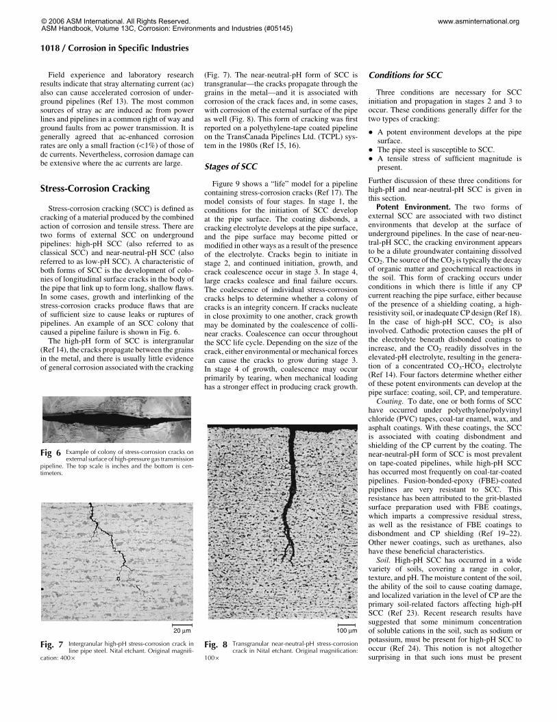
of aerobic and anaerobic bacteria (Ref 12).Obligate aerobic bacteria can only survive in thepresence of oxygen, while obligate anaerobicbacteria can only survive in its absence. A thirdclassification is facultative aerobic bacteria thatprefer aerobic conditions, but can live underanaerobic conditions. Common obligate anae-robic bacteria implicated in corrosion includesulfate-reducing bacteria (SRB) and metal-reducing bacteria. Common obligate aerobicbacteria include metal-oxidizing bacteria, whileacid-producing bacteria are facultative aerobes.The most aggressive attack generally takes placein the presence of microbial communities thatcontain a variety of types of bacteria. In thesecommunities, the bacteria act cooperatively toproduce conditions favorable to the growth ofeach species. Obligate anaerobic bacteria canthrive in aerobic environments when they arepresent beneath biofilms/deposits in whichaerobic bacteria consume the oxygen. Anexample is shown in Fig. 3. In the case ofunderground pipelines, the most aggressiveattack has been associated with acid-producingbacteria in such bacterial communities (Ref 5).
Stray Current Corrosion
Corrosion of underground pipelines can beaccelerated by stray dc flowing in the soil nearthe pipeline. Sources of direct electrical currentinclude foreign pipelines that are not properlybonded to the pipeline and ground currents fromdc sources. Electrified railroads, mining opera-tions, and other similar industries that utilizelarge amounts of dc sometimes allow a sig-nificant portion of current to use a ground pathreturn to their power sources. These currentsoften utilize pipelines in close proximity as a partof the return path. This “stray” current can bepicked up by the pipeline and discharged backinto the soil at some distance down the pipelineclose to the current return. Current pickup on thepipe is the same process as cathodic protection,which tends tomitigate corrosion. The process ofdischarge of a dc off the pipe and through the soilaccelerates corrosion of the pipe wall at thedischarge point, causing stray current corrosion.The morphology of stray current corrosion tendsto be very localized at holidays (defects or holes)in the pipeline coating. Rates of attack canbe very high, resulting in rapid perforation of apipeline.In the case of stray current corrosion from a
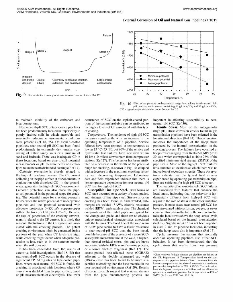
foreign pipeline, the pipeline acts as a returncurrent path for the cathodic protection systemon the foreign pipeline. Stray current corrosionoccurs where the dc discharges from the pipelineand collects onto the foreign pipeline, as shownin Fig. 4. While relatively rare, cathodic protec-tion rectifiers are occasionally connected back-wards, such that dc current is discharged from thepipeline and the impressed current “anode”actually collects rather than discharges current.This can result in severe stray current corrosionof the pipeline (Fig. 5).
Fig. 5 Pipeline that experienced stray current corro-sion caused by inverting the electrical leads to a
cathodic protection rectifier
Corroding
Protected
Stray Current
Fig. 4 Stray current corrosion caused by foreignpipeline
Fe-Related Bacteria
Aerated
ChlorideDeaerated
Low pH
Fe-Related Bacteria
Aerated
ChlorideDeaerated
Low pH
Fig. 3 Iron-related bacteria creating a differential oxygen and pH cell on a metal surface
External Corrosion of Oil and Natural Gas Pipelines / 1017
© 2006 ASM International. All Rights Reserved.ASM Handbook, Volume 13C, Corrosion: Environments and Industries (#05145)
www.asminternational.org
Field experience and laboratory researchresults indicate that stray alternating current (ac)also can cause accelerated corrosion of under-ground pipelines (Ref 13). The most commonsources of stray ac are induced ac from powerlines and pipelines in a common right of way andground faults from ac power transmission. It isgenerally agreed that ac-enhanced corrosionrates are only a small fraction (51%) of those ofdc currents. Nevertheless, corrosion damage canbe extensive where the ac currents are large.
Stress-Corrosion Cracking
Stress-corrosion cracking (SCC) is defined ascracking of a material produced by the combinedaction of corrosion and tensile stress. There aretwo forms of external SCC on undergroundpipelines: high-pH SCC (also referred to asclassical SCC) and near-neutral-pH SCC (alsoreferred to as low-pH SCC). A characteristic ofboth forms of SCC is the development of colo-nies of longitudinal surface cracks in the body ofthe pipe that link up to form long, shallow flaws.In some cases, growth and interlinking of thestress-corrosion cracks produce flaws that areof sufficient size to cause leaks or ruptures ofpipelines. An example of an SCC colony thatcaused a pipeline failure is shown in Fig. 6.The high-pH form of SCC is intergranular
(Ref 14), the cracks propagate between the grainsin the metal, and there is usually little evidenceof general corrosion associated with the cracking
(Fig. 7). The near-neutral-pH form of SCC istransgranular—the cracks propagate through thegrains in the metal—and it is associated withcorrosion of the crack faces and, in some cases,with corrosion of the external surface of the pipeas well (Fig. 8). This form of cracking was firstreported on a polyethylene-tape coated pipelineon the TransCanada Pipelines Ltd. (TCPL) sys-tem in the 1980s (Ref 15, 16).
Stages of SCC
Figure 9 shows a “life” model for a pipelinecontaining stress-corrosion cracks (Ref 17). Themodel consists of four stages. In stage 1, theconditions for the initiation of SCC developat the pipe surface. The coating disbonds, acracking electrolyte develops at the pipe surface,and the pipe surface may become pitted ormodified in other ways as a result of the presenceof the electrolyte. Cracks begin to initiate instage 2, and continued initiation, growth, andcrack coalescence occur in stage 3. In stage 4,large cracks coalesce and final failure occurs.The coalescence of individual stress-corrosioncracks helps to determine whether a colony ofcracks is an integrity concern. If cracks nucleatein close proximity to one another, crack growthmay be dominated by the coalescence of colli-near cracks. Coalescence can occur throughoutthe SCC life cycle. Depending on the size of thecrack, either environmental or mechanical forcescan cause the cracks to grow during stage 3.In stage 4 of growth, coalescence may occurprimarily by tearing, when mechanical loadinghas a stronger effect in producing crack growth.
Conditions for SCC
Three conditions are necessary for SCCinitiation and propagation in stages 2 and 3 tooccur. These conditions generally differ for thetwo types of cracking:
� A potent environment develops at the pipesurface.
� The pipe steel is susceptible to SCC.� A tensile stress of sufficient magnitude is
present.
Further discussion of these three conditions forhigh-pH and near-neutral-pH SCC is given inthis section.Potent Environment. The two forms of
external SCC are associated with two distinctenvironments that develop at the surface ofunderground pipelines. In the case of near-neu-tral-pH SCC, the cracking environment appearsto be a dilute groundwater containing dissolvedCO2. The source of the CO2 is typically the decayof organic matter and geochemical reactions inthe soil. This form of cracking occurs underconditions in which there is little if any CPcurrent reaching the pipe surface, either becauseof the presence of a shielding coating, a high-resistivity soil, or inadequate CP design (Ref 18).In the case of high-pH SCC, CO2 is alsoinvolved. Cathodic protection causes the pH ofthe electrolyte beneath disbonded coatings toincrease, and the CO2 readily dissolves in theelevated-pH electrolyte, resulting in the genera-tion of a concentrated CO3-HCO3 electrolyte(Ref 14). Four factors determine whether eitherof these potent environments can develop at thepipe surface: coating, soil, CP, and temperature.Coating. To date, one or both forms of SCC
have occurred under polyethylene/polyvinylchloride (PVC) tapes, coal-tar enamel, wax, andasphalt coatings. With these coatings, the SCCis associated with coating disbondment andshielding of the CP current by the coating. Thenear-neutral-pH form of SCC is most prevalenton tape-coated pipelines, while high-pH SCChas occurred most frequently on coal-tar-coatedpipelines. Fusion-bonded-epoxy (FBE)-coatedpipelines are very resistant to SCC. Thisresistance has been attributed to the grit-blastedsurface preparation used with FBE coatings,which imparts a compressive residual stress,as well as the resistance of FBE coatings todisbondment and CP shielding (Ref 19–22).Other newer coatings, such as urethanes, alsohave these beneficial characteristics.Soil. High-pH SCC has occurred in a wide
variety of soils, covering a range in color,texture, and pH. The moisture content of the soil,the ability of the soil to cause coating damage,and localized variation in the level of CP are theprimary soil-related factors affecting high-pHSCC (Ref 23). Recent research results havesuggested that some minimum concentrationof soluble cations in the soil, such as sodium orpotassium, must be present for high-pH SCC tooccur (Ref 24). This notion is not altogethersurprising in that such ions must be present
Fig 6 Example of colony of stress-corrosion cracks onexternal surface of high-pressure gas transmission
pipeline. The top scale is inches and the bottom is cen-timeters.
20 µm
Fig. 7 Intergranular high-pH stress-corrosion crack inline pipe steel. Nital etchant. Original magnifi-
cation: 400·
100 µm
Fig. 8 Transgranular near-neutral-pH stress-corrosioncrack in Nital etchant. Original magnification:
100·
1018 / Corrosion in Specific Industries
© 2006 ASM International. All Rights Reserved.ASM Handbook, Volume 13C, Corrosion: Environments and Industries (#05145)
www.asminternational.org
to maintain solubility of the carbonate andbicarbonate ions.Near-neutral-pH SCC of tape-coated pipelines
has been predominantly located in imperfectly topoorly drained soils in which anaerobic andseasonally reducing environmental conditionswere present (Ref 18, 25). On asphalt-coatedpipelines, near-neutral-pH SCC has been foundpredominantly in extremely dry terrains con-sisting of either sandy soils or a mixture ofsand and bedrock. There was inadequate CP inthese locations, based on pipe-to-soil potentialmeasurements or pH measurements of electro-lytes found beneath disbonded coatings (Ref 17).Cathodic protection is closely related to
the high-pH cracking process. The CP currentcollecting on the pipe surface at disbondments, inconjunction with dissolved CO2 in the ground-water, generates the high-pH SCC environment.Cathodic protection can also place the pipe-to-soil potential in the potential range for crack-ing. The potential range for cracking generallylies between the native potential of undergroundpipelines and the potential associated withadequate protection (�850 mV copper/coppersulfate electrode, or CSE) (Ref 26–28). Becausethe rate of generation of the cracking environ-ment is related to the CP current, it is likely thatseasonal fluctuations in the CP system are asso-ciated with the cracking process. The potentcracking environment might be generated duringportions of the year when CP levels are high,while cracking might occur when adequate pro-tection is lost, such as in the summer monthswhen the soil dries out.It has been concluded from the results of
extensive field investigations (Ref 18, 25) thatnear-neutral-pH SCC occurs in the absence ofsignificant CP. At dig sites on tape-coated pipe-lines, where near-neutral-pH SCC is found, thecracking is associated with locations where CPcurrent was shielded from the pipe surface, basedon pH measurements of electrolytes. The lower
occurrence of SCC on the asphalt-coated por-tions of the system probably can be attributed tothe higher levels of CP associated with this typeof coating.Temperature. The incidence of high-pH SCC
increases significantly with an increase in theoperating temperature of a pipeline. Servicefailures have been reported at temperatures aslow as 13 �C (55 �F), but 90% of the service andhydrostatic test failures have occurred within16 km (10 miles) downstream from compressorstations (Ref 27). This behavior has been attrib-uted to a decrease in the width of the potentialrange for cracking, as shown in Fig. 10, coupledwith a decrease in the maximum cracking veloc-ity with decreasing temperature. Laboratorydata and field experience indicate that there isless temperature dependence for near-neutral-pHSCC than for high-pH SCC.Susceptible Line Pipe Steel. Both forms of
SCC have occurred on a variety of sizes, grades,and vintages of line pipe steel. Stress-corrosioncracking has been found in flash welded, sub-merged arc welded (SAW), electric resistancewelded (ERW), and seamless pipe. The chemicalcompositions of the failed pipes are typical forthe vintage and grade, and there are no obviousunique metallurgical characteristics associatedwith the failures. The bond line of the weld seamof ERW pipe seems to have a lower resistanceto near-neutral-pH SCC than the base metal,possibly because of the presence of a more SCC-susceptible microstructure at the weld, a higher-than-normal residual stress, pits and arc burnsassociatedwith the ERWmanufacturing process,or a lower fracture toughness (Ref 17). Thecoarse-grained heat-affected zone (CGHAZ)adjacent to the double submerged arc weld(DSAW) also has been found to be more sus-ceptible to cracking than the base material in thenear-neutral-pH environment (Ref 29). Resultsof recent research suggest that residual stressesfrom the pipe manufacturing process are
important in affecting susceptibility to near-neutral-pH SCC (Ref 30).Tensile Stress. Most of the intergranular
(high-pH) stress-corrosion cracks found in gastransmission pipelines have been oriented in thelongitudinal direction (Ref 14). This orientationindicates the importance of the hoop stressproduced by the internal pressurization on thecracking process. The failures have occurred athoop stresses ranging from160 to 270 MPa (23 to39 ksi), which corresponded to 46 to 76% of thespecified minimum yield strength (SMYS) of thepipe steels. Most of the high-pH SCC failureshave initiated at locations at which there was noindication of secondary stresses. These observa-tions indicate that the typical field stressesexperienced by operating gas transmission pipe-lines are sufficient for high-pH SCC to occur.The majority of near-neutral-pH SCC failures
are associated with features that enhance thelocal stress, indicating that the behavior is fun-damentally different from high-pH SCC withregard to the role of stress in the crack initiationprocess. In most cases, near-neutral pH SCC hasbeen associated with corrosion, gouges, or stressconcentrations from the toe of the weld seam thatraise the local stress above the hoop-stress levelscalculated based on the internal pressurization(Ref 17). Significant SCC has not been reportedin class 2 and 3* pipeline locations, indicatingthat the hoop stress also is important (Ref 17).Cyclic pressure fluctuations that normally
occur on operating pipelines also affect SCCbehavior. It has been demonstrated that thecyclic stress that results from these pressure
Stage 1 Stage 2 Stage 3
Time
Cra
ck g
row
th r
ate
Stage 4
Large crackscoalescence
Growth by continuous initiation,extension, and coalescence
Cracksinitiate
Initiationconditionsdevelop
Failure
Fig. 9 Life model for a colony of stress-corrosion cracks. Source: Ref 17
–850
–800
–750
–700
–650
–600
20 30 40 50 60 70 80
Pot
entia
l, m
V (
CS
E)
Temperature, °C
Minimum potentialMaximum potentialAverage potential
Fig. 10 Effect of temperature on the potential range for cracking in a simulated high-pH cracking environment containing 12 g/L Na2CO3 and 37 g/L NaHCO3.
CSE, copper/copper sulfate electrode. Source: Ref 28
*Class locations for high-pressure gas pipelines are defined bythe US. Department of Transportation based on the con-sequences of a pipeline failure. Class 1 locations have thelowest consequence and are allowed to operate at a maximumpressure that is equivalent to 72% of SMYS. Class 4 locationshave the highest consequence of failure and are allowed tooperate at a maximum pressure that is equivalent to 40% ofSMYS (Reference CFR Part 192.111).
External Corrosion of Oil and Natural Gas Pipelines / 1019
© 2006 ASM International. All Rights Reserved.ASM Handbook, Volume 13C, Corrosion: Environments and Industries (#05145)
www.asminternational.org
fluctuations reduce the threshold stress forinitiation of high-pH SCC (Ref 31) and increasethe rate of propagation of near-neutral-pH stress-corrosion cracks (Ref 32).
Prevention and Mitigation ofCorrosion and SCC
The most effective method to prevent corro-sion or SCC on new pipelines is to use high-performance coatings, applied to a surfaceabrasive blast cleaned to awhite (Ref 33) or near-white (Ref 34) metal surface finish, in conjunc-tion with effective CP. An intact coating thatprevents contact of electrolyte with the steelsurface will prevent external corrosion or SCC.The surface abrasive blast cleaning promotesgood coating adhesion. A high-quality abrasiveblast cleaning also will impart compressiveresidual stresses in the pipe surface that improveSCC resistance.All coatings contain some defects or holes,
referred to as holidays, that expose the barepipeline steel to the underground environment.The function of the CP system is to protect thesebare areas from corrosion.Methods of preventing corrosion and SCC on
existing pipelines include minimizing the oper-ating temperature and controlling the CP levelsto values more negative than �850 mV CSE.Minimizing pressure fluctuations on operatingpipelines also is effective in preventing SCCinitiation. A more detailed discussion ofcoatings and cathodic protection is given in thissection.
Coatings
Inadequate coating performance is a majorcontributing factor in the corrosion and SCCsusceptibility of an underground pipeline. Thefunction and desired characteristics of a dielec-tric-type pipeline coating are covered in NACERP-0169 (Ref 35). This specification statesthat the function of such coatings is to controlcorrosion by isolating the external surface of theunderground or submerged piping from theenvironment, to reduce CP requirements, and toimprove (protective) current distribution. Coat-ings must be properly selected and applied, andthe coated piping must be carefully installed tofulfill these functions. The desired characteristicsof the coatings include:
� Effective electrical insulation� Effective moisture barrier� Good adhesion to the pipe surface� Applicable by a method that will not ad-
versely affect the properties of the pipe� Applicable with a minimum of defects� Ability to resist the development of holidays
with time� Ability to resist damage during handling,
storage, and installation� Ability to maintain substantially constant
resistivity with time
� Resistance to disbonding� Resistance to chemical degradation� Ease of repair� Retention of physical characteristics� Nontoxic to environment� Resistance to changes and deterioration dur-
ing above-ground storage and long-distancetransportation
Descriptions of common coatings used onunderground pipelines follow.Bituminous enamels are formulated from
coal-tar pitches or petroleum asphalts and havebeen widely used as protective coatings for morethan 65 years. Coal-tar and asphalt enamels areavailable in summer or winter grades. Theseenamels are the corrosion coating; they arecombined with various combinations of fiber-glass and/or felt to obtain mechanical strengthfor handling. The enamel coatings have been theworkhorse coatings of the industry, and whenproperly selected and applied, they can provideefficient long-term corrosion protection.Enamel systems can be designed for installa-
tion and use within an operating temperaturerange of �1 to 82 �C (30 to 180 �F). Whentemperatures fall below 4.4 �C (40 �F), addedprecautions should be taken to prevent crackingand disbonding of the coating during fieldinstallation. Enamels are affected by ultravioletrays and should be protected by kraft paper orwhitewash. Enamels are also affected byhydrocarbons, and the use of a barrier coat isrecommended when known contaminationexists. Bituminous enamel coatings are availablefor all sizes of pipe.In recent years, the use of enamels has de-
clined for these reasons:
� Reduced number of suppliers� Restrictive environmental and health stan-
dards from the Occupational Safety andHealth Administration, the EnvironmentalProtection Agency, and the Food and DrugAdministration
� Increased acceptance of other coating types� Alternative use of coating raw materials as
fuels
Asphalt mastic pipe coating is a dense mix-ture of sand, crushed limestone, and fiber boundtogether with a select air-blown asphalt. Thesematerials are proportioned to secure a maximumdensity of approximately 2.1 g/cm3 (132 lb/ft3).This mastic material is available with varioustypes of asphalt. Selection is based on operatingtemperature and climatic conditions to obtainmaximum flexibility and operating character-istics. This coating is a thick (12.7 to 16 mm, or1/2 to 5/8 in.) extruded mastic that results in aseamless corrosion coating. Extruded asphaltmastic pipe coating has been in use for more than50 years.Asphalt mastic systems can be designed for
installation and use within an operating range of4.4 to 88 �C (40 to 190 �F). Precautionarymeasures should be taken when handling asphaltmastics in freezing temperatures. Whitewash is
used to protect it from ultraviolet rays, and thisshould be maintained when in storage. Thissystem is not intended for use above ground or inhydrocarbon-contaminated soils.Liquid Epoxies and Phenolics. Many dif-
ferent liquid systems are available that cure byheat and/or chemical reaction. Some are solventtypes, and others are 100% solids. These systemsare primarily used on larger-diameter pipewhen conventional systems may not be availableor when they may offer better resistance tooperation temperatures in the 95 �C (200 �F)range.Generally, epoxies have an amine or a poly-
amide curing agent and require a near-whiteblast-cleaned surface (NACE No. 2 or SSPCSP10). Coal-tar epoxies have coal-tar pitchadded to the epoxy resin. A coal-tar epoxy curedwith a low-molecular-weight amine is especiallyresistant to an alkaline environment, such as thatwhich occurs on a cathodically protected struc-ture. Some coal-tar epoxies become brittle whenexposed to sunlight.Extruded plastic coatings fall into two
categories based on the method of extrusion,with additional variations resulting from theselection of adhesive. The two methods ofextrusion are the crosshead or circular die, andthe side extrusion or T-shaped die. The four typesof adhesives are asphalt-rubber blend, poly-ethylene copolymer, butyl rubber adhesive, andpolyolefin rubber blend.To date, of the polyolefins available, poly-
ethylene has found the widest use, with poly-propylene being used on a limited basis for itshigher operating temperature. Each type or var-iation of adhesive and method of extrusion offersdifferent characteristics based on the degree ofimportance to the user of certain measurableproperties.Fusion-bonded epoxy (FBE) coatings are
heat-activated, chemically cured coating sys-tems. The epoxy coating is furnished in pow-dered form and, with the exception of the weldedfield joints, is plant applied to preheated pipe,special sections, connections, and fittings usingfluid-bed, air spray, or electrostatic spraymethods.Fusion-bonded epoxy coatings were intro-
duced in 1959 and were first used as an exteriorpipe coating in 1961 and currently are the coat-ings most commonly used for new installationsof large diameter pipelines (Ref 36). Thesecoatings are applied to preheated pipe surfaces at218 to 244 �C (425 to 475 �F). Some systemsmay require a primer system, and some requirepostheating for complete cure. A NACE No. 2(SSPC SP10) near-white blast-cleaned surface isrequired. The coating is applied to a minimumthickness of 0.3 mm (12 mils); in some appli-cations, coating thicknesses range to 0.64 mm(25 mils), with the restriction not to bend pipecoated with a film thickness greater than 0.4 mm(16 mils). The FBE coatings exhibit goodmechanical and physical properties and arethe most resistant to hydrocarbons, acids, andalkalies.
1020 / Corrosion in Specific Industries
© 2006 ASM International. All Rights Reserved.ASM Handbook, Volume 13C, Corrosion: Environments and Industries (#05145)
www.asminternational.org
A primary advantage of the FBE pipe coatingsis that they cannot hide apparent surface defects;therefore, the steel surface can be inspected afterit is coated. The number of holidays that occuris a function of the surface condition and thethickness of the coating specified. Increasing thethickness minimizes this problem, and theexcellent resistance to the electrically induceddisbondment of these coatings has resulted intheir frequent use as pipeline coatings.Tape. Field and mill-applied tape systems
have been in use for more than 30 years onpipelines. For normal construction conditions,prefabricated cold-applied tapes are appliedas a three-layer system consisting of a primer,corrosion-preventive tape (inner layer), and amechanically protective tape (outer layer). Thefunction of the primer is to provide a bondingmedium between the pipe surface and the adhe-sive or sealant on the inner layer. The inner-layertape consists of a plastic backing and an adhe-sive. This layer is the corrosion-protective coat-ing; therefore, it must provide a high electricalresistivity, low moisture absorption and perme-ability, and an effective bond to the primed steelsurface. The outer-layer tape consists of a plasticfilm and an adhesive composed of the same typesof materials used in the inner tape or materialsthat are compatible with the inner-layer tape. Thepurpose of the outer-layer tape is to providemechanical protection to the inner-layer tape andto be resistant to the elements during outdoorstorage. The outer-layer tape is usually a mini-mum of 0.64 mm (25 mils) thick.The cold-applied multilayer tape systems are
designed for plant coating operations and resultin a uniform, reproducible, holiday-free coatingover the entire length of any size pipe. Themultiple-layer system allows the coating thick-ness to be custom designed to meet specificenvironmental conditions. These systems havebeen engineered to withstand normal handling,outdoor weathering, storage, and shipping con-ditions.Three-Layer Polyolefin. The three-layer
polyolefin pipeline coating was developed in the1990s as a way to combine the excellent adhe-sion of FBE with the damage resistance ofextruded polyethylene and tape wraps. Thesesystems consist of an FEB primer, an inter-mediate copolymer layer, and a topcoat con-sisting of either polyethylene or polypropylene.The function of the intermediate copolymer isto bond the FBE primer with the polyolefintopcoat.Variations in these three-layer systems exist,
most notably the use of either polyethylene orpolypropylene for the topcoat. Polypropyleneoffers a higher temperature resistance but ismore costly, both as a raw material and becausehigher temperatures are required for application.Most topcoats are side extruded similar toextruded polyethylene coatings, although at leastone product uses flame-spray polyolefin for atopcoat. Another variation in the three-layersystems is the thickness of the FBE primer layer.Early generations of this product utilized a
50–75 mm (2–3 mil) primer which often provedto be inadequate to achieve the desired per-formance. More recent three-layer systemsutilize a 200–300 mm (8–12 mil) primer as astandard thickness.Wax coatings have been in use for more than
50 years and are still employed on a limitedbasis. Microcrystalline wax coatings are usuallyused with a protective overwrap. The wax servesto waterproof the pipe, and the wrapper protectsthe wax coating from contact with the soil andaffords some mechanical protection. The mostprevalent use of wax coatings is the over-the-ditch application with a combination machinethat cleans, coats, wraps, and lowers into theditch in one operation.
Special-Use Coatings
Polyurethane Thermal Insulation. Efficientpipeline insulation has grown increasinglyimportant as a means of operating hot and coldservice pipelines. This is a system for controllingheat transfer in above- or belowground andmarine pipelines. Polyurethane insulation isgenerally used in conjunction with a corrosioncoating, but if the proper moisture vapor barrieris used over the polyurethane foam, effectivecorrosion protection is attained.Concrete. Mortar linings and coatings have
the longest history of use in protecting steel orwrought iron from corrosion. The alkalinity ofthe concrete promotes the formation of a pro-tective iron oxide (passive) film on the steel. Thisprotective passive film can be compromised inunderground applications by permeation ofchlorides into the coating. Typically, externalapplication is usually employed over a corro-sion-resistant coating for armor protection andnegative buoyancy in marine environments.Metallic (Galvanic) Coatings. Pipe coated
with a galvanic coating, such as zinc (galva-nizing) or cadmium, should not be utilized indirect burial service. Such metallic coatings areintended for the mitigation of atmospheric-typecorrosion activity on the substrate steel.
Evaluating Coatings
As described previously, the different types ofcoatings used on underground pipelines havedifferent strengths and weaknesses. When firstinstalled, most pipeline coatings are effective inmeeting their required function: isolate theexternal surface of an underground pipeline fromthe environment, reduce the CP current require-ments, and improve the CP current distribution.On the other hand, coatings vary significantly intheir long-term performance. Ultimately, theeffectiveness of a coating system in preventingcorrosion is related to two primary factors: (a)the resistance of a coating to degradation overtime and (b) the ability of the coating to conductCP current should the coating fail (minimizeshielding). For SCC resistance, these factors as
well as the type of surface preparation used withthe coating are important.The ability of a coating to resist degradation is
a primary performance property of coatings andaffects all forms of external pipeline corrosion.The second factor, the ability of a coating to passCP current, should it fail, is the inverse ofshielding of the CP current beneath a disbondedcoating. Corrosion or SCC can occur beneath adisbonded coating that shields CP current eventhough the pipeline is apparently effectivelyprotected, based on ground-level measurements.
Surface Preparation
The nature of the surface preparation isprobably more important in mitigating SCCthan other forms of corrosion. Historically, theprimary purposes of the surface preparation havebeen to clean the surface and create an anchorpattern to promote good adhesion of the coatingto the pipe surface. The surface preparationrequirements for different coating types vary.For example, bituminous coatings have goodadhesion properties on commercial blast-cleanedsurfaces (NACE No. 3/SSPC-SP 6) or even onwire-brushed surfaces, whereas fusion-bondedepoxy (FBE) coatings require a white (NACENo. 1/SSPC-SP 5) or near-white (NACE No. 2/SSPC-SP 10) grit-blasted surface finish forproper adhesion. Laboratory research and fieldexperience have demonstrated that grit-blastedsurfaces are generally more resistant to SCCinitiation thanwire-brushedmill-scaled surfaces,primarily because grit blasting imparts a com-pressive residual stress in the pipe surface (Ref20, 21, 36). A white or near-white surface finishwas found to be required to impart SCC resis-tance, whereas commercially blasted surfaceswere found to be more susceptible to SCC thanwire-brushed milled scaled surfaces.The Canadian Energy Pipeline Association
(CEPA) member companies have recommendedthat the following coatings be considered fornew construction based on SCC performance(Ref 37):
� Fusion-bonded epoxy� Liquid epoxy� Urethane� Extruded polyethylene� Multilayer or composite coatings
Fusion-bonded epoxies, liquid epoxies, andurethane coatings meet all three requirements ofan effective coating: (a) they are resistant todegradation over time, (b) they conduct CPcurrent should they fail, and (c) they are typicallyapplied over a white or near-white grit-blastedsurface. Extruded polyethylene coatings meetrequirements 1 and 3, but will shield CP currentshould disbondment occur. Furthermore, thetype of coating used on the field joints frequentlylimits the performance of extruded polyethylene-coated pipelines. Multilayer or composite coat-ings typically consist of an FBE inner layer and apolyolefin outer layer with an adhesive between
External Corrosion of Oil and Natural Gas Pipelines / 1021
© 2006 ASM International. All Rights Reserved.ASM Handbook, Volume 13C, Corrosion: Environments and Industries (#05145)
www.asminternational.org
the two layers. These new coatings are promisingfrom the standpoint of resistance to disbond-ment, mechanical damage, and soil stresses, butthe polyolefin outer layer will shield CP currentshould disbondment occur. Additional fieldexperience is needed to establish the perfor-mance of these coatings.Tape coatings and bituminous coatings have
been shown to be more susceptible to SCC thanthe aforementioned coatings and should be usedonly with careful consideration of all of thefactors affecting SCC. Regardless of the coatingselected, the pipe surface should be prepared to awhite (NACE No. 1/SSPC-SP 5) or near-white(NACE No. 2/SSPC-SP 10) finish to aid incoating adhesion and impart sufficient residualcompressive stresses to prevent SCC initiation.A lower-quality commercial blast (NACE No. 3/SSPC-SP 6) should not be used under anycircumstances.
Cathodic Protection
External corrosion and SCC are electro-chemical phenomena and, therefore, can beprevented or mitigated by altering the electro-chemical condition of the corroding interface.Altering the electrochemical nature of the cor-roding surface is relatively simple and is doneby altering the electrical potential field aroundthe pipe. By applying a negative potential andmaking the pipe a cathode, the rate of corrosion(oxidation) is reduced (corrosion is prevented ormitigated) and the reduction process is acceler-ated. This means of mitigating (or preventing)corrosion, cathodic protection, also alters theenvironment at the pipe surface, which furtherenhances corrosion control. The pH of anyelectrolyte at the pipe surface is increased, theoxygen concentration is reduced, and deleteriousanions, such as chloride, migrate away from thepipe surface.Types of CP. There are two primary types
of CP systems: sacrificial anode (galvanic anode)CP and impressed-current CP. Sacrificial anodeCP utilizes an anode material that is electro-
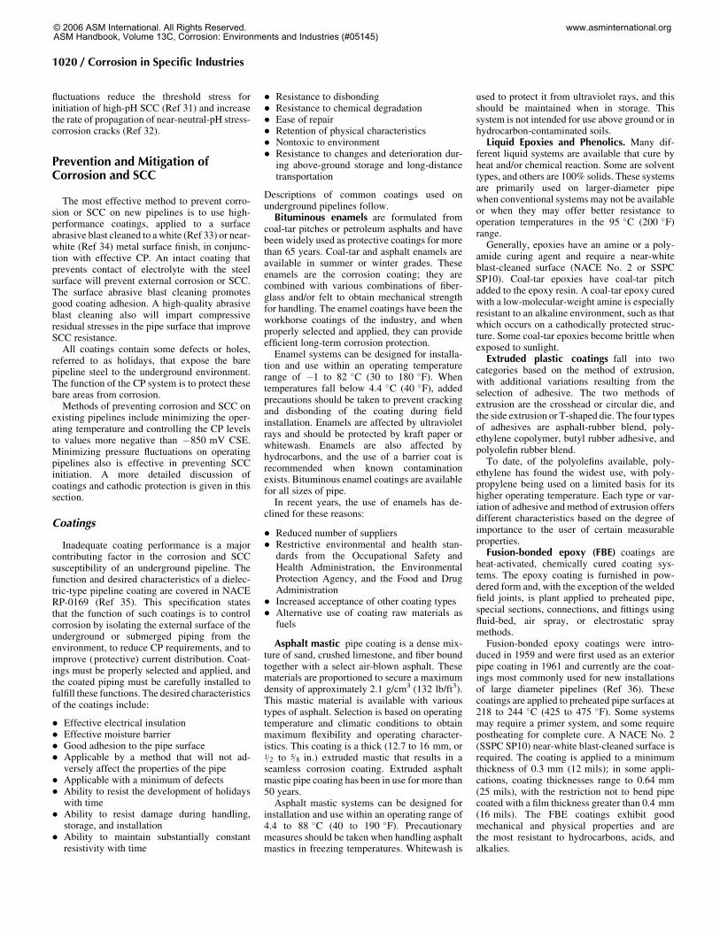
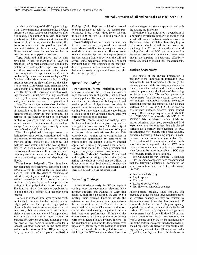
negative to the pipe steel. When connected to thepipe, the pipe becomes the cathode in the circuitand corrosion is mitigated. Typical sacrificialanode materials for underground pipelines arezinc and magnesium. Impressed-current CP uti-lizes an outside power supply (rectifier) to con-trol the voltage between the pipe and an anode(cast iron, graphite, platinum clad, mixed metaloxide, etc.) in such a manner that the pipebecomes the cathode in the circuit and corrosionis mitigated. Schematics of these two types of CPsystems are shown in Fig. 11 and 12.Cathodic protection is most often used in
conjunction with a coating. There are alwaysflaws in the coating due to application incon-sistencies, construction damage, or the combi-nation of natural aging and soil stresses. If leftunprotected, the pipeline will undergo corrosionor SCC at these coating flaws (holidays). Oftenthe rate of attack through the wall is much higherat the holiday than the general attack of a baresteel surface. The use of a coating greatly redu-ces the total amount of current required toachieve protection of the pipeline system;therefore, CP and external coatings are utilizedtogether wherever possible.Cathodic protection can be used to control all
types of corrosion previously discussed (general,stray current, MIC, and SCC). Sometimes it isdifficult to determine the level of CP necessary tomitigate the different corrosion mechanisms andto identify which type of corrosion is present.Stress-corrosion cracking presents additionalproblems. First, the high-pH form of SCC is onlyfound on pipelines protected with CP. The pro-ducts that result from cathodic reactions occur-ring on the pipe surface during CP in conjunctionwith soil chemistry produce the environmentnecessary for high-pH SCC. Since high-pH SCCpropagates only in a very limited potential range,maintaining the potential of the pipe surfaceoutside of this range by proper CP control willprevent growth of the high-pH SCC cracks. Inaddition, it has been established that proper CPcontrol can inhibit the growth of near-neutralSCC cracks.
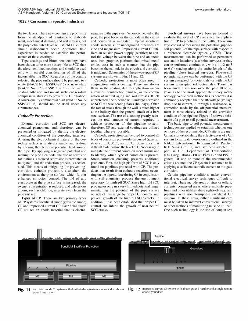
Electrical surveys have been performed toevaluate the level of CP ever since the applica-tion of CP to pipelines in the 1940s. These sur-veys consist of measuring the potential (pipe-to-soil potential) of the pipe surface with respect toa reference electrode (typically CSE). Thesemeasurements can be performed at permanenttest station locations (test point surveys), or theycan be performed continuously with a 1 to 2 m (3to 6 ft) spacing along the entire length of thepipeline (close interval surveys). Pipe-to-soilpotential surveys can be performed with the CPsystem energized (on-potentials) or with the CPsystem interrupted (off-potentials). There hasbeen much discussion over the past 10 to 20years as to the most appropriate survey meth-odology. While each method has its benefits, it iscommonly accepted that the IR-voltage (voltagedrop due to current, I, through a resistance, R)correction made by the off-potential measure-ment is most closely related to the corrosioncondition of the pipeline. Figure 13 shows a sche-matic of a pipe-to-soil potential measurement.The basic pipe-to-soil potential measurement
techniques are applied to establish whether oneor more of the recommended CP criteria are met.Criteria for establishing the effectiveness of a CPsystem to mitigate corrosion are outlined in theNACE International Recommended PracticeRP0169-96 (Ref 35) and have been adopted, inpart, in U.S. Department of Transportation(DOT) regulations CFR 49, Parts 192 and 195. Ingeneral, if one or more of the recommendedcriteria are met, the CP system is assumed to beapplying a sufficient cathodic current to mitigatecorrosion.Certain pipeline conditions make conven-
tional electrical survey techniques difficult tointerpret. These include areas of stray or telluriccurrents, congested areas where multiple pipe-lines and other utilities share rights-of-way, andpipelines with noninterruptible sacrificial CPsystems. In these areas, either significant caremust be taken to interpret conventional surveysor other methods of monitoring must be utilized.One such technology is the use of coupon test
Mg MgMgMg MgMg
Pipeline
Beneficial Sacrificial Protection
Fig. 11 Sacrificial anode CP system with distributed magnesium anodes and an above-ground test station
Pipeline
Rectifier
Goundbed
Fig. 12 Impressed current CP system with above-ground rectifier and a single remoteanode groundbed
1022 / Corrosion in Specific Industries
© 2006 ASM International. All Rights Reserved.ASM Handbook, Volume 13C, Corrosion: Environments and Industries (#05145)
www.asminternational.org
stations. The coupon test stations permit accuratepotential measurements for a test specimen(coupon) that simulates a holiday on the pipesurface.
Detection of Corrosion and SCC
On existing pipelines, there are three methodsto detect corrosion and SCC—hydrostaticretesting, field investigation programs (directassessment), and in-line inspection.Hydrostatic Testing. Hydrostatic retesting
involves pressure testing the pipeline with waterat a pressure that is higher than the operatingpressure, typically 125% of the maximum oper-ating pressure (MOP) of the pipeline. This is themost commonmethod to ensure the integrity of apipeline and establish a safe operating pressure,regardless of the types of flaws present in thepipeline. Any flaws that are larger than a criticalsize at the hydrostatic retest pressure areremoved from the pipeline. However, subcriticalflaws remain in the pipeline after a hydrostaticretest. If the defects are growing with time,as might be the case with corrosion or SCC,the pipeline is generally periodically retestedto ensure integrity. Hydrostatic retesting isexpensive and creates problems associated withthe acquisition, treatment, and disposal of thewater, especially for pipelines carrying liquidproducts.Direct Assessment. As a part of condition-
monitoring programs, pipeline companies com-monly use field investigation (direct assessment)programs. The overall condition of the coatingsand pipelines is assessed, and it is determinedwhether corrosion or SCC is present on the sys-tem. Models are sometimes developed to predictthe likelihood of the presence and severity ofcorrosion or cracking. This information is thenused to prioritize the system for direct exam-ination, hydrostatic testing, in-line inspection,recoating, or pipe replacement. Dig programsand the associated models are not generallyconsidered as a replacement for hydrostatictesting as a means to ensure the integrity of apipeline. See the article “External CorrosionDirect Assessment Integrated with IntegrityManagement” in this Volume.
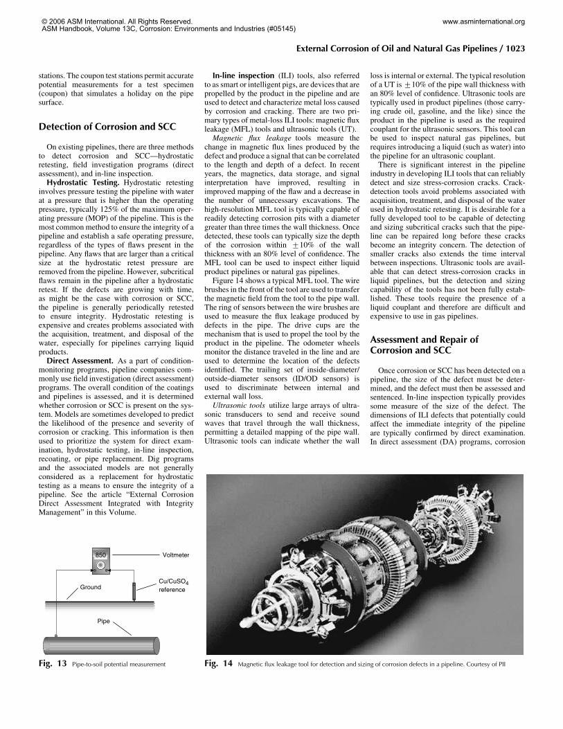
In-line inspection (ILI) tools, also referredto as smart or intelligent pigs, are devices that arepropelled by the product in the pipeline and areused to detect and characterize metal loss causedby corrosion and cracking. There are two pri-mary types of metal-loss ILI tools: magnetic fluxleakage (MFL) tools and ultrasonic tools (UT).Magnetic flux leakage tools measure the
change in magnetic flux lines produced by thedefect and produce a signal that can be correlatedto the length and depth of a defect. In recentyears, the magnetics, data storage, and signalinterpretation have improved, resulting inimproved mapping of the flaw and a decrease inthe number of unnecessary excavations. Thehigh-resolution MFL tool is typically capable ofreadily detecting corrosion pits with a diametergreater than three times the wall thickness. Oncedetected, these tools can typically size the depthof the corrosion within +10% of the wallthickness with an 80% level of confidence. TheMFL tool can be used to inspect either liquidproduct pipelines or natural gas pipelines.Figure 14 shows a typical MFL tool. The wire
brushes in the front of the tool are used to transferthe magnetic field from the tool to the pipe wall.The ring of sensors between the wire brushes areused to measure the flux leakage produced bydefects in the pipe. The drive cups are themechanism that is used to propel the tool by theproduct in the pipeline. The odometer wheelsmonitor the distance traveled in the line and areused to determine the location of the defectsidentified. The trailing set of inside-diameter/outside-diameter sensors (ID/OD sensors) isused to discriminate between internal andexternal wall loss.Ultrasonic tools utilize large arrays of ultra-
sonic transducers to send and receive soundwaves that travel through the wall thickness,permitting a detailed mapping of the pipe wall.Ultrasonic tools can indicate whether the wall
loss is internal or external. The typical resolutionof a UT is+10% of the pipe wall thickness withan 80% level of confidence. Ultrasonic tools aretypically used in product pipelines (those carry-ing crude oil, gasoline, and the like) since theproduct in the pipeline is used as the requiredcouplant for the ultrasonic sensors. This tool canbe used to inspect natural gas pipelines, butrequires introducing a liquid (such as water) intothe pipeline for an ultrasonic couplant.There is significant interest in the pipeline
industry in developing ILI tools that can reliablydetect and size stress-corrosion cracks. Crack-detection tools avoid problems associated withacquisition, treatment, and disposal of the waterused in hydrostatic retesting. It is desirable for afully developed tool to be capable of detectingand sizing subcritical cracks such that the pipe-line can be repaired long before these cracksbecome an integrity concern. The detection ofsmaller cracks also extends the time intervalbetween inspections. Ultrasonic tools are avail-able that can detect stress-corrosion cracks inliquid pipelines, but the detection and sizingcapability of the tools has not been fully estab-lished. These tools require the presence of aliquid couplant and therefore are difficult andexpensive to use in gas pipelines.
Assessment and Repair ofCorrosion and SCC
Once corrosion or SCC has been detected on apipeline, the size of the defect must be deter-mined, and the defect must then be assessed andsentenced. In-line inspection typically providessome measure of the size of the defect. Thedimensions of ILI defects that potentially couldaffect the immediate integrity of the pipelineare typically confirmed by direct examination.In direct assessment (DA) programs, corrosion
Fig. 14 Magnetic flux leakage tool for detection and sizing of corrosion defects in a pipeline. Courtesy of PII
850
Pipe
Cu/CuSO4reference
Voltmeter
Ground
Fig. 13 Pipe-to-soil potential measurement
External Corrosion of Oil and Natural Gas Pipelines / 1023
© 2006 ASM International. All Rights Reserved.ASM Handbook, Volume 13C, Corrosion: Environments and Industries (#05145)
www.asminternational.org
flaws can be sized by direct measurement or bymeans of an ultrasonic thickness meter. Stress-corrosion cracks are generally sized, in the field,by a combination ofmagnetic-particle inspection(MPI) and grinding. The colony with the longestinterlinked cracks in a dig is typically ground outto establish the maximum depth of cracking. Inthe ditch ultrasonic techniques also are beingdeveloped for crack dimension measurements,but the technology is difficult to apply to coloniesof cracks.A burst-pressure model such as R-STRENG
(Ref 38) can be used to determine the failurepressure of corrosion defects or areas that con-tained cracks and were subsequently ground out.Fracture mechanics techniques must be used todetermine the burst pressure of cracklike defects(Ref 17). The pipe is typically recoated if theburst pressure is within acceptable limits (typi-cally above a pressure that is equivalent to 100%of the specified minimum yield strength of theline pipe steel). If this pressure is below accep-table limits, the pipe is typically replaced orrepaired using a steel or composite reinforcingsleeve and recoated.Pipe replacement is sometimes the only
option in situations in which there is extensivecorrosion or cracking localized within one areaof a pipeline. If the corrosion or cracking isextensive, but not severe, it may be possibleto recoat the affected areas of a pipeline. En-hancement of the CP system is also an option tominimize further corrosion or stress-corrosioncrack growth in areas in which it has beenestablished that the pipeline contains growingcorrosion or SCC defects that are not an im-mediate integrity threat. Unfortunately, shield-ing coatings are not amenable to enhancement ofCP because it is unlikely that the CP current canpenetrate beneath coating disbondments. In thecase of hydrostatic retest failures, the onlyavailable repair method is pipe replacement. Thefailed joint is cut out and replaced with new pipe.
ACKNOWLEDGMENT
Portions of this article were adapted fromC.G. Siegfried, Corrosion of Pipelines, Corro-sion, Vol 13, 9th ed., Metals Handbook (1987).The section of this article on stress-corrosioncracking is adapted from NACE InternationalTechnical Committee Report 35103 (ExternalStress Corrosion Cracking of UndergroundPipelines) (Ref 39) and was prepared withthe assistance and permission of NACE Inter-national. For a complete version of the originalpublished report, contact NACE International.Users are cautioned to obtain the latest edition;information in an outdated version of the reportmight not be accurate.
REFERENCES
1. P.J. Katchmar, “OPS Overview & Regula-tion Update,” Rocky Mountain ShortCourse, Jan 27, 2000
2. “Pipeline Safety—The Office of PipelineSafety Is Changing How It Oversees thePipeline Industry,” No. GAO/RCED-00-128, Report to Ranking Minority Member,Committee on Commerce, House of Rep-resentatives, May 2000
3. Office of Pipeline Safety, Department ofTransportation, http://ops.dot.gov/stats, May22, 2000
4. OGJ Special Report, Oil Gas J., Aug 23,1999
5. G.H. Koch, M.P.H. Brongers, N.G.Thompson, Y.P. Virmani, and J.H. Payer,“Corrosion Cost and Prevention Strategiesin the United States,” FHWA-RD-01-156,Office of Infrastructure Research andDevelopment, Federal Highway Adminis-tration, March 2002
6. U.S. Department of Transportation, Pipelineand Hazardous Materials Safety Adminis-tration, ops.dot.gov/stats/stats.htm, report asof Oct 30, 2000
7. P.H. Vieth, I. Roytman, R.E. Mesloh, andJ.F. Kiefner, “Analysis of DOT-ReportableIncidents for Gas Transmission andGathering Pipelines—January 1, 1985through December 31, 1995,” Final Report,Contract No. PR-218-9406, PipelineResearch Council International, May 31,1996
8. J.F. Kiefner, B.A. Kiefner, and P.H. Vieth,“Analysis of DOT-Reportable Incidents forHazardous Liquid Pipelines—1986 through1996,” Final Report, The American Petro-leum Institute, Jan 7, 1999
9. P.H. Vieth, W.G. Morris, M.J. Rosenfeld,and J.F. Kiefner, “DOT-Reportable IncidentData Review—Natural Gas Transmissionand Gathering Systems—1985 through1995,” Final Report, Contract No. PR-218-9603, Pipeline Research Council Interna-tional, Sept 19, 1997
10. Specifications for Line Pipe, API 5L, 42nded., American Petroleum Institute,Washington D.C., July 1, 2000
11. A.W. Peabody, Control of Pipeline Corro-sion, 2nd ed., R.L. Bianchetti, Ed., NACEInternational, 2001
12. B.J. Little, P.A. Wagner, and F. Mansfeld,Microbiologically Influenced Corrosion,Corrosion Testing Made Easy, B.C. Syrett,Ed., NACE International, 1997
13. M. Yunovich and N.G. Thompson, ACCorrosion: Corrosion Rates and MitigationRequirements, Paper 04206, Corrosion2004, NACE International, 2004
14. R.L. Wenk, Field Investigation of StressCorrosion Cracking, Proc. Fifth Symposiumon Line Pipe Research, Pipeline ResearchCouncil International, 1974, p T-1
15. J.T. Justice and J.D. Mackenzie, Progress inthe Control of Stress Corrosion Cracking ina 914 mm O.D. Gas Transmission Pipeline,Proc. NG-18/EPRG Seventh Biennial JointTechnical Meeting on Line Pipe Research,Pipeline Research Council International,1988
16. B.S. Delanty and J.E. Marr, Stress CorrosionCracking Severity Rating Model, Proc.International Conference on PipelineReliability, June 1992 CANMET
17. “Stress Corrosion Cracking on Canadian Oiland Gas Pipelines,” Report of the Inquiry,MH-2-95, Regulatory Support Office,National Energy Board, Nov 1996
18. B.S. Delanty and J. O’Beirne, Major FieldStudy Compares Pipeline SCC with Coat-ings, Oil Gas J., Vol 90 (No. 24), 1992, p 39
19. J.A. Beavers, “Assessment of the Effectsof Surface Preparation and Coating on theSusceptibility of Line Pipe to Stress Corro-sion Cracking,” Pipeline Research CouncilInternational, 1992
20. J.A. Beavers, N.G. Thompson, and K.E.W.Coulson, Effects of Surface Preparation andCoatings on SCC Susceptibility of LinePipe: Phase 1—Laboratory Studies, PaperNo. 93597, CORROSION/93, NACE Inter-national, 1993
21. J.A. Beavers, N.G. Thompson, and K.E.W.Coulson, Effects of Surface Preparation andCoatings on SCC Susceptibility of LinePipe: Phase 2—Field Studies, Proc. 12thInternational Conference on OffshoreMechanics and Arctic Engineering, June1993, American Society of MechanicalEngineers, 1993, p 226
22. W.E. Berry, Stress Corrosion CrackingLaboratory Experiments, Proc. Fifth Sym-posium on Line Pipe Research, PipelineResearch Council International, 1974, p V-1
23. W.L. Mercer, Stress Corrosion Cracking—Control through Understanding, Proc. SixthSymposium on Line Pipe Research, PipelineResearch Council International, 1979,p W-1
24. J.A. Beavers, C.L. Durr, and K.C. Garrity,The Influence of Soil Chemistry on SCC ofPipelines and the Application of the 100 mVPolarization Criterion, Paper No. 02426,CORROSION/2002, NACE International,2002
25. B.S. Delanty and J. O’Beirne, Low-pHStress Corrosion Cracking, Proc. 18thWorld Gas Conference, International GasUnion, Paris, France, 1991
26. R.N. Parkins, The Controlling Parametersin Stress Corrosion Cracking, Proc. FifthSymposium on Line Pipe Research, PipelineResearch Council International, 1974, p U-1
27. R.R. Fessler, Stress Corrosion CrackingTemperature Effects, Proc. Sixth Sympo-sium on Line Pipe Research, PipelineResearch Council International, 1979
28. J.A. Beavers, C.L. Durr, and B.S. Delanty,High-pH SCC: Temperature and PotentialDependence for Cracking in Field Environ-ments, Proc. 1998 Third InternationalPipeline Conference, American Society ofMechanical Engineers, 1998, p 423
29. J.A. Beavers, C.L. Durr, and S.S. Shademan,Mechanistic Studies of Near-Neutral-pHSCC on Underground Pipelines, Proc.International Symposium on Materials for
1024 / Corrosion in Specific Industries
© 2006 ASM International. All Rights Reserved.ASM Handbook, Volume 13C, Corrosion: Environments and Industries (#05145)
www.asminternational.org
Resource Recovery and Transport, 37thAnnual Conference ofMetallurgists of CIM,CIM, 1998, p 51
30. J.A. Beavers, J.T. Johnson, and R.L.Sutherby, Materials Factors Influencingthe Initiation of Near-Neutral-pH SCC onUnderground Pipelines, Proc. FourthInternational Pipeline Conference, PaperNo. 047, Oct 2000, American Society ofMechanical Engineers, 2000
31. J.A. Beavers and R.N. Parkins, RecentAdvances in Understanding Factors Affect-ing Stress Corrosion Cracking of Line-PipeSteels, Proc. Seventh Symposium on LinePipe Research, Pipeline Research CouncilInternational, 1986
32. J.A. Beavers and C.E. Jaske, Near-Neutral-pH SCC In Pipelines: Effects of PressureFluctuations on Crack Propagation, PaperNo. 98257, CORROSION/98, NACE Inter-national, 1998
33. “White Metal Blast Cleaning,” NACE No.1/SSPC-SP 5 (latest revision), NACE
34. “Near-White Metal Blast Cleaning,”NACE No. 2/SSPC-SP 10 (latest revision),NACE
35. “Control of External Corrosion on Under-ground or Submerged Metallic Piping Sys-tems,” RP0169-96, NACE International
36. S.J. Lukezich, J.R. Hancock, and B.C.Yen, “State of the Art for the Use of Anti-Corrosion Coatings on Buried Pipelines inthe Natural Gas Industry,” GRI-92/004, GasResearch Institute, April 1992
37. “Stress Corrosion Cracking—Recom-mended Practices,” Canadian Energy Pipe-line Association, Calgary, Alberta, Canada,1997
38. P.H. Vieth and J.F. Kiefner, RSTRENG2(DOS Version) User’s Manual and Software(Includes: L51688B, Modified Criterion forEvaluating the Remaining Strength of Cor-
roded Pipe), Pipeline Research CouncilInternational, 1993
39. “External Stress Corrosion Cracking ofUnderground Pipelines,” Technical Com-mittee Report 35103, Item No. 24221,NACE International, 2003
SELECTED REFERENCES
� “Stress Corrosion Cracking (SCC) DirectAssessment Methodology,” Standard Rec-ommended Practice, Standard RP0204-2004,Item No. 21104, NACE International, 2004
� “Stress Corrosion Cracking Study,” MichaelBaker Jr., Inc., Delivery Order DTRS56-02-D-70036, Department of Transportation,Research and Special Programs Administra-tion, Office of Pipeline Safety, TTO Number8, Integrity Management Program, Sept 2004,http://primis.rspa.dot.gov/docs/sccReport
External Corrosion of Oil and Natural Gas Pipelines / 1025
© 2006 ASM International. All Rights Reserved.ASM Handbook, Volume 13C, Corrosion: Environments and Industries (#05145)
www.asminternational.org
ASM International is the society for materials engineers and scientists,
a worldwide network dedicated to advancing industry, technology, and
applications of metals and materials.
ASM International, Materials Park, Ohio, USA
www.asminternational.org
This publication is copyright © ASM International®
. All rights reserved.
Publication title Product code
ASM Handbook, Volume 13C, Corrosion:
Environments and Industries
05145G
To order products from ASM International:
Online Visit www.asminternational.org/bookstore
Telephone 1-800-336-5152 (US) or 1-440-338-5151 (Outside US)
Fax 1-440-338-4634
MailCustomer Service, ASM International
9639 Kinsman Rd, Materials Park, Ohio 44073, USA
Email [email protected]
In Europe
American Technical Publishers Ltd.
27-29 Knowl Piece, Wilbury Way, Hitchin Hertfordshire SG4 0SX, United
Kingdom
Telephone: 01462 437933 (account holders), 01462 431525 (credit card)
www.ameritech.co.uk
In Japan
Neutrino Inc.
Takahashi Bldg., 44-3 Fuda 1-chome, Chofu-Shi, Tokyo 182 Japan
Telephone: 81 (0) 424 84 5550
Terms of Use. This publication is being made available in PDF format as a benefit to members and customers of ASM
International. You may download and print a copy of this publication for your personal use only. Other use and distribution is
prohibited without the express written permission of ASM International.
No warranties, express or implied, including, without limitation, warranties of merchantability or fitness for a particular purpose,
are given in connection with this publication. Although this information is believed to be accurate by ASM, ASM cannot
guarantee that favorable results will be obtained from the use of this publication alone. This publication is intended for use by
persons having technical skill, at their sole discretion and risk. Since the conditions of product or material use are outside of
ASM's control, ASM assumes no liability or obligation in connection with any use of this information. As with any material,
evaluation of the material under end-use conditions prior to specification is essential. Therefore, specific testing under actual
conditions is recommended.
Nothing contained in this publication shall be construed as a grant of any right of manufacture, sale, use, or reproduction, in
connection with any method, process, apparatus, product, composition, or system, whether or not covered by letters patent,
copyright, or trademark, and nothing contained in this publication shall be construed as a defense against any alleged
infringement of letters patent, copyright, or trademark, or as a defense against liability for such infringement.