external memory - computer architecture
TRANSCRIPT
EXTERNAL MEMORY
Chapter 6
Chapter 6: External Memory
● Topic Overview:
– Magnetic Disk
– Raid
– Optical Memory
– Magnetic Tape

Magnetic Disk
● A disk is a circular platter constructed of nonmagnetic material, called the substrate, coated with a magnetizable material.
● Traditionally, the substrate has been an aluminum or aluminum alloy material.
● More recently, glass substrates have been introduced.
Magnetic Disk
The glass substrate has a number of benefits, including the following:
• Improvement in the uniformity of the magnetic film surface to increase disk reliability;
• A significant reduction in overall surface defects to help reduce read-write errors;

Magnetic Disk
● Ability to support lower fly heights (described subsequently);
● Better stiffness to reduce disk dynamics; and
● Greater ability to withstand shock and damage.
Magnetic DiskMagnetic Read and Write Memory
● Magnetic disks remain the most important component of external memory.
● Both removable and fixed, or hard, disks are used in systems ranging from personal computers to mainframes and supercomputers.
Magnetic DiskMagnetic Read and Write Memory
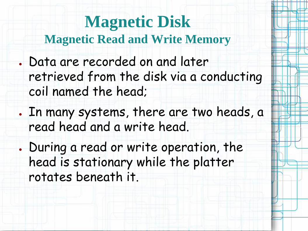
● Data are recorded on and later retrieved from the disk via a conducting coil named the head;
● In many systems, there are two heads, a read head and a write head.
● During a read or write operation, the head is stationary while the platter rotates beneath it.
Magnetic DiskMagnetic Read and Write Memory

● The write mechanism exploits the fact that electricity flowing through a coil produces a magnetic field.
● Electric pulses are sent to the write head, and the resulting magnetic patterns are recorded on the surface below, with different patterns for positive and negative currents.
Magnetic DiskMagnetic Read and Write Memory
● The traditional read mechanism exploits the fact that a magnetic field moving relative to a coil produces an electrical current in the coil.
● When the surface of the disk passes under the head, it generates a current of the same polarity as the one already recorded.
Magnetic DiskMagnetic Read and Write Memory

● The structure of the head for reading is in this case essentially the same as for writing and therefore the same head can be used for both.
● Such single heads are used in floppy disk systems and in older rigid disk systems.
Magnetic DiskMagnetic Read and Write Memory

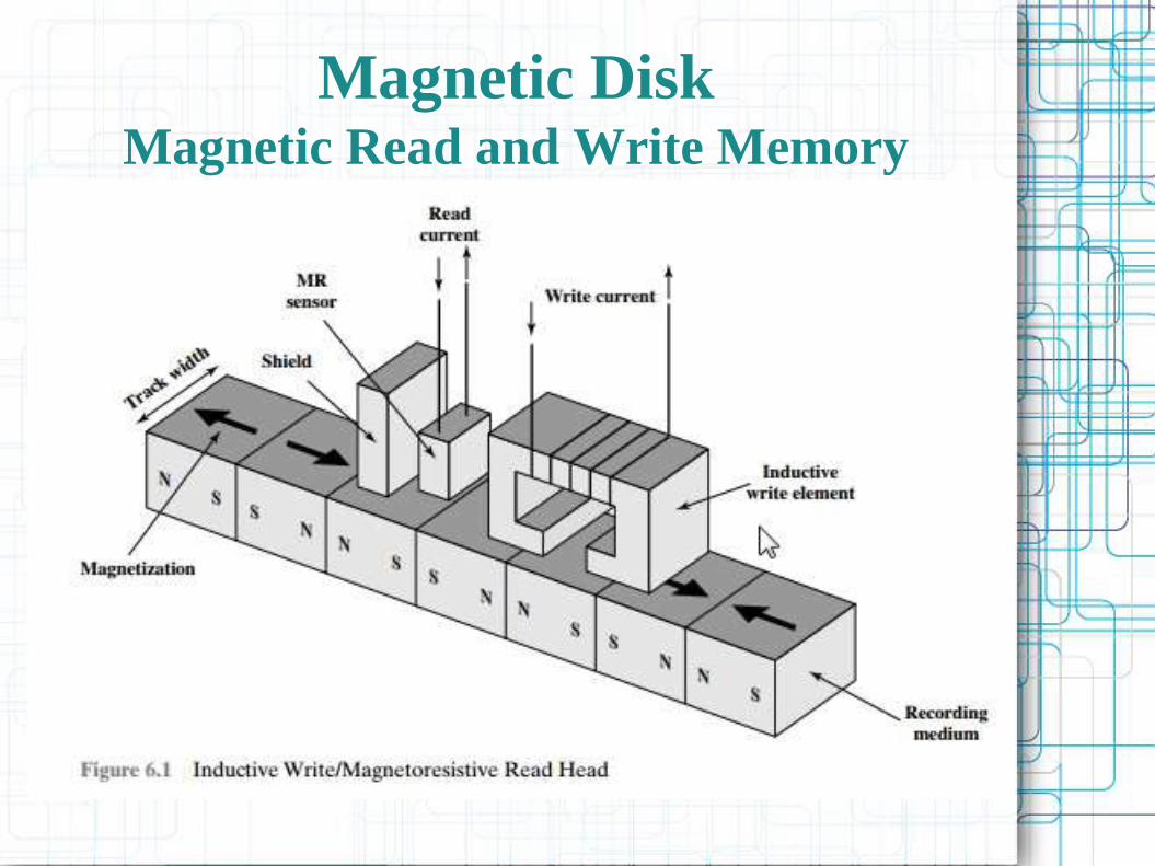
● The read head consists of a partially shielded magneto resistive (MR) sensor. The MR material has an electrical resistance that depends on the direction of the magnetization of the medium moving under it.
Magnetic DiskMagnetic Read and Write Memory

Magnetic DiskData Organization and Formatting
● The head is a relatively small device capable of reading from or writing to a portion of the platter rotating beneath it.
● This gives rise to the organization of data on the platter in a concentric set of rings, called tracks.
● Each track is the same width as the head.There are thousands of tracks per surface.

Magnetic DiskData Organization and Formatting
● Adjacent tracks are separated by gaps.
● This prevents, or at least minimizes, errors due to misalignment of the head or simply interference of magnetic fields.
● Data are transferred to and from the disk in sectors
Magnetic DiskData Organization and Formatting

● In most contemporary systems, fixed-length sectors are used, with 512 bytes being the nearly universal sector size.
● To avoid imposing unreasonable precision requirements on the system, adjacent sectors are separated by intratrack (intersector) gaps.
Magnetic DiskData Organization and Formatting
Magnetic DiskData Organization and Formatting
Magnetic DiskData Organization and Formatting
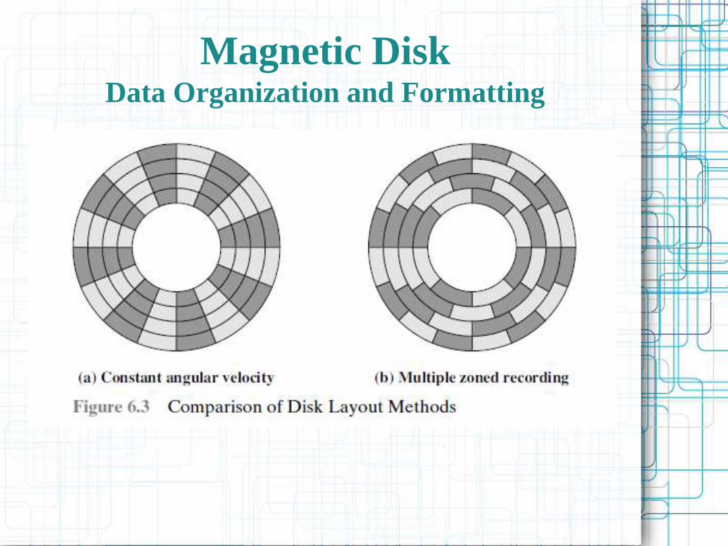
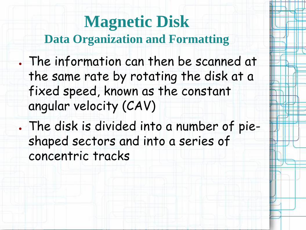
● The information can then be scanned at the same rate by rotating the disk at a fixed speed, known as the constant angular velocity (CAV)
● The disk is divided into a number of pie-shaped sectors and into a series of concentric tracks

Magnetic DiskData Organization and Formatting
● The advantage of using CAV is that individual blocks of data can be directly addressed by track and sector
● The disadvantage of CAV is that the amount of data that can be stored on the long outer tracks is the only same as what can be stored on the short inner tracks
Magnetic DiskData Organization and Formatting
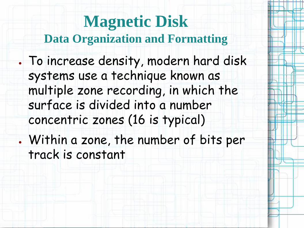
● To increase density, modern hard disk systems use a technique known as multiple zone recording, in which the surface is divided into a number concentric zones (16 is typical)
● Within a zone, the number of bits per track is constant

Magnetic DiskData Organization and Formatting
● Zones farther from the center contain more bits (more sectors) than zones closer to the center
● This allows for greater overall storage capacity at the expense of somewhat more complex circuitry

Magnetic DiskPhysical Characteristics
Magnetic DiskPhysical Characteristics
Magnetic DiskPhysical Characteristics
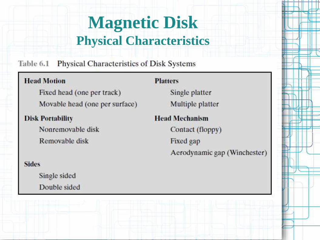
● In a fixed-head disk, there is one read-write head per track
● All of the heads are mounted on a rigid arm that extends across all tracks; such systems are rare today
Magnetic DiskPhysical Characteristics
● In a movable-head disk, there is only one read-write head
● Again, the head is mounted on an arm
● Because the head must be able to be positioned above any track, the arm can be extended or retracted for this purpose
Magnetic DiskPhysical Characteristics
● A nonremovable disk is permanently mounted in the disk drive; the hard disk in a personal computer is a nonremovable disk
● A removable disk can be removed and replaced with another disk

Magnetic DiskPhysical Characteristics
● For most disks, the magnetizablecoating is applied to both sides of the platter, which is then referred to as double sided
● Some less expensive disk systems use single-sided disks

Magnetic DiskPhysical Characteristics

Magnetic DiskPhysical Characteristics
● Multiple–platter disks employ a movable head, with one read-write head per platter surface
● All of the heads are mechanically fixed so that all are at the same distance from the center of the disk and move together
Magnetic DiskPhysical Characteristics
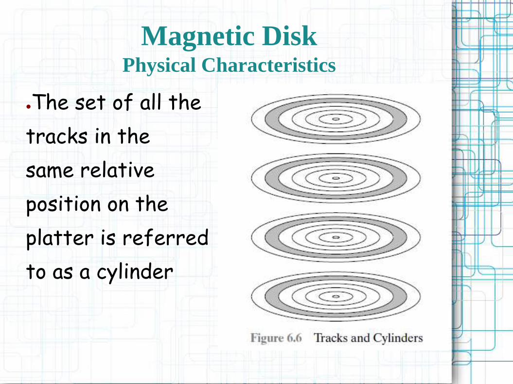
●The set of all the
tracks in the
same relative
position on the
platter is referred
to as a cylinder
Magnetic DiskPhysical Characteristics
● This mechanism is used with the floppy disk, which is a small, flexible platter and the least expensive type of disk
● Winchester heads are used in sealed drive assemblies that are almost free of contaminants

Magnetic DiskPhysical Characteristics

Magnetic DiskPhysical Characteristics
● The term Winchester was originally used by IBM as a code name for the 3340 disk model prior to its announcement
● The Winchester disk is commonly found built in to personal computers and workstations, where it is referred to as a hard disk
Magnetic DiskPhysical Characteristics

Magnetic DiskPhysical Characteristics
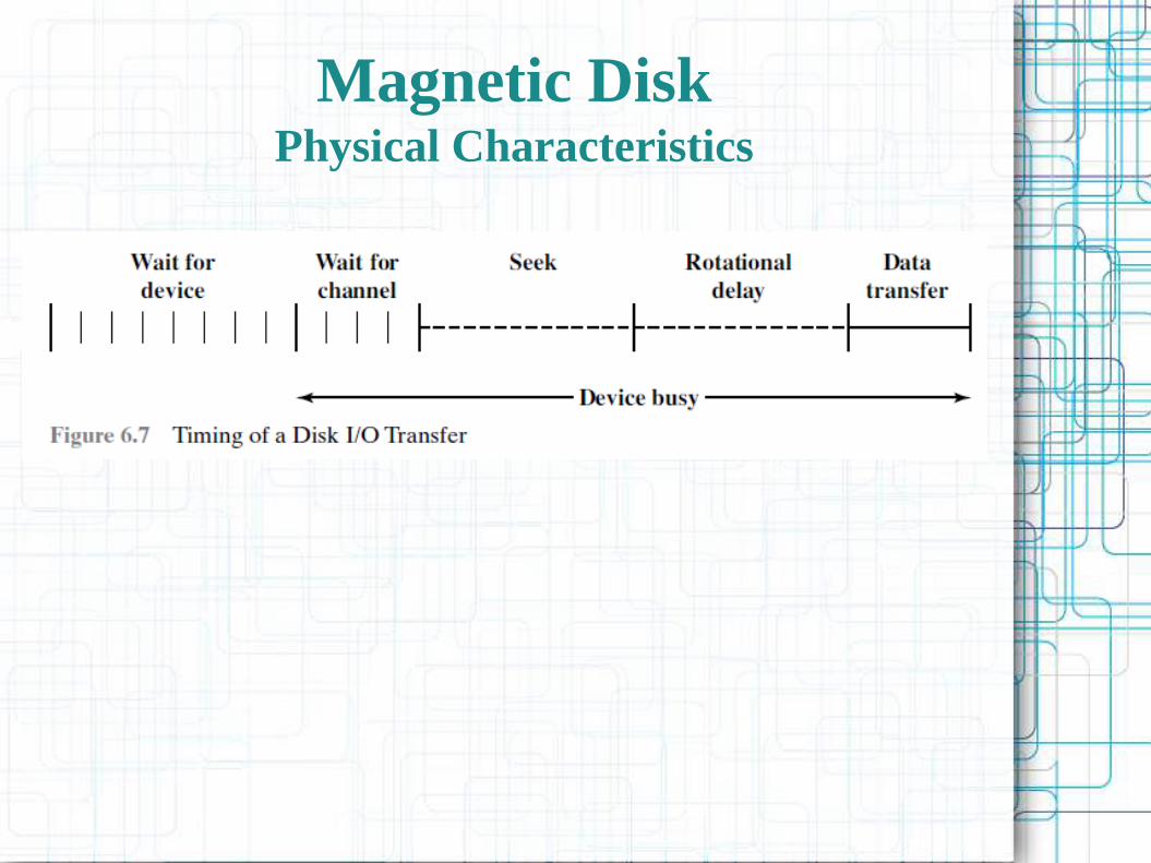
● On a movablehead system, the time it takes to position the head at the track is known as seek time
● The time it takes for the beginning of the sector to reach the head is known as rotational delay, or rotational latency
Magnetic DiskPhysical Characteristics
● The sum of the seek time, if any, and the rotational delay equals the access time, which is the time it takes to get into position to read or write
● Once the head is in position ,the read or write operation is then performed as the sector moves under the head; this is the data transfer portion of the operation; the time required for the transfer is the transfer time
Magnetic DiskPhysical Characteristics
● SEEK TIME
– Seek time is the time required to move the disk
arm to the required track
– It turns out that this is a difficult quantity to pin
down

Magnetic DiskPhysical Characteristics
● ROTATIONAL DELAY
–Disks, other than floppy disks, rotate at speeds ranging from 3600 rpm (for handheld devices such as digital cameras) up to, as of this writing, 20,000 rpm; at this latter speed, there is one revolution per 3 ms
–Thus, on the average, the rotational delay will be 1.5 ms

Magnetic DiskPhysical Characteristics
● TRANSFER TIME
– The transfer time to or from the disk depends on the rotation speed of the disk in the following fashion:
Magnetic DiskPhysical Characteristics
●A TIMING COMPARISON
–With the foregoing parameters defined, let us look at two different I/O operations that illustrate the danger of relying on average values
Magnetic DiskPhysical Characteristics
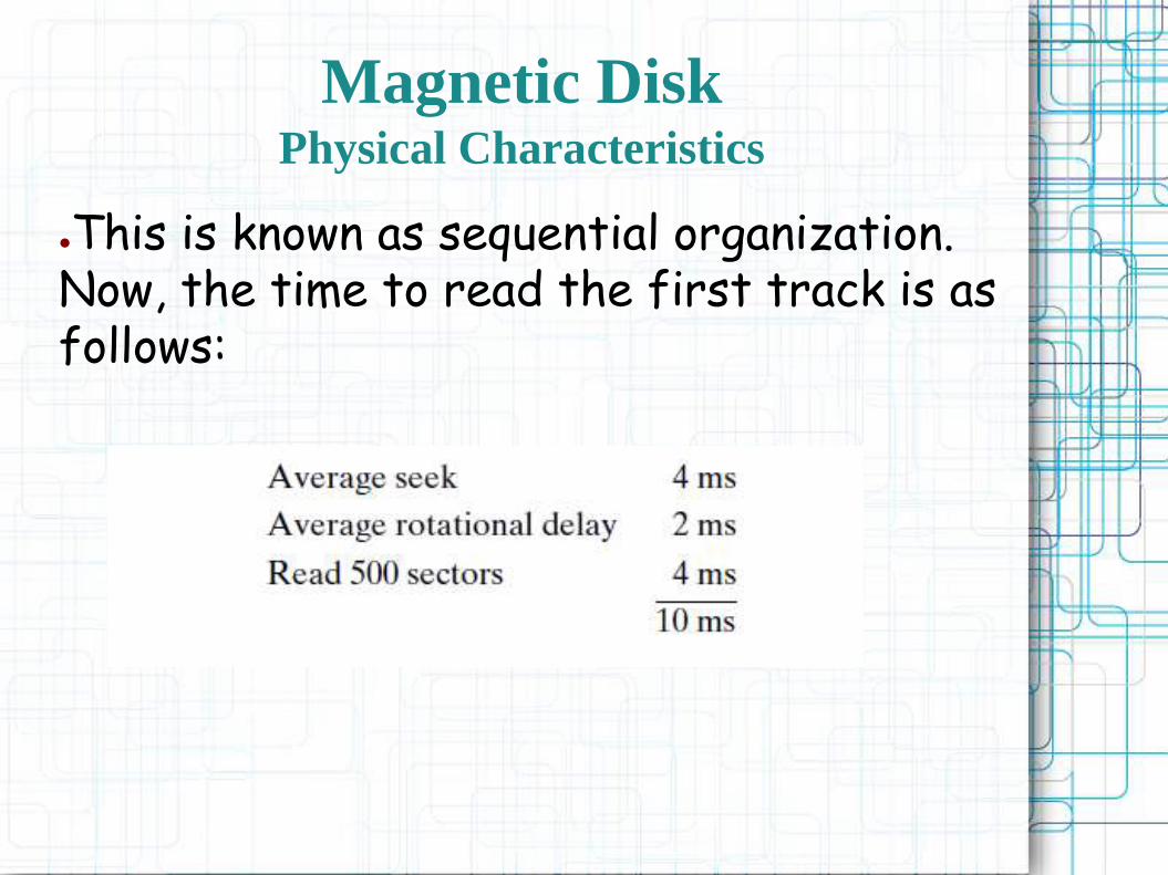
●This is known as sequential organization. Now, the time to read the first track is as follows:

RAID
● RAID (originally redundant array of inexpensive disks; now commonly redundant array of independent disks)
– is a data storage virtualization technology that combines multiple disk drive components into a logical unit for the purposes of data redundancy or performance improvement

RAID
● 6 (of 7) levels in common use
– 0, 1, 3 used for high transfer rate
– 4, 5, 6 used for high transaction rate
● Not a hierarchy
● Set of physical disks viewed as single logical drive by O/S
● Data distributed across physical drives
● Can use redundant capacity to store parity information
RAID
RAIDI/O Transfer Rate and I/O Request Rate
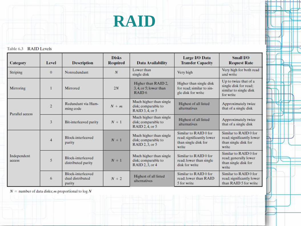
● Note the last two columns in table
– Transfer Rate and I/O Request Rate are not the same!
– High transfer rate useful when large blocks of data have to read (or written); e.g., large database
– Ability to satisfy high I/O request rate useful when many small independent requests have to satisfied; e.g., web server, mail server, database server, multi-user computing, other transaction-oriented environments

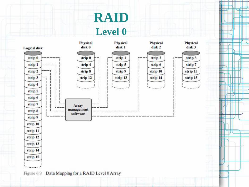
RAIDLevel 0
● No redundancy
● Appears as logical disk on which all data is stored: an abstraction of the real disk(s)
● Data is placed in segments called strips
– A stripe is all of the strips at the same location on all of the disks
– Strips are placed on disks in round-robin:

RAIDLevel 0 Layout
RAIDLevel 0

RAIDLevel 0 Performance
● Depends on
– High transfer capacity on entire path to memory
– Application data requests need to drive I/O efficiently, either:
● Large requests for logically contiguous data that can be satisfied by parallel access to different disks, or
● Many small requests, each of which requires access to a single strip of a disk
– Strip size has to be balanced with typical I/O patterns
– Depends on whether you want large transfer capacity or high I/O request rate
RAIDRedundancy
● RAID 0 does not provide redundant storage
● RAID 1 provides redundant storage in the simplest form: data is duplicated on mirrored disks
● RAID 2-6 provide redundancy through parity calculations
RAIDLevel 1
● Mirrored Disks
– Data is (usually) striped across disks
● Each logical stripe mapped to 2 disks
– Read from either
– Write to both
– Recovery is simple
● Swap faulty disk & re-mirror
● No down time
– Relatively expensive: double disks

RAIDLevel 1 Layout

RAIDLevel 1 Pros and Cons
– Expensive (2 disks per logical disk)
● usually used for system or other highly critical data only
– Can achieve very high transfer rates (2 x RAID0) in transaction-oriented environment but only if most requests are Reads
– Write are limited to the slower of the two drives

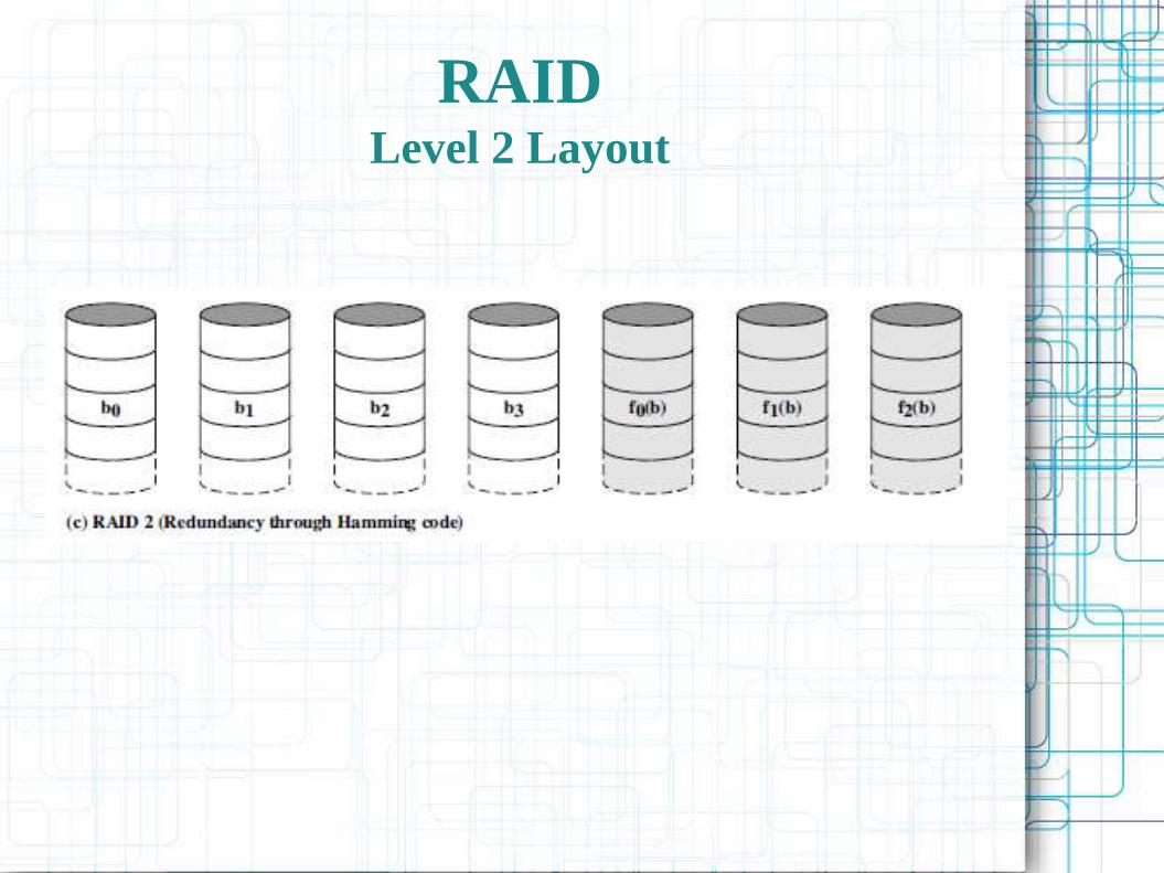
RAIDLevel 2
● Parallel access across all disks for each I/O request
● Requires synchronized disks and specialized controllers
– Very small strips, single byte/word
● Data split at bit level across disks
– Error correction calculated across corresponding bits on disks
● Multiple parity disks store Hamming code error correction in corresponding positions
– Lots of redundancy
● Expensive
● No longer used; most disks incorporate ECC already
RAIDLevel 2 Layout

RAIDLevel 3
– Similar to RAID 2, but only one redundant disk, no matter how large the array
– Data is striped at the byte level; a block of data has parts written to each drive
– Simple parity bit for each set of corresponding bits
– Data on failed drive can be reconstructed from surviving data and parity info
– Very high transfer rates, but low I/O request rates (1 at a time, because all disks are involved in each I/O)
– RAID 3 is not common; poor I/O request performance

RAIDLevel 3 Layout

RAIDLevel 4
– Each disk operates independently
– Good for high I/O request rate
– Large strips (e.g., 16k or 32k)
– Bit by bit parity calculated across stripes on each disk
– Parity stored on parity disk
– Poor write performance on small requests
– The single parity drive is a bottleneck

RAIDLevel 4 Layout

RAIDLevel 5
– One of the most widely used RAID schemes
– Similar to RAID 4, but parity striped across ALL disks
– Round robin allocation for parity stripe
– Avoids RAID 4 bottleneck at parity disk
– Commonly used in network servers

RAIDLevel 5 Layout

RAIDLevel 6
– Two parity calculations
– Stored in separate blocks on different disks
– User requirement of N disks needs N+2
– High data availability
● Three disks need to fail for data loss
● Significant write penalty
– Rarely used because possibility of multiple simultaneous disk failure is very slim
– Catastrophic events would normally destroy most or all disks

RAIDLevel 6 Layout

RAIDComparison

RAIDComparison

Optical Memory
● In 1983, one of the most successful consumer products of all time was introduced:
● the compact disk (CD) digital audio system.
– A non-erasable disk that can store more than 60 minutes of audio information on one side.
● A variety of optical-disk systems have been introduced.

Optical Memory

Optical Memory
● CD-ROM
– Both the audio CD and the CD-ROM (compact disk read-only memory) share a similar technology.
● The main difference is that CD-ROM players are more rugged and have error correction devices to ensure that data are properly transferred from disk to computer.
Compact DiskCD-ROM
● Information is retrieved from a CD or CD-ROM by a low-powered laser housed in an optical-disk player, or drive unit;
● Digitally recorded information (either music or computer data) is imprinted as a series of microscopic pits on the surface of the polycarbonate;
● Information is retrieved from a CD or CD-ROM by a low-powered laser housed in an optical-disk player, or drive unit.
Compact DiskCD-ROM
● The areas between pits are called lands.
● Land - a smooth surface, which reflects back at
higher intensity;
● The change between pits and lands is detected
by a photo sensor and converted into a digital
signal.
Compact DiskCD-ROM

● To achieve greater capacity, CDs and CD-
ROMs do not organize information on
concentric tracks. Instead, the disk contains a
single spiral track, beginning near the center
and spiraling out to the outer edge of the disk.
Compact DiskCD-ROM

Compact DiskCD-ROM
● The pits are then read by the laser at a constant
linear velocity (CLV).
● The disk rotates more slowly for accesses near
the outer edge than for those near the center.
● Thus, the capacity of a track and the rotational
delay both increase for positions nearer the
outer edge of the disk.
● The data capacity for a CD-ROM is about 680
MB
Compact DiskCD-ROM
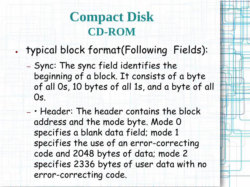
● typical block format(Following Fields):
– Sync: The sync field identifies the beginning of a block. It consists of a byte of all 0s, 10 bytes of all 1s, and a byte of all 0s.
– • Header: The header contains the block address and the mode byte. Mode 0 specifies a blank data field; mode 1 specifies the use of an error-correcting code and 2048 bytes of data; mode 2 specifies 2336 bytes of user data with no error-correcting code.
Compact DiskCD-ROM

– Data: User data.
– Auxiliary: Additional user data in mode 2. In mode 1, this is a 288-byte error correcting code.
● With the use of CLV, random access becomes more difficult. Locating a specific address involves moving the head to the general area, adjusting the rotation speed and reading the address, and then making minor adjustments to find and access the specific sector.
Compact DiskCD-ROM

● CD-ROM has two advantages:
– it can be mass replicated inexpensively;
– The optical disk is removable, allowing the disk itself to be used for archival storage.
● CD-ROM disadvantages :
– It is read-only and cannot be updated;
– It has an access time much longer than that of a magnetic disk drive, as much as half a second.
Compact DiskCD-ROM

● Write-once read-many CD, known as the CD recordable (CD-R)
● It is used to accommodate applications in which only one or a small number of copies of a set of data is needed;
● a disk is prepared in such a way that it can be subsequently written once with a laser beam of modest intensity
Compact DiskCD Recordable
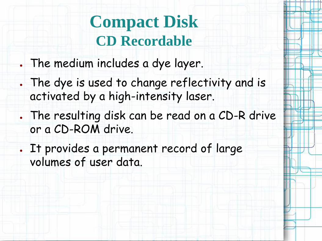
● The medium includes a dye layer.
● The dye is used to change reflectivity and is activated by a high-intensity laser.
● The resulting disk can be read on a CD-R drive or a CD-ROM drive.
● It provides a permanent record of large volumes of user data.
Compact DiskCD Recordable

● The CD-RW optical disk can be repeatedly written and overwritten, as with a magnetic disk
● The only pure optical approach that has proved attractive is called phase change.
● Phase change disk uses a material that has two significantly different reflectivities in two different phase states.
Compact DiskCD Rewritable
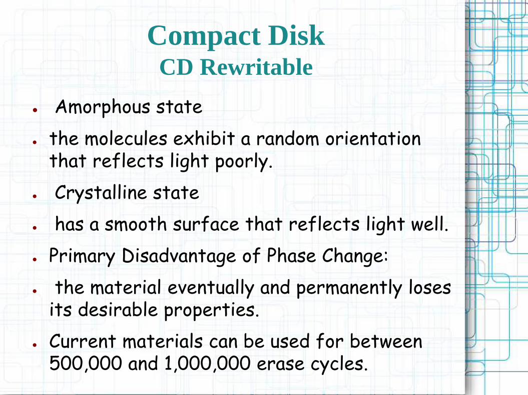
● Amorphous state
● the molecules exhibit a random orientation that reflects light poorly.
● Crystalline state
● has a smooth surface that reflects light well.
● Primary Disadvantage of Phase Change:
● the material eventually and permanently loses its desirable properties.
● Current materials can be used for between 500,000 and 1,000,000 erase cycles.
Compact DiskCD Rewritable

● CD-RW has the obvious advantage over CD-ROM and CD-R:
– it can be rewritten and thus used as a true secondary storage.
● key advantage of the optical disk
– the engineering tolerances for optical disks are much less severe than for high-capacity magnetic disks.
– Thus, they exhibit higher reliability and longer life.
Compact DiskCD Rewritable
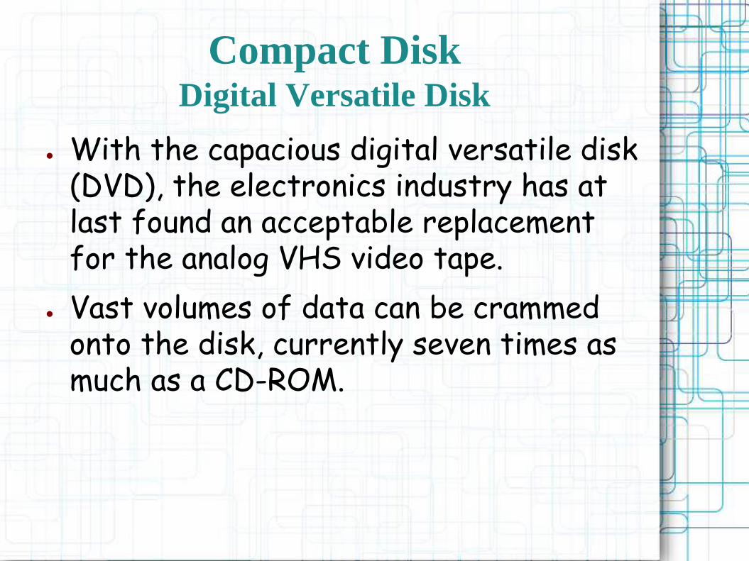
● With the capacious digital versatile disk (DVD), the electronics industry has at last found an acceptable replacement for the analog VHS video tape.
● Vast volumes of data can be crammed onto the disk, currently seven times as much as a CD-ROM.
Compact DiskDigital Versatile Disk

Compact DiskDigital Versatile Disk
● The DVD’s greater capacity is due to three differences from CDs:
1. Bits are packed more closely on a DVD. The spacing between loops of a spiral on a CD is 1.6 m and the minimum distance between pits along the spiral is 0.834 m. The DVD uses a laser with shorter wavelength and achieves a loop spacing of 0.74 m and a minimum distance between pits of 0.4 m. The result of these two improvements is about a seven-fold increase in capacity, to about 4.7 GB.
Digital Versatile Disk
3 Differences from CDs

2. The DVD employs a second layer of pits and lands on top of the first layer.Aduallayer DVD has a semireflective layer on top of the reflective layer, and by adjusting focus, the lasers in DVD drives can read each layer separately.This technique almost doubles the capacity of the disk, to about 8.5 GB.The lower reflectivity of the second layer limits its storage capacity so that a full doubling is not achieved.
3. The DVD-ROM can be two sided, whereas data are recorded on only one side of a CD. This brings total capacity up to 17 GB.
Digital Versatile Disk
3 Differences from CDs

Optical Memory Characteristics
● Designed to store high-definition videos and to provide significantly greater storage capacity compared to DVDs.
● The higher bit density is achieved by using a laser with a shorter wavelength, in the blue-violet range.
● The data pits, which constitute the digital 1s and 0s, are smaller on the high-definition optical disks compared to DVD because of the shorter laser wavelength.
Compact DiskHigh-Definition Optical Disks
● The Blu-ray scheme ultimately achieved market dominance;
● The HD DVD scheme can store 15 GB on a single layer on a single side;
● Blu-ray positions the data layer on the disk closer to the laser;
High-Definition Optical Disks
VS
Blu-ray DVD

● This enables a tighter focus and less distortion and thus smaller pits and tracks.
● Blu-ray can store 25 GB on a single layer.
● Three versions are available: read only (BD-ROM), recordable once (BD-R), and rerecordable (BD-RE).
High-Definition Optical Disks
VS
Blu-ray DVD
Magnetic Tape
● Tape systems use the same reading and recording techniques as disk systems. The medium is flexible polyester (similar to that used in some clothing) tape coated with magnetizable material.
● Tapes used to be packaged as open reels that have to be threaded through a second spindle for use. Today, virtually all tapes are housed in cartridges.

● Data on the tape are structured as a number of parallel tracks running lengthwise
● The recording of data in this form is referred to as parallel recording.
● Most modern systems instead use serial recording, in which data are laid out as a sequence of bits along each track, as is done with magnetic disks
Magnetic Tape

● As with the disk, data are read and written in contiguous blocks, called physical records, on a tape. Blocks on the tape are separated by gaps referred to as interrecord gaps.
● As with the disk, the tape is formatted to assist in locating physical records.
Magnetic Tape

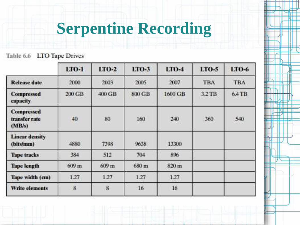
Serpentine Recording
● Technique used in serial tapes where in this technique, when data are being recorded, the first set of bits is recorded along the whole length of the tape.
● When the end of the tape is reached, the heads are repositioned to record a new track, and the tape is again recorded on its whole length, this time in the opposite direction. That process continues, back and forth, until the tape is full.

Serpentine Recording

Serpentine Recording
Serpentine Recording
● A tape drive is a sequential-access device. If the tape head is positioned at record 1, then to read record N, it is necessary to read physical records 1 through N 1, one at a time;
● If the head is currently positioned beyond the desired record, it is necessary to rewind the tape a certain distance and begin reading forward. Unlike the disk, the tape is in motion only during a read or write operation.
Magnetic Tape

● In contrast to the tape, the disk drive is referred to as a direct-access device.
● A disk drive need not read all the sectors on a disk sequentially to get to the desired one.
● It must only wait for the intervening sectors within one track and can make successive accesses to any track.
Magnetic Tape
● Magnetic tape was the first kind of secondary memory. It is still widely used as the lowest-cost, slowest-speed member of the memory hierarchy.
● The dominant tape technology today is a cartridge system known as linear tape-open (LTO). LTO was developed in the late 1990s as an open-source alternative to the various proprietary systems on the market.
Magnetic Tape