external product specification for the mcs-51 …plit.de/asem-51/omf51eps.pdf · mcs-51 object...
TRANSCRIPT

EXTERNAL PRODUCT SPECIFICATION
FOR THE
MCS-51 OBJECT MODULE FORMAT
V5.0
APPROVED
Sept. 05, 1982

MCS-51 OBJECT MODULE FORMAT EPS VERSION 5.0
INTEL CORPORATION REVISION SHEETA 2
TABLE OF CONTENTS
1 PREFACE ...........................................................................................................32 OVERVIEW OF 8051 ARCHITECTURE .............................................................3
2.1 Code Space...........................................................................................32.2 External Data Space..............................................................................42.3 Internal Data Space ...............................................................................4
2.3.1 Register Banks.........................................................................52.3.2 Bit Space..................................................................................52.3.3 Hardware Registers .................................................................52.3.4 Stack ........................................................................................52.3.5 Additional RAM (RUPI).............................................................52.3.6 Addressing Modes ...................................................................6
3 REQUIREMENTS ...............................................................................................63.1 Relocatable and External References ...................................................63.2 Segment Relocation ..............................................................................63.3 Intermodule Linkage ..............................................................................73.4 Symbolic Debugging..............................................................................83.5 Compatibility ..........................................................................................83.6 RUPI (And other MCS-51 members) Support........................................8
4 OBJECT FILE STRUCTURE...............................................................................85 RECORD FORMATS ..........................................................................................10
5.1 Notation .................................................................................................105.2 Module Header Record..........................................................................115.3 Module End Record ...............................................................................115.4 Definition Records .................................................................................12
5.4.1 Segment Definitions Record.....................................................125.4.2 External Definitions Record......................................................16
5.5 Debug Records......................................................................................175.5.1 Scope Definition Record...........................................................175.5.2 Debug Items Record ................................................................18
5.6 Data Section ..........................................................................................195.6.1 Content Record ........................................................................205.6.2 Fixup Record............................................................................20
5.7 Library Records .....................................................................................225.7.1 Library Header Record.............................................................235.7.2 Library Module Names Record.................................................235.7.3 Library Module Locations Record.............................................235.7.4 Library Dictionary Record.........................................................24
APPENDIX A: RECORD FORMAT SUMMARY.....................................................25APPENDIX B: GLOSSARY ....................................................................................26APPENDIX C: ABSOLUTE OBJECT MODULE FORMAT .....................................28
C.1 Structure Of Absolute Object File..........................................................28C.2 Module Header Record .........................................................................28C.3 Module End Record ..............................................................................29C.4 Scope Definition Record........................................................................29C.5 Debug Items Record .............................................................................30C.6 Content Record ......................................................................................32

MCS-51 OBJECT MODULE FORMAT EPS VERSION 5.0
INTEL CORPORATION REVISION SHEETA 3
APPENDIX D: DOCUMENT HISTORY ..................................................................33APPENDIX E: REFERENCES ...............................................................................34
DISCLAIMER
Intel makes no representation or warranties with respectto the contents hereof and specifically disclaims anyimplied warranties of merchantability or fitness for anyparticular purpose. Further, Intel reserves the right torevise this publication and to make changes from timeto time in the content hereof without obligation of Intelto notify any person of such revision or changes. Thepublication of this specification should not be construedas a commitment on Intel's part to implement anyproduct.
© 1982 Intel Corporation. All rights reserved.
Document Control Center Number for this MCS-51 OMF EPS is 481984.

MCS-51 OBJECT MODULE FORMAT EPS VERSION 5.0
INTEL CORPORATION REVISION SHEETA 4
1 PREFACE
The document defines the internal format of the relocatable object files (Object ModuleFormats, OMF) for the 8051 family, produced by Intel's language translators andprocessed by other Intel software products. Appendix C defines the Absolute ObjectModule Format (AOMF) which is produced by the RL51 program (and the RASM, if thesource program is absolute). The information in this document is normally not neededin order to use Intel software, but is provided for the person who needs to writeprograms to process these object files or to create files in the same formats. Thedesign is heavily based on the previous OMFs for the 8080 and the 8086 [1] [2].
Chapter 2 covers some background material for those interested in the relevant 8051architecture issues and the R&L requirements which led to the definition of the objectfile formats.
Terms which may have special meaning in the document are described in the glossary(Appendix B).
2 OVERVIEW OF 8051 ARCHITECTURE
The following discussion outlines those aspects of the 8051 architecture relevant tolinking and locating - the memory model and the addressing modes.
The memory model of the 8051 family consists of three non-overlapping addressspaces - the code space, the external data space and the on-chip RAM. Some sectionsof the on-chip RAM space serve functions in addition to being the usual random accessbyte storage. These include bit-addressable memory, and stack.
2.1 Code Space
The code space size is 64K bytes. The lower 4K are on-chip ROM and the top 60Kresides in external memory components. The lower portion of the on-chip ROMcontains a reset vector (at location 0) and 5 interrupt vectors (at locations 3, 0BH, 13H,1BH and 23H).
The code space usually consists of all the procedure and constants of a program. It isassumed that all the code space (off-chip as well) consists of ROM. Consequently onlyread operations are available on data in the code space.
Four code addressing modes are provided:a. Direct Addressing - The second and third byte of the instruction form the full 16 bit
address (used in jump and call instructions). Setup instruction (MOV DPTR,code_address).
b. Block addressing - The instruction provides the 11 least-significant bits of theaddress. The block address is defined by the 5 most-significant bits of theincremented PC. Used in jump and call instructions.

MCS-51 OBJECT MODULE FORMAT EPS VERSION 5.0
INTEL CORPORATION REVISION SHEETA 5
c. Relative Addressing - The instruction provide 8 bit relative offset. Used inconditional jumps in a range of +127/-128 of the incremented PC.
d. Indirect Addressing - The address is composed of the DPTR or PC content,indexed by the 8 bit accumulator.
2.2 External Data Space
The External Data space size is 64K bytes. This space is completely external to thechip. Access is provided via move instructions which move bytes between the externaldata space and the accumulator.
Two external data addressing modes are provided:a. Indirect DPTR - the 16 bit DPTR is used to address any location in the external
data space.b. Indirect Register - R0 or R1 are used to address a location within a 256 byte page
defined by the content of the Port 2 register.
The pointing registers DPTR, R0 and R1 should be set up before the actual access isbeing made. The machine provide instructions for loading the DPTR with a constant(e.g. external data address) and incrementing it. It provides many instructions whichload/manipulate the 8 bit pointers R0 and R1.
2.3 Internal Data Space
The on-chip RAM space consists of 128 bytes (up to 256 bytes for a few members ofthe family , e.g. 192 for the RUPI) of data memory and 128 bytes of memory mappedhardware registers. The on-chip RAM space is organized as follows:
DIRECT ADDRESSING INDIRECT ADDRESSING256 Hardware Registers Future Additional RAM192 RUPI Additional RAM128 Free RAM
48 Bit Space32 Register Bank 324 Register Bank 216 Register Bank 1 Default TOS
8 Register Bank 00
The function of the various components of the on-chip RAM space and the addressingmodes by which they may be accessed are discussed below.
2.3.1 Register Banks
The lower 32 bytes of the on-chip RAM space are divided into four register banks,usually associated with different interrupt nesting levels. The eight registers of the

MCS-51 OBJECT MODULE FORMAT EPS VERSION 5.0
INTEL CORPORATION REVISION SHEETA 6
current bank, selected by two bits within the PSW, are usually used for scratchpadpurposes.
2.3.2 Bit Space
The bit space contain 256 individually addressable bits. Bits 0 to 127 are mapped ontobytes 32 to 47 of the on-chip RAM space. Bits 128 to 255, some of which arenonexistent, are mapped onto some specific registers in the hardware space.Operations on the bit space include SET, CLEAR, COMPLEMENT, AND, OR andTEST.
2.3.3 Hardware Registers
When direct addressing is used, a few (20 for the 8051, 34 for the RUPI) of the top 128bytes of the on-chip RAM space are mapped 1-1 onto a set of hardware registers (A, B,DPTR, etc.). Thus I/O and other accesses to the machine itself are accomplished bydirect memory operations. The result of an access to an unoccupied location within thatsection is undefined.
2.3.4 Stack
The top of the stack is initially set by H/W to 07H (the start of register bank 1) but maybe relocated to anywhere else within the on-chip RAM space by setting the StackPointer (SP).
The stack grows upward, i.e. the SP is incremented before a write operation(PUSH/CALL/ACALL instructions) and is decremented after a read operation(POP/RET/RETI instructions).
The stack is byte oriented. However when used in call/return-type operations, two bytes(a full 16 bit address) are pushed/popped.
2.3.5 Additional RAM (RUPI)
There are 64 bytes of additional on-chip RAM available on the RUPI chip (locations 128to 191). Other members of the family can have up to 128 additional on-chip Ram bytes.These additional bytes can only be accessed in the indirect addressing mode. Theymay be used as memory for the stack.
2.3.6 Addressing Modes
The on-chip RAM space can be accessed using the following addressing modes:a. Direct Addressing - the full 8 bit address is given in the second byte of the
instruction. Addresses greater then 127 access the memory mapped hardwarespace.
b. Indirect Register Addressing - the address is specified by the content of R0 or R1.Addresses greater then 127 address nothing on the 8051 and addresses greaterthen 191 address nothing on the RUPI.

MCS-51 OBJECT MODULE FORMAT EPS VERSION 5.0
INTEL CORPORATION REVISION SHEETA 7
c. Register Addressing - a three bit field in the first (opcode) byte addresses a registerwithin the current register bank.
d. Bit Addressing - this is a direct addressing mode where the full (8-bit) bit address isgiven by the second byte of the instruction.
e. Stack addressing - See 2.3.4.
3 REQUIREMENTS
3.1 Relocatable and External References
The OMF should support relocatable and external references of the following types:a. Low Byte - reference to the low-order byte of an address. Generated by the LOW
operator or, for the DATA and BIT spaces, by a direct (full) address reference.b. High Byte - reference to the high-order byte of an address. Generated by the
HIGH operator. Applicable to XDATA and CODE segments.c. Full CODE/XDATA Address - a full 16-bit reference.d. Inblock CODE Address - an 11-bit inblock reference.e. Relative CODE address - a reference +127/-128 relative to the PC (after it was
incremented to the next instruction).f. Full Bit Address - an 8-bit bit addressg. Mixed Byte/Bit Address - an 8-bit bit address of which only the (5-bit) byte address
part is relocatable.
3.2 Segment Relocation
The object code will be organized in segments. The segments, definedby the user at translation time, will have the following attributes:a. Name - obeys the usual rules for assembly names.b. Segment type - the type of address space to which it belongs (DATA, XDATA,
IDATA, CODE or BIT).c. Relocation type - one of the following types:
1. Absolute - absolute segment. Cannot be relocated by the RL51 program.2. UNIT - a relocatable segment without any restriction concerning its ultimate
location (located on a bit or byte boundary depending on the segment type).3. PAGE - a relocatable segment which must start on a 256 byte page
boundary.4. INPAGE - a relocatable segment which must be contained within a 256 byte
page.5. INBLOCK - a relocatable segment which must be contained within a 2048
byte block.6. BITADDRESSABLE - a relocatable segment of type DATA which must be
contained within the BIT space.d. Size - number of bytes in the segment (number of bits if it is of type BIT).e. Overlayability - each segment will be overlayable or not. Groups of overlayable
segments may occupy the same memory locations if not accessed simultaneously.

MCS-51 OBJECT MODULE FORMAT EPS VERSION 5.0
INTEL CORPORATION REVISION SHEETA 8
For example: overlayable segments are memory locations used for parameterpassing in an HLL program.
The overlaying process involves determining the module call tree. Overlayablesegments from (different) modules which have no calling link between each other canbe overlaid. The united overlaid segment is considered a single segment for theallocation process.
The segments should be relocated and combined under the following rules:a. Segments with the same name should be combined by butting them up against
one another. They must have the same segment type. Their relocation types musteither be the same or a mixture of two types where one of the two is UNIT.
b. The resulting segment should have the same name and type. Its relocation typewill be that of its components or, if the components specify two types then one ofthem be UNIT and the result will be the more restrictive type. Its size will be thesum of the sizes of its components.
c. The user should be able to assign an absolute location to the combined segment(unless it is an absolute segment).
3.3 Intermodule Linkage
The intermodule linkage will be based on the usual notion of a single public definition inone module and a number of external references in some other modules. Theinformation supplied with the public and external symbols should enable the RL51program to:a. Accomplish the two pass algorithm defined in the PIP for the 8051 R&L Package.b. Check symbol information matching between an external definition and a public
definition.c. Set up the undetermined attributes of an external reference.d. Relocate an external reference.
3.4 Symbolic Debugging
The OMF should support the following debugging features:a. Provide name, segment and offset information for local and public symbols.b. Support symbolic debugging by statement numbers.c. Associate symbols and statement numbers with the module name in which they
were defined.d. Provide means of conveying symbol names scope information.
3.5 Compatibility
All object files containing 8051 object code should adhere to the definition given in thisdocument. In particular, the output of the assembler, the PL/M-51 compiler and theoutput of the RL51 program should adhere to this standard.

MCS-51 OBJECT MODULE FORMAT EPS VERSION 5.0
INTEL CORPORATION REVISION SHEETA 9
The absolute object file generated by the RL51 program will be defined by a propersubset of the OMF, called the Absolute Object Module Format (AOMF), defined inAppendix C. The AOMF will be compatible with the ISIS tools which processes filesformatted as 8080 Absolute Object Module Format [4]: the OBJHEX and the UPMprograms.
A stand-alone assembly program without any relocatable segments and externalreferences will also be translated by the RASM into an AOMF type object file.
A new version of the ICE51 is desired, which will accept AOMF type files. Until then theOBJHEX program will be used to convert these files into the current ICE51 format.Note that OBJHEX purges all debug information present in its input object file.
The OMFs should contain hooks to allow the addition of library facilities.
3.6 RUPI (And other MCS-51 members) Support
From RL51 viewpoint, members of the MCS-51 family differ from each other only by theamount of additional on-chip RAM available. This space is available in the RASM viasegments of type IDATA. This information must be supplied to RL51 in order to be ableto check the RAM requirements can be satisfied.
4 OBJECT FILE STRUCTURE
An object file is defined by a sequence of records. The following syntax shows whatsequences of records are valid, and the following semantics gives important informationthat is conveyed by the sequence, rather than mere content, of records. Definition ofvalid string of records is given by the following syntax: (Note: <ITEM>* means that the<ITEM> can occur zero or more times.)
<object file> ::= <module>* | <library>
<module> ::= MODULE_HEADER_RECORD<definition record>*<data/debug record>*MODULE_END_RECORD
<definition record> ::= SEGMENT_DEFINITIONS_RECORD| PUBLIC_DEFINITIONS_RECORD| EXTERNAL_DEFINITIONS_RECORD
<data/debug record> ::= <data section>| <debug record>
<debug record> ::= SCOPE_DEFINITION_RECORD| DEBUG_ITEMS_RECORD
MCS-51 OBJECT MODULE FORMAT EPS VERSION 5.0
INTEL CORPORATION REVISION SHEETA 10
<data section> ::= CONTENT_RECORDFIXUP_RECORD*
<library> ::= LIB_HEADER_RECORD<module>*LIB_MODULE_NAMES_RECORDLIB_MODULE_LOCATIONS_RECORDLIB_DICTIONARY_RECORD
An object file can be a sequence of modules or a library. A module consists of a pair ofModule Header and Module End records enclosing the module body. The body of themodule consists of a definition part and a sequence of debug records and data sections.
The definition part contains a set of records which specifies the segment within themodule, the public symbols which resides in the module and the external names used init.
Debug records contain Debug Items Records about segment symbols, publics symbols,symbols local to the module and the location of the higher level statements ('linenumbers'). They may possibly be enclosed within a pair of Scope Definition Records.
A data section consists of a Content Record which is an image of a section of code anda set of Fixup records which are used by the RL51 program to relocate that section andresolve external references contained in it.
A library file consists of a Library Header Record followed by a set of modules andterminated by three records. These last records list the names of the modules, theirlocation in the file and the lists of the public symbols defined in each of the modules.
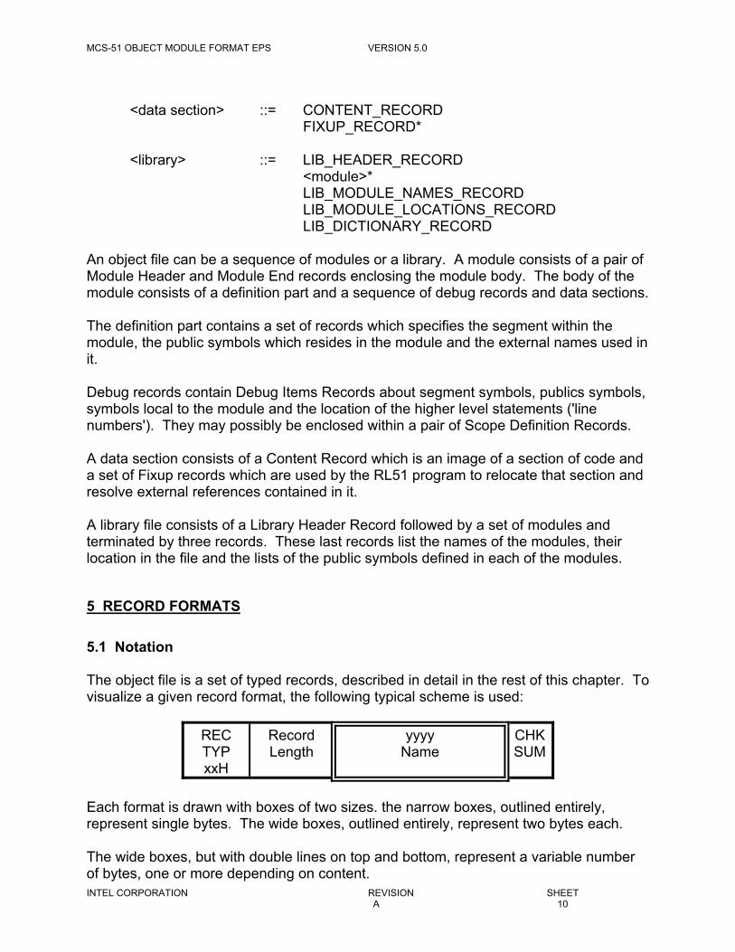
5 RECORD FORMATS
5.1 Notation
The object file is a set of typed records, described in detail in the rest of this chapter. Tovisualize a given record format, the following typical scheme is used:
RECTYPxxH
RecordLength
yyyyName
CHKSUM
Each format is drawn with boxes of two sizes. the narrow boxes, outlined entirely,represent single bytes. The wide boxes, outlined entirely, represent two bytes each.
The wide boxes, but with double lines on top and bottom, represent a variable numberof bytes, one or more depending on content.

MCS-51 OBJECT MODULE FORMAT EPS VERSION 5.0
INTEL CORPORATION REVISION SHEETA 11
Any field that indicates NAME has the following internal structure: the 1st byte containsa number between 0 and 40, inclusive, that indicates the number of remaining bytes inthe field. The remaining bytes are interpreted as a byte string; each byte mustrepresent a member of the following subset of the ASCII character set: {upper caseletters (A..Z), decimal digits (0..9), the special characters "_", "?" and "@"}.
Some portions of a record may be repeated 0 or more times. These are indicated"repeated" or "rept" below the boxes.
The shaded fields are fields which carry no information. They are present to enablefuture enhancements (e.g. SYMBOL TYPE fields) or for compatibility reasons andshould have a zero value.
Each record starts with a record type which indicates the type of the record, and recordlength which contain the number of bytes in the record exclusive of the first two fields.The record ends with a checksum byte which contains the 2's complement of the sum(modulo 256) of all other bytes in the record. Therefore the sum (modulo 256) of allbytes in the record is zero.
Some byte fields contain bit subfields. To describe them the following scheme is used:
7 6 5 4 3 2 1 0
Field_1 Field_0
In the above example the byte contain two fields: FIELD_1 from bit 3 to bit 7 andFIELD_0 from bit 0 to bit 2.
In the following sections an absolute address is a 16 bit integer representing an offsetfrom the beginning of the corresponding address space, in bits for a BIT type and inbytes otherwise. An OFFSET field is a 16 bit integer representing an offset from thebeginning of the corresponding segment, in bits for a BIT type and in bytes otherwise.
In the following record descriptions, whenever a field can assume only a discrete set ofvalues (e.g. TRN ID in Module Header record), the unused values are reserved forfuture expansion. In particular, unused record types are reserved for future use.
5.2 Module Header Record
RECTYP02H
RecordLength
ModuleName
TRNID
CHKSUM
Each module must starts with a module header record. It is used to identify the modulefor the RL51 and other future processors of 8051 object files. In addition to the ModuleName the record contain:

MCS-51 OBJECT MODULE FORMAT EPS VERSION 5.0
INTEL CORPORATION REVISION SHEETA 12
TRN ID
The byte identifies the program which has generated this module: 0FDH - ASM51,0FEH - PL/M-51, 0FFH - RL51.
5.3 Module End Record
RECTYP04H
RecordLength
ModuleName
REGMSK
CHKSUM
The record ends the module sequence and contains the following information:characteristics
MODULE NAME
The name of the module is given here for a consistency check. It must match the namegiven in the Module Header Record.
REGISTER MASK (REG MSK)
The field contains a bit for each of the four register banks. Each bit, when set specifiesthat the corresponding bank is used by the module:
Bit 0 (the least significant bit) - bank #0.Bit 1 - bank #1.Bit 2 - bank #2.Bit 3 - bank #3.
5.4 Definition Records
The definition part contains the names and other attributes of the segments, publics andexternals used in the module.
The definition part consists of three types of records: Segment Definitions Record,Public Definitions Record and External Definitions Record.
5.4.1 Segment Definitions Record
RECTYP0EH
RecordLength
SegmentDefinition
CHKSUM
← rept →

MCS-51 OBJECT MODULE FORMAT EPS VERSION 5.0
INTEL CORPORATION REVISION SHEETA 13
The record defines segments which are used in the module. The record contains arepetition of segment definitions. Forward references to a segment definition are notallowed. The structure of each segment definition is as follows:
SEGID
SEGINFO
RELTYP
SegmentBase
SegmentSize
SegmentName
SEG ID
The field can have the following values:0 - identifies an absolute segment. Absolute references, within the object
module, do not refer to an absolute segment definition. Absolute segmentscannot be combined and have null (zero length) names.
1 to 255 - identifies a relocatable segment; (SEG ID - 1) must be equal to thesequential number of its definition in the list of the segment definition as theyappear in the module (ignoring the absolute segment definitions!).
Thus the OMF allows for up to 255 relocatable segments and an arbitrary number ofabsolute segments to be defined within a module.
SEG INFO (segment information)
The structure of this field is as follows:
7 6 5 4 3 2 1 0
E OVL SEG REG SEG TYPE
E
This bit specifies (when set) that the segment is of zero size (empty).
OVL
This bit specifies (when set) that the segment is overlayable (i.e. RL51 may overlay thissegment by other compatible overlayable segments).
SEG REG
This field specifies the register bank in which the overlayable segment may be used.The field is meaningful only for overlayable segments.
Bits 3 and 4 have the following meaning:00 - register bank # 0.01 - register bank # 1.10 - register bank # 2.11 - register bank # 3.

MCS-51 OBJECT MODULE FORMAT EPS VERSION 5.0
INTEL CORPORATION REVISION SHEETA 14
The combination of non-zero SEG REG for nonoverlayable segments is reserved forfuture use.
SEG TYPE
This field specifies the type of the segment:0 - CODE.1 - XDATA.2 - DATA.3 - IDATA.4 - BIT.
REL TYP (relocation type)
The relocation type field of a segment can specify an absolute segment and four typesof relocatable segments:
0 - ABS. Specifies an absolute segment (non-relocatable).1 - UNIT. The segment can be relocated on a unit boundary (a bit boundary
for BIT type segments and a byte boundary for all other segments). Thusno restrictions are placed on its relocation.
2 - BITADDRESSABLE. The segment must be located within the bit-addressable portion of the internal data space. Allowed only for DATAtype segments.
3 - INPAGE. The segment will be located within a 256 byte page.4 - INBLOCK. The segment will be located within a 2048 byte block.5 - PAGE. The base address of this segment will be on a 256 byte page
boundary.
The types INPAGE and PAGE are valid only for the CODE and XDATA segment types.INBLOCK is valid only for the CODE segment type.
SEGMENT BASE
This field gives the absolute address of the segment. It is used for absolute segmentsonly. For relocatable segments this field contain zero.
SEGMENT SIZE
The number of bytes (or bits in the case of BIT type segment) occupied by the portion ofthe segment defined in this module. A value of zero specifies a size of 10000H (64K)bytes. This field is ignored if the segment is empty (E is set).
SEGMENT NAME
The name of the segment. Since absolute segments have no names, the field in theircase specifies a null name (zero length).

MCS-51 OBJECT MODULE FORMAT EPS VERSION 5.0
INTEL CORPORATION REVISION SHEETA 15
RECTYP16H
RecordLength
SEG ID
SYMINFO
Offset PublicName
CHKSUM
← rept →
This record defines public symbols used in the module.
SEG ID
0 - identifies an absolute (non-relocatable) symbol.1 to 255 - identifies a relocatable symbol. The value specified identifies the segment
definition containing the public symbol (see 5.4.1).
SYM INFO (symbol information)
The structure of this field is as follows:
7 6 5 4 3 2 1 0
IND VAR RBF SYM REG USAGE TYPE
IND (indirectly_callable)
This bit specifies (when set) that the procedure is indirecly_callable. This field ismeaningful only for public procedure symbols.
VAR
This bit specifies (when set) that the public symbol is a variable (i.e. not a procedure).
RBF (register bank flag)
This bit specifies (when set) that symbol register (SYM REG) field is valid, i.e. when thebit is not set all register banks may be used by the procedure. This field is meaningfulonly for public procedure symbols.
SYM REG
This field specifies the register bank which is used in the procedure. The field ismeaningful only for procedure symbols.
Bits 4 and 5 have the following meaning:00 - register bank # 0.01 - register bank # 1.10 - register bank # 2.11 - register bank # 3.

MCS-51 OBJECT MODULE FORMAT EPS VERSION 5.0
INTEL CORPORATION REVISION SHEETA 16
The combination of non-zero SYM REG for nonprocedure symbols is reserved for futureuse.
USAGE TYPE (USG TYP)
This field specifies the usage of the symbol:0 - CODE address.1 - XDATA address.2 - DATA address.3 - IDATA address.4 - BIT address.5 - NUMBER. A typeless number. Can match any external symbol and be usedin any context.
OFFSET
For absolute symbol the field gives the absolute address of the symbol within itsaddress space. For relocatable symbol the field gives the offset of the symbol from thesegment identified by the SEG ID. For NUMBER symbol, it gives its value.
PUBLIC NAME
The field gives the name of the public symbol. The name should be unique within eachrelocation and linkage process.
5.4.2 External Definitions Record
RECTYP18H
RecordLength
IDBLK
EXTID
SYMINFO
ExternalName
CHKSUM
← rept →
The record provides a list of external names and their assumed segment type. TheExternal Names Records form, by their internal order and the order of their appearance,a sequential list of external symbols. Further references to an external symbol (the EXTID field) are implemented as the index of its entry in that list.
The OMF allows up to 256 external symbols per module.
ID BLK and EXT ID
This pair specifies the index of the external symbol definition entry in the externalsymbol list (see above). The ID BLK identifies to what block of 256 external symbolsthe EXT ID belongs. Currently it must contain 2. The EXT ID field gives the index ofthe entry definition in that block. EXT ID must be equal to the sequential number(0,1,...) of the definition in the module.

MCS-51 OBJECT MODULE FORMAT EPS VERSION 5.0
INTEL CORPORATION REVISION SHEETA 17
SYM INFO (symbol information)
This field is equivalent to public definition SYM INFO (see 5.4.2) except that IND bit isalways 0. NOTE that this field gives the information about the symbol as given to thetranslator at the symbol declaration.
5.5 Debug Records
This is a group of records which appears in the object file if the user has requested thedebug option from the translator or RL51.
5.5.1 Scope Definition Record
RECTYP10H
RecordLength
BLKTYP
BlockName
CHKSUM
This record is used to limit the scope of symbols and line numbers, found in DebugItems Records, to the block in which they where defined in the source program.
BLK TYP
This field can assume the following values:0. module block. Generated once for each module. This type of Scope Definition
Record should be the first debug record in the module, since it encloses (with itsrespective Module-End type Scope Definition Record) the whole debuginformation in the module.
1. DO block. Generated for each simple DO statement which contains declarationsin its block.
2. PROCEDURE block. Generated for each PROCEDURE statement whichcontains declarations in the procedure's block.
3. Module end. Generated for each END statement which closes module. TheBLOCK NAME in this record must match the name of the last module scopedefinition.
4. DO end. Generated for each END statement which closes DO block. TheBLOCK NAME in this record must match the name of the last opened DO scopedefinition.
5. PROCEDURE end. Generated for each END statement which closesPROCEDURE block. The BLOCK NAME in this record must match the name ofthe last opened PROCEDURE scope definition.

MCS-51 OBJECT MODULE FORMAT EPS VERSION 5.0
INTEL CORPORATION REVISION SHEETA 18
BLOCK NAME
The name (label) of the block.
5.5.2 Debug Items Record
RECTYP12H
RecordLength
DEFTYP
INFO CHKSUM
←rept→
The record provides information on segment symbols, publics symbols, line numbersand symbols local to the module/DO block/procedure (see 5.5.1). It is intended for useby the ICE and other debug tools.
DEF TYP
The field specifies what items are being defined in this record:0 - Local symbols.1 - Public symbols. This kind of items should not appear within a DO blocks or
PROCEDURES blocks.2 - Segment symbols.3 - Line numbers (in the current module).
INFO
The structure of this field depends on DEF TYP. The INFO field for local or publicsymbols gives the location and the name of a symbol:
SEGID
SYMINFO
Offset SymbolName
For segment symbols the INFO field gives the location and the name of the symbol.
SEGID
SEGINFO
Offset SymbolName
SEG ID
See 5.4.1.

MCS-51 OBJECT MODULE FORMAT EPS VERSION 5.0
INTEL CORPORATION REVISION SHEETA 19
SYM INFO (symbol information)
See 5.4.2.
SEG INFO (segment information)
See 5.4.1.
OFFSET
See 5.4.2. For segment symbol this field is meaningful only after the R&L process.Then it gives the absolute base address of the segment.
SYMBOL NAME
The name of the symbol.
The INFO field for a line number associates a physical location with a line number(statement number) in the source code:
SEGID
Offset LineNumber
SEG ID
See 5.4.2. Must identify a CODE type segment.
OFFSET
Gives the location (see 5.4.2) of the first byte of code which was compiled from thestatement.
LINE NUMBER
The line number in a binary representation.
5.6 Data Section
The actual memory image of the program is given in the OMF in groups of recordscalled data sections.
A data section consists of a Content Record, followed by a sequence of fixup recordswhich operates on it.
5.6.1 Content Record

MCS-51 OBJECT MODULE FORMAT EPS VERSION 5.0
INTEL CORPORATION REVISION SHEETA 20
RECTYP06H
RecordLength
SEG ID
Offset DAT CHKSUM
←rept→
This record provides one or more bytes of contiguous data, from which a portion of amemory image may be constructed.
SEG ID
This field identifies the segment which contains the data (see 5.4.1). The type of thissegment must be CODE.
OFFSET
Gives the location of the first byte of data in the record, relative to the beginning of theportion of the segment defined in the module (or to zero if it is an absolute segment).
DAT
A sequence of data bytes. If n is the number of data bytes in the record than OFFSET+ n should be less then or equal to the size of the segment as defined in the SegmentDefinitions Records (unless the segment is absolute).
Zero or more of the data bytes form references to relocatable or external symbols.Those bytes should be fixed up by the RL51 program using information provided in thefollowing Fixup records.
5.6.2 Fixup Record
RECTYP08H
RecordLength
ReferenceLocation
REFTYP
OPERAND CHKSUM
←rept→
A Fixup Record specifies a set of fixups which should be applied on references withinthe previous Content Record (referred here as PCR). A fixup is specified by thelocation of the reference, its type and the operand which is evaluated into a 16 bit value(modulo 64K without an overflow check) referred below as ADDR (usually the addressof the target). The reference type should then be used in order to determined how thisvalue should be converted into its final form in the PCR.
REFERENCE LOCATION

MCS-51 OBJECT MODULE FORMAT EPS VERSION 5.0
INTEL CORPORATION REVISION SHEETA 21
The field gives the location of the first byte of the reference relative to the beginning ofthe data portion of the PCR. The complete reference (one or two bytes) specified bythis field must be within that data portion. The location of the reference is referredbelow as REFLOC.
REF TYP
This field specifies the type of the reference that should be fixed. The field can assumethe following values:0 - LOW. The low-order byte of ADDR is stored at REFLOC.1 - BYTE. The low-order byte of ADDR is stored at REFLOC. The high-order byte
of ADDR must be zero.2 - RELATIVE. The absolute CODE address of REFLOC should be subtracted
from ADDR. The result should be a 2's complement value between +127 to -128. The low-order byte of the result is stored at REFLOC.
3 - HIGH. The high-order byte ADDR is stored at REFLOC.4 - WORD. The high-order of ADDR is stored at REFLOC. The low order part is
stored at REFLOC+1.5 - INBLOCK. The 3 low-order bits of the high-order byte of ADDR (HI_BITS) are
stored in the 3 high-order bits at REFLOC. The low-order byte (LO_BITS) isstored at REFLOC+1. The 5 high-order bits in the high-order byte of ADDR(BLOCK_NUMBER) must be the same as the corresponding bits in the absoluteaddress corresponding to REFLOC+2. This somewhat complex task is shown inthe following figure:
7 6 5 4 3 2 1 0
LO_BITSBLOCK_NUMBER HI_BITS
7 6 5 4 3 2 1 0
HI_BITS OPCODE (no change)LO_BITS
6 - BIT. ADDR should be in the range of 0 to 127 (the internal RAM portion of thebit space). The low-order byte of ADDR is stored at REFLOC.
7 - CONV. This type specifies an address of a bit in a bit_addressable byte. Aftercomputing ADDR (the special ADDR computation is described below), it istreated as in the above BIT case.
OPERAND
The structure of this field is as follows:
IDBLK
ID Offset

MCS-51 OBJECT MODULE FORMAT EPS VERSION 5.0
INTEL CORPORATION REVISION SHEETA 22
The OPERAND triplet (ID BLK, ID, OFFSET) specifies the operand of the referencecalculation, evaluated into the 16 bit value called ADDR. It is logically composed of twocomponents: BASE, defined by the two fields ID BLK and ID, and OFFSET.
BASE is defined as follows:
ID BLK = 0: segment operand.BASE is set to the absolute base address of the segment identified by ID (i.e. IDis interpreted here as SEG ID).
ID BLK = 1: relocatable operand.BASE is set to the absolute base address of the PSEG. I.E., that portion of thesegment defined in the current module. The segment is again identified by ID.
ID BLK = 2: external operand.BASE is set to the absolute base address of the public symbol specified by theexternal symbol. The external symbol is identified by ID. (i.e. ID is interpretedhere as EXT ID).
ID BLK = 3 to 255: reserved for future expansion.
The way ADDR is calculated from BASE and OFFSET is as follows:
IF REF_TYPE = CONV THENADDR = (BASE - 20H)*8 + OFFSET;
ELSEADDR = BASE + OFFSET;
5.7 Library Records
The 8051 object library file is structured identically to that of the OMF80/85, i.e. aLibrary Header Record followed by a sequence of modules and terminated by a librarytail. The record format of the library records is also identical to the correspondingOMF80/85 records.

MCS-51 OBJECT MODULE FORMAT EPS VERSION 5.0
INTEL CORPORATION REVISION SHEETA 23
5.7.1 Library Header Record
RECTYP2CH
RecordLength
ModuleCount
BlockNumber
ByteNumber
CHKSUM
This record is the first record in a library file. It immediately precedes the modules (ifany) in the library. Following the modules (if any) are 3 more records in order: LibraryModule Names Record, Library Module Location Record and Library Dictionary Record.
MODULE COUNT
This field indicates how many modules are in the library. It may have any value from 0to 65535, inclusive.
BLOCK NUMBER, BYTE NUMBER
These fields indicates the relative location of the first byte of the Library Module NamesRecord in the library file.
5.7.2 Library Module Names Record
RECTYP28H
RecordLength
ModuleName
CHKSUM
←rept→
This record gives the names of all the modules in the library. The order of the namescorresponds to the order of the modules in the library. Only one Library Module NamesRecord may appear in the library.
MODULE NAME
The i'th MODULE NAME field in the record contains the name of the i'th module in thelibrary.
5.7.3 Library Module Locations Record
RECTYP26H
RecordLength
BlockNumber
ByteNumber
CHKSUM
←rept→
This record provides the relative location, within the library file, of the first byte of (theModule Header Record of) each module. Only one record of this kind may appear inthe library.

MCS-51 OBJECT MODULE FORMAT EPS VERSION 5.0
INTEL CORPORATION REVISION SHEETA 24
The order of the block-number/byte-number pairs corresponds to the order of themodules within the library.
BLOCK NUMBER, BYTE NUMBER
The i'th pair of fields provides the relative location, within the library file, of the first byteof the first record of the i'th module within the library.
5.7.4 Library Dictionary Record
RECTYP2AH
RecordLength
PublicName
00H CHKSUM
←rept→←rept→
This record gives all the names of the public symbols within the modules in the library.Only one record of this kind may appear in the library.
Since a name must have a non-zero length, the '00' bytes in the format aredistinguishable from the PUBLIC NAME fields. Thus, the '00' bytes separate the publicnames into groups; all names in the i'th group are defined in the i'th module in thelibrary.
PUBLIC NAME
This is the name of a public symbol in the module. No public symbol may appear morethan once in this record.

MCS-51 OBJECT MODULE FORMAT EPS VERSION 5.0
INTEL CORPORATION REVISION SHEETA 25
APPENDIX A: RECORD FORMAT SUMMARY
In order to provide a compact summary the following notation was adopted:
REC TYPE - the record type field of the record.TITLE - a free abbreviation of the name of the section describing this
record.RECORD FORMAT - The body of the record (excluding the type, length and checksum
fields), described as a sequence of fields. Repetition is specified byan item or items enclosed in parentheses followed by an asterisk.Field names were freely abbreviated.
FIELDS LENGTH - the lengths of the fields given in the order of the fields in theRECORD FORMAT field. B stands for byte field, W for word and Nfor name field (its length is defined by the first byte of the field).
RECTYPE
TITLE RECORD FORMAT FIELDSLENGTH
02H Module HDR MODNAM, TRNID, X N, B, B04H Module END MODNAM, X, REGMSK, X N, W, B, B06H Content SEGID, OFFSET, (DATA)* B, W, B08H Fixup (REFLOC, REFTYP, IDBLK, ID, OFFSET)* W, B, B, B, B, W0EH Segment DEF (SEGID, SEGINFO, RELTYP, X, SEGBAS,
SEGSIZ, SEGNAM)*B, B, B, B, W, W,N
10H Scope DEF BLKTYP, BLKNAM B, N12H Debug Item 0, (SEGID, SYMINFO, OFFSET, X, LOCNAM)*
1. (SEGID. SYMINFO, OFFSET, X. PUBNAM)*2, (SEGID, SEGINFO, OFFSET, X, SEGNAM)*3, (SEGID, OFFSET, LINENUM) *
B, B, B, W, B, NB, B, B, W, B, NB, B, B, W, B, NB, B, W, N
16H Public DEF (SEGID, SYMINFO, OFFSET, X, PUBNAM)* B, B, W, B, N18H External DEF (IDBLK, EXTID, SYMINFO, X, EXTNAM)* B, B, B, B, N26H LIB ModLocs (BLKNO, BYTENO)* W, W28H LIB ModName (MODNAM)* N2AH LIB DICTNRY ((PUBNAM)*, 0)* N, B2CH LIB Header MODCOUNT, BLKNO, BYTENO W, W, W

MCS-51 OBJECT MODULE FORMAT EPS VERSION 5.0
INTEL CORPORATION REVISION SHEETA 26
APPENDIX B: GLOSSARY
The terms explained in this section were selected because of their possible special localmeaning within the context of the 8051 machine and the 8051 S/W support package.
RL51 - the 8051 Relocation and Linkage program.RASM - the 8051 Relocating Assembler.Module - a self-contained unit of compilation/assembly.PC - the Program Counter.DPTR - the Data pointer.A - the Accumulator.Segment - A contiguous section in the memory. Contains data or code.Address space - An ordered set of memory locations which can be reached by a
set of addressing modes.CODE - the Code address space.DATA - that part of the internal RAM which is accessible in direct
addressing.XDATA - the External Data address space.BIT - the Bit address space within the DATA space.IDATA - that part of the internal RAM which is accessible in indirect
addressing.Page - a 256 byte contiguous section beginning on an address whose 8
low-order bits are zero.Block - a 2048 byte contiguous section beginning on an address whose
11 low-order bits are zero.INPAGE - a relocation type in which the segment must completely reside
within a 256 byte page.INBLOCK - similar to INPAGE. Block size is 2048 bytes.BITADDRESSABLE- a relocation type that specifies that the segment must reside
within the bit space. Used for DATA type segments.UNIT - a relocation type where the segment may reside anywhere in its
address space (base address on a unit boundary).PAGE - a relocation type where the segment starts on a boundary of a
256 byte page.ABS - a relocation type specifying an absolute segment.SEG ID - segment identification. A byte which specifies the index of the
segment entry in the segment table as given in the ModuleHeader Record.
Reference - the fields within an instruction which point to its operand.Target - the operand pointed at by a reference.OMF - the Object Module Format for the 8051.
AOMF - a subset of the OMF which is the format of the object filesproduced by RL51 (and the RASM if the source program isabsolute).
NUMBER - a symbol which refer to no segment and therefore may match alltypes of symbols.

MCS-51 OBJECT MODULE FORMAT EPS VERSION 5.0
INTEL CORPORATION REVISION SHEETA 27
APPENDIX C: ABSOLUTE OBJECT MODULE FORMAT
The Absolute Object Module Format (AOMF) is a subset of the 8051 OMF. Thestructure of an absolute object file (the order of the records in it) is similar to that of arelocatable object file. There are three main differences: the first is that an absoluteobject file contains one module only, the second is that not all the records can appear inthe absolute file and the third is that the records can contain only absolute information.
The following sections use the same notation described in section 4 and 5.1.
C.1 Structure Of Absolute Object File
<absolute object file> ::= <module>
<module> ::= MODULE_HEADER_RECORD<data/debug record>*MODULE_END_RECORD
<data/debug record> ::= CONTENT_RECORD | <debug record>
<debug record> ::= SCOPE_DEFINITION_RECORD| DEBUG_ITEMS_RECORD
The records with the following types are extraneous (they may appear in the file but areignored): 0EH, 16H and 18H (definition records). All records which are not part of theAOMF and are not extraneous are considered erroneous.
C.2 Module Header Record
RECTYP02H
RecordLength
ModuleName
TRNID
CHKSUM
Each module must starts with a module header record. It is used to identify the modulefor the RL51 and other future processors of 8051 object files. In addition to the ModuleName the record contains:

MCS-51 OBJECT MODULE FORMAT EPS VERSION 5.0
INTEL CORPORATION REVISION SHEETA 28
TRN ID
The byte identifies the program which has generated this module: 0FDH - ASM51,0FEH - PL/M-51, 0FFH - RL51.
C.3 Module End Record
RECTYP04H
RecordLength
ModuleName
REGMSK
CHKSUM
The record ends the module sequence and contains the following information:characteristics
MODULE NAME
The name of the module is given here for a consistency check. It must match the namegiven in the Module Header Record.
REGISTER MASK (REG MSK)
The field contains a bit for each of the four register banks. Each bit, when set specifiesthat the corresponding bank is used by the module:
Bit 0 (the least significant bit) - bank #0.Bit 1 - bank #1.Bit 2 - bank #2.Bit 3 - bank #3.
C.4 Scope Definition Record
RECTYP01H
RecordLength
BLKTYP
Block Name CHKSUM
This record is used to limit the scope of symbols and line numbers, found in DebugItems Records, to the block in which they where defined in the source program.
BLK TYP
This field can assume the following values:0 - module block. Generated once for each module. This type of Scope Definition
Record should be the first debug record in the module, since it encloses (with itsrespective Module-End type Scope Definition Record) the whole debug informationin the module.

MCS-51 OBJECT MODULE FORMAT EPS VERSION 5.0
INTEL CORPORATION REVISION SHEETA 29
1 - DO block. Generated for each simple DO statement which contains declarationsin its block.
2 - PROCEDURE block. Generated for each PROCEDURE statement whichcontains declarations in the procedure's block.
3 - module end. Generated for each END statement which closes module. TheBLOCK NAME in this record must match the name of the last module scopedefinition.
4 - DO end. Generated for each END statement which closes DO block. The BLOCKNAME in this record must match the name of the last opened DO scope definition.
5 - PROCEDURE end. Generated for each END statement which closesPROCEDURE block. The BLOCK NAME in this record must match the name ofthe last opened PROCEDURE scope definition.
BLOCK NAME
The name (label) of the block.
C.5 Debug Items Record
RECTYP12H
RecordLength
DEFTYP
INFO CHKSUM
←rept→
The record provides information on segment symbols, publics symbols, line numbersand symbols local to the module/DO block/procedure (see 5.5.1). It is intended for useby the ICE and other debug tools.
DEF TYP
The field specifies what items are being defined in this record:0 - Local symbols.1 - Public symbols. This kind of items should not appear within a DO blocks or
PROCEDURES blocks.2 - Segment symbols.3 - Line numbers (in the current module).
INFO
The structure of this field depends on DEF TYP. The INFO field for local or publicsymbols gives the segment type, info, location and the name of a symbol:
SEGID
SYMINFO
Offset SymbolName

MCS-51 OBJECT MODULE FORMAT EPS VERSION 5.0
INTEL CORPORATION REVISION SHEETA 30
The INFO field for segment symbols gives the segment type, info, location and thename of a symbol:
SEGID
SEGINFO
Offset SymbolName
SEG ID
This field must be zero.
SYM INFO (symbol information)
See 5.4.2.
SEG INFO (segment information)
See 5.4.1.
OFFSET
The field gives the absolute address of the symbol in the address space specified bySEG INFO or SYM INFO. For segment symbols this field gives the base address of thesegment. The offset is given in bits for symbols with usage type equal to BIT and inbytes otherwise.
SYMBOL NAME
The name of the symbol.
The INFO field for a line number associates a absolute location with a line number(statement number) in the source code:
SEGID
Offset LineNumber
SEG ID
Must be zero.
OFFSET
Gives the absolute address, in the CODE address space, of the first byte of code whichwas compiled from the statement.
LINE NUMBER
The line number in a binary representation.

MCS-51 OBJECT MODULE FORMAT EPS VERSION 5.0
INTEL CORPORATION REVISION SHEETA 31
C.6 Content Record
RECTYP06H
RecordLength
SEG ID
Offset DAT CHKSUM
←rept→
This record provides one or more bytes of contiguous data, from which a portion of amemory image may be constructed.
SEG ID
This field must be zero.
OFFSET
Gives the absolute address of the first byte of data in the record, within the CODEaddress space.
DAT
A sequence of data bytes to be loaded from OFFSET to OFFSET+RECORDLENGTH-5.

MCS-51 OBJECT MODULE FORMAT EPS VERSION 5.0
INTEL CORPORATION REVISION SHEETA 32
APPENDIX D: DOCUMENT HISTORY
This appendix is provided to preserve the order and reasons for changes in thedocument.
1. EXTERNAL PRODUCT SPECIFICATION FOR THE 8051 OBJECT MODULEFORMATS, VERSION X207. April 12, 1982.
This version eliminates the machine mask field from Module End Records.
2. EXTERNAL PRODUCT SPECIFICATION FOR THE 8051 OBJECT MODULEFORMATS, VERSION V5.0. Sept. 05, 1982.
This is the final version submitted with RL51 V2.0 and PL/M-51 V1.0.

MCS-51 OBJECT MODULE FORMAT EPS VERSION 5.0
INTEL CORPORATION REVISION SHEETA 33
APPENDIX E: REFERENCES
[1] "MCS 80/85 RELOCATABLE OBJECT MODULE FORMATS", Intel Manual.
[2] "EXTERNAL REFERENCE SPECIFICATIONS, 8086 OBJECT MODULEFORMATS", December 4, 1978.
[3] "8051 Relocation and Linkage", Feb. 1, 1980.
[4] "MCS 80/85 Absolute Object File Formats", Intel Manual #9800183B.