extrusion - qenosluimages)/tg7pipe/... · 7 pipe and tubing extrusion 2 qenos technical guides...
TRANSCRIPT

PIPE AND TUBING EXTRUSION –TECHNICAL GUIDE
07

Front CoverPolyethylene pipe is an engineered product, required to withstand internal pressure and external infl uences for up to 100 years. Qenos has invested in the largest pipe pressure testing facility in the southern hemisphere, where Alkadyne PE100 pipe resin is extruded for testing and then subject to high pressure and elevated temperature for up to three years. This testing is also applied to specially notched pipe samples to ensure damage during installation does not result in premature failure. Alkadyne PE100 pipe resin – Engineered to Outperform.
Qenos, the Qenos brandmark, Alkathene, Alkatuff, Alkamax, Alkadyne and Alkatane are trade marks of Qenos Pty Ltd.

PIPE AND TUBING EXTRUSION 7

7 PIPE AND TUBING EXTRUSION
2 Qenos Technical Guides
CONTENTS
INTRODUCTION 6
PIPE APPLICATION REQUIREMENTS 6
CLASSIFICATION OF POLYETHYLENE PIPE AND PIPE COMPOUNDS 6
ALKADYNE GRADE SELECTION FOR PIPE 7
PIPE EXTRUSION TECHNOLOGY 7
Granule Pre-treatment 7
Extruder 8
Pipe Dies 9
Sizing and Cooling 10
Downstream Equipment 11
Process Control 13
MECHANICAL PERFORMANCE OF POLYETHYLENE PIPE GRADES 13
Short-term Behaviour at Low Deformation Rates 13
Long-term Behaviour 14
Creep Behaviour Under Uniaxial Stress 14
Creep Test 14
Relaxation Test 15
Behaviour at High Deformation Rates 15
QUALITY TESTING OF POLYETHYLENE PIPE 15
PE 100: a Package of Good Properties 15
Hydrostatic Pressure Tests 15
Creep Test Under Internal Pressure 15
Pipe Pressure Curve And Service Life Extrapolation 17
Determining The Temperature Of The Pipe Wall 18
Determining The MAOP Value 19
NOTCH RESISTANCE (SCG) OF PE PIPES 20
Pipe Notch Test 20
RESISTANCE TO RAPID CRACK PROPAGATION (RCP) OF PE PIPES 20
S4 Test 21
JOINING PE PIPES 22
Butt Fusion Jointing of PE Pipes and Fittings 23
Relevant Standards 23
Jointing Procedures 23
Electrofusion Jointing of PE Pipes and Fittings 24
SDR Pipe to Fitting Fusion Compatibility 25
Electrofusion Socket Jointing 26

PIPE AND TUBING EXTRUSION 7
3Qenos Technical Guides
Equipment 26
1. Control Box 26
2. Peeling Tools 27
3. Re-rounding and Alignment Clamps 27
4. Pipe Cutters 28
5. Weather Shelter 28
Electrofusion Jointing Method 28
Preparation of Pipe Ends 28
Jointing Procedure 29
Electrofusion Indicator Pins 31
Maintenance, Servicing and Calibration 31
Records 31
1. Job Supervision 31
2. Equipment Servicing and Calibration 31
3. Training 31
Electrofusion Saddle Jointing 32
Equipment 32
Preparation 33
Jointing Procedure 33
Top Load Electrofusion Branch Saddle Jointing 36
Maintenance, Servicing and Calibration 37
Records 37
1. Job Supervision 37
2. Equipment Servicing and Calibration 37
3. Training 37
Quality Assurance 37
Management Responsibility 38
1. Customer Focus 38
2. Planning 38
3. Responsibility, Authority and Communication 38
Control of Documents 38
1. Purchasing 38
2. Fusion Jointing Control 38
4. Corrective Action 38
5. Preservation of Product 38
6. Control of Records 38
7. Competence, Awareness and Training 39

7 PIPE AND TUBING EXTRUSION
4 Qenos Technical Guides
APPENDIX 1 – RECORD SHEETS 40
APPENDIX 2 – PIPE EXTRUSION TROUBLESHOOTING GUIDE 41
BIBLIOGRAPHY/FURTHER READING 43

5Qenos Technical Guides
PIPE AND TUBING EXTRUSION 7
5Qenos Technical Guides
INTRODUCTION
Alkadyne polyethylene grades are used for the extrusion of pipe. The application areas in which Alkadyne pipe resin is typically used include:
• Mining for conveyance of corrosive and abrasive slurries and tailings
• Water management projects such as large scale irrigation for agriculture
• Residential water distribution
• Civil work such as sewers
• Residential and industrial gas distribution
• Gas and water management in Coal Seam Gas extraction
• Management of industrial fluids
• Drainage
• Rural applications such as management of water on farms, etc.
Disclaimer
All information contained in this publication and any further information, advice, recommendation or assistance given by Qenos either orally or in writing in relation to the contents of this publication is given in good faith and is believed by Qenos to be as accurate and up-to-date as possible.
The information is offered solely for your information and is not all-inclusive. The user should conduct its own investigations and satisfy itself as to whether the information is relevant to the user’s requirements. The user should not rely upon the information in any way. The information shall not be construed as representations of any outcome. Qenos expressly disclaims liability for any loss, damage, or injury (including any loss arising out of negligence) directly or indirectly suffered or incurred as a result of or related to anyone using or relying on any of the information, except to the extent Qenos is unable to exclude such liability under any relevant legislation. Freedom from patent rights must not be assumed.

7 PIPE AND TUBING EXTRUSION
6 Qenos Technical Guides
INTRODUCTIONAlkadyne polyethylene grades (Table 1) are used for the extrusion of pipe. The application areas in which Alkadyne pipe resin is typically used include:
• Mining for conveyance of corrosive and abrasive slurries and tailings
• Water management projects such as large scale irrigation for agriculture
• Residential water distribution
• Civil work such as sewers
• Residential and industrial gas distribution
• Gas and water management in Coal Seam Gas extraction
• Management of industrial fluids
• Drainage
• Rural applications such as management of water on farms, etc.
Pipe materials have high strength and exceptionally high toughness. At present PE 100 is the highest classification for polyethylene resins and compounds from which to make pressure pipe. This means that in addition to retaining the generally acknowledged good properties
of PE-HD pipes, such as weldability, flexibility, chemical resistance and abrasion resistance, PE 100 pipes also bring marked improvements in important properties such as creep strength, notch resistance and resistance to rapid crack propagation.
PIPE APPLICATION REQUIREMENTSThe operating pressures for pipe systems could be as high as 2.5 MPa (25 bar) for example in the transportation of water. For gas applications the pressure is usually contained below 1.0 MPa (10 bar). The ability of the pipe to withstand sustained pressure is important and dimensions and pressure ratings for pipe made from polyethylene are specified by relevant standards. A very high resistance to cracking is required, because of the wide range of environments and installation techniques that can be encountered in the field. The pipe must have excellent weathering resistance because of extended outdoor exposure.
Specifications for polyethylene resins to be used in pipes for the transportation of fluids under pressure are outlined in relevant standards.
ALKADYNE GRADE SELECTION FOR PIPE Table 1: Alkadyne Pipe Extrusion Grades
Grade
Melt Index @ 190oC, 5kg (g/10min)
Density (g/cm3) Application
HDF193B 0.3 0.961 High Density black PE100 Type resin certified to AS/NZS 4131, for use in pressure pipes and fittings. Excellent low sag properties and throughput, suitable for the majority of PE100 pipe dimensions.
HDF193N 0.3 0.952 High Density natural resin designed for extrusion into a full range of non-standards pipe products and as a base for PE100 Type striping and jacket compounds. HDF193N is not UV stabilised.
HDF145B 0.2 0.961 High Density black PE100 Type resin certified to AS/NZS 4131, for use in pressure pipes and fittings. Exceptional low sag properties and throughput, suitable for the most challenging pipe dimensions.
MD0898 0.7 0.952 Medium Density black PE80B Type resin certified to AS/NZS 4131 for use in pressure pipes and fittings.
MD0592 0.6 0.942 Medium Density natural resin designed for extrusion into a full range of non-standards pipe products and as a base for PE80Type striping and jacket compounds. MD0592 is not UV stabilised.
MDF169 1.0 0.943 Medium Density natural high molecular weight resin designed for extrusion into a full range of non-standards pipe products. MDF169 is not UV stabilised.
LL0228 1.7* 0.923 Linear Low Density resin for use in pipe extrusion applications such as trickle irrigation. LL0228 is not UV stabilised.
* LL0228 @ 190°C, 2.16 kg. Melt Index according to ASTM D1238. Density accodring to ASTM D1505.
PIPE AND TUBING EXTRUSION 7
7Qenos Technical Guides
CLASSIFICATION OF POLYETHYLENE PIPE AND PIPE COMPOUNDSSpecifications for polyethylene compounds for use in pressure pipes and pipes for pressure applications in Australia are covered by two Australian Standards:
• AS/NZS 4131 “Polyethylene (PE) compounds for pressure pipes and fittings”
• AS/NZS 4130 “Polyethylene (PE) pipes for pressure applications”
The maximum allowable working pressure (and therefore class) of the pipe at 20°C is determined by:
• The type of compound used to make the pipe, and
• The dimensions of the pipe
Polyethylene compounds for pipe extrusion are designated by the material type (PE) and an appropriate level of Minimum Required Strength (MRS), details of which are given in Table 2.
Table 2: MRS and Hydrostatic Design Stress Requirements for PE 100 and PE 80 Compounds
Designation
Minimum Required Strength (MRS)
(MPa)
Hydrostatic Design Stress
(MPa)
PE/MRS100 10.0 8.0
PE/MRS80 8.0 6.3
The value of the minimum required strength is based on the long-term hydrostatic stress in the pressure pipe when extrapolated to a 50-year life at 20°C. The hydrostatic design stress is arrived at by applying minimum safety factor of 1.25 to the value of MRS. Reference should be made to the data sheets for Alkadyne pipe grades for details of their conformance to these requirements.
For each of the above designations, there are several pressure classes with different wall thicknesses for each nominal pipe diameter.
PIPE EXTRUSION TECHNOLOGYA pipe extrusion line consists of a number of pieces of equipment. An extruder converts the polyethylene raw material to a continuous tubular melt by extrusion through an annular die. The molten pipe then proceeds through a sizing or calibration device (which fixes its dimensions) to a cooling trough. After being cooled, the pipe passes via a haul-off to handling equipment for cutting into final lengths or coiling. Printing devices may also be inserted into the line to mark the extruded pipes with specific details. A portion of a pipe extrusion line is shown in Figure 1.
Figure 1: Illustration of a Pipe Extrusion Line
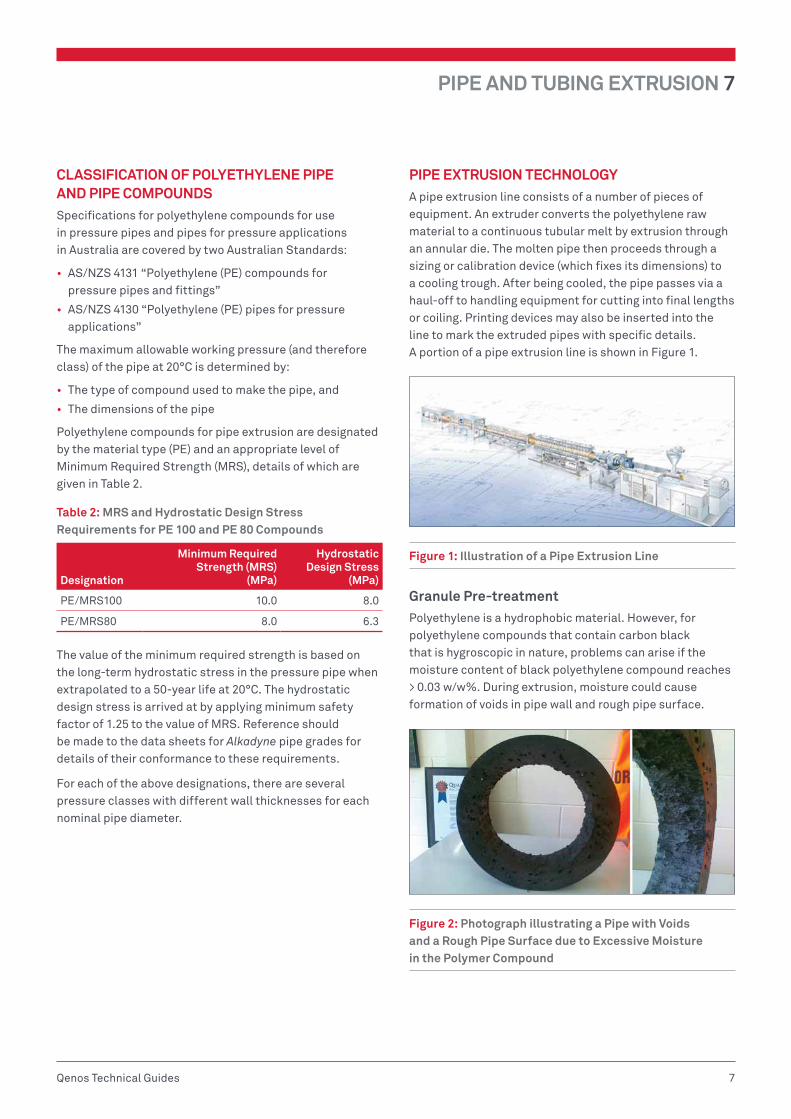
Granule Pre-treatmentPolyethylene is a hydrophobic material. However, for polyethylene compounds that contain carbon black that is hygroscopic in nature, problems can arise if the moisture content of black polyethylene compound reaches > 0.03 w/w%. During extrusion, moisture could cause formation of voids in pipe wall and rough pipe surface.
Figure 2: Photograph illustrating a Pipe with Voids and a Rough Pipe Surface due to Excessive Moisture in the Polymer Compound
7 PIPE AND TUBING EXTRUSION
8 Qenos Technical Guides
Such problems can be overcome by drying the polymer granules in a hopper dryer at 70 – 90°C for 1.5 – 2 hours immediately before feeding them into the extruder. The duration of drying and the drying temperature should be such that the moisture content is reduced to < 0.02 w/w%.
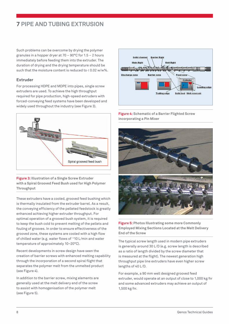
ExtruderFor processing HDPE and MDPE into pipes, single screw extruders are used. To achieve the high throughput required for pipe production, high-speed extruders with forced-conveying feed systems have been developed and widely used throughout the industry (see Figure 3).
Figure 3: Illustration of a Single Screw Extruder with a Spiral Grooved Feed Bush used for High Polymer Throughput
These extruders have a cooled, grooved feed bushing which is thermally insulated from the extruder barrel. As a result, the conveying efficiency of the pelleted feedstock is greatly enhanced achieving higher extruder throughput. For optimal operation of a grooved bush system, it is required to keep the bush cold to prevent melting of the pellets and fouling of grooves. In order to ensure effectiveness of the grooved zone, these systems are cooled with a high flow of chilled water (e.g. water flows of ~10 L/min and water temperature of approximately 10–20°C).
Recent developments in screw design have seen the creation of barrier screws with enhanced melting capability through the incorporation of a second spiral flight that separates the polymer melt from the unmelted product (see Figure 4).
In addition to the barrier screw, mixing elements are generally used at the melt delivery end of the screw to assist with homogenisation of the polymer melt (see Figure 5).
Figure 4: Schematic of a Barrier Flighted Screw incorporating a Pin Mixer
Figure 5: Photos Illustrating some more Commonly Employed Mixing Sections Located at the Melt Delivery End of the Screw
The typical screw length used in modern pipe extruders is generally around 30 L/D (e.g. screw length is described as a ratio of length divided by the screw diameter that is measured at the flight). The newest generation high throughput pipe line extruders have even higher screw lengths of 40 L/D.
For example, a 90 mm well designed grooved feed extruder, would operate at an output of close to 1,000 kg/hr and some advanced extruders may achieve an output of 1,500 kg/hr.

PIPE AND TUBING EXTRUSION 7
9Qenos Technical Guides
Table 3 shows expected specific screw output ranges (expressed as kg/hr/rpm) of pipe extruders versus screw diameter for high-speed-extruders with forced-conveying feed sections. Advanced extruders will have outputs close to the maximum of the designated output specification.
Table 3: LDPE and HDPE Specific Screw Output Data Versus Screw Diameter
Screw diameter mm
Specific output [kg/hr/rpm]
LDPE HDPE
45 0.4 – 0.6 0.5 – 0.8
60 0.9 – 1.2 1.2 – 1.7
75 1.8 – 2.4 2.5 – 3.0
90 3.0 – 4.0 4.0 – 5.0
120 6.0 – 8.0 8.0 – 11
150 10 – 13 12 – 16
The economics of a pipe production plant will depend on the following:
• The range of pipe sizes – e.g. diameter sizes
• The length of pipe runs – e.g. producing pipe of a set dimension
• The available length of the cooling unit in the production building
Bearing this in mind, increasing plant production capacity might not be as straight forward as installing larger and higher throughput extruders.
Pipe DiesToday, manufacturers of pipe extrusion lines supply pipe dies (see Figure 6) which they have developed themselves but which are essentially based on a common design principle.
Figure 6: Photograph of a Pipe Die
High production extruder throughput has resulted in the polymer experiencing low residence times in the extruder. This lack of residence time can lead to concerns about melt homogeneity and whether an even temperature distribution has been achieved throughout the melt. Modern pipe resin grades also have high melt viscosity and elasticity that are required for the strength of the final product, as well as for the ability to make large and thick walled pipes within dimensional tolerances respectively. These polymer features make the extrusion line die absolutely essential for the successful manufacture of pipe, especially with respect to its capacity to even up any melt inhomogeneity and shape it into the pipe without the generation of weld lines or any other memory effects which could potentially compromise the strength or appearance of the final product.
One of the established die designs is a “Spiral Mandrel“. The wide acceptance of this die has seen it incorporated into many new pipe production line designs. This die design has an excellent capability to homogenise melt and shape it into pipe without generating any imperfections which could compromise the final quality or integrity of the pipe (see Figures 7 and 8).
Figure 7: Schematic Diagram Detailing the Components of a Spiral Mandrel Die

7 PIPE AND TUBING EXTRUSION
10 Qenos Technical Guides
Figure 8: A Spiral Distributor and its Operating Principle for Melt Homogenisation
Another die design which has found wide approval and use in pipe manufacture, for its performance, is the Lattice-Basket type die. This design results in relatively low extrusion melt pressure and consequently relatively low melt temperature, both favourable for high extruder output (see Figure 9).
Figure 9: A Lattice-Basket Die and the Basket Part of the Die
Sizing and CoolingIn the state-of-the-art pipe manufacturing lines produced today, vacuum tank sizing is the predominant method used to shape the pipe from the melt. This includes the manufacture of the very largest pipes that have dimensions of 2000 mm. Unlike vacuum sizing, the internal pressure sizing method, where a positive pressure is built up within the pipe through the use of a floating plug, has been rapidly phased out due to safety concerns.
These concerns are associated with potential of building up excessive internal pressure within the pipe and leading to an uncontrolled rupture including release of the floating plug. Vacuum sizing technology enables quick starting up of an extrusion line. In addition, the melt emerging from the die can be drawn down to obtain a range of final pipe diameters so that it is possible to produce at least two standard pipe sizes with a single die/calibrator combination.
The pipe is shaped by a slotted sizing sleeve commonly referred to as a “calibrator”. The calibrator is placed at the entrance of the first vacuum tank and it is the first downstream piece of line that the polymer melt sees after having exited the die. Calibrators are usually made from non-ferrous metal for rapid removal of heat (see Figures 10 and 11). A film of water is fed to the inlet of the calibrator to enable rapid cooling (e.g. below the cyrstallisation temperature of the polymer) to solidify the external pipe layer in order to pull the pipe into the calibrator without tearing the molten tube apart. Water also acts as a lubricant to reduce frictional forces on the pipe’s surface whilst it is being pulled through the calibrator. The vacuum tank, in which the calibrator is placed, applies a vacuum which pulls the still hot, malleable tube against the wall of the calibrator, thereby setting the outer pipe diameter to ensure conformance to the pipe’s dimensional specification. The vacuum is operated at about 0.05 MPa, absolute pressure, which could vary depending on the pipe dimensions. The calibrator is usually 3 – 5% larger than the required final outer pipe diameter to provide for shrinkage which takes place during pipe cooling.
Figure 10: Sizing Sleeve for Vacuum-tank Sizing

PIPE AND TUBING EXTRUSION 7
11Qenos Technical Guides
Figure 11: Vacuum Tanks for Sizing Pipes up to 1,400 mm in Diameter
Downstream of the 1st vacuum tank there could be another vacuum tank and certainly more cooling tanks to ensure that the pipe completely solidifies by the time it gets to the saw (see Figure 12). The additional cooling is important to achieving the final pipe dimensions within the desired tolerances.
Figure 12: Photographs of Spray Water Bath
The length of the cooling zone is dependent on the output and the given dimensions of the pipe. The total length (L) of the required cooling zone, can be calculated on the assumption that a molten polymer extrudate, at a temperature of ~220oC, has to be cooled with water to an external pipe temperature of ~20oC, at which point the internal surface temperature of the pipe is a maximum of 85oC.
Using these assumed temperatures, the total cooling-zone length can be calculated as follows:
L = Lspec . Q (m)where Lspec = specific cooling-zone length
(m.hr/kg)
Q = output (kg/hr)
Lspec relative to the pipe dimension is outlined in Table 4 below:
Table 4: Lspec Relative to the Pipe Dimension
Pipe SDR* 41 33 26 17.6 11 7.4
Lspec for HDPE 0.016 0.02 0.024 0.036 0.06 0.08
* SDR = Standard Dimension Ratio; a nominal ratio of the pipe outside diameter to its wall thickness
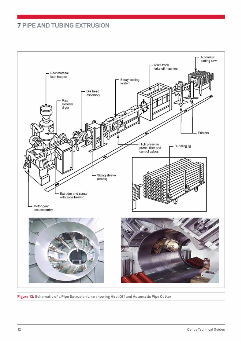
Downstream EquipmentDownstream equipment covers all other plant units besides the extruder, die, sizing and cooling systems (see Figure 13). Most pipe manufacturing lines will have:
• Ultrasonic Thickness Meter – that continuously measures the wall thickness around the circumference of the pipe
• Caterpillar Haul Off Unit – with concentrically arranged caterpillars held under pneumatic pressure against the pipe to transmit the haul-off forces. For start-ups, the haul-off unit can be switched to operate in the reverse to enable a pipe to be run back through the cooling and sizing systems to the point where the melt exits from the pipe die. There the pipe can be welded to the extrudate.
• Marking Unit – where the pipe is marked with standard specifications
• Automatically Adjustable Saw – mounted on a table cuts the pipe into the desired lengths
• Coiling Unit – where smaller diameter pipes can be wound into coils or onto reels up to the appreciable pipe size of 250 mm pipe diameter
7 PIPE AND TUBING EXTRUSION
12 Qenos Technical Guides
Figure 13: Schematic of a Pipe Extrusion Line showing Haul Off and Automatic Pipe Cutter
PIPE AND TUBING EXTRUSION 7
13Qenos Technical Guides
Process ControlIn new pipe production lines, process control computers are used to automate production.
To produce pipe in the required dimensions, the relevant operating data is entered, for example:
• Required throughput
• Pipe dimensions
• Screw speed
• Haul-off rate
The set-point values and permissible deviations are suitably fed-back to the controller for process data monitoring.
In pipe manufacture, material costs represent a substantial proportion of the overall costs of production. It is therefore advisable to use computerised process control for optimum production of pipes with the least possible waste of material and the best possible thickness uniformity around the pipe circumference. Figure 14 shows a schematic diagram of a computerized process control system for a pipe production line.
Figure 14: Computerized Process Control System for a Pipe Production Line
The most commonly employed control system operates on the basis of interaction between the following options:
• Weigh Feeder – the extruder is equipped with a weigh feeder. Weighed granule portions are fed to the extruder operating at required speed to achieve set off-take of the weighted granulate feed. Any deviation from the set output resulting from the constant weight feed is compensated for by speed adjustment of the extruder screw via the control system.
• Haul Off Control – the haul-off is set to a speed calculated from the specified output and the required weight per metre of the pipe. Pipe wall thickness is measured around the circumference with an ultrasonic wall thickness meter.
MECHANICAL PERFORMANCE OF POLYETHYLENE PIPE GRADES
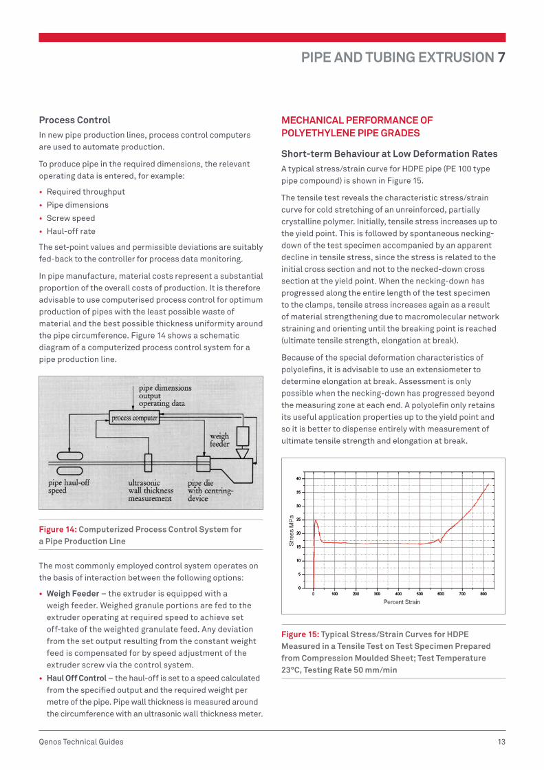
Short-term Behaviour at Low Deformation RatesA typical stress/strain curve for HDPE pipe (PE 100 type pipe compound) is shown in Figure 15.
The tensile test reveals the characteristic stress/strain curve for cold stretching of an unreinforced, partially crystalline polymer. Initially, tensile stress increases up to the yield point. This is followed by spontaneous necking-down of the test specimen accompanied by an apparent decline in tensile stress, since the stress is related to the initial cross section and not to the necked-down cross section at the yield point. When the necking-down has progressed along the entire length of the test specimen to the clamps, tensile stress increases again as a result of material strengthening due to macromolecular network straining and orienting until the breaking point is reached (ultimate tensile strength, elongation at break).
Because of the special deformation characteristics of polyolefins, it is advisable to use an extensiometer to determine elongation at break. Assessment is only possible when the necking-down has progressed beyond the measuring zone at each end. A polyolefin only retains its useful application properties up to the yield point and so it is better to dispense entirely with measurement of ultimate tensile strength and elongation at break.
Figure 15: Typical Stress/Strain Curves for HDPE Measured in a Tensile Test on Test Specimen Prepared from Compression Moulded Sheet; Test Temperature 23°C, Testing Rate 50 mm/min

7 PIPE AND TUBING EXTRUSION
14 Qenos Technical Guides
The effect of temperature on the yield stress, ultimate tensile strength and elongation at break of a typical HDPE pipe grade is shown in Figure 16.
Figure 16: Yield Stress, Ultimate Tensile Strength and Elongation at Break of HDPE as Functions of Temperature
Long-term BehaviourHigh density polyethylene is a viscoelastic material. Like all thermoplastics, it exhibits the property known as creep, i.e. over a period of time it undergoes deformation even at room temperature and under relatively low stress. After removal of stress, a moulding more or less regains its original shape, depending on the time under stress and the magnitude of the stress. The recoverable deformation is known as elastic deformation whereas the permanent deformation is called plastic deformation.
It should be remembered that the mechanical properties of a plastic are dependent on the three important parameters of time, temperature and stress.
In design calculations for moulded components, the mechanical property values (which in most cases are determined by long-term tests) must be divided by a safety factor.
Creep Behaviour Under Uniaxial StressA distinction is made between creep and relaxation tests.
Creep TestIn the creep test, the increase in deformation with time of a specimen held under a constant stress is measured and from this, the creep modulus is calculated.
Measurement can be carried out in a flexural creep test or a tensile creep test. It should be noted that the creep modulus is dependent on the level of stress as well as on temperature and time. Typical creep curves are shown in Figures 17 and 18.
Figure 17: Typical Tensile Creep Modulus Curves of HDPE Determined at 23°C
Figure 18: Typical Tensile Creep Modulus Curves of HDPE, Determined at 40°C
Similar tests have been carried out to determine creep moduli under compressive stress. Taking scatter into account, these gave approximately the same results as those for tensile stress.
The creep modulus can be used in design calculations for moulded parts which are to be exposed to constant stress over an extended period of time.

PIPE AND TUBING EXTRUSION 7
15Qenos Technical Guides
Relaxation TestIn the relaxation test, the stress decay with time of a specimen held under constant deformation is measured and from this, the relaxation modulus is calculated.
Figure 19: Typical Relaxation Modulus Curves of HDPE, Determined at 23°C
It should be noted that the relaxation modulus is dependent on the level of strain as well as on temperature and time.
The relaxation modulus (see Figure 19) can be used in design calculations for moulded parts that are to be exposed to constant strain or compression over an extended period of time.
Behaviour at High Deformation RatesInformation on the toughness characteristics of polymer materials at high deformation rates is provided by flexural and tensile impact strength tests. The results of impact strength tests (values for impact strength, notched impact strength and tensile impact strength) are considerably influenced by the conditions under which the test specimen is prepared. Injection moulded test specimens because of their rapid cooling rate are less crystalline when solid and therefore more impact resistant than those prepared from compression moulded sheet. The orientation produced by injection moulding also has an effect.
QUALITY TESTING OF POLYETHYLENE PIPE
PE 100: A Package of Good PropertiesThe designation PE 100 indicates that a PE-HD material has been assigned to performance class MRS 10 where MRS stands for Minimum Required Stress. The minimum creep strength is thus 10 MPa stress in the pipe wall at 20°C and 50 years. However creep strength alone does not determine assignment to material class 100 but rather a whole range of improved properties resulting from the much improved toughness of these materials, the most notable being:
• High resistance to Slow Crack Growth (SCG)
• High resistance to Rapid Crack Propagation (RCP)
Hydrostatic Pressure TestsUndoubtedly the most important property of plastic pipes is their hydrostatic strength behaviour under internal pressure or “Creep Strength”. This is what determines the service life expectancy of the pipe under internal pressure.
The equivalent stress (resulting from the action of the applied pressure within the pipe) corresponds in practice to the hoop stress acting on the pipe internal surface. Knowledge of the permissible stress for the material concerned forms the basis for designing a pipe under a given internal pressure using the calculation formula for pressure vessels.
The pressure to be used in the test is calculated from the equation below, knowing the dimensions of the pipe and the required hoop stress.
P = 2ST
Dm min. + T
where: P = maximum working pressure at 20oC (MPa)S = hoop stress of hydrostatic design stress at 20oC (MPa)T = minimum wall thickness (mm)Dm min. = minimum mean inside diameter (mm)
Creep Test Under Internal PressureThe stress that leads to rupture in plastic pipes depends on the time under stress and the temperature of the test. Creep behaviour has been studied in long-term tests over many years, in some cases, since 1956 (see Figure 20). ISO 9080 standard “Plastics piping and ducting systems —Determination of the long-term hydrostatic strength of thermoplastics materials in pipe form by extrapolation” sets out rules for the determination of the long-term hydrostatic strength of polyethylene pipes.

7 PIPE AND TUBING EXTRUSION
16 Qenos Technical Guides
Figure 20: The First Creep Rupture Test Started In 1956 In HOECHST (today known As Lyondell Basell) Laboratory, Frankfurt
The same test rig, and “original” pipes are still in operation today (see Figure 21). On 18th October 2006, two pipe specimens on this “historical“ test stand finally confirmed the predicted service of 50 years.
Figure 21: The First Creep Rupture Test Started in 1956 in HOECHST (today known as Lyondell Basell) Laboratory, Frankfurt, is still on test
The hydrostatic tests that are carried out on pipe sections under internal pressure take into account the effect of the multi-axial strain occurring in practice. The pipes are filled with water and suspended in a temperature-controlled environment such as a water bath (see Figure 22).
Figure 22: Extensive Hydrostatic Pipe Testing at Qenos Technical Centre

PIPE AND TUBING EXTRUSION 7
17Qenos Technical Guides
Pipe pressure Curve and Service Life ExtrapolationThe results of these tests are plotted on a log-log scale. Test stress is plotted against endurance time. After sufficiently long testing times, the typical pipe curve obtained from this plot shows three different regions or stages (see Figure 23).
Figure 23: Representation of Pipe Curve According to the 3-stage Model (Illustration by Studsvik Material AB now known as Exova)
Starting with short endurance times, a flat, straight branch can be seen which is followed by a straight, steep branch. With the PE 100 grades currently used, this steep branch does not begin for 10 000 hours, even at elevated temperature (e.g. 80°C). After very long endurance times, a vertical, stress-independent branch of the curve could be expected to follow for testing at 80°C, effectively indicating resin has degraded due to long exposure to high temperature.
Each of the three curve stages is associated with three different failure mechanisms. In the flat stage of the pressure curves at 20°C and 80°C represented on Figure 25, only ductile fractures are observed. Ductile type failure shows a visible deformation on the pipe in the failure region. Figure 24 shows a section of pipe that has failed in a ductile mode.
Figure 24: Pipe Failed in Ductile Mode
Ductile failure indicates ultimate pressure bearing capability of the pipe. The flat branch therefore marks the stress limit for ductile failure.
Figure 25: Qualitative Interpretation of Pipe Curve as Generated on PE 80 Pipe Grade. Testing was According to ISO 9080.
For the long-term properties of a pipe material, the position of the steep branch is crucial (e.g. in practice the steeper branch in the pressure test is referred to as a “knee”). It is determined by the resistance of the material to slow crack propagation. This material property, also referred to as brittle fracture resistance, determines the service life of the pipeline. In other words pipelines are designed to operate in a “ductile” failure regime. The inflection point (the transition between the flat and steep branches) can be observed, if at all, only at high temperature and after very long endurance times. This position denotes the transition from “ductile” to “brittle” type behaviour of pipe under pressure.
Pipe that has failed in a brittle mode doesn’t show visible ductility in the failure region (see Figure 26).

7 PIPE AND TUBING EXTRUSION
18 Qenos Technical Guides
Figure 26: Pipe Failed in Brittle Mode
Modern pipe grades such as PE 100 should not show “brittle” like pipe failures in hydrostatic tests, even at 80°C, within the required one year testing time (see Figure 27).
Figure 27: Creep Rupture Curve for Qenos PE 100 Grade Alkadyne HDF193B. Testing was According to ISO 9080.
When a PE piping system is to operate at a continuous temperature higher than “designated standard” temperature of 20°C, ISO 9080 analysis could be used to demonstrate capability of the pipe network in terms of extrapolated values for application stress and life time. Actual service life time of the PE pipe network will depend on application conditions and ISO 9080 extrapolation should not be used to infer actual service life time of the PE network.
TEMPERATURE RE-RATING OF PE PIPESThe Maximum Allowable Operating Pressure (MAOP) of a polyethylene (PE) pipe system is influenced by the temperature of the pipe wall. The nominal pressure rating (PN) assigned to an AS/NZS 4130 PE pipe equates to performance at 20°C, i.e. a PN16 pipe is capable of withstanding a MAOP of 160 m head (or 1.6 MPa or 16 bar pressure) when operating continuously at 20°C. However, as the temperature of the pipe wall increases, the MAOP of the pipe is reduced progressively, in other words the pipe system is re-rated with increasing temperature.
The guidance provided in this document is based on typical PE compounds used in Australia and New Zealand to manufacture AS/NZS 4130 PE pipe and listed in PIPA Guideline POP004, Polyethylene Pipe Compounds.
Note: These guidelines apply to pipe used for the conveyance of water. Where other incompressible fluids are being considered, the designer must assess the effect of the fluid on the PE pipe system at the operating temperature. For example internal fluids such as aggressive condensates when absorbed may have the effect of reducing the material strength upon which design stress is based.
The rerating factors in this guideline are expressed in terms of metre head of water and are not for use with compressed air or gas applications.
The following information details how to determine the temperature of the pipe wall and, then using Table 5 and 6, determine the de-rated MAOP value for the system. These recommendations are not to be taken as detailed specifications.
Determining the Temperature of the Pipe WallThe pressure rating of PE pressure pipe systems is based on the temperature of the pipe wall, which may be determined from either:
a. An assumption of a constant pipe wall temperature typical for continuous service at a set temperature, e.g. cold water service; or
b. The determination of an average service temperature where temperature variations are likely to occur in a predictable pattern (refer below), e.g. in cavity walls or roof spaces; or
c. The maximum service temperature less 10°C for installations where large unpredictable temperature variations occur up to a maximum of 80°C, e.g. above-ground installations such as irrigation systems.

PIPE AND TUBING EXTRUSION 7
19Qenos Technical Guides
Predictable Temperature VariationsFor installations where predictable temperature variations occur, the average material temperature is determined from Item (d) or Item (e) as follows:
d. Across the wall of the pipe — the material temperature taken as the mean of the internal and external pipe surface temperatures, where a temperature differential exists between the fluid in the pipe and the external environmental.
The pressure and temperature condition, where flow is stopped for prolonged periods, should also be checked. In this event, fluid temperature and outside temperature may equalise.
e. With respect to time — the average temperature may be considered as the weighted average of temperatures for the proportion of time spent at each temperature under operational pressures; it is calculated with the equation:
Tm = T1L1 + T2L2 + ... + TnLn
where:
Tm = average pipe material temperature for the period of time under consideration, in °C
Tn = average pipe material temperature for a proportion of pipe life, in °C
Ln = proportion of life spent at temperature Tn
Determining the MAOP ValueOnce the temperature of the pipe wall has been determined using any one of the methods (a), (b) or (c) above, the following tables can be used to determine the re-rated MAOP for the PE pipe system.
Table 5 nominates the corresponding MAOP for a given temperature for PE 80B material. Table 6 provides the same information for PE 100 material.
Table 5: Maximum Allowable Operating Pressure – PE 80
Temp (ºC)
Min Life (yr)
Design Factor PN 3.2 PN 4 PN 6.3 PN 8 PN 10 PN 12.5 PN 16 PN 20
20 100 1.0 32 40 64 80 102 128 160 200
25 1.0 32 40 64 80 102 128 160 200
30 1.2 27 33 53 67 85 107 133 167
35 1.3 25 31 49 62 78 98 123 154
40 1.3 25 31 49 62 78 99 123 154
45 1.4 23 29 46 57 73 91 114 143
50 36 1.6 20 25 40 50 63 80 100 125
55 24 1.7 19 24 38 47 60 75 94 118
60 12 1.8 18 22 36 44 56 71 89 111
80 1 2.4 13 17 27 33 42 53 67 83
Table 6: Maximum Allowable Operating Pressure – PE 100
Temp (ºC)
Min Life (yr)
Design Factor PN 4 PN 6.3 PN 8 PN 10 PN 12.5 PN 16 PN 20 PN25
SDR41 SDR26 SDR21 SDR17 SDR13.6 SDR11 SDR9 SDR7.4
20 100 1.0 40 64 80 100 127 160 200 250
25 100 1.1 36 58 73 91 115 145 182 227
30 100 1.1 36 58 73 91 115 145 182 227
35 50 1.2 33 53 67 83 106 133 167 208
40 50 1.2 33 53 67 83 106 133 167 208
45 35 1.3 31 49 62 77 99 123 154 192
50 22 1.4 29 46 57 71 91 114 143 179
55 15 1.4 29 46 57 71 91 114 143 179
60 7 1.5 27 43 53 67 85 107 133 167
80 1 2.0 20 32 40 50 63 80 100 125
Note: the minimum life periods may be considered to be the minimum potential service lives and represent the maximum extrapolated periods permitted by the ISO 9080 extrapolation rules given the available test data.
7 PIPE AND TUBING EXTRUSION
20 Qenos Technical Guides
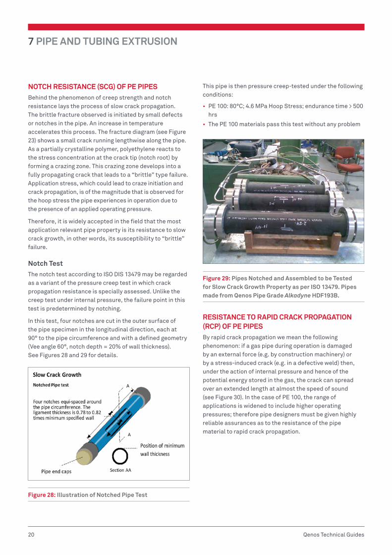
NOTCH RESISTANCE (SCG) OF PE PIPESBehind the phenomenon of creep strength and notch resistance lays the process of slow crack propagation. The brittle fracture observed is initiated by small defects or notches in the pipe. An increase in temperature accelerates this process. The fracture diagram (see Figure 23) shows a small crack running lengthwise along the pipe. As a partially crystalline polymer, polyethylene reacts to the stress concentration at the crack tip (notch root) by forming a crazing zone. This crazing zone develops into a fully propagating crack that leads to a “brittle” type failure. Application stress, which could lead to craze initiation and crack propagation, is of the magnitude that is observed for the hoop stress the pipe experiences in operation due to the presence of an applied operating pressure.
Therefore, it is widely accepted in the field that the most application relevant pipe property is its resistance to slow crack growth, in other words, its susceptibility to “brittle” failure.
Notch TestThe notch test according to ISO DIS 13479 may be regarded as a variant of the pressure creep test in which crack propagation resistance is specially assessed. Unlike the creep test under internal pressure, the failure point in this test is predetermined by notching.
In this test, four notches are cut in the outer surface of the pipe specimen in the longitudinal direction, each at 90° to the pipe circumference and with a defined geometry (Vee angle 60°, notch depth = 20% of wall thickness). See Figures 28 and 29 for details.
Figure 28: Illustration of Notched Pipe Test
This pipe is then pressure creep-tested under the following conditions:
• PE 100: 80°C; 4.6 MPa Hoop Stress; endurance time > 500 hrs
• The PE 100 materials pass this test without any problem
Figure 29: Pipes Notched and Assembled to be Tested for Slow Crack Growth Property as per ISO 13479. Pipes made from Qenos Pipe Grade Alkadyne HDF193B.
RESISTANCE TO RAPID CRACK PROPAGATION (RCP) OF PE PIPESBy rapid crack propagation we mean the following phenomenon: if a gas pipe during operation is damaged by an external force (e.g. by construction machinery) or by a stress-induced crack (e.g. in a defective weld) then, under the action of internal pressure and hence of the potential energy stored in the gas, the crack can spread over an extended length at almost the speed of sound (see Figure 30). In the case of PE 100, the range of applications is widened to include higher operating pressures; therefore pipe designers must be given highly reliable assurances as to the resistance of the pipe material to rapid crack propagation.

PIPE AND TUBING EXTRUSION 7
21Qenos Technical Guides
Figure 30: Example of Rapid Crack Propagation Fracture in Pipe Which Shows the Actions of Residual Stresses on the Cracked Pipe During RCP
S4 TestCommonly employed testing methodology for RCP is based on the ISO 13477 standard. It is known in industry as the S4 test (small-scale, steady-state test). The S4 test is carried out as follows: a weight with a knife attached to the end is dropped onto a pipe of standardised length and under a constant internal gas pressure near one of its ends to produce a rapidly progressing axial crack. The crack initiation process should damage the pipe as little as possible. The term crack propagation is used if the crack length, a, is greater than or equal to 4.7 dn (4.7 times the nominal outside diameter). See Figures 31 and 32 for details.
Figure 31: Schematics of a Test Rig for the S4 Test
Figure 32: Actual Test Rig for the S4 Test
A series of tests at 0°C but varying in testing pressure lead to the determination of the critical pressure at which there is a sharp transition from abrupt arrest of the initial crack to continued, steady-state, crack propagation. This method arrives at the “Critical Pressure” at which RCP occurs.
Alternatively, tests can be carried out at the set pressure but varying test temperatures to determine the “Critical Temperature” at which RCP occurs (see Tables 7 and 8).
In designing a pipeline, to carry gas at high pressure or at sub-zero temperatures the RCP property of pipe resin needs to be considered and a safety factor must be taken into account.
For gas pipelines made from Qenos Alkadyne PE 100 grades, the high RCP property ensures safe pipe line operation at high operating pressures as well as sub-zero temperatures.

7 PIPE AND TUBING EXTRUSION
22 Qenos Technical Guides
Table 9: Collation of ISO to Australian Standards for Set Items, Equipment, Installation and Testing
International Standard Subject Matter Australian Standard
ISO 8085-2 Fittings AS/NZS4129 Section 6
ISO 4437 Gas Pipe AS/NZS4130
ISO 4427 Water Pipe AS/NZS4130
ISO 12176-1 Equipment Not applicable
ISO/TS 10839 Installation AS/NZS2033, AS/NZS 4645
ISO 13593 Tensile Test Not applicable
ISO 1167-1 Hydrostatic Pressure Test AS/NZS 4130 Clause 10.1
ISO 1167-3 Hydrostatic Pressure Test AS/NZS 4130 Clause 10.1
ISO 1167-4 Hydrostatic Pressure Test AS/NZS 4130 Clause 10.1
ASTM F2634 High speed tensile test Not applicable
Table 7: RCP Testing of PE 100 Pipe at a Fixed Pressure and Varying Temperature
Pipe No.Temperature
(°C)Pressure
(MPa)Crack Length
lC (mm) lC /dn Results
1 -5 0.5 120 1.1 Crack Arrest
2 -10 0.5 135 1.2 Crack Arrest
3 -15 0.5 165 1.5 Crack Arrest
4 -20 0.5 360 3.3 Crack Arrest
5 -25 0.5 300 2.7 Crack Arrest
The critical temperature Tc of the PE pipes (110 mm diameter) SDR11, Qenos grade Alkadyne HDF145B, at a pressure of 0.5 MPa, is lower than or equal at -25°C
Table 8: RCP Testing of PE 100 Pipe at a Fixed Temperature and Varying Pressure
Pipe No.Pressure
(MPa)Crack Length a
(mm) a/dn Results
1 0.0 85 0.8 Initiation Test
2 0.4 110 1.0 Crack Arrest
3 0.6 120 1.1 Crack Arrest
4 0.8 130 1.2 Crack Arrest
5 1.0 125 1.1 Crack Arrest
The critical pressure Pc,S4 of the PE pipes (110 mm diameter) SDR11, Qenos grade Alkadyne HDF145B, at a temperature of 0°C, is higher than or equal to 1.0 MPa

PIPE AND TUBING EXTRUSION 7
23Qenos Technical Guides
JOINING PE PIPES
Butt fusion jointing of PE pipes and fittingsNote: Information is based on POP 003 prepared by PIPA (Polyolefin Industry Pipe Association) as a guide to the butt fusion of polyethylene pipe using AS/NZS 4130 material as a basis.
Relevant StandardsThe butt fusion procedures and parameters are specified in ISO 21307, Plastics pipes and Fittings – Butt Fusion Jointing Procedures for Polyethylene (PE) Pipes and Fittings Used in Construction of Gas and Water Distributions Systems.
ISO 21307 specifies three proven butt fusion jointing procedures for pipes and fittings with a wall thickness up to and including 70 mm, taking into consideration:
• The materials and components used
• The fusion jointing procedure and equipment
• The quality assessment of the completed joint
This standard also covers the weld procedure for activities such as surface preparation, clamping, alignment and cooling procedures.
Where ISO 21307 references other International Standards, the equivalent Australian Standard is deemed to apply. Where there is no equivalent Australian Standard then the International Standard applies (see Table 9).
Jointing ProceduresButt welding involves the heating of two pipe ends to fusion temperature and then subsequently joining the two ends by the application of force. However, a successful butt weld requires the correct combination and sequence of the welding parameters time, temperature and pressure.
Various proven butt fusion methods with minor differences have been in use in different countries for many years. ISO 21307 contains three distinct fusion methods described below for pipe and fittings with a wall thickness up to and including 70 mm.
It is essential that the parameters specified for a given method are followed. Do not mix and match parameters from each method.
• Single pressure – low fusion jointing pressure This method has been used by most European countries and in Australia. The single pressure parameters specified are very similar to those previously specified by PIPA. Welders familiar with those parameters will adapt easily to the ISO Single pressure – low fusion jointing method.
• Dual pressure – low fusion jointing pressure This method is used by the water industry in the UK, and in Europe for pipes with a wall thickness greater than 20 mm. These parameters are not commonly used in Australia.
• Single pressure – high fusion jointing pressure This method has been used extensively in Northern America. The weld interface pressure is approximately three times the low pressure method and, as a consequence, more of the molten material is extruded from the weld zone, thereby enabling a reduced cooling time. Extra attention is required to ensure that:
1. Welding machines have sufficient structural strength and hydraulic capacity to achieve the high pressure parameters in a safe manner. Confirmation should be sought from the machinery manufacturer.
2. The welding operator is sufficiently experienced and proficient with the parameters.
Where the pipe or fitting wall thickness exceeds 70 mm welding parameters should be agreed between the asset owner and the installer. Under these circumstances the pipe and fitting supplier and the equipment supplier should also be consulted.
Schematically all three welding procedures are outlined in Figure 33 and Table 10 which show:
• Procedures are similar in overall approach, i.e. the seven steps of fusion
• Primary differences are in applied pressure and approach to cooling
• When properly performed, all methods result in reliable joints
Initial Bead Up
Fusi
on P
ress
ure,
MP
a
Heat Soak
Bead Roll Over0.517 Mpa
0.15 Mpa
0.025 Mpa
TimeTime to achieveInterface FusionPressure
Heater Plateremoved
Dual Pressure European Single Pressure USA Single High Pressure
Cooling Time
Figure 33: Schematic Diagram of the Various Stages of the Polymer Butt Welding Process

7 PIPE AND TUBING EXTRUSION
24 Qenos Technical Guides
Table 10: Parameters Corresponding to the Three Butt Welding Processes
Butt Welding Parameter Unit Single Low Pressure Single High PressureDual Low Pressure (If en > 20mm)
Heater pipe temperature °C 200 to 245 200 to 230 225 to 240
P1 Bead up pressure MPa 0.17 ± 0.02 0.52 ± 0.1 0.15 ± 0.02
T1 Bead up time Visual First indication of melt everywhere around pipe. (Approx. 1mm, maximum 6mm)
P2 Heat soak pressure MPa 0 to drag pressure 0 to drag pressure 0 to drag pressure
T2 Heat soak time Seconds (11 ± 1)en (11 ± 1)en 10en + 60
Maximum bead size after T2 Mm 0.5 + 0.1en 0.15en + 1 0.5 + 0.1en
T3 Maximum heater plate removal time Seconds 0.1en + 4 0.1en + 8 ≤10
T4 Maximum time to achieving welding pressure
Seconds 0.4en + 2 0.1en + 8 ≤10
P3 Fusion jointing pressure Seconds 0.17 ± 0.02 0.52 ± 0.1 0.15 ± 0.02
T5 Cooling time Minutes en + 3 0.43en
T5a Fusion jointing time Seconds 10 ± 1
T5b Minimum cooling time in machine under reduced pressure
Minutes See ISO 21307
P4 Cooling cycle reduced pressure MPa 0.025 ± 0.002
T6 Additional cooling time Minutes Additional cooling time out of the machine and before rough handling or installation may be recommended, but in most cases is not necessary
Electrofusion Jointing of PE Pipes and FittingsNote: Information is based on POP 001 prepared by PIPA (Polyolefin Industry Pipe Association) as a guide to the electrofusion of polyethylene pipes and fittings complying with Australian/New Zealand Standards AS/NZS 4130 and AS/NZS 41291.
These guidelines set out the principal requirements for equipment, jointing procedures, maintenance, servicing and calibration of equipment, records and training for jointing by socket electrofusion (EF) and saddle electrofusion.
The guidelines are also applicable to electrofusion fittings that are available in the size range DN16 to DN800. Development work is being undertaken for larger sized electrofusion fittings.
To consistently make satisfactory joints it is important to follow the jointing procedure with particular emphasis on pipe surface preparation, avoidance of contamination, and machine calibration, as well as temperature control.
Pipes and fittings of different SDR can be joined together by the electrofusion process, e.g. DN250 SDR11 pipe can be successfully electrofused using a DN250 SDR17 fitting. Electrofusion fittings for pressure applications are usually
recommended for use with PE pipes SDR17 or lower (i.e. increased wall thickness).
Pipes of different PE materials- PE 63, PE 80 and PE 100 can also be jointed successfully using electrofusion sockets, provided that all components have adequate nominal pressure rating for the operating conditions and the PE materials comply with AS/NZS 4131.
Some manufacturers supply electrofusion fittings for thinner pipes, down to SDR33 whereas others limit the use of some saddle type fittings to SDR11 or thicker. These limitations are usually detailed on the fitting body or on the packaging. If in doubt, check with the supplier or manufacturer, as unsatisfactory joints are likely to occur if the fitting/pipe combination is incorrect.
It is recommended to refer to the supplier or manufacturer of the electrofusion fittings for the installation instructions, as the method may be specific to the fitting geometry.
Accurate record keeping and manual or automatic electrofusion equipment that provides good control of jointing conditions are essential.
1. EF fittings can be used with non-pressure drainage pipes made to AS/NZS 4401 and AS/NZS 5065.
PIPE AND TUBING EXTRUSION 7
25Qenos Technical Guides
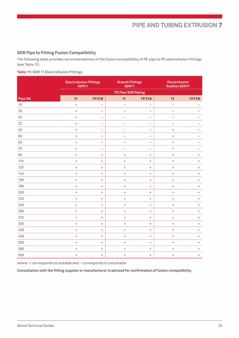
SDR Pipe to Fitting Fusion CompatibilityThe following table provides recommendations of the fusion compatibility of PE pipe to PE electrofusion fittings (see Table 11).
Table 11: SDR 11 Electrofusion Fittings
Pipe DN
Electrofusion Fittings SDR11
Branch Fittings SDR11
Electrofusion Saddles SDR11
PE Pipe SDR Rating
11 17/17.6 11 17/17.6 11 17/17.6
16 + – – – – –
20 + – – – – –
25 + – – – – –
32 + – – – – –
40 + – – – + –
50 + – – – + –
63 + – – – + –
75 + – – – + –
90 + + + + + +
110 + + + + + +
125 + + + + + +
140 + + + + + +
160 + + + + + +
180 + + + + + +
200 + + + + + +
225 + + + + + +
250 + + + + + +
280 + + + + + +
315 + + + + + +
355 + + + + + +
400 + + + + + +
450 + + + + + +
500 + + + + + +
560 + + + + + +
630 + + + + + +
where: + corresponds to suitable and – corresponds to unsuitable
Consultation with the fitting supplier or manufacturer is advised for confirmation of fusion compatibility.

7 PIPE AND TUBING EXTRUSION
26 Qenos Technical Guides
Electrofusion socket jointingElectrofusion socket jointing incorporates an electrical resistance element in the socket of the fitting which, when connected to an appropriate power supply, melts and fuses the materials of the pipe and fitting together.
The effectiveness of this technique depends on attention to preparation of the jointing surfaces, in particular the removal of the oxidised surface of the pipe over the socket depth, ensuring the jointing surfaces are clean and free
from contamination, and that the assembly and clamping instructions are correctly followed.
The pipe is prepared for jointing by removing a layer, maximum of 0.2 mm for pipes up to DN25, 0.2 mm to 0.3 mm for pipes up to DN75 and 0.2 mm to 0.4 mm for pipes larger than DN75. The minimum allowable outside diameter of the prepared pipe is shown below (see Table 12).
Table 12: DN of Pipe Versus Minimum Outside Diameter of Prepared Pipe
DN of Pipe
Minimum outside diameter (OD)
of prepared pipe (mm) DN of Pipe
Minimum outside diameter (OD)
of prepared pipe (mm)
16 15.6 200 199.2
20 19.6 225 224.2
25 24.6 250 249.2
32 31.4 280 279.2
40 39.4 315 314.2
50 49.4 355 354.2
63 62.4 400 399.2
75 74.4 450 449.2
90 89.2 500 499.2
110 109.2 560 559.2
125 124.2 630 629.2
140 139.2 710 709.2
160 159.2 800 799.2
180 179.2
If entry of the pipe or fitting spigot into an electrofusion coupling is still restricted after the oxidised layer has been removed, the pipe can be scraped down to the permissible minimum outside pipe diameter as in the above table. In this case, the thickness removed may be greater than the thickness stated above.
Pipe should also be checked for out-of-roundness (ovality). Some coiled pipes may be too oval to fit into electrofusion sockets and must be re-rounded with rounding tools or clamps to enable sockets to be fitted.
The equipment and procedures described below relate to fittings with centre stops. If fittings without centre stops are used, the maximum insertion depth should be clearly marked on the pipe ends after the pipe surface has been prepared and cleaned prior to jointing.
Equipment1. Control BoxThe control box input supply should be from a nominal 240V generator suitable to drive inductive loads and phase cut systems, commonly of about 5kVA capacity. Some fitting suppliers may consider smaller capacity generators acceptable for small diameter fittings. The nominal output of the generator should be 240V ± 10%, between no load and full load.
It should be noted that electrofusion control boxes may generate considerable heat. Refer to the supplier of the controller to ensure the box has an integrated cooling system.

PIPE AND TUBING EXTRUSION 7
27Qenos Technical Guides
Control boxes should include safety devices to prevent voltages greater than 42V AC for a 40V system being present at the control box output. The safety device should operate in less than 0.5 sec.
2. Peeling ToolsRotational peeling tools must be capable of removing a continuous and uniform chip thickness from the outer oxidised surface, over the required insertion depth, when preparing the fusion zone.
Hand scrapers are difficult to use, and effective preparation is time consuming, physically demanding and in most cases does not produce uniform scraping. Therefore rotational scrapers or peeling tools are preferred when welding occurs at pipe ends (see Figure 34).
Figure 34: Rotational Peeling Tool Used to Prepare Pipe Ends
3. Re-rounding and Alignment ClampsRe-rounding and alignment clamps or other approved methods have to be used for restraining, aligning and re-rounding pipes during the fusion cycle (see Figure 35a and b).
The benefits of alignment clamps are that they:
• Allow for re-rounding of pipes, particularly coiled pipes that are oval
• Provide correct assembly and alignment of the pipe with the fitting
• Enable the joint to be stabilised during the welding heating and cooling cycle
• Are stress free joints
• Have uniform melt pressure within the joint
Figure 35a: Re-rounding and Alignment Clamp Assembly used for Wide Bore Pipe
Figure 35b: In-field Laying of Multi-Jointed Pipe

7 PIPE AND TUBING EXTRUSION
28 Qenos Technical Guides
4. Pipe CuttersPipe cutters are mounted instruments that are used for the accurate cutting of pipes to ensure uniform and perpendicular pipe end. Such cutting devices should include the saw and saw guide (see Figures 36a and b).
Figure 36a: Examples of a Guillotine
Figure 36b: Motorised Hand Circular Saw Cutter
5. Weather ShelterSuitable shelter should be used to provide shade and protection for the pipe, fittings and equipment against adverse weather conditions and contamination of the jointing surfaces by dust and/or moisture, which can result in unsatisfactory joints. Fittings should only be removed from their original packaging immediately before using for jointing.
Electrofusion Jointing Method
Preparation of Pipe Endsi. Ensure hands and tools are free from surface
contaminants, such as barrier hand cream, sun screen, detergent and surfactant used in horizontal directional drilling.
ii. Check equipment is complete, clean, undamaged, in working order and protected by shelter.
iii. Ensure there is sufficient space to permit access to the jointing area. In a trench, a minimum clearance of 150 mm is required all round. Larger clearances may be needed for large nominal pipe sizes, depending on the tool used.
iv. Check that the pipe ends to be jointed are cut square to the axis and any burrs and swarf are removed.
v. Clean the fitting bore, followed by the pipe surface with a new approved alcohol wipe to remove traces of dirt, mud and other contamination. When using slip couplings clean the entire area where the fitting will pass over the pipe. The area of the pipe to be fusion jointed may be washed with clean water if necessary and dried with lint free material prior to peeling. Ensure the fusion area is completely dry before proceeding (see Figure 37). Do not use detergent or surfactants to clean pipe surfaces.
NOTE: Refer to fitting supplier for recommended alcohol wipes. Personal cleaning wipes may contain lanolin and detergent and are not to be used in electrofusion.
vi. Check ovality as described above and use re-rounding tools as appropriate.
With the fittings still in the bag, place alongside the pipe end and put a witness mark on the pipe at half the fitting length plus about 40 mm to enable visual checking of the scraped area after jointing is complete.
NOTE: Do not remove the fitting from its packaging at this stage.
vii. Check that the pipe clamps are of the correct size for the pipes to be jointed. Only use the correct size pipe clamps.
viii. Check the peeling tools are clean of dirt or other contaminants prior to use.
x. Using an appropriate peeling tool, remove the entire surface of the pipe to the depth of the witness mark. Metal files, rasps, emery paper, etc. are not suitable end preparation tools and should not be used.
xi. Mechanical peeling tools are strongly preferred, as they achieve a consistent pipe surface preparation. Hand scraping, particularly for larger diameter pipes, is time consuming and onerous to adequately prepare a complete pipe end.
PIPE AND TUBING EXTRUSION 7
29Qenos Technical Guides
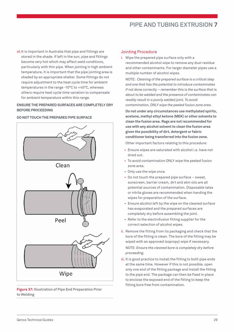
xii. It is important in Australia that pipe and fittings are stored in the shade. If left in the sun, pipe and fittings become very hot which may affect weld conditions, particularly with thin pipe. When jointing in high ambient temperature, it is important that the pipe jointing area is shaded by an appropriate shelter. Some fittings do not require adjustment to the heat cycle time for ambient temperatures in the range -10°C to +45°C, whereas others require heat cycle time variation to compensate for ambient temperature within this range.
ENSURE THE PREPARED SURFACES ARE COMPLETELY DRY BEFORE PROCEEDING
DO NOT TOUCH THE PREPARED PIPE SURFACE
Figure 37: Illustration of Pipe End Preparation Prior to Welding
Jointing Procedurei. Wipe the prepared pipe surface only with a
recommended alcohol wipe to remove any dust residue and other contaminants. For larger diameter pipes use a multiple number of alcohol wipes.
NOTE: Cleaning of the prepared surface is a critical step and one that has the potential to introduce contaminates if not done correctly – remember this is the surface that is about to be welded and the presence of contaminates can readily result in a poorly welded joint. To avoid contamination, ONLY wipe the peeled fusion zone area.
Do not under any circumstances use methylated spirits, acetone, methyl ethyl ketone (MEK) or other solvents to clean the fusion area. Rags are not recommended for use with any alcohol solvent to clean the fusion area given the possibility of dirt, detergent or fabric conditioner being transferred into the fusion zone.
Other important factors relating to this procedure:
• Ensure wipes are saturated with alcohol i.e. have not dried out.
• To avoid contamination ONLY wipe the peeled fusion zone area.
• Only use the wipe once.
• Do not touch the prepared pipe surface – sweat, sunscreen, barrier cream, dirt and skin oils are all potential sources of contamination. Disposable latex or nitrile gloves are recommended when handing the wipes for preparation of the surface.
• Ensure alcohol left by the wipe on the cleaned surface has evaporated and the prepared surfaces are completely dry before assembling the joint.
• Refer to the electrofusion fitting supplier for the correct selection of alcohol wipes.
ii. Remove the fitting from its packaging and check that the bore of the fitting is clean. The bore of the fitting may be wiped with an approved isopropyl wipe if necessary.
NOTE: Ensure the cleaned bore is completely dry before proceeding.
iii. It is good practice to install the fitting to both pipe ends at the same time. However if this is not possible, open only one end of the fitting package and install the fitting to the pipe end. The package can then be fixed in place to enclose the exposed end of the fitting to keep the fitting bore free from contamination.

7 PIPE AND TUBING EXTRUSION
30 Qenos Technical Guides
iv. Inscribe an accurate witness mark or insertion depth onto the pipe and then insert the pipe ends into the fitting so that they are in contact with the centre stop and witness mark. It is critical that the pipe be fully inserted, particularly for larger pipes or when there is no centre stop. Ensure an aligned pipe arrangement in order to avoid any stress during the jointing process, especially when using coiled pipes.
v. The pipe end(s) and the fitting must be correctly aligned and free of any bending stress. Use pipe clamps, or other suitable means, to secure the pipe(s) so they cannot move and ensure that the fitting is satisfactorily supported to prevent it sagging during the fusion procedure (see Figure 38).
Figure 38: Illustration of Pipe Clamps and Fitting Attached to Pipe Ends Prior to Welding
vi. Check that there is sufficient fuel for the generator to complete the joint. Start the generator and check that it is functioning correctly.
NOTE: Ensure the generator is switched on and running satisfactorily before connecting the electrofusion control box to the power source.
vii. Switch on the control box. Check that the reset button, if fitted, is in the correct mode.
viii. Connect the control box output leads to the fitting terminals and check that they have been fully inserted (see Figure 39).
ix. The jointing time is generally indicated either on the fitting or on a data carrier supplied with the fitting. Check that the correct time is shown on the control box display. If required for the control box, enter the fusion jointing time into the control box timer.
NOTE: Automatic control boxes are available which obviate the need to enter the fusion time.
x. If the control box is equipped with a barcode reader or barcode scanner, scan the fusion data barcode into the machine to ensure a fully automated and controlled data entry. Barcode reading control boxes automatically adjust for variable temperature conditions. For manual input of the heat fusion time into the control box, refer to the manufacturer’s parameters, supplied with the fitting.
Figure 39: Attachment of Control Box Leads to Pipe Fitting
xi. Press the start button on the control box and check that the heating cycle is proceeding as indicated by the display.
xii. On completion of the heating cycle, both melt indicators within the processed part of the fitting should have risen. If there is no apparent movement of either indicator the joint could be unsatisfactory (see Figure 40) – refer to discussion on electrofusion indicator pins below.
Figure 40: Diagram illustrating Locating of Melt indicators

PIPE AND TUBING EXTRUSION 7
31Qenos Technical Guides
xiii. If the fusion cycle terminates before completion of the countdown, check for faults as indicated by the control box warning lights or display. Check for a possible cause of the break, e.g. inadequate fuel in the generator, or power supply failure, etc.
NOTE: Do not attempt a second fusion cycle until the entire fitting has cooled to less than 45°C. Some manufacturers recommend replacement of the fitting rather than a second fusion cycle. Refer to the fitting manufacturer for details.
xiv. The completed joint should be left in the clamps for cooling. The time needed will be specified on the fitting, or by its data carrier, or in the display of the automatic control box.
xiv. When the joint has cooled, remove it from the clamps and inspect.
Electrofusion Indicator PinsThe fusion indicator protrusion following the completion of the fusion process indicates that fusion pressure has developed but does not guarantee the quality of the joint. The height of the extended pin is dependent upon the fitting in use, component tolerances and the pipe material.
The pins are used as a pointer to whether a more detailed inspection of the joint is required so in the event that the pin does not rise, the supervisor or operator must investigate the following to determine if the joint is satisfactory.
• Dimensional check and compliance of the pipe spigot OD and ovality.
• The fitting socket internal diameter by measurement or batch traceability.
• In the case where the pipe and socket are concentric, the maximum gap between the two should not exceed 1% of the nominal diameter. If the socket and spigot are eccentric the gap should not exceed 2%.
• That there is no disruption to the input power supply from the fusion box with no control box error messages.
• That the heat fusion parameters are correct.
• The pipe to fitting alignment is correct with no visible plastic extruded out from the fitting.
Maintenance, Servicing and CalibrationAll equipment should be well maintained and kept in a clean condition at all times.
The equipment should be serviced and calibrated regularly. The frequency at which this is carried out will be different for individual items of equipment and will also depend on usage, but should be at least once every 12 months. Guidance should be sought from the equipment manufacturer and a scheme of calibration and servicing should be implemented. Particular attention should be given to the control box, the generator and the scraping (or peeling) tools. The sharpness of the cutter head of the tools should be checked at least on a monthly base.
Records1. Job SupervisionElectronic or written records of appropriate fusion procedure for each joint should be kept as required.
2. Equipment Servicing and CalibrationElectronic or written records of appropriate servicing and calibration should be kept. The minimum information to be recorded is given in Appendix 1.
3. TrainingInstructions should be provided by Registered Training Organisations (RTO’s) that are accredited by State/Territory Training Authorities under the Australian National Training Authority (ANTA) guidelines and complying with PMB 01– Competency Standards prepared by Manufacturing Learning Australia, Qualification Framework for the plastics, rubber and cable making industry.
The RTO’s providing training in all forms of welding plastics pipeline systems must have staff qualified in presenting courses that meet competency standards covered by sections PMBWELD301A through to PMBWELD311A in PMB 01.
The RTO’s normally issue an accreditation certificate to successful candidates completing the training course and maintain a register of accredited welders.
7 PIPE AND TUBING EXTRUSION
32 Qenos Technical Guides
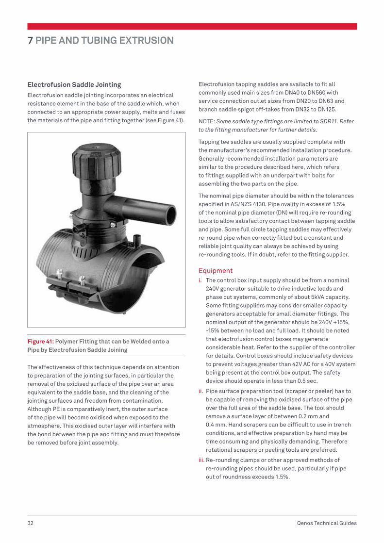
Electrofusion Saddle JointingElectrofusion saddle jointing incorporates an electrical resistance element in the base of the saddle which, when connected to an appropriate power supply, melts and fuses the materials of the pipe and fitting together (see Figure 41).
Figure 41: Polymer Fitting that can be Welded onto a Pipe by Electrofusion Saddle Joining
The effectiveness of this technique depends on attention to preparation of the jointing surfaces, in particular the removal of the oxidised surface of the pipe over an area equivalent to the saddle base, and the cleaning of the jointing surfaces and freedom from contamination. Although PE is comparatively inert, the outer surface of the pipe will become oxidised when exposed to the atmosphere. This oxidised outer layer will interfere with the bond between the pipe and fitting and must therefore be removed before joint assembly.
Electrofusion tapping saddles are available to fit all commonly used main sizes from DN40 to DN560 with service connection outlet sizes from DN20 to DN63 and branch saddle spigot off-takes from DN32 to DN125.
NOTE: Some saddle type fittings are limited to SDR11. Refer to the fitting manufacturer for further details.
Tapping tee saddles are usually supplied complete with the manufacturer’s recommended installation procedure. Generally recommended installation parameters are similar to the procedure described here, which refers to fittings supplied with an underpart with bolts for assembling the two parts on the pipe.
The nominal pipe diameter should be within the tolerances specified in AS/NZS 4130. Pipe ovality in excess of 1.5% of the nominal pipe diameter (DN) will require re-rounding tools to allow satisfactory contact between tapping saddle and pipe. Some full circle tapping saddles may effectively re-round pipe when correctly fitted but a constant and reliable joint quality can always be achieved by using re-rounding tools. If in doubt, refer to the fitting supplier.
Equipmenti. The control box input supply should be from a nominal
240V generator suitable to drive inductive loads and phase cut systems, commonly of about 5kVA capacity. Some fitting suppliers may consider smaller capacity generators acceptable for small diameter fittings. The nominal output of the generator should be 240V +15%, -15% between no load and full load. It should be noted that electrofusion control boxes may generate considerable heat. Refer to the supplier of the controller for details. Control boxes should include safety devices to prevent voltages greater than 42V AC for a 40V system being present at the control box output. The safety device should operate in less than 0.5 sec.
ii. Pipe surface preparation tool (scraper or peeler) has to be capable of removing the oxidised surface of the pipe over the full area of the saddle base. The tool should remove a surface layer of between 0.2 mm and 0.4 mm. Hand scrapers can be difficult to use in trench conditions, and effective preparation by hand may be time consuming and physically demanding. Therefore rotational scrapers or peeling tools are preferred.
iii. Re-rounding clamps or other approved methods of re-rounding pipes should be used, particularly if pipe out of roundness exceeds 1.5%.

PIPE AND TUBING EXTRUSION 7
33Qenos Technical Guides
iv. A pipe clamp of suitable dimensions for making the service or branch connection is needed.
v. Pipe cutters should include a saw and saw guide.
vi. Suitable shelter should be used to provide adequate protection for pipe, fittings and equipment against adverse weather conditions and contamination of the jointing surfaces by dust and/or moisture, which can result in unsatisfactory joints. Fittings should only be removed from their original packaging immediately before using for jointing.
Preparationi. Ensure hands and tools are free from surface
contaminants, such as barrier hand cream, sun screen, detergent and surfactant used in horizontal directional drilling.
ii. Expose the pipe onto which the tapping tee or saddle is to be assembled, ensuring there is clear space around the pipe. In a trench a minimum clearance of 150 mm is required all round. Larger clearances may be needed for larger nominal sizes, depending on the tool used.
iii. Wipe the joint area, where the saddle is to be fitted, with alcohol wipes to remove traces of dirt, mud and other contamination. The joint area may be washed with clean water if necessary and dried with lint free material prior to scraping. Ensure the joint surface is completely dry before proceeding. Do not use detergent or surfactants to clean pipe surfaces.
NOTE: Refer to fitting supplier for recommended alcohol wipes. Personal cleaning wipes may contain lanolin and detergent and are not suitable for use in electrofusion.
iv. Without removing the fitting from its packaging, place it over the required position on the pipe. Mark the pipe surface outlining the saddle base area plus about 20 mm with a suitable marker pen to allow for visual checking of the scraped area after jointing is complete.
v. Check ovality as described above and use re-rounding tools as appropriate.
vi. Using an appropriate preparation tool remove the entire surface of the pipe over the full area marked. If hand scrapping, ensure long even scrapes starting outside the marked area to ensure craters do not occur in the fusion zone, which can produce an excessive gap leading to a brittle weld. Remove the swarf. Metal files, rasps, emery paper, etc. are not suitable scraping tools and should not be used.
vii. It is important in Australia that pipe and fittings are stored in the shade. If left in the sun the pipe and fittings become very hot which may affect weld conditions, particularly with thin pipe. When jointing in high ambient temperature, it is important that the pipe jointing area is shaded by an appropriate shelter. Some fittings do not require adjustment to the heat cycle time for ambient temperatures in the range -10°C to +45°C, whereas others require heat cycle time variations to compensate for ambient temperature variation within this range.
Jointing Procedurei. Wipe the prepared surface only with the manufacturer’s
approved alcohol wipe to remove any dust residue and other contaminants. For larger diameter pipes a multiple number of alcohol wipes shall be used.
NOTE: Cleaning of the prepared surface is a critical step and one that has the potential to introduce contaminates if not done correctly – remember this is the surface that is about to be welded and the presence of contaminates can readily result in a poorly welded joint (see Figure 42).
Do not under any circumstances use methylated spirits, acetone, methyl ethyl ketone (MEK) or other solvents. Do not use rags or other cloth soaked in these materials to wipe the prepared fusion surface as they have the potential to contaminate the surface with dirt, grease and fabric conditioner. These are not suitable options for wiping the prepared surface.
Other important factors relating to this procedure:
• Ensure wipes are saturated with alcohol i.e. have not dried out.
• When using the wipe work from the prepared (peeled) surface towards the unprepared area and discard the wipe after it has come in contact with any unprepared areas. Wiping from unprepared areas towards the prepared surface can contaminate the fusion surface and similarly using a wipe which has been used on an unprepared can also introduce contaminants.
• Only use the wipe once.
• Do not wipe over the witness mark.
• Do not touch the prepared pipe surface – sweat, sunscreen, barrier cream, soap, detergent, dirt and skin oils are all potential sources of contamination. Disposable latex or nitrile gloves are recommended when handing the wipes for preparation of the surface.

7 PIPE AND TUBING EXTRUSION
34 Qenos Technical Guides
• Ensure alcohol left by the wipe on the cleaned surface has evaporated and the prepared surfaces are completely dry before assembling the joint.
• Refer to the electrofusion fitting supplier for the correct selection of alcohol wipes.
ENSURE THE PREPARED SURFACES ARE COMPLETELY DRY BEFORE PROCEEDING
DO NOT TOUCH THE PREPARED PIPE SURFACE
Figure 42: Illustration of Pipe Preparation Required Prior to Welding of Pipe Fitting
Remove the fitting from its packaging and check that the jointing surface of the saddle fitting is clean. The bore of the fitting may be wiped with a recommended alcohol wipe if necessary.
NOTE: Ensure that the bore is completely dry before proceeding.
ii. Position the fitting base onto the prepared pipe surface. Bring the lower saddle into position. Then gradually and equally tighten the bolts and nuts until the upper saddle makes firm contact with the prepared surface of the pipe (see Figure 43). Carefully inspect the fitting to ensure a firm contact with the pipe is achieved over the entire upper saddle contact area. Install re-rounding tools if pipe out of roundness exceeds 1.5% or if a firm contact is not achieved over the entire upper saddle
contact area.
Figure 43: Installation of Saddle Fitting onto Pipe Prior to Welding
iii. Check that there is sufficient fuel for the generator to complete the joint. Start the generator and check that it is functioning correctly.
NOTE: Ensure the generator is switched on and running satisfactorily before connecting the electrofusion control box to the power source.
iv. Switch on the control box. Check that the reset button, if fitted, is in the correct mode.
v. Connect the control box output leads to the fitting terminals and check that they have been fully inserted (see Figure 44).

PIPE AND TUBING EXTRUSION 7
35Qenos Technical Guides
Figure 44: Attachment of Control Box Leads to Pipe Fitting
vi. The jointing time is indicated either on the fitting label or on a data carrier supplied with the fitting. Check that the correct time is shown on the control box display. If required enter the fusion jointing time into the control box timer.
NOTE: Automatic control boxes are available which obviate the need to enter fusion time.
vii. If the control box is equipped with a barcode reader or barcode scanner, scan the fusion data barcode into the machine to ensure a fully automated and controlled data entry. Barcode reading control boxes automatically adjust for variable temperature conditions. For manual input of the heat fusion time into the control box, refer to the manufacturer’s or supplier’s parameters, which should be supplied with the fitting.
viii. Press the start button on the control box and check that the heating cycle is proceeding as indicated by the display.
ix. On completion of the heating cycle, the melt indicator on the fitting should have risen (see Figure 45). If there is no apparent movement the joint could be unsatisfactory – refer to the manufacturer’s instructions for further information.
Figure 45: Diagram illustrating Locating of Melt indicators on Fitting
Refer to the fitting supplier or manufacturer for details on branch outlets and specific installation instructions.
x. If the fusion cycle terminates before completion of the countdown, check for faults as indicated by the control box warning lights or display. Check for a possible cause of the break, e.g. inadequate fuel in the generator, or power supply failure, etc.
NOTE: DO NOT attempt a second fusion cycle until the entire saddle fitting has cooled to less than 45°C. Some manufacturers recommend replacement of the fitting rather than a second fusion cycle. Refer to manufacturer for details.
xi. The completed joint should be left in the clamps for cooling. The time needed will be specified on the fitting label, or by its data carrier, or in the display of the automatic control box.
xii. The connection of the service pipe to the spigot outlet should be carried out in accordance with the procedure of the appropriate section of these guidelines (see Figure 46).
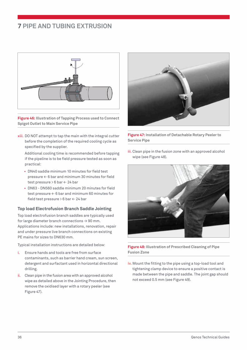
7 PIPE AND TUBING EXTRUSION
36 Qenos Technical Guides
Figure 46: Illustration of Tapping Process used to Connect Spigot Outlet to Main Service Pipe
xiii. DO NOT attempt to tap the main with the integral cutter before the completion of the required cooling cycle as specified by the supplier.
Additional cooling time is recommended before tapping if the pipeline is to be field pressure tested as soon as practical:
• DN40 saddle minimum 10 minutes for field test pressure ≤ 6 bar and minimum 30 minutes for field test pressure > 6 bar ≤ 24 bar
• DN63 - DN560 saddle minimum 20 minutes for field test pressure ≤ 6 bar and minimum 60 minutes for field test pressure > 6 bar ≤ 24 bar
Top load Electrofusion Branch Saddle JointingTop load electrofusion branch saddles are typically used for large diameter branch connections ≥ 90 mm. Applications include: new installations, renovation, repair and under pressure live branch connections on existing PE mains for sizes to DN630 mm.
Typical installation instructions are detailed below:
i. Ensure hands and tools are free from surface contaminants, such as barrier hand cream, sun screen, detergent and surfactant used in horizontal directional drilling.
ii. Clean pipe in the fusion area with an approved alcohol wipe as detailed above in the Jointing Procedure, then remove the oxidised layer with a rotary peeler (see Figure 47).
Figure 47: Installation of Detachable Rotary Peeler to Service Pipe
iii. Clean pipe in the fusion zone with an approved alcohol wipe (see Figure 48).
Figure 48: Illustration of Prescribed Cleaning of Pipe Fusion Zone
iv. Mount the fitting to the pipe using a top-load tool and tightening clamp device to ensure a positive contact is made between the pipe and saddle. The joint gap should not exceed 0.5 mm (see Figure 49).

PIPE AND TUBING EXTRUSION 7
37Qenos Technical Guides
Figure 49: Illustration of Top-load Tool Attached to Both the Saddle and Pipe
v. Connect the terminals and apply the fusion voltage following the method outlined above in Jointing Procedure.
vi. The completed joint should be left in the clamps for cooling. The time needed will be specified on the fitting label, or by its data carrier, or in the display of the automatic control box.
Maintenance, servicing and calibrationAll equipment should be well maintained and kept in a clean condition at all times.
The equipment should be serviced and calibrated regularly. The frequency at which this is carried out will be different for individual items of equipment and will also depend on usage, but should be at least once every 12 months. Guidance should be sought from the equipment manufacturer and a scheme of calibration and servicing should be implemented. Particular attention should be given to the control box, the generator and the scraping (or peeling) tools. The sharpness of the cutter head of tools should be checked at least on a monthly base.
Records1. Job SupervisionElectronic or written records of appropriate fusion procedure for each joint should be kept as required.
2. Equipment Servicing and CalibrationElectronic or written records of appropriate servicing and calibration should be kept. The minimum information to be recorded is given in Appendix 1.
3. TrainingInstructions should be provided by Registered Training Organisations (RTO’s) that are accredited by State/Territory Training Authorities under the Australian National Training Authority (ANTA) guidelines and complying with PMB 01 - Competency Standards prepared by Manufacturing Learning Australia, Qualification Framework for the plastics, rubber and cable making industry.
The RTO’s providing training in all forms of welding plastics pipeline systems must have staff qualified in presenting courses that meet competency standards covered by sections PMBWELD301A through to PMBWELD311A in PMB 01.
The RTO’s normally issue an accreditation certificate to successful candidates completing the training course and maintain a register of accredited welders.
Quality AssuranceTo achieve consistently good quality fusion joints as outlined by these guidelines, manufacturers and installers should operate a quality system in accordance with the principles of AS/NZS ISO 9001.
Assessment of the achievement would take the form of an audit against the points below. Independent testing of fusion joints may also be required.

7 PIPE AND TUBING EXTRUSION
38 Qenos Technical Guides
Management Responsibility1. Customer Focus The organisation responsible for the jointing operation should ensure that customer requirements are determined and are met with the aim of enhancing customer satisfaction.
2. Planning The organisation responsible for the jointing operation should ensure that all aspects of the jointing operation are given adequate consideration prior to the commencement of work.
3. Responsibility, Authority and Communication On each site where pipes and fittings are to be jointed in accordance with these guidelines, a person should be nominated to supervise work affecting the jointing quality. The person should:
• Have the responsibility and authority to ensure effective jointing operations
• Ensure that processes needed for jointing operations are established, implemented and maintained
• Be able to communicate the requirements for effective jointing operations
Control of DocumentsDocument control should ensure that:
• Documents are approved for adequacy prior to use,
• The relevant versions of applicable documents are available at points of use,
• Documents remain legible and readily identifiable,
• The unintended use of obsolete documents is prevented, and to apply suitable identification to them if they are retained for any purpose.
1. PurchasingThe installer should ensure that purchased items including pipe, fittings and fusion jointing equipment conform to specified requirements.
2. Fusion Jointing ControlThe installer should ensure that fusion jointing procedures as well as servicing and maintenance of fusion jointing equipment are carried out in accordance with the specified guidelines.
3. Inspection and Testinga. Inspection of goods received and used on site The installer should ensure that incoming pipe, fittings
and fusion jointing equipment are not used until they have been inspected and confirmed as conforming to specified requirements including appearance and marking. Any non-conforming items should be identified, recorded and segregated.
b. Final inspection and testing At the commencement of each contract, the frequency
and type of inspection by the installer should be agreed with the client and documented.
c. Inspection and test records The installer should establish and maintain electronic
and/or written records of appropriate fusion jointing procedures, servicing and calibration details in accordance with these guidelines.
4. Corrective ActionThe installer should establish and maintain procedures to show evidence of:
• Review of non-conformities (including customer complaints) as a result of poor quality joints
• Determining the causes of poor quality joints
• Evaluating the need for action to ensure poor quality joints do not recur
• Determining and implementing action needed
• Recording the results of action taken, and
• Reviewing corrective action taken
5. Preservation of ProductThe installer should establish and maintain appropriate procedures for handling and storage of pipe, fittings and fusion jointing equipment on site.
NOTE: Damaged packaging can permit ingress of dirt and moisture, which can adversely affect joint integrity.
6. Control of RecordsThe installer should establish and maintain procedures for collection, indexing, filing and storage of quality records for a minimum period of 6 years from the date of installation.
PIPE AND TUBING EXTRUSION 7
39Qenos Technical Guides
7. Competence, Awareness and TrainingThe installer should:
• Determine the necessary competence for personnel performing fusion jointing
• Provide training or take other actions to satisfy these guidelines
• Evaluate the effectiveness of the actions taken
• Ensure that personnel are aware of the relevance and importance of their activities and how they contribute to the achievement of effective fusion jointing, and
• Maintain appropriate records of education, training, skills and experience

7 PIPE AND TUBING EXTRUSION
40 Qenos Technical Guides
APPENDIX 1 – RECORD SHEETSRecord sheets should be maintained for all equipment required for all fusion jointing operations. The sheet should be headed:
‘SERVICING AND CALIBRATION RECORD SHEET’
Followed by:
‘ELECTROFUSION SOCKET EQUIPMENT OR ELECTROFUSION SADDLE EQUIPMENT’
Then the appropriate sub-title from the following list (additional record sheets may be kept if required):
• Electrofusion socket jointing:
• Generators
• Electrofusion control box
• Electrical safety test
• Electrofusion saddle jointing:
• Generators
• Electrofusion control box
• Electrical safety test
The information recorded on the sheet should include, but not be restricted to:
• The date of servicing or maintenance
• The name, address and telephone number of the undertaking or contractor operating the equipment
• The name, address and telephone number of the company conducting the service or maintenance
• The member (or members) of staff responsible for servicing or maintenance
• The serial number of the equipment
• The details of service and/or maintenance carried out. This should include relevant details of test equipment, procedures and/or manuals used, and relevant ambient conditions.
• The signature(s) of the member (or members) of staff responsible for the servicing or maintenance operations conducted

PIPE AND TUBING EXTRUSION 7
41Qenos Technical Guides
APPENDIX 2 – PIPE EXTRUSION TROUBLESHOOTING GUIDE
Problem/ Issue Cause(s) Potential Solution(s)/ Action(s)
Die (extrudate) lines.
Damage to the exit edges of the tip or die. Refinish tip or die exit edges to sharp and uniform about the diameters.
Die drool or build-up on the tip or die faces. Adjust temperature of the die exit accordingly
Extruder surging Too fast extruder throughput relative to OEM Extruder specifications
Check OEM guaranteed extruder throughput and run extruder within specifications
Improper extruder temperature settings Adjust temperature setting according to OEM recommendations
Poor resin- extruder design match versus extruder OEM specifications for throughput
Discuss with resin supplier and implement actions to ensure extruder runs within OEM specifications
Extruder not set as per OEM design specifications Check with OEM and ensure compliance with design specifications
Gels and other contaminations in pipe
Resin contains foreign particles/ contaminated with gels etc
Check with resin supplier for presence of gels etc.
Check regrind for contaminants
Degraded resin coming off the die during extrusion Follow proper shut-down procedures for extruder to avoid long exposure of resin to excessive temperatures
Localised thick spots in pipe wall
Improper die setting Adjust the die setting
Hot and cold spots in die profile temp Check for uniformity in die heating
Uneven pipe drag downstream of the extruder Check for spots in cooling baths which could cause pipe drag
Haul-off slippage Check and adjust haul-off
Uneven melt delivery from die -extruder surging Check remedies for extruder surging
Vacuum calibrator and die not levelled well Adjust the position of the vacuum bath relative to the die
Pipe out of round Sizing device (calibrator) in adequate or out of shape
Check the calibrator for concentricity.
Ensure it is 3–5% larger than the final pipe diameter
Pipe is too warm when it reaches the haul off unit Ensure sufficient downstream cooling length before pipe gets to the haul off unit
Decrease throughput
Wrong vacuum setting in vacuum tanks Ensure proper vacuum setting in vacuum tanks
Pipe tear Haul-off too fast Check and adjust the speed of haul off
Pipe too hot at the entrance to calibrator Check for water flows on calibrator and adjust to avoid hot spots
Ensure adequate calibrator size
Pipe dragging in cooling tanks Check and eliminate drag spots
Pipe sag Melt temperature too high Adjust extruder temperature setting and throughput to lower melt temperature
Die gap not adjusted to accommodate sag Adjust die gap – wider at the top and narrower at the bottom of the die
Resin’s inherent resistance to sag is not adequate for the pipe wall thickness
Use low-sag resin
No enough cooling capability in line Ensure adequate water temperature in cooling baths and enough cooling length

7 PIPE AND TUBING EXTRUSION
42 Qenos Technical Guides
Problem/ Issue Cause(s) Potential Solution(s)/ Action(s)
Rough surface inside or outside
Moisture in resin Ensure minimum of 1.5 hrs drying of resin at 70–90°C
Not adequate water flows setting to the calibrator Adjust water flows to calibrator
Melt temperature too low Increase die/ and or extruder temperatures
Thermal degradation of pipe-failed OIT
Too high melt temperature Adjust extruder/ and or die temperatures accordingly
Excessive extruder screw speed Lower extruder throughput
Die too small for required throughput Ensure adequate die size
Die pin too hot Check operation of pin cooling otherwise decrease throughput
Extruder surging Check remedies for extruder surging
Uneven pipe cut The saw blade is flexing Get thicker/ larger blades
The saw blade is lose Check and fix
Saw arm is entering pipe too quickly and with insufficient revolutions
Adjust as required
The saw arm is lose or bushes worn and is ‘floating’ Check and fix
There is wear/slack in slip rings of the saw planetary components
Check and fix
Uneven speed of haul-off or cutting carriage Check uniformity of the speed of haul-off and cutting carriage
Saw is not capable of cutting the pipe Check with OEM for saw specifications
Uneven wall thickness
Uneven melt delivery from the die -extruder surging Check remedies for extruder surging
Uneven take-off speed Check haul-off unit
Improper alignment of die and haul-off units Check for alignment
Die and pin not centred evenly Even die gap
Excessive sag of a polymer Check remedies for pipe sag
Voids in pipe Moisture in resin Ensure minimum of 1.5 hrs drying of resin at 70–90°C
Trapped air Adjust extruder temperature setting and back pressure accordingly
Disclaimer
The proposed solutions in this guide are based on conditions that are typically encountered in the manufacture of products from polyethylene. Other variables or constraints may impact the ability of the user to apply these solutions. Qenos also refers the user to the disclaimer at the beginning of this document.

PIPE AND TUBING EXTRUSION 7
43Qenos Technical Guides
BIBLIOGRAPHY/FURTHER READING1. Janson, L. E.; Plastic Pipes for Water Supply and Sewage Disposal (4th Ed.), Borealis, 2003.
2. Brömstrup, H.; PE100 Pipe Systems (2nd Ed.), Vulkan-Verlag GmBH, 2004.
3. Hensen, F.; Plastic extrusion Technology, Hanser Verlag, 1997.
4. Michaeli, W.; Extrusion Dies, Hanser Verlag, 2003.
5. Technical Manual – Materials for Pipe Extrusion, Hostalen, Lupolen, -Processing and Applications, Basell Polyolefins.
6. Reliable Pipelines with Hostalen CRP 100, Properties, Practical Experience and Standards, Hoechst.
7. Battenfeld Extrusionstechnik – SMS Group, Pipe Extrusion Plant.
8. AS/NZS 4131:2010, Polyethylene (PE) compounds for pressure pipes and fittings.
9. AS/NZS 4130:2009, Polyethylene (PE) pipes for pressure applications.
10. ISO 9080:2003, Plastic piping and ducting systems – Determination of the long-term hydrostatic strength of thermoplastics materials in form by extrapolation.
11. ISO 13479:2009, Polyolefin pipes for the conveyance of fluids – Determination of resistance to crack propagation – Test method for slow crack growth on notched pipes (notch test).
12. ISO 13477:2008, Thermoplastic pipes for the conveyance of fluids – Determination of resistance to rapid crack propagation (RCP) – Small-scale steady-state test (S4 test).
13. ISO 4437:2007, Buried polyethylene (PE) pipes for the supply of gaseous fuels – Metric series – Specifications.
14. ISO 4427 – 1:2007, Plastics piping systems – Polyethylene (PE) pipes and fittings for water supply. PMBWELD301B Butt Weld PE Pipelines Resource Manual, Chisholm Institute, 2010
15. Industry Guidelines, Butt Fusion Jointing of PE Pipes and Fittings, PIPA, 2011.
16. Industry Guidelines, Butt Fusion Jointing of PE Pipes and Fittings for Pressure Applications, PIPA, 2011.
17. Industry Guidelines, Temperature Rerating of PE Pipes, PIPA, 2010.
Issued July 2015.


Polyethylene Technical Guide Series
POLYETHYLENE BLOW MOULDING –TECHNICAL GUIDE
08PIPE AND TUBING EXTRUSION –TECHNICAL GUIDE
07ROTATIONAL MOULDING–TECHNICAL GUIDE
06INJECTION MOULDING–TECHNICAL GUIDE
05
EXTRUSION COATING & LAMINATION–TECHNICAL GUIDE
04FILM EXTRUSION AND CONVERSION–TECHNICAL GUIDE
03EXTRUSION–TECHNICAL GUIDE02GENERAL
PROPERTIES–TECHNICAL GUIDE
01

Qenos Pty Ltd471 Kororoit Creek RdAltona Victoria 3018 AustraliaPhone 1800 063 573 Fax 1800 638 981ABN 62 054 196 771–qenos.com