extrusion of 7075 aluminium alloy through double-pocket dies to manufacture a complex profile...
Post on 22-Dec-2015
217 views
TRANSCRIPT

EXTRUSION OF 7075 ALUMINIUM ALLOY
THROUGH DOUBLE-POCKETDIES TO MANUFACTURE A
COMPLEX PROFILE
Presenter: Christina Lambertson
Date: September 13, 2010
Authors: Gang Fang, Jie Zhou, Jurek Duszczyk

Introduction
AA7075 is a high strength aluminum alloy used in aircraft and aerospace.
The alloy is difficult to extrude especially with complex cross-section shapes.
This alloy has higher flow stresses that are sensitive to strain rate and temperature.
Die design and process optimization for the alloy were considered in the manufacture of a complex solid profile with differences in wall thicknesses.
Knowing the effects of extrusion on the alloy will help us to know how fast to extrude it and what kind of die to use so as not to get defects in the product.

References
1. Arentoft, M., Gronostajski, Z., Niechajowicz, A., Wanheim, T., 2000. Physical and mathematical modelling of extrusion processes. J. Mater. Process. Technol. 106, 2–7.
2. Dixon, B., Extrusion of 2xxx and 7xxx alloys 2000. Proceedings of the 7th International Aluminium Extrusion Technology Seminar, vol. 1. Aluminium Association and Aluminium Extruder’s Council, Wauconda, Illinois, pp. 281–294.
3. Flitta, I., Sheppard, T., 2003. Nature of friction in extrusion process and its effect on material flow. Mater. Sci. Technol. 19, 837–846.
4. Gouveia, B.P.P.A., Rodrigues, J.M.C., Martins, P.A.F., Bay, N., 2001. Physical modelling and numerical simulation of the round-to-square forward extrusion. J. Mater. Process. Technol. 112, 244–251.
5. Johnson, W., Kudo, H., 1962. The Mechanics of Metal Extrusion. Manchester University Press, Manchester, p. 60.
6. Kayser, T., Parvizian, F., Hortig, C., Svendsen, B., 2008. Advances on extrusion technology and simulation of light alloys. Key Eng. Mater. 367, 117–123.
7. Lee, W.-S., Sue, W.-C., Lin, C.-F., Wu, C.-J., 2000. The strain rate and temperature dependences of the dynamic impact properties of 7075 aluminium alloy. J. Mater. Process. Technol. 100, 116–122.
8. Lee, G.-A., Kwak, D.-Y., Kim, S.-Y., Im, Y.-T., 2002. Analysis and design of flat-die hot extrusion process 1. Three-dimensional finite element analysis. Int. J. Mech. Sci. 44, 915–934.
9. Li, Q., Smith, C.J., Harris, C., Jolly, M.R., 2003a. Finite element investigations upon the influence of pocket die designs on metal flow in aluminium extrusion, part I, effect of pocket angle and volume on metal flow. J. Mater. Process. Technol. 135, 189–196.
10.Li, L., Zhou, J., Duszczyk, J., 2003b. Prediction of temperature evolution during the extrusion of 7075 aluminium alloy at various ram speeds. J. Mater. Process. Technol. 145, 360–370.
11.Prassad, Y.V.R.K., Sasidhara, S., 1997. Hot Working Guide: A Compendium of Processing Maps. ASM International, Materials Park, Ohio, pp. 139–141.
12.Sheppard, T., Tunnicliffe, P.J., Patterson, S.J., 1982. Direct and indirect extrusion of a high strength aerospace alloy (AA7075). J. Mech. Work. Technol. 6, 313–331.
13.Shikorra, M., Donati, L., Tomesani, L., Tekkaya, A.E., 2007. Extrusion Benchmark 2007—benchmark experiments: study on material flow extrusion of a flat die. Key Eng. Mater. 367, 1–8.
14.Zakharov, V.V., 2005. Scientific aspects of deformability of aluminium alloys during extrusion. Adv. Perform. Mater. 2, 51–66.
15.Zhou, J., Li, L., Duszczyk, J., 2003. 3D FEM simulation of the whole cycle of aluminium extrusion throughout the transient state and the steady state using the updated Lagrangian approach. J. Mater. Process. Technol. 134, 383–397.

Models and Design Principles
Fig. 1 – Cross-section shape and dimensions of the extrudate and the basic design of the double-pocket die (half model) (b1—die bearing 1 behind Pocket 1 and b2—die bearing 2 behind Pocket 2).
Table 1 – Die bearing lengths behind Pocket 1 and Pocket 2
Bearing, b1 [mm] Bearing, b2 [mm]
Die No. 1 2.5 3.5
Die No. 2 5.0 6.0
Die No. 3 10.0 11.0

Models and Design Principles
Table 2 – Physical properties of the workpiece and extrusion tooling and heat transfer coefficients
Physical properties AA7075
H13 tool steel
Heat capacity [N/(mm2 ◦C)] 2.39 5.6
Thermal conductivity [W/(m ◦C)] 130 28.4
Heat transfer coefficient between tooling and workpiece [N/(◦Csmm2)]
11 11
Heat transfer coefficient between tooling/workpiece and air [N/(◦Csmm2)]
0.02 0.02
Emissivity 0.1 0.7
Table 3 – Process parameters and billet dimensions used in FEM simulation and experiments
Initial temperature (◦C)
Die 450
Stem 450
Container 450
Billet 470
Ram speed [mm/s] 0.4, 0.6
Extrusion speed [m/min]
0.51, 0.76
Billet diameter [mm] 110
Billet length [mm] 220
Extrusion ratio 21.23
fs=mk: where fs is the frictional stress, k the shear yield stress of the deforming workpiece, and m the friction factor. This equation is used to represent the friction between the workpiece and die and between the workpiece and container.

Results
There were many different kinds of software or equipment used when performing this experiment. DEFORM 3D FEM-based commercial
software package AMD quad processer
station Three different sized dies
Fig. 3 – Example of a double-pocket die used in extrusion experiments.

Results
Both simulations and experiments were performed.
Using the FEM software simulations were able to be performed with different temperatures as expressed in table 3.
Real experiments were then performed using the same temperatures as the FEM simulations.
Fig. 2 – FEM meshes of the billet, die and other extrusion tooling.

Results
Fig. 5 – (a) Experimental and (b) simulated extrudate front ends through Die No. 2 with a difference of 0.6% in the radius of the curvature.
From these two pictures we can see that there is a difference in what the simulation will give and what we get from real experiments.
The example from the experiment shows that it has a larger radius of curvature after it is extruded.

Results
We can see that between the three dies that temperature distributions are different.
Fig. 9 – Temperature distributions of the workpiece during extrusion through Die No. 2 with bearing lengths of 5 and 6mm and at a ram speed of 0.6mm/s (s—ram displacement): (a) s = 9.45mm, (b) s = 11.10mm and (c) s = 12.10mm.

Results
From this graph we can see how the temperature is effected by the ram stroke.
The bigger the ram stroke the higher the temperature gets.
The rate at which it is extruded does not really effect temperature as can be seen here.
Fig. 10 – Evolutions of the maximum temperatures of the workpiece through the three dies and at extrusion speeds of 0.51 and 0.76m/min (simulation results).
Results
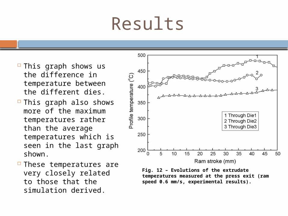
This graph shows us the difference in temperature between the different dies.
This graph also shows more of the maximum temperatures rather than the average temperatures which is seen in the last graph shown.
These temperatures are very closely related to those that the simulation derived.
Fig. 12 – Evolutions of the extrudate temperatures measured at the press exit (ram speed 0.6 mm/s, experimental results).

Results
The difference in these pictures is that there are defects in two of the specimens.
These cracks appeared because the temperature exceeded the critical value and was too high.
Fig. 13 – Extrudate surface quality determined mainly by the temperatures at the extrudate tips: (a) perfect surface, (b) surface with mini-cracks and (c) surface with hot shortness.

Conclusions
Ram speed and temperature affect the surface quality of AA7075 high strength aluminum in the extrusion process.
From the simulations and experiments it was shown that the simulation data was very close to experiment data.
These tools can now be used and applied to other shapes in the extrusion process or to other alloys.