eye tracking and roi detection within a computer screen
TRANSCRIPT

Eye Tracking and ROI Detectionwithin a Computer ScreenUsing a Monocular Camera
Guangmin Sun, Junjie Zhang, Kun Zheng∗ and Xiaohui Fu
Faculty of Information Technology, Beijing University of Technology, 100Pingleyuan, Beijing 100124, ChinaE-mail: [email protected]∗Corresponding Author
Received 09 September 2020; Accepted 25 September 2020;Publication 22 December 2020
Abstract
The region of interest will change according to the task, even in the samesituation. In the study, a method for region of interest detection within acomputer screen using a monocular camera is proposed. In contrast to gazetracking techniques that require particular devices (e.g., an eye tracker andRGB-D device) meanwhile complex calibration, a cheap and more conve-nient monocular camera is used in this study to solves the eye gaze trackingproblem. Firstly, Human face is detected in a real-time video sequenceusing HoG features. Then, the landmarks around the eyes, which reflectthe gaze position, are extracted. Next, the iris centers are detected in theeye region. In order to reduce the gaze error caused by head movement, athree-dimensional head model is proposed to estimate head pose. Finally,the eye region is tracked by calculating the eye vectors and head movement.Experiments were performed to evaluate the face detection, landmarks, irisdetection, eye movement estimation, and head pose estimation on databasessuch as the Hong Kong, BioID, and Boston University head pose databases.Besides, experiments for gaze tracking were performed for a real-time video
Journal of Web Engineering, Vol. 19 7–8, 1117–1146.doi: 10.13052/jwe1540-9589.19789© 2020 River Publishers

1118 G. Sun et al.
sequence. Deviation is calculated using Euclidean distance between the realand estimated points. The results show that the method achieves an averageerror of 1.85◦ with head fixed and 3.58◦ with head movement in the rangeof −45◦ and 45◦. The requirement is detecting the user’s attention in thescreen area. Our method can reach the same level to the other methods, eventhough the accuracy is not state-of-the-art. Meanwhile, as we all know notonly a specific point is concerned but also a region area according to thecharacteristics of human eye imaging, thus the proposed method can meetthe requirements of demand.
Keywords: Iris detection, gaze tracking, monocular camera, ROI detection.
1 Introduction
As computer science and technology continue to develop, the field ofhuman-computer interaction has attracted the attention of an increasingnumber of researchers because of the ever-changing requirement of human-computer interaction applications. Human-computer interaction technologyhas evolved from monotonous keyboard and character display interactions totoday’s complex and diverse multimedia interactions. Therefore, combinedwith manual input, human-computer interaction using various media such asgaze tracking and speech recognition has become increasingly popular.
Over 80% of information can be obtained through the visual system.The eye plays an important role in expressing a person’s emotional state,needs, cognitive processes, and other factors. In addition, habits or intentioncan be determined by what a user is looking at. Therefore, gaze tracking isan important part in the field of human-computer interaction. Using a gazetracking device to collect the changes in a user’s visual line-of-sight, his orher mental intentions and behaviors can be perceived. These data can reflectthe relationship between a user’s eye movement information and his or herchoices in thinking and cognition and provide a theoretical and practicalbasis for psychological and ophthalmology research. Nowadays, some com-panies and research institutes have developed a series of high-precision gazetracking systems based on professional equipment. These systems are usedin environments such as medical laboratories, assisted driving systems, andclassrooms. However, commercial gaze tracking systems are very expensive,which limits their use. Meanwhile, most of the gaze tracking devices onthe market rely on active infrared light sources or stereo camera devices,which require specialized hardware support as well as complex hardware

Eye Tracking and ROI Detection within a Computer Screen 1119
parameter and position calibration. They are hence unsuitable for analyzinguser behavior in the education and advertising fields. To carry enable gazetracking to be used more widely, a system that tracks gaze without specialistor invasive equipment can be designed if a single monocular camera is used.
In the study, we propose a method to eye gaze tracking and region ofinterest (ROI) detection using a monocular camera such as those installedon personal computer. First, human face is detected in the real-time videosequence. Then, regression trees are used to extract eye landmarks. Third,Hough algorithm is used to detect irises in the eye region. In order to decreasegaze error caused by head movement, a three-dimensional 3D head model isadopted to estimate head pose. Finally, the eye vectors and head movementinformation are used to track eye gaze and detect the ROI.
The structure of this paper is as follows: Section 2 reviews related studiesabout gaze detection. The methods of gaze tracking are presented in Sec-tion 3, including face detection, extract eye features, eye region detection, irisdetection, and head pose estimation. In Section 4, we evaluate the proposedmethod, and Section 5 presents the conclusions.
2 Related Studies
The eye feature is an important part of gaze tracing and can reduce thecomplexity of feature extraction. Wen and Li [1] performed feature extractionusing a CNNs (convolutional neural network) to remove blinking imagesand predict coarse gaze position. However, it is not convenient to collect alarge amount of raw data to train model. Zhang [2] presents a method byusing the Canny operator to extract the iris edges, selecting the two longestvertical edges for ellipse fitting to locate the iris centers. However, featureextraction under natural light is affected by illumination changes and therobustness of this system cannot be guaranteed. Valenti et al. [3] computedhead pose to reduce eye tracking error. Kasinsi [4] detected face regionsusing a Haar cascade, but this method is not an effective way to detect facesunder varying illumination and side poses. Yiu and Qin [5] combined headpose and eye tracking, but the head movement must remain within a smallrange. Some researchers use RGB-D cameras to track sight. For example,Sun and Yin propose a head pose estimation method based on 3D facialmodels [6]. Symmetry plane was used to estimate the pose orientation. Acentral profile-based 3D face pose estimation algorithm was developed byPedrycz and Li [7]. In order to conduct the Hough transform in a parameterspace, an objective function was defined and they maps the face profile to an

1120 G. Sun et al.
accumulator cell. They calculate the accumulator cell and set the maximumaccumulator cell as the central profile. Roll and yaw were determined afterthe symmetry plane had been computed, because the objective function wasbased on three parameters. The algorithm can detect the nose tip using thedetected central profile. Once the nose tip, nose ridge and nose bottom pointswere determined, pitch angle was estimated. Kong [8] presented a system thathead pose can be estimated by using depth information from a simple RGB-D camera. However, an RGB-D camera is more expensive than a monocularcamera.
3 Proposed Method
The center of iris and six key points around each eye plays an importantpart in a face region (see Figure 1). The eyeball moves in the eye socket asuser looking at different content on the computer screen. The six key pointsaround each eye can be treated as reference points, and the direction of eyegaze can be reflected by the position changes of iris center in the eyeball.Thus, the gaze vector formed by the iris center and six key points aroundeach eye contains the information of gaze direction, which can be used forgaze tracking. However, it is difficult to detect the gaze vector when the headmoves, we cannot get a high accuracy in the estimated gaze location. Thus,the head location should be considered to countervail for the head movement.
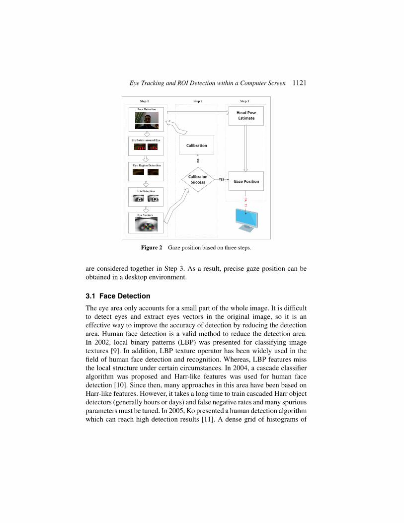
There are three phases in the gaze track system, meanwhile eye featuresand head pose information are considered together to improve the accuracyof the gaze point estimation (see Figure 2).
In Step 1, the face region is extracted from captured webcam video. Then,the eyes in the face region were detected and we extract the eye features andiris centers in the eye region to determine the eye movement information.In Step 2, mapping vectors for the gaze position are obtained. The vectorsand iris position that reflect the gaze position from Steps 1 and 2 will beaffected by random head movements. To eliminate the influence of headposes and decreases the gaze position error, head pose and eye movements
(a) (b)
Figure 1 Six key points around the (a) left and (b) right eyes: 300-W database was used totrain the model [15–17].
Eye Tracking and ROI Detection within a Computer Screen 1121
Step 1 Step 2 Step 3
Face Detection
Eye Region Detection
Six Points around Eye
Iris Detection
Eye Vectors
Calibration
Calibraion Success
No
Gaze Position
Head Pose Estimate
XY
Figure 2 Gaze position based on three steps.
are considered together in Step 3. As a result, precise gaze position can beobtained in a desktop environment.
3.1 Face Detection
The eye area only accounts for a small part of the whole image. It is difficultto detect eyes and extract eyes vectors in the original image, so it is aneffective way to improve the accuracy of detection by reducing the detectionarea. Human face detection is a valid method to reduce the detection area.In 2002, local binary patterns (LBP) was presented for classifying imagetextures [9]. In addition, LBP texture operator has been widely used in thefield of human face detection and recognition. Whereas, LBP features missthe local structure under certain circumstances. In 2004, a cascade classifieralgorithm was proposed and Harr-like features was used for human facedetection [10]. Since then, many approaches in this area have been based onHarr-like features. However, it takes a long time to train cascaded Harr objectdetectors (generally hours or days) and false negative rates and many spuriousparameters must be tuned. In 2005, Ko presented a human detection algorithmwhich can reach high detection results [11]. A dense grid of histograms of

1122 G. Sun et al.
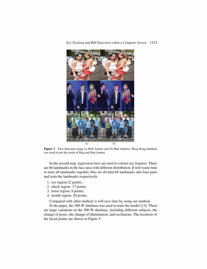
oriented gradients (HoG) was used in the method, computed over blocks of16 × 16 pixels used as a detection window. This representation has proven tobe powerful enough to classify humans using a linear support vector machine.The result of human face detection will be influenced by large variation, suchas different illuminations, facial expressions, and backgrounds, thus humanface detection remains a challenging issue in real world applications. ForShuo-Yang’s Hong Kong database, which contains extremely complicatedbackgrounds and dramatic illumination changes, the HoG feature achievesa much higher detection accuracy than the Harr-wavelet feature. Moreover,it is easy to train HoG features. We do not have to perform any tedioussubsampling or hard negative mining. As for the accuracy, it is easy to obtainthe same detection rate as Harr-wavelet features but with thousands of fewerfalse alarms. Examples of the use of HoG and Harr-wavelet features to detectfaces are shown in Figure 3.
Compared with HoG features, Harr wavelets are good at detecting texturefeatures (for instance, whether a target area is bright or dark), but they cannotdetect direction features effectively, which makes them less effective at targetrecognition. In short, HoG features are suitable for describing shapes andHarr features are suitable for describe shading. It is hence better to describea pedestrian or the shape of a target using HoG features, and in the proposedmethod, HoG features are used to detect faces.
3.2 Extracting the Features Around Each Eye
The eye region should be located to extract the eye features in the first place.Traditional eye region detection methods cannot get high accurate resultin facial with high illumination and moving heads. Therefore, an efficientapproach should be employed to overcome the influence of illumination andhead movement. Two steps are proposed to detect the eye region.
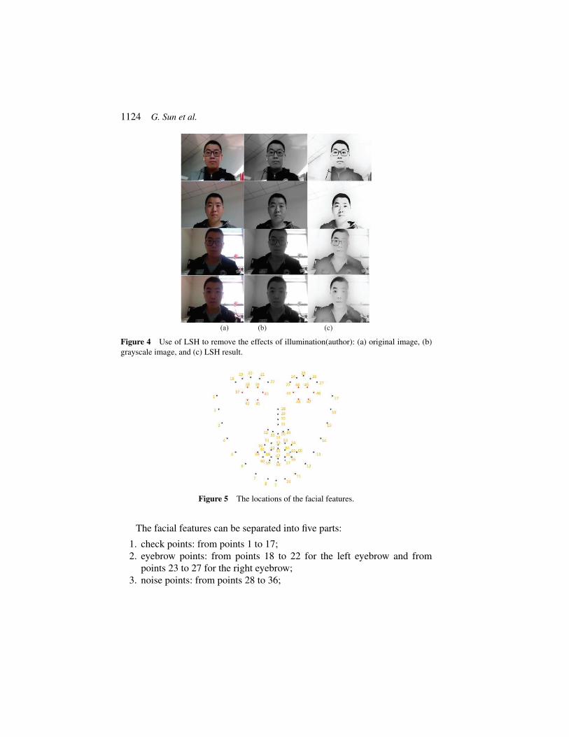
First of all, a locality sensitive histogram (LSH) [12] is employed to copewith lighting. Unlike other histogram-based methods to eliminate the effectsof lighting that count the frequency of occurrences of each intensity valueby incrementing the corresponding bin, an LSH is computed at each pixellocation and a floating-point value is added to the corresponding bin for eachoccurrence of an intensity value. Examples of using an LSH to eliminate theeffects of lighting are shown in Figure 4, where four images with differentsituations (facing toward the light and wearing glasses, facing toward the lightwithout glasses, facing away from the light and wearing glasses, and facingaway from the light without glasses) have been transformed into images withconsistent illumination.
Eye Tracking and ROI Detection within a Computer Screen 1123
(a) (b)
Figure 3 Face detection using (a) HoG feature and (b) Harr features: Hong Kong databasewas used to test the result of Hog and Harr feature.
In the second step, regression trees are used to extract eye features. Thereare 68 landmarks in the face area with different distribution. It will waste timeto train all landmarks together, thus we divided 68 landmarks into four partsand train the landmarks respectively:
1. eye region:22 points;2. check region: 17 points;3. noise region: 9 points;4. mouth region: 20 points.
Compared with other method, it will save time by using our method.In the paper, the 300-W database was used to train the model [13]. There
are large variations in the 300-W database, including different subjects, thechange of poses, the change of illumination, and occlusions. The locations ofthe facial points are shown in Figure 5.
1124 G. Sun et al.
(a) (b) (c)
Figure 4 Use of LSH to remove the effects of illumination(author): (a) original image, (b)grayscale image, and (c) LSH result.
Figure 5 The locations of the facial features.
The facial features can be separated into five parts:
1. check points: from points 1 to 17;2. eyebrow points: from points 18 to 22 for the left eyebrow and from
points 23 to 27 for the right eyebrow;3. noise points: from points 28 to 36;

Eye Tracking and ROI Detection within a Computer Screen 1125
(a) (b)
Figure 6 Eye-point detection results: (a) Georgia Tech face database[18] was used to testthe accuracy and (b) the accuracy was tested in real time.
4. eye points: from points 37 to 42 and 43 to 48 for the left eye and righteye respectively;
5. mouth points: from points 49 to 68.
Usually, an insensitive facial point to facial expression changes and eyestatus are selected as reference points for gaze detection, thus the inner, outer,upper eyelid, and lower eyelid points are selected. In the proposed method,eye points are used to reflect the state of the gaze. Examples of eye-pointdetection are shown in Figure 6. Because the gaze detection system used in adesktop environment, we assume that only one person sits in front of the table.Thus, the Georgia Tech face database [14] was used to test the accuracy ofeye feature detection.
3.3 Eye Region Detection
Each feature has the same label after the eye features have been extracted.The rule (Table 1) is used to extracted eyes region.

1126 G. Sun et al.
Table 1 The rule to extract eyes regionStart of left eyeregion
LeftEyePoint(point (37).x-18, min(point(38).y, point(39).y)-18)
width max(point(41).x,point(42).x)-min(point(38).x, point(39).x)+25
height point (40). y – point (37). y + 25
Start of righteye region
RightEyePoint(point (43).x-18, min(point(44).y,point(45).y)-18)
width max(point(47).x,point(48).x)-min(point(44).x, point(45).x)+25
height point (46). y – point (43). y + 25
(a) (b)
Figure 7 Eye region detection result: (a) images from the Georgia Tech face database [10]and (b) images during actual use.
The results of eye region detection can be seen from Figure 7. Thepictures in Figure 3.7(a) are from the same database and the pictures inFigure 7(b) were captured in an actual laboratory environment.
3.4 Iris Detection and Eye Vector
The center of iris and eye vectors are important features in the eye region, itis useful for us to estimate the gaze direction which can reflect the region ofinterest.
The iris center should be detected in the eye region after we extract theeye region. For most people, the iris shape is round, thus the circle Houghtransform (CHT) [15] algorithm is used to detect the iris in the eye region.

Eye Tracking and ROI Detection within a Computer Screen 1127
A
B
C
D
(a) (b)
x
y
a
b
Figure 8 A Circular Hough transformation from the x, y-space (a) to the parameter space (b).
The CHT is a specific modification of the Hough transform. The aim of thealgorithm is to find circles in noisy image input [15]. A circle can be describedin a two-dimensional space is that
(x− a)2 + (y − b)2 = r2 (1)
where (a, b) represent the center of the circle and r represent the radius. Theparametric representation of a circle is
x = a+ rcosθ, (2)
y = b+ rsinθ. (3)
Circle detection using the traditional CHT method has limitations: sincethe suitable parameters should be selected in three dimensional, a biggergrid size should be considered to solve the problem, it may require largeamounts of storage and computation. But it is very difficult to determine anappropriate grid size. To solve this problem, the Hough gradient is used todetect circles. First, any suitable edge detection technique (such as Sobel,Canny, or morphological operations) can be used to find all edges in theimage. We draw a circle around each edge point with the desired radius. Theilluminate can be seen from Figure 8.
It can be seen from Figure 8 that a value, b value and radii represent xaxis, y axis and z axis respectively. It is no longer voting in the parameterspace of a complete circle, the gradient vector is calculated at the contourpoint and then two points were set from the two sides of the contour pointdistance R in the gradient direction according to the radius of the search field.Finally, the center of the circle can be determined by the voting result. TheCHT method can detect more than one circle in the eye region, but just onecircle represents the iris. To select the one most likely to belong to the iris,
1128 G. Sun et al.
Figure 9 Results of iris detection: (top row) different eye images and (bottom row) detectionresults.
IEinnerEouter
Eul Eur
Ell Elr
Figure 10 Proposed Eye vector.
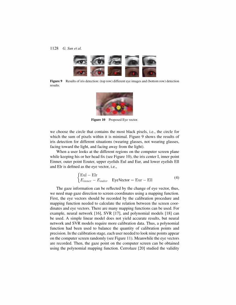
we choose the circle that contains the most black pixels, i.e., the circle forwhich the sum of pixels within it is minimal. Figure 9 shows the results ofiris detection for different situations (wearing glasses, not wearing glasses,facing toward the light, and facing away from the light).
When a user looks at the different regions on the computer screen planewhile keeping his or her head fix (see Figure 10), the iris center I, inner pointEinner, outer point Eouter, upper eyelids Eul and Eur, and lower eyelids Elland Elr is defined as the eye vector, i.e.,{
Eul− ElrEinner − Eouter EyeVector = Eur− Ell
(4)
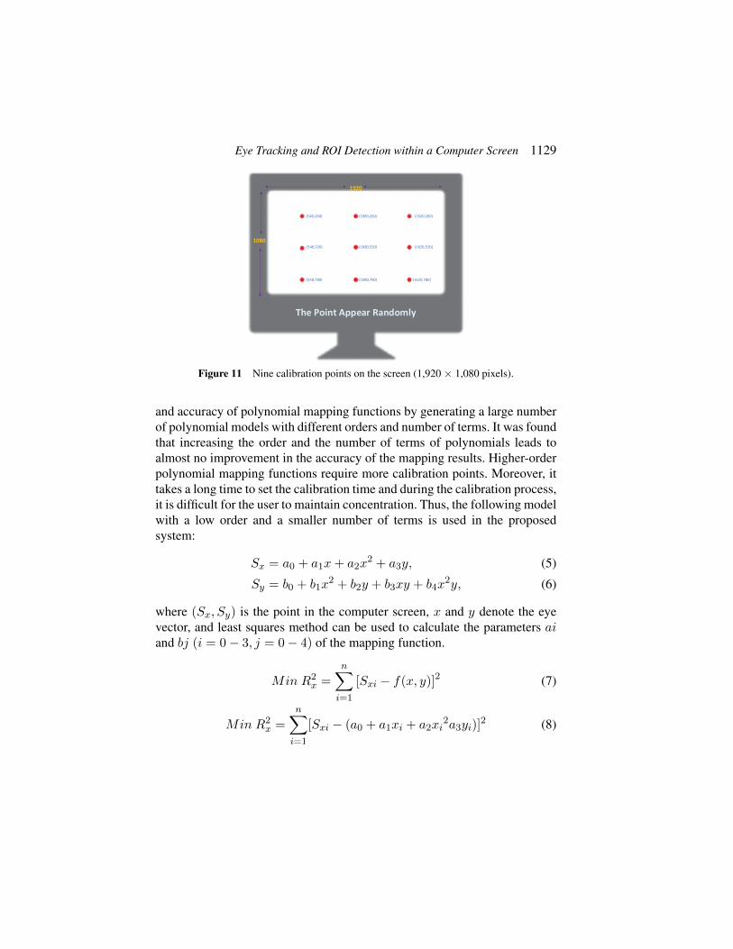
The gaze information can be reflected by the change of eye vector, thus,we need map gaze direction to screen coordinates using a mapping function.First, the eye vectors should be recorded by the calibration procedure andmapping function needed to calculate the relation between the screen coor-dinates and eye vectors. There are many mapping functions can be used. Forexample, neural network [16], SVR [17], and polynomial models [18] canbe used. A simple linear model does not yield accurate results, but neuralnetwork and SVR models require more calibration data. Thus, a polynomialfunction had been used to balance the quantity of calibration points andprecision. In the calibration stage, each user needed to look nine points appearon the computer screen randomly (see Figure 11). Meanwhile the eye vectorsare recorded. Then, the gaze point on the computer screen can be obtainedusing the polynomial mapping function. Cerrolaze [20] studied the validity
Eye Tracking and ROI Detection within a Computer Screen 1129
1920
1080
The Point Appear Randomly
(540,260)
(540,520)
(540,780)
(1080,260)
(1080,520)
(1080,780)
(1620,260)
(1620,520)
(1620,780)
Figure 11 Nine calibration points on the screen (1,920 × 1,080 pixels).
and accuracy of polynomial mapping functions by generating a large numberof polynomial models with different orders and number of terms. It was foundthat increasing the order and the number of terms of polynomials leads toalmost no improvement in the accuracy of the mapping results. Higher-orderpolynomial mapping functions require more calibration points. Moreover, ittakes a long time to set the calibration time and during the calibration process,it is difficult for the user to maintain concentration. Thus, the following modelwith a low order and a smaller number of terms is used in the proposedsystem:
Sx = a0 + a1x+ a2x2 + a3y, (5)
Sy = b0 + b1x2 + b2y + b3xy + b4x
2y, (6)
where (Sx, Sy) is the point in the computer screen, x and y denote the eyevector, and least squares method can be used to calculate the parameters aiand bj (i = 0− 3, j = 0− 4) of the mapping function.
Min R2x =
n∑i=1
[Sxi − f(x, y)]2 (7)
Min R2x =
n∑i=1
[Sxi − (a0 + a1xi + a2xi2a3yi)]
2 (8)

1130 G. Sun et al.
World Coordinates
Camera Coordinates
Image Plane
y
xHead
p
(x,y,z)
(x,y)
R,t
XY
Z
UV
W
Figure 12 Mapping a 3D point to a 2D point.
Figure 13 Three-dimensional head model based on the Biwi Kinect Head Posedatabase [20].
Min R2y =
n∑i=1
[Syi − f(x, y)]2 (9)
Min R2y =
n∑i=1
[Syi − (b0 + b1xi2 + b2yib3xiyi + b4x
2i yi)]
2 (10)
It is efficient to calculate the gaze point in each frame by using themapping function.
3.5 Head Pose Estimation
The gaze error is reduced if the head pose is estimated. In order to determinethe posture of the head, the 3D location of the head pose should be projectedonto a 2D location (see Figure 12).
To map a three-dimensional point to two-dimensional point, the locationin world coordinates should be known. When subjects use the system, theymay sit in front of the desk and face the computer; thus, a 3D head model canbe created, as shown in Figure 13[20].

Eye Tracking and ROI Detection within a Computer Screen 1131
The face orientation is determined by the six points of the nose tip, chin,left eye left corner, right eye right corner, left mouth corner, and right mouthcorner uniquely. The matrix of Rotation R and translation T can be calculatedusing these six points and the corresponding point locations detected in the2D image as follows: XY
Z
= R
ABC
+ T. (11)
After the rotation matrix and translation matrix have been calculated, thehead pose can be obtained.
4 Experiment
The face detection, eye points detection, iris detection, head pose estimation,and gaze detection were evaluated in this study.
The experimental hardware and development environments are listed inTables 2 and 3, respectively.
Table 2 Hardware environmentHardware DELL G3 3779
CPU Inter Core [email protected]
GPU Nvidia GeForce GTX 1060 with Max-Q Design (DELL)Intel(R) UHD Graphics 630
RAM 8GB (DDR4 2666MHz)
OS Windows 10 64bit (DirectX 12)
MONITOR CMN1738(17.2 inch) 1920*1080
CAMERA Integrated Webcam
Table 3 Development environmentWindows Version
MATLAB R2018b
Visual Studio 2015
OpenCV 2.4.13
EmguCV-CUDA 2.4.10.1940
CUDA v8.0

1132 G. Sun et al.
4.1 Face Detection
In order to obtain eye candidate area, it is necessary to detect the face in theoriginal picture. The accuracy of face detection directly affects the accuracyof eye detection. To evaluate the accuracy of face detection using HoGfeatures and Haar features, the database Faces in the Wild [21], which consistsof 30,281 faces collected from news photographs, ORL Face database [22],Yale Face database [23], and Georgia Tech Face database [24] were used. Inpractice, images were chosen such that the volunteers sat in front of a PC andonly one person appeared in the image. All databases except for Faces in theWild contain images with the same situation, in which each image containsonly one person. Different people may sit in front of a PC at differencedistances and whether they wear glasses or not may influence the accuracy offace detection. If people sit near the computer or away from the computer, themonocular camera cannot detect the face precisely; thus, the maximum andminimum distance sit in front of the PC was calculated. The images consist offour situations: wearing glasses and facing toward the light, wearing glassesand facing away from the light, not wearing glasses and facing toward thelight, and not wearing glasses and facing away from the light. Images weretaken in the daytime and in the evening. CEM LDM-100 was used to measurethe distances and the results are shown in Table 4.
The proposed method can work in different situations, especially in thedaytime when the user faces the light. In most of the strong light contrastsituations, such as when the user wears glass and faces away from the light,the proposed method can detect a face if it is a short distance away.
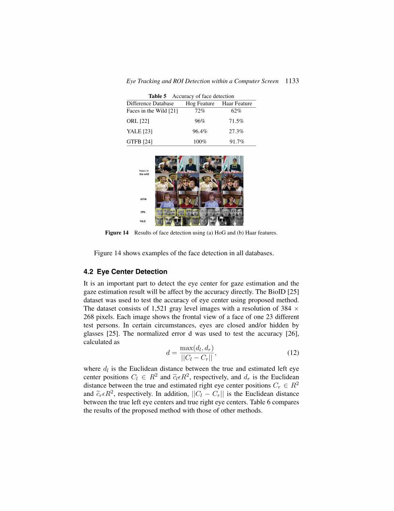
To select the best feature of face detection, all databases were used.Table 5 shows the results of face detection.
Table 4 Distances at which the user sat in front of the PCTime Glass Light Maximum Distance(m) Minimum Distance(m)Daytime Y Forward 1.751 0.485
Daytime N Backward 0.675 0.375
Daytime Y Backward 0.419 0.380
Daytime N Forward 1.716 0.453
Evening Y Forward 1.175 0.375
Evening N Backward 1.825 0.414
Evening Y Backward 1.680 0.410
Evening N Forward 1.175 0.389
Eye Tracking and ROI Detection within a Computer Screen 1133
Table 5 Accuracy of face detectionDifference Database Hog Feature Haar FeatureFaces in the Wild [21] 72% 62%
ORL [22] 96% 71.5%
YALE [23] 96.4% 27.3%
GTFB [24] 100% 91.7%
Figure 14 Results of face detection using (a) HoG and (b) Haar features.
Figure 14 shows examples of the face detection in all databases.
4.2 Eye Center Detection
It is an important part to detect the eye center for gaze estimation and thegaze estimation result will be affect by the accuracy directly. The BioID [25]dataset was used to test the accuracy of eye center using proposed method.The dataset consists of 1,521 gray level images with a resolution of 384 ×268 pixels. Each image shows the frontal view of a face of one 23 differenttest persons. In certain circumstances, eyes are closed and/or hidden byglasses [25]. The normalized error d was used to test the accuracy [26],calculated as
d =max(dl, dr)
||Cl − Cr||, (12)
where dl is the Euclidean distance between the true and estimated left eyecenter positions Cl ∈ R2 and c̃lεR2, respectively, and dr is the Euclideandistance between the true and estimated right eye center positions Cr ∈ R2
and c̃rεR2, respectively. In addition, ||Cl − Cr|| is the Euclidean distancebetween the true left eye centers and true right eye centers. Table 6 comparesthe results of the proposed method with those of other methods.
1134 G. Sun et al.
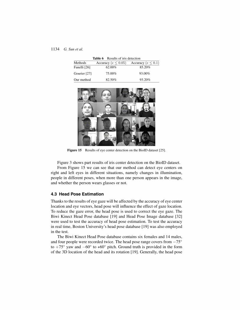
Table 6 Results of iris detectionMethods Accuracy (e ≤ 0.05) Accuracy (e ≤ 0.1)
Fanelli [26] 62.00% 85.20%
Gourier [27] 75.00% 93.00%
Our method 82.50% 93.20%
Figure 15 Results of eye center detection on the BioID dataset [25].
Figure 3 shows part results of iris center detection on the BioID dataset.From Figure 15 we can see that our method can detect eye centers on
right and left eyes in different situations, namely changes in illumination,people in different poses, when more than one person appears in the image,and whether the person wears glasses or not.
4.3 Head Pose Estimation
Thanks to the results of eye gaze will be affected by the accuracy of eye centerlocation and eye vectors, head pose will influence the effect of gaze location.To reduce the gaze error, the head pose is used to correct the eye gaze. TheBiwi Kinect Head Pose database [19] and Head Pose Image database [32]were used to test the accuracy of head pose estimation. To test the accuracyin real time, Boston University’s head pose database [19] was also employedin the test.
The Biwi Kinect Head Pose database contains six females and 14 males,and four people were recorded twice. The head pose range covers from−75◦
to +75◦ yaw and −60◦ to +60◦ pitch. Ground truth is provided in the formof the 3D location of the head and its rotation [19]. Generally, the head pose

Eye Tracking and ROI Detection within a Computer Screen 1135
Table 7 Results of head pose estimationRotation Angles Fanelli [26] Gourier [27] Fanelli [19] OursRoll 3.1 3.22 3.0 2.90
Yaw 5.4 5.33 6.10 5.23
Pitch 5.6 7.22 5.26 –
estimation error is measured using the following equation for the two (verticaland horizontal) angles or three rotation angles (pitch, roll, and yaw).
e =
√∑ni=1 (Xi −X)2
n− 1(13)
The Head Pose Image database is a benchmark of 2,790 monocular faceimages of 15 persons with variations of pan and tilt angles from −90◦ to+90◦. For every person, two series of 93 images are available [27, 28].
Table 7 shows the results of head pose estimation for all three head posedatabases.
To test the accuracy of head-pose estimation in real time, the BostonUniversity dataset was used. The database consists of 45 video sequences, inwhich five subjects were asked to perform nine different head motions underuniform illumination in a standard office setting [19]. In addition, the datasetconsists of two classes of sequence. One set of sequences was collectedunder uniform illumination conditions and the other set was collected undertime varying illumination. Each video sequence consists of 200 frames andshows people moving freely their head. Videos ssm5, vam6, and jim1, takenunder uniform illumination conditions, were used to test pitch, roll, yaw resultrespectively
The change of illumination will influence the result of head pose estima-tion. To test the robustness, videos jal4, jal8, and ssl6 were taken under timevarying illumination to test pitch, roll, yaw result respectively.
The result of the estimated head rotation angles compared with the groundtruth is shown in Figure 16.
High accuracy is obtained under both uniform and varying illumination.Figure 16(c) shows that it is difficult to measure pitch using only a monocularcamera, but the results are right. The pitch result under varying illuminationis explained in Figure 17, which shows that depth information cannot bemeasured using only a monocular camera.

1136 G. Sun et al.
(a) (b)
(c) (d) (e)
Figure 16 Results of head pose estimation in the Boston University head pose dataset [24]:(a) head movement under uniform illumination, (b) head movement under varying illumina-tion, (c) estimated pitch, (d) estimated roll, and (e) estimated yaw.
Figure 17 Explanation of the pitch results in Figure 16(c).

Eye Tracking and ROI Detection within a Computer Screen 1137
Screen
Camera
Figure 18 Eye sight detection system with a screen of dimensions 1,920 × 1,080 pixels.
4.4 Gaze Estimation
The gaze estimation system was implemented on a desktop PC (see Fig-ure 18). The system utilized an integrated webcam with a resolution of 1,080× 720 pixels. The camera was installed at the center of the top of the screen.As for the previous experiments, the details of the experimental environmentare listed in Tables 1 and 2. Each user sat in front of the monitor, but theycould adjust the distance between the user and monitor in different situations(see Table 3) so that the user’s head was fully captured by the cameraclearly. Different people sat in front of the computer in different locations,so calibration was the first step for all users. Nine calibration points appearedrandomly on the computer screen and each subject looked at the target point.
Performance of the gaze tracking system was evaluated in the followingtwo situations: head fixed and head movement. Formula (14) was used tocalculate the accuracy of the system
d = arctan
(M
N
), (14)
where M is the distance between the estimated gaze position and thereal observed position, and N is the distance between the subject and thecomputer screen.
In the gaze tracking without head movement experiments, eight vol-unteers from our lab, five who wear glasses, participated under differentillumination conditions. Users were required to look at different target cal-ibration points on the computer screen and then estimated gaze points wererecorded. The distance between the calibration points and gaze points werecomputed. The estimated gaze points on the screen are shown in Figure 19.
Six methods were compared with head fixed.In the gaze tracking experiments with head movement, the users can move
their head randomly while staring at a point on the computer screen. Theresult can be shown from Figure 20. Compare with head fix, the error of head

1138 G. Sun et al.
Figure 19 Gaze detection results with fixed head.
Table 8 Performance of four difference methods with head fixedMethod Accuracy (Degree)Zhu et al. [29] 1.46
Valenti et al. [3] 2.00
Lu et al. [33] 0.97
Cheung et al. [34] 1.28
Our method 1.85
Figure 20 Gaze detection results with head movement.
movement is much larger. The reason why the accuracy decrease is that it isdifficult to detect the eye features during head movements in a large scale.
Five methods were compared with head movement.It is known that 80% of information is obtained through sight. Analyzing
the visual information obtained by a user can be used to determine a user’sintention and guide his or her behavior. Gaze detection systems are veryuseful in daily life, especially in driving, advertising, and the classroom. Inthe field of driving, it can reduce accidents by analyzing the driver’s areaof interest while they drive. To test the ROI detection of our method, each

Eye Tracking and ROI Detection within a Computer Screen 1139
Table 9 Performance of five difference methods with head movementMethod Accuracy (Degree) The Degree of Head MovementTorricelli et al. [35] 2.40 15.515.54.1
Valenti et al. [3] 2–5 1615.56.2
Sugano et al. [36] 4.0 11.410.21.1
Lu et al. [37] 2–3 18.215.210.7
Cheung et al. [41] 2.27 15.515.55
Our method 3.58 45450
(a) (b) (c) (d)
Figure 21 ROI detection: (a) original picture (b) GBVS model results, (c) eye tracker results,and (d) monocular camera results.
Figure 22 ROI detection in simulated driving environment: the yellow point is the line ofsight.
subject was required to look at three pictures for 40 s each (see Figure 21)and look a driving recorder video to simulated driving environment (seeFigure 22).
Figure 21 shows that the GBVS model considers the texture informationand color information of the image to be the theoretical ROI; however, a
1140 G. Sun et al.
driver should pay more attention to the region in front of the car in practice.Thus, the ROI detected by the GBVS model is not suitable in a drivingscenario because this scenario is task-driven. The purposes of gaze trackingare simply to know which area the user is focused on, not necessarily a precisecoordinate point location. Thus, our system can detect gaze and attentionhotspots effectively.
5 Conclusion
A monocular camera installed on a computer can be used to track gaze ina desktop environment. The primary contribution of the proposed method isto extract eye landmarks and use them to find eye centers using the Houghtransform. Further, we utilized a 3D head model to estimate head pose.Therefore, the combination of the eye vector was formed by the iris center,inner point, outer point, two upper eyelid points, and lower eyelid points. Thesystem obtains an accuracy of 1.85◦ without head movement and 3.58◦ withhead movement in the range of−45◦ and 45◦. The experimental results henceshow that the method is an accurate approach to tracking gaze.
Acknowledgement
This work was partly supported by 2018 Beijing Educational SciencePlanning (Grant No. CADA18069).
References
[1] B. Li, H. Fu, D. Wen, et al. ‘Etracker: A Mobile Gaze-TrackingSystem with Near-Eye Display Based on a Combined Gaze-TrackingAlgorithm’. Sensors (Basel), 18(5) pp. 1626–1644, 2018.
[2] W. Zhang, ‘Eye gaze estimation from the elliptical features of one iris’.Optical Engineering, 50(4), pp. 047003, 2011.
[3] R. Valenti, N. Sebe, T. Gevers. ‘Combining Head Pose and Eye Loca-tion Information for Gaze Estimation’. IEEE Transactions on ImageProcessing, 21(2), pp. 802–815, 2012.
[4] A. Kasinski, A. Schmidt. ‘The architecture and performance of the faceand eyes detection system based on the Haar cascade classifiers’. PatternAnalysis & Applications, 13(2), pp. 197–211, 2010.

Eye Tracking and ROI Detection within a Computer Screen 1141
[5] Y. M. Cheung, Q. Peng, ‘Eye Gaze Tracking With a Web Camerain a Desktop Environment’. IEEE Transactions on Human-MachineSystems, 45(4), pp. 419–430, 2015.
[6] Y. Sun, L. Yin, ‘Facial Expression Recognition Based on 3D DynamicRange Model Sequences’. 10(10), pp. 58–71, 2008.
[7] D. Li, W. Pedrycz, ‘A central pro?le-based 3d face pose estimation’,Pattern Recognition, 47(2), pp. 525–534, 2014.
[8] S. Kong, R. Oyini Mbouna. ‘Head Pose Estimation from a 2-D FaceImage using 3-D Face Morphing with Depth Parameters’. IEEE Trans-actions on Image Processing, 24(6), pp. 1–1, 2015.
[9] T. Ojala, M. Pietikainen, T. Maenpaa, ‘Multiresolution gray-scale androtation invariant texture classification with local binary pattern’, IEEETransactions on Pattern Analysis and Machine Intelligence, 24(7),pp. 971–987, 2002.
[10] P. Viola, M. Jones, ‘Robust Real-time Face Detection’. InternationalJournal of Computer Vision, 57(2), pp. 137–154, 2004.
[11] B. C. Ko, Son, Jung Eun, Nam, Jae-Yeal. ‘View-invariant, partiallyoccluded human detection in still images using part bases and randomforest’. Optical Engineering, 54(5), pp. 053113, 2015.
[12] K. Qian, X. Chen, B. Sun, ‘Compressive tracking based on localitysensitive histograms’. Pattern Recognition, 72(12), pp. 517–531, 2017.
[13] C. Sagonas, E. Antonakos, G. Tzimiropoulos, et al. ‘300 Faces In-The-Wild Challenge: database and results’. Image & Vision Computing,47(2), pp. 3–18, 2016.
[14] L. Chen, H. Man, A. V. Nefian, ‘Face recognition based on multi-classmapping of Fisher scores’. Pattern Recognition, 38(6), pp. 799–811,2005.
[15] O. Richard Duda. ‘Use of the Hough transformation to detect lines andcurves in pictures’. 15(1), pp. 11–15, 1972.
[16] Eye and gaze tracking for interactive graphic display. Machine Visionand Applications, 15(3), pp. 139–148, 2004.
[17] C. W. Cho, W. L. Ji, K. Y .Shin, et al. ‘Gaze detection by wearableeye-tracking and NIR LED-based head-tracking device based on SVR’.ETRI Journal, 34(4), pp. 542–552, 2012.
[18] C. H. Morimoto, M. R. M. Mimica, ‘Eye gaze tracking techniquesfor interactive applications’. Computer Vision & Image Understanding,98(1), pp. 4–24, 2015.

1142 G. Sun et al.
[19] G Fanelli, M. Dantone, et al. ‘Random Forests for Real Time 3D FaceAnalysis’. International Journal of Computer Vision, 101(3), pp. 437–458, 2013.
[20] G Fanelli, M. Dantone. ‘Random Forests for Real Time 3D Face Anal-ysis’. International Journal of Computer Vision, 101(3), pp. 437–458,2013.
[21] L. Tamara Berg, C. Alexander Berg, ‘Jaety Edwards, David A. Forsyth’.Who’s in the Picture. Neural Information Processing Systems(NIPS),2004.
[22] L.L. Yu, X.M. Xia, K.J. Zhou, et al. ‘Affine invariant fusion featureextraction based on geometry descriptor and BIT for object recognition’.IET Image Processing, 13(1), pp. 57–72, 2018.
[23] K. C. Lee, J. Ho, D. J. Kriegman, ‘Acquiring linear subspaces for facerecognition under variable lighting’. IEEE Trans Pattern Anal MachIntell, 27(5), pp. 684–698, 2005.
[24] L. Chen, H. Man, A. V. Nefian, ‘Face recognition based on multi-classmapping of Fisher scores’. Pattern Recognition, 38(6), pp. 799–811,2005.
[25] J. Wu, Z. H. Zhou, ‘Efficient face candidates selector for face detection’.Pattern Recognition, 36(5), pp. 1175–1186, 2003.
[26] G. Fanelli, ‘Real Time dead Pose Estimation from Consumer DepthCameras’, International Conference on Pattern Recognition. Springer-Verlag, 6835(1), pp. 101–110, 2011.
[27] N. Gourier, D. Hall, J. L. Crowley, ‘Estimating Face orientation fromRobust Detection of Salient Facial Structures’. Fg Net Workshop onVisual Observation of Deictic Gestures, 2004.
[28] N. Salehi, M. Keyvanara, A. Monadjemi. ‘Robust Real-Time Gradient-based Eye Detection and Tracking Using Transform Domain and PSO-Based Feature Selection’. Elcvia Electronic Letters on Computer Vision& Image Analysis, 16(1), pp. 15–32, 2015.
[29] J. Zhu, J. Yang, Subpixel eye gaze tracking, Proc. 5th IEEE Int. Conf.Autom. Face Gesture Recog., pp. 124–129, 2002.
[30] D. Torricelli, S. Conforto, M. Schmid, T. DAlessio, ‘A neural-basedremote eye gaze tracker under natural head motion’, Comput. MethodsPrograms Biomed., 92(1), pp. 66–67, 2008.
[31] Y. Sugano, Y. Matsushita, Y. Sato, H. Koike, ‘An incremental learn-ing method for unconstrained gaze estimation’, Proc. Comput. Vis.,5304(1), pp. 656–667, 2008.

Eye Tracking and ROI Detection within a Computer Screen 1143
[32] F. Lu, T. Okabe, Y. Sugano, Y. Sato, ‘Learning gaze biases with headmotion for head pose-free gaze estimation’, Image Vis. Comput., 32(3),pp. 169–179, 2014.
[33] F. Lu, Y. Sugano, T. Okabe, Y. Sato, ‘Adaptive linear regression forappearance-based gaze estimation’, IEEE Trans. Pattern Anal. Mach.Intell., 36(10), pp. 2033–2046, 2014.
[34] Y. M. Cheung, Q. Peng. ‘Eye Gaze Tracking With a Web Camerain a Desktop Environment’. IEEE Transactions on Human-MachineSystems, 45(4), pp. 419–430, 2015.
[35] R. Valenti, N. Sebe, T. Gevers. ‘Combining Head Pose and Eye Loca-tion Information for Gaze Estimation’. IEEE Transactions on ImageProcessing, 21(2), pp. 802–815, 2011.
Biographies
Guangmin Sun was born in Shanxi, China, in 1960. He received theB.Sc. degree in electronic engineering from Beijing Institute of Technology,Beijing, China, in 1982, the M.Sc. degree in communication and informationsystems from Nanjing University of Science and Technology, Nanjing, China,in 1991, and the Ph.D. degree in communication and information systemsfrom Xidian University, Xi’an, China, in 1997. He is currently a Professorwith the Beijing University of Technology. His current research interestsinclude neural networks and applications, image processing, and patternrecognition.

1144 G. Sun et al.
Junjie Zhang was born in Beijing, China, in 1993. He received his B.Scdegree in 2015 from Beijing University of Technology, Beijing, China.He combined master and doctor degree. He is currently pursuing his Ph.D.degree in Beijing University of Technology, China.
Kun Zheng was born in Hebei, China, in 1977. He received the B.Sc. degreein electronic engineering from Hebei University, Hebei, China, in 2001,M.Sc. degree in Software Engineering from Beijing University of Technol-ogy, Beijing, China, in 2006, and Ph.D. degree in Electronic Engineeringfrom Beijing University of Technology in 2018. He is currently an asso-ciate professor with Beijing University of Technology. His current researchinterests include neural networks and applications, image processing, andintelligent education.

Eye Tracking and ROI Detection within a Computer Screen 1145
Xiaohui Fu was born in Hubei, China, in 1994. She received her B.Sc degreein 2016 from Wuhan University of Technology, Wuhan, China, and M.Sc.degree in 2019 from Beijing University of Technology, Beijing,China.
