f-24853-3 - mpc-8ai multi-purpose controller...
TRANSCRIPT
MPG8AI
Multi-Purpose Controller Analog Input Module
INSTALLATION GUIDELINES
Printed in U.S.A 7193 F-24853-3
TABLE OF CONTENTS
APPLICATION ................................
SPECIFICATIONS .............................
FCC GUIDELINES .............................
PRE-INSTALLATION ...........................
INCLUDED IN THIS PACKAGE ...................
OTHER COMPONENTS .........................
OPTIONS AND ACCESSORIES ..................
POWER REQUIREMENTS .......................
INSTALLATION ...............................
SENSOR GROUNDING .........................
WIRING INSTRUCTIONS AND SETUP INFORMATION
Temperature Sensing Inputs ................... CH 1 Vdc Analog Inputs ....................... 4-20 mA Inputs ............................. Contact Inputs ..............................
MAINTENANCE ...............................
SPECIAL INSTRUCTIONS .......................
...................
...................
...................
...................
...................
...................
...................
...................
...................
...................
...................
...................
...................
...................
...................
...................
1
1
1
1
3
3
3
3
3
3
3
:
:
11
. . . . . . . . . . . . . . . . . . . 11
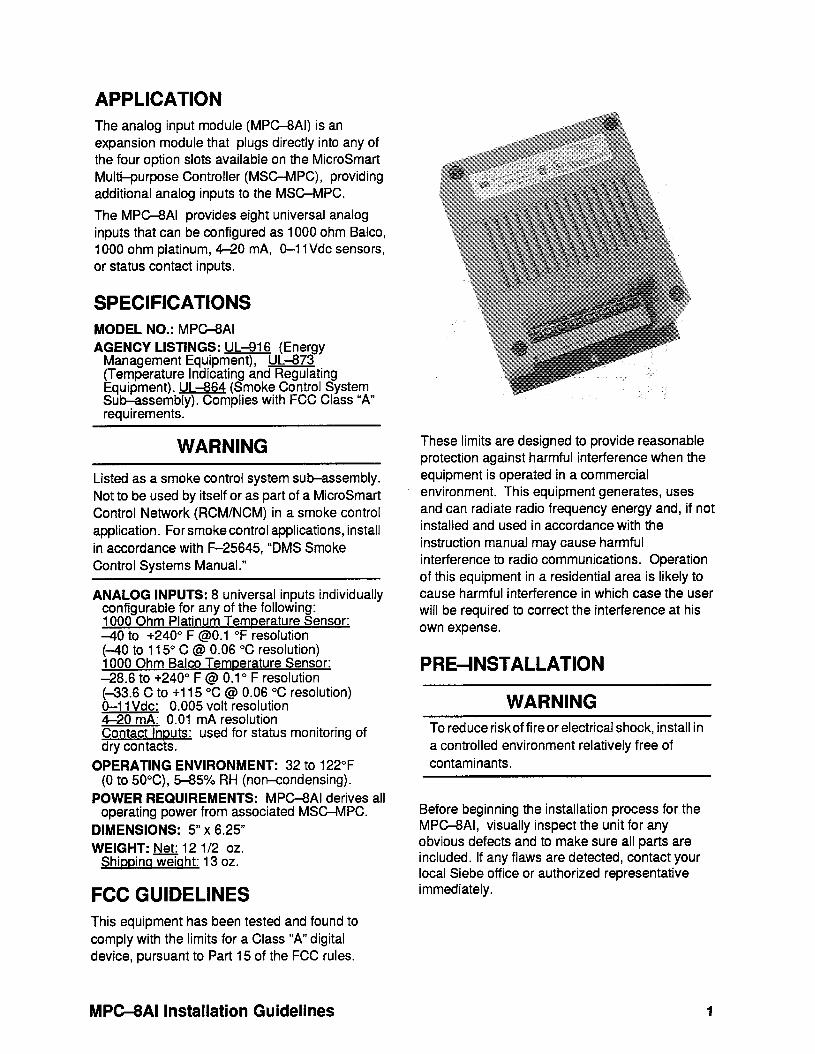
APPLICATION The analog input module (MPG8AI) is an expansion module that plugs directly into any of the four option slots available on the MicroSmart Multi-purpose Controller (MSCMPC), providing additional analog inputs to the MSGMPC.
The MPC-8AI provides eight universal analog inputs that can be configured as 1000 ohm Balco, 1000 ohm platinum, 4-20 mA, O-l 1 Vdc sensors, or status contact inputs.
SPECIFICATIONS MODEL NO.: MPC-8AI AGENCY LISTINGS: UL-816 (Energy
Management Equipment), UL-873 . (Temperature Indicating and Regulating Equipment). UL-864 (Smoke Control System Suhssembly). Complies with FCC Class “A” requirements.
WARNING
Listed as a smoke control system sub-assembly. Not to be used by itself or as part of a MicroSmart Control Network (RCM/NCM) in a smoke control application. For smoke control applications, install in accordance with F-25645, “DMS Smoke Control Systems Manual.”
ANALOG INPUTS: 8 universal inputs individually configurable for any of the following: 1000 Ohm Platinum Temperature Sensor: -40 to +240° F @O.l “F resolution (-40 to 115” C @ 0.06 “C resolution) 1000 Ohm Balco Temoerature Sensor: -28.6 to +240° F @ 0.1 o F resolution (-33.6 C to +115 ‘X @ 0.06 “C resolution) O-l 1 Vdc: 0.005 volt resolution 4-20 mA: 0.01 mA resolution Contact Inouts: used for status monitoring of dry contacts.
OPERATING ENVIRONMENT: 32 to 122°F (0 to 50X), 5-85% RH (non-condensing).
POWER REQUIREMENTS: MPC-8AI derives all operating power from associated MSC-MPC.
DIMENSIONS: 5” x 6.25”
WEIGHT: Net: 12 l/2 oz. Shiooinaweiaht: 13 oz.
FCC GUIDELINES This equipment has been tested and found to comply with the limits for a Class “A” digital device, pursuant to Part 15 of the FCC rules.
These limits are designed to provide reasonable protection against harmful interference when the equipment is operated in a commercial environment. This equipment generates, uses and can radiate radio frequency energy and, if not installed and used in accordance with the instruction manual may cause harmful interference to radio communications. Operation of this equipment in a residential area is likely to cause harmful interference in which case the user will be required to correct the interference at his own expense.
PRE-INSTALLATION
WARNING To reduce riskof fireor electrical shock, install in a controlled environment relatively free of contaminants.
Before beginning the installation process for the MPCBAI, visually inspect the unit for any obvious defects and to make sure all parts are included. If any flaws are detected, contact your local Siebe office or authorized representative immediately.
MPCXAI Installation Guidelines 1
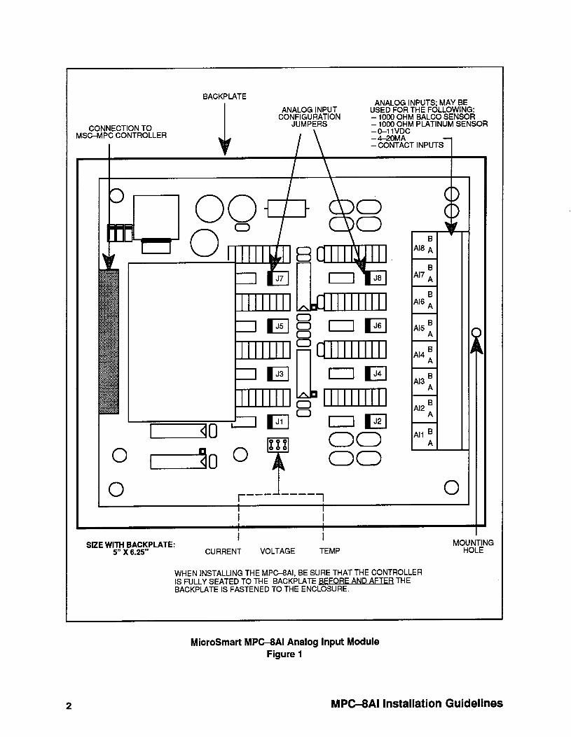
CONNECTION TO MSC-MPC CONTROLLER
I
BACKPLATE
ANALOG INPUT CONJ;;Flg;;lON
I\
ANALOG INPUTS; MAY BE USED FOR THE FOLLOWING: - 1000 OHM BALCO SENSOR IXIyf;d PLATINUM SENSOR
-4-20MA -CONTACT INPUTS 1
Al8 ;
B Al7 A
B Al6 A
A15 B
A
Al4 B
A
Al3 B A
Al2 B
A
r --- 1 ---- 1
I I
SIZE WiT$xB~;5~PLATE: I I
CURRENT VOLTAGE TEMP
WHEN INSTALLING THE MPG8AI, BE SURE THAT THE CONTROLLER IS FULLY SEATED TO THE BACKPLATE BFFORF AND AFTFR THE BACKPlATE IS FASTENED TO THE ENCLOSURE.
MicroSmart MPC-8AI Analog Input Module Figure 1
2 MPMAI Installation Guidelines

Programming information is contained in this document. For further details regarding software configuration, please refer to the appropriate User’s Guide and the MicroSmart Operator Interface User’s Guide.
INCLUDED IN THIS PACKAGE The MPC-8AI is supplied with:
1. One Nl-I 092 MPC-8AI module circuit board.
2. Two 8-pin connectors (green,N100-410659), for connection to analog inputs All -Al8.
OTHER COMPONENTS The MPCXAI requires direct connection to a MicroSmart MSC-MPC Multi-purpose controller.
OPTIONS AND ACCESSORIES T!S-5800 and TS-58000 series platinum RTD room thermostats and remote sensors, and TS-8100 and TS-81000 series Balco sensors. See separate platinum RTD room sensor data sheet for special models using RJ-11 jacks, adjustable setpoints, and pushbutton/LED overrides.
POWER REQUIREMENTS The MPCSAI is powered on when connected to a functional MSC-MPC. No additional power is required.
CAUTION
Disconnect power supply from associated MSC-MPC controller before installrng MPG ,$3igyt electrical shock and equipment
More than one disconnect switch may be required to de-energize this equipment before servicing.
Do not attempt to power the unit ON until installation is complete.
INSTALLATION
The MPC-8AI is a module that fits into any of the four option slots on the MSGMPC. To install, remove power from the MSCMPC and insert the MPC-8Al into the desired option slot on the MSC-MPC. Wiring instructions , diagrams, and software assignments are provided below.
NOTE
When installin the MPG8AI, be sure that the controller is fu i/ y seated to the backplate before and after the backplate is fastened to the enclosure.
SENSOR GROUNDING The shield wire for the room sensor should be grounded to chassis where the wire enters the enclosure. This ensures maximum protection from electrical noise and electrostatic discharge.
WIRING INSTRUCTIONS AND SETUP INFORMATION
Temperature Sensing Inputs The MPC-8AI allows two types of analog inputs for the purpose of temperature sensing . They are: - 1000 ohm platinum RTDs (-40 to +240” F) - 1000 ohm Balco RTDs (-30 to +240” F)
NOTE
T99 Series tern erature sensors cannot be used with the MP Gr? Al module.
MPMAI Installation Guidelines 3

Platinum RTD Inputs
The inputs provided for these sensors are terminals All A&B through Al8 A&B. The inputs are two+vire, twisted pair with shield.
Inputs are not polarized; terminate one of the wires to terminal A and the other wire to terminal B. Terminate the shield to cabinet ground closest to the entry point of the wire into the enclosure (cut off all additional wire). Cut and tape the shield at the sensor end to prevent it from coming in contact with junction box or other conductors. Refer below for wiring and setup information.
All -Al8 BELDEN
RFI-I 1000 OHM
GROUND SCREW ON ENCLOSURE CHASSIS
J# 1
JUMPER INFORMATION
2
3 TEMP
Platinum RTD or Balco Resistance Temperature Sensor
Figure 2
Table 1 below illustrates the numbering scheme and software assignments of the platinum RTD inputs. When making these assignments, the first entry is the option slot number on the connected MSC-MPC controller and the second entry is the number of the analog input being used.
For example, when plugged into option slot number 2, analog input number 1 has an assignment of Al 21.
INPNT = Al# (AS SHOWN BELOW) NOT
OPTION SLOT # ON THE MSC-MPC CONTROLLER
I
Al# t 1 .2 3 4 I
1000 OHM PLATINUM RTD ALPHA = 0.00375 (AMERICAN ALPHA)
SCALE OFSET CVTYP
SCALE OFSET CVTYP 1000 OHM PLATINUM RTD ALPHA = 0.00385 (EUROPEAN ALPHA)
OF-[ 0~
TS-5800 SERIES
SCALE OFSET CVTYP 1000 OHM BALCO Ts8000 SERIES OC
Software Assignments for Temperature Input Table 1
4 MPC4AI Installation Guidelines

Wirino Lenath Error
The elements SCALE and OFSET are used to convert the resistance reading to the proper engineering units. These elements also provide a method of calibrating the sensor’s displayed value to any desired value, thus correcting the system for any errors that may result from wire length or other variables.
Wiring length error can be eliminated by modifying the element OFSET. Because the resistance of the wire will be measured along with that of the sensor element, an error may result.
AWG 24 wire has a resistance of 17 ohms per thousand feet. If 50 feet of cable are used in a run, the resistance will be : 50’ x 2 (wires) x 17 ohms/l 000’ = 1.7 ohms.
The sensor has a sensitivity of approximately 2.2 ohms per degree. This 1.7-ohm error will result in a reading that is approximately .77 higher than the sensor would read if the wiring error were not present. To eliminate this error using the element OFSET, simply subtract .77 from the value given in the table for OFSET.
MPMAI Installation Guidelines 5
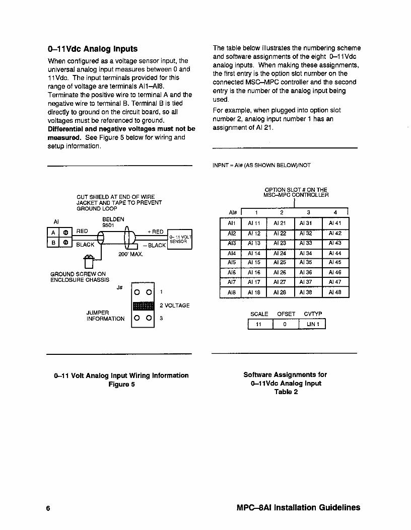
O-1 1Vdc Analog Inputs
When configured as a voltage sensor input, the universal analog input measures between 0 and 11 Vdc. The input terminals provided for this range of voltage are terminals All-A18. Terminate the positive wire to terminal A and the negative wire to terminal B. Terminal B is tied directly to ground on the circuit board, so all voltages must be referenced to ground. Differential and negative voltages must not be measured. See Figure 5 below for wiring and setup information.
The table below illustrates the numbering scheme and software assignments of the eight &l 1 Vdc analog inputs. When making these assignments, the first entry is the option slot number on the connected MSC-MPC controller and the second entry is the number of the analog input being used.
For example, when plugged into option slot number 2, analog input number 1 has an assignment of Al 21.
INPNT = Al# (AS SHOWN BELOW)/NOT
CUT SHIELD AT END OF WIRE JACKET AND TAPE TO PREVENT GROUND LOOP
GROUND SCREW ON ENCLOSURE CHASSIS
J#
I I 00’
JUMPER INFORMATION
2 VOLTAGE
3
OPTION SLOT # ON THE MSC-MPC CONTROLLER
Al# 1 1 2 3 4 I
1 Al7 1 Al 17 1 Al 27 1 Al 37 1 Al 47 1
Al8 Al 18 1 Al 28 1 Al 38 Al 48
SCALE OFSET CVTYP
11 0 LIN 1
O-l 1 Volt Analog Input Wiring Information Figure 5
Software Assignments for O-l 1Vdc Analog Input
Table 2
MPMAI Installation Guidelines

Calculating SCALE and OFSET Using MOCALC
MOCALC comes standard with the DOS Configuration Tool and is used to determine the proper values for SCALE and OFSET when provided with the desired values to be displayed from given input parameters. MOCALC is typically used to calibrate the display in engineering units in accordance with measurements taken. In some cases it can be used to correct for tolerance errors in input or output readings.
To use MOCALC, several parameters must be measured prior to running the program. First, the physical property to be measured or controlled is sampled near the high end of its scale and the corresponding bit value is recorded. Then another reading is taken with the property at the low end of its scale and the bit value displayed by the system is again recorded. Once this information is determined, the MOCALC program is able to calculate the appropriate values for SCALE and OFSET. Note that the characteristics of the variable must be linear to use MOCALC.
The sample calculations below are for a Belimo SM24 Actuator with the P500 feedback option that will be used to control a valve from 0 to 100 percent open.
For the point to be calibrated, set OFSET = 0 and SCALE = 4096.
With the feedback wired, drive the actuator/valve fully open (100%). Record the measured bit value displayed by the system for this point. This is the bit high value”. Next, drive the actuator/valve fully closed (0%). Record the measured bit value again. This is the “bit low value.”
1. From the CUCM directory, type MOCALC and press ENTER.
2. At the Enter Number prompt, type 1 to select Formulas for Scale and Ofset.
3. At the Enter Number prompt, type 6 to select Formulas for Bit High...Bit Low.
The program prompts you for the device range high and range low values. These values are the range of the points display, which in this case is from 0 to 100 percent (open). You will also need to enter the recorded bit values when’the actuator was driven to these two positions. MOCALC will then compute the proper SCALE and OFSET for the point to display linearly across the actuator’s travel range.
Please Enter Device Range High Value Number: 100
Please Enter Device Range Low Value Number: 0
Please Enter Recorded BIT HIGH Value Number: 3298
Please Enter Recorded BIT LOW Value Number: 517 SCALE: 147.28 OFSET: -18.59
In the example above, the desired display range for the actuator is 0 to 100 (percent open). The corresponding low and high bit values were recorded as 517 and 3298, respectively. MOCALC determined SCALE to be 147.28 and OFSET to be -18.59.
The formulas used by MOCALC are as follows:
SCALE = 4096 l (RANHI - RANLO) (BITHI - BITLO)
OFSET = RANLO (SCALE l BITLO) 4096
You are now ready to execute the MOCALC program.
MPC-8AI Installation Guidelines 7

&20 mA Inputs
Any of the universal analog inputs may also be configured as a 4-20 mA current signal input, as shown in Figure 6 below.
When configured as a 4-20mA input, an externally powered device must be used. The MPC-6AI does not provide panel power.
The table below illustrates the numbering scheme and software assignments of the eight 4-20mA analog inputs. When making these assignments, the first entry is the option slot number on the connected MSC-MPC controller and the second entry is the number of the analog input being used.
For example, when plugged into option slot number 2, analog input number 1 has an assignment of Al 21.
CUT SHIELD AT END OF WIRE JACKET AND TAPE TO PREVENT GROUND LOOP
INPNT = Al# (AS SHOWN BELOW)/NOT
Al BELDEN 4-20 mA
950h DEVICE
II) BLACK u BLACK
d
200’ MAX 24VDC + POWER _
I GROUND SCREW ON ENCLOSURE CHASSIS
J# 1 CURRENT
2
JUMPER INFORMATION
I I 00 3
I ,
OPTION SLOT # ON THE MSC-MPC CONTROLLER
Al# 1 1 2 3 4 I
1 Al7 1 Al 17 1 Al 27 1 Al 37 1 Al 47 1
Al8 Al 18 1 Al 28 1 Al 38 Al 48
4420 mA Wiring Information Figure 6
SCALE OFSET Cvp(P
20 0 LIN H
Software Assignments for 4-20 mA Analog input
Table 3
NOTE
To calculate SCALE and OFSET for these devices, use the MOCALC instructions covered previously in this document.
MPWAI Installation Guidelines

Contact Inputs
Any of the universal inputs on the MPC-8AI is capable of monitoring a single normally open or normally closed contact input (excluding pulse inputs). This input utilizes a 1 K ohm, l%, l&watt supervision resistor installed with the input device. The device is terminated to the appropriate Al connector terminals.
When Confiaured as a Normallv Ooen Contact Inr>ut
CUT SHIELD AT END OF WIRE JACKET AND TAPE TO PREVENT GROUND LOOP
All -Al8 BELDEN 1 K,l%
GROUND &EW ON ENCLOSURE CHASSIS
J#
JUMPER INFORMATION
Normally Open Contact Input Wiring Information
Figure 3
Conditions are as follows:
STOP when contact is open RUN when contact is closed TROUBLE when conductor is open
The software assignment required for the corresponding hardware address of the selected contact input is shown in Table 4 below.
INPNT = Al# (AS SHOWN BELOW)/REV/RUN
OPTION SLOT #ON THE MSC-MPC CONTROLLER
Al# 1 1 2 3 4 I
Al7 Al 17 Al 27 Al 37 Al 47
Al8 Al 18 Al 28 Al 38 Al 48
Assignments for Als used as Normally Open Contact Inputs
Table 4
MPCXAI Installation Guidelines 9
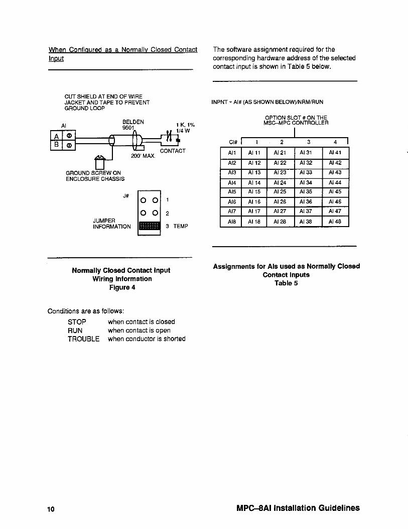
When Confiaured as a Normallv Closed Contact m
CUT SHIELD AT END OF WIRE JACKET AND TAPE TO PREVENT GROUND LOOP
GROUND S&W ON ENCLOSURE CHASSIS
J#
JUMPER INFORMATION
Normally Closed Contact input Wiring Information
Figure 4
Conditions are as follows:
STOP when contact is closed RUN when contact is open TROUBLE when conductor is shorted
The software assignment required for the corresponding hardware address of the selected contact input is shown in Table 5 below.
INPNT = Al# (AS SHOWN BELOW)/NRM/RUN
OPTION SLOT # ON THE MSC-MPC CONTROLLER
CI# I 1 2 3 4 I
All Al 11 Al 21 Al 31 Al 41
Al2 Al 12 Al 22 Al 32 Al 42
Al3 Al 13 Al 23 Al 33 Al 43
Al4 Al 14 Al 24 Al 34 Al 44
Al5 Al 15 Al 25 Al 35 Al 45
Al6 Al 16 Al 26 Al 36 Al 46
Al8 Al 18 Al 28 Al 38 Al 48
Assignments for Als used as Normally Closed Contact Inputs
Table 5
10 MPC-8AI Installation Guidelines

F-24853-3 BK
lnvensys Building Systems
1354 Clifford Avenue (Zip 61111) P.O. Box 2940
Loves Park, IL 61132-2940 United States of America
Printed in U.S.A.