fˆ ˙ ! ˆ˛ ˘ ˘$ˆ - ahdb cereals & oilseeds · draught forces –reduced wear and tear...
TRANSCRIPT
Field drainageguidePrinciples, installation and maintenance

F I E L D D R A I N A G E G U I D E2
Introduction
Slow downwarddrainage/percolationthrough small pores
More rapiddrainage viathe permeablebackfillconnectingthe flow tothe drain
WhatField drainage is installed to rapidly remove excess soil water
to reduce or eliminate waterlogging and return soils to their
natural field capacity. Drains can be used to control a water
table or to facilitate the removal of excess water held in the
upper horizons of the soil. A good drainage system will
reduce the risk of detrimental waterlogging to acceptable
levels.
Where soils are coarsely textured and well structured, the soil
may be freely draining enough to support field operations
and crop growth without the need for artificial drainage
systems. Field drains should be considered in the following
situations:
– Heavy clay soils: These are slowly permeable and, without
drainage, can be waterlogged for long periods, particularly
in areas of high rainfall
– Medium-textured soils in high rainfall areas: Drainage
may be needed to reduce vulnerability to compression,
slaking and compaction
– Light-textured soils: These soils are highly permeable but
drainage may be required to provide water table control in
low-lying areas
– Springs: Drains are used to intercept springs before they
reach the surface; this helps prevent erosion, localised
waterlogging and poaching, and the intercepted water, if
clean, may be used as drinking water for stock
There has been a general reduction in organic matter levels in
arable soils over the past 70 years. This makes them more
susceptible to waterlogging and more in need of drainage.
F I E L D D R A I N A G E G U I D E2
IntroductionHistory of field drainage in the UKAround 6.4 million hectares of agricultural land in England
and Wales have been drained with piped systems.
The rate at which land was drained increased rapidly
during World War II, as part of the drive to increase food
production, and peaked during the 1960s to 1980s, when
grant aid was available.
The cost of installationThe cost of installing a new comprehensive field
drainage system varies greatly according to the
scale and intensity of the system.
Based on 2015 prices, typical costs are around
£2,500–£3,500 per hectare for drainage with
permeable backfill and around £1,500–£2,500 per
hectare for drainage without permeable backfill.£
Drainage of heavy soils
Rise and fallof watertablemanaged bypipes alone
Water table control on permeable soils
What is field drainage?
Benefits to the farm businessIn some years, drainage can make the difference between having a crop
to harvest and complete crop loss; or whether or not the land can be
accessed to harvest the crop.
The benefits of field drainage to the farm business are substantial but
installation can be expensive. The magnitude of the benefit varies
considerably with climate, soil type and land use, so it is important to
carry out both environmental and cost-benefit assessments before
installing or managing field drainage systems.
Improved plant performanceDrainage is a long-term investment. Given good maintenance, a
useful life of at least 20 years can be expected and some
systems can last many decades longer.
Good field drainage reduces the peak surface water run-off rates
by increasing the availability of storm-water storage within the
soil. Rainfall then percolates down through the soil into the drains,
producing a more balanced flow after storms. This reduces the
risk of flooding and soil erosion not only within the field but also
further downstream in the catchment.
– Improved crop yield and quality
– More rapid warming of soils in spring, improving
germination
– Improved environment for soil organisms
– Better access to water and oxygen for plant roots
– Better crop uptake of soil mineral nitrogen

33
Identifying the needfor drainage 4
Soil management foreffective drainage
Identifying an existingdrainage system
Assessing an existingdrainage system
Maintenance andrepairs
Renewal andinstallation
Case studies
Glossary
6
8
10
12
16
20
22
Further information 23
Contents
Installation
(page 16)
Repair
(page 12)
Renewal
(page 16)
Maintenance
(page 12)
Is the soil
compacted?
(page 4)
Soil
management
(page 6)
Is the
drainage system
adequate?
(page 10)
YES
PAGE
Improvedspeed of work
and fuel use
Benefits to soil structureand the environment
Better accessto land
Q2
Q4
Is the soil
draining?
(page 4)
Q1
– Better traction
– Fewer
cultivation
passes
– Reduced
draught forces
– Reduced wear
and tear
– Fewer wet
areas to avoid
– Less structural damage to
soils
– Reduced frequency and
extent of livestock poaching
– Better water infiltration
– Reduced surface run-off and
erosion
– Reduced phosphorus and
pesticide losses to water
– Decreased potential for slug
activity and reproduction,
potentially reducing reliance
on metaldehyde
– Reduced duration/risk
of autumn
waterlogging
– Quicker accessibility of
fields following any
period of wet weather
– Crop inputs more likely
to be applied at
optimum time
– An extended growing
and grazing season
Reduced risks tolivestock health
– Reduced survival of
parasitic larvae
– Snails carrying liver
fluke do not thrive
– Footrot and foul-of-
the-foot are less
common
– Udder hygiene for
grazing stock is
improved
– Reduced risk of soil
contamination during
silaging operations
NO
NO
NO
NO
YES
YES
YES
Is there an
existing drainage
system?
(page 8)
Q3

Evidence of poor drainageThe evidence of poor drainage may be obvious in the form of surface ponding or saturated topsoils.
F I E L D D R A I N A G E G U I D E4
Identifying the need for drainage
Surface ponding Saturated topsoils
©ADAS ©ADAS
©ADAS ©ADAS
Prolonged waterlogging under the surface may not be so
obvious. Poor drainage conditions may be identified by:
– Poor crop health or yields: overlaying a yield map onto a
field drainage map can identify problem areas
– High surface run-off rates and soil erosion
– Limited field access without rutting or poaching (animal
hoof damage) compared with other fields in the area
– The presence of wet-loving plant species, such as common
rush and redshank
– Susceptibility to drought due to poor root development
and limited rainfall percolation into the soil
If drainage problems are widespread across the field, it may
be that:
– Soil management is not adequate
– No drains have been installed
– Mole drains need to be renewed
– In flatter fields, the outfall may simply be blocked
– The drainage system requires maintenance or has reached
the end of its useful life
Areas of grassland may become heavily poached
at times when soil conditions in other fields on
similar soils do not lead to poachingAreas within arable fields may be waterlogged,
resulting in crop loss or soil damage due to wheel ruts
EnvironmentSurface run-off may occur which can result in transport
of faecal material, sediment, soil-borne diseases (eg
clubroot), nutrients or agrochemicals to watercourses.

5
Natural pans – often very hard bands of soil
particles cemented together by iron and manganese
Saturated layer(perched water table)
Compact layer(pan)
Dry soils
Typicaldepth:
0.5 metres
Soil inspection pit extending below the compacted layer
Compaction pans – dense layers caused by farm
machinery operation; often 50–100 mm thick, they
generally have a platy structure and frequently
contain crop residues
Soil structure
Deep rooting indicates good structure Shallow rooting with many fine horizontal roots
and tap roots that are diverted horizontally
indicate the presence of compacted layers
Well-developed structure is evident from the ease
of digging and if the soil readily breaks down into
small structural units with many vertical fissuresSoils with poor structure are hard to dig and
break down into larger dense blocks, with poor
penetration by water, air and roots
Is the soil draining?Examining the soils to determine if they are naturally freely
or slowly draining or have damaged structure should be the
first action when drainage problems are suspected.
Without good soil structure, soil drainage will be poor,
whether it be by natural drainage or pipes.
Compacted layers can restrict surface water from reaching
underlying drainage systems. If compacted layers are
identified, remedial action should be undertaken to remove
them before considering field drainage maintenance or
reinstallation.
It is essential to routinely assess soil structure. This can easily
be incorporated into the farm soil sampling programme and
should be completed in spring or autumn.
Examine the soil at several points in the field to a depth of:
– Arable land: at least 600 mm
– Grassland: at least 500 mm
Soil colourGreyish-coloured soils and soils with rusty or grey-coloured
mottles are signs of poorer drainage.
Soil textureThe higher the clay content, the more likely the soil is to be
naturally poorly drained.
Root development
Perched water tableSoil compaction occurs when soil particles are compressed,
reducing the space (pores) between them. This restricts the
movement of vital air and water through the soil.
When soil water is present, dig a pit (to a depth where the soil
becomes drier) to aid diagnosis. Saturated soils overlying a
layer of dry soil after a period of heavy rain may indicate the
presence of a compacted layer preventing drainage.
It is not uncommon to find both naturally and artificially
compacted layers (pans) in susceptible soils. Plough pans can
develop if a field is repeatedly ploughed to the same depth.
If the pan, whether artificial or natural, is limiting water
infiltration and/or root growth, it should be removed by
subsoiling or topsoil loosening.

F I E L D D R A I N A G E G U I D E6
Soil management for effective drainage
Soil pit showing compacted soil layer (pan)
©ADAS
Winged subsoiler
Courtesy of Dick Godwin
Effective drainage relies on goodsoils managementIf soil examination identifies compacted layers that act as a
barrier to water movement, remedial action should be
undertaken to remove them before considering new drainage.
Maintaining good soils structure may avoid the need for
capital investment.
Minimise soil damage by reducing:
– Field trafficking
– Weight of machinery
– Tyre pressures
– Poaching of livestock
– Overworking of the seedbed
Other potential solutions include the use of low pressure
tyres, minimum tillage, controlled traffic farming and fixed
wheelings, avoiding turnout in poor soil conditions, and
considering the placement of livestock feeders and drinkers
and livestock tracks.
Subsoil and topsoil looseningWhen soils are wet, they are easily damaged by cultivation,
machinery traffic and livestock trampling. If the soil structure
has been damaged, subsoil or topsoil loosening (normally
referred to as 'subsoiling' and 'sward lifting', respectively) in
suitable conditions can be used to help restore the structure
of a damaged soil. It can also be used to improve subsoil
permeability.
Slit aerators can also be used in grassland fields but should
only target the top ten centimetres. Research has shown that
they can increase infiltration rates but good conditions are
needed below the target area or they can just move water
more quickly towards a drainage problem.
Operating notes1. Suitable conditions
Topsoil loosening and subsoiling should only be carried out
when the soil at working and loosening depth is in a 'dry' and
friable condition, so that it will shatter rather than smear.
Examine soils early in the operation to ensure effective
shattering is occurring.
For arable subsoiling, both the soil surface and the compacted
layer should be 'dry' to avoid soil structural damage.
For topsoil loosening in grassland using a 'sward lifter'-type
machine, the ideal conditions are when the soil surface is
slightly moist, to allow disc and tine leg entry while avoiding
excessive sward tear, and the lower topsoil is moist to dry, to
enable 'lift' and loosening.
2. Choice of soils loosening equipment
Winged subsoilers, developed in the 1980s, shatter the soil
much more effectively than conventional subsoilers. They
require higher draught force but can disturb a volume of soil
two to three times greater than a conventional subsoiler,
resulting in more effective disturbance.
The use of leading tines can
result in an increased volume
of soil disturbed without
increasing the draught but
they are not suitable for
grassland, as they cause
considerable surface
disturbance.
Topsoil looseners or ‘sward
lifters’ for grassland
incorporate a leading disc, a
vertical or forward-inclined leg
and a tine leg and a packer
roller behind to minimise
sward tear and surface
disturbance.Topsoil loosener for grassland
©Opico

7
Undisturbed soil
Initial field surface
Final soil surface
Disturbed soil
Tines too wide
Tines correctly set
50 mm
Drain
Blade/legPan or structureless layer
Permeablefill
FootTip/point
Direction of
subsoiler
Depth wheel
(if fitted)
Frame set horizontal
Rear packer
roller (if fitted)
Subsoiler operation
iFurther information:Think soils (Environment Agency)
www.gov.uk/managing-soil-types
Healthy Grassland Soils (AHDB)
www.healthygrasslandsoils.co.uk
A guide to better soil structure (Cranfield University)
www.landis.org.uk/downloads
3. Depth
It is best practice to use a depth wheel or rear packer roller to
maintain a constant tine depth.
Aim for tines to be about 25–50 mm below the base of the
compacted layer, up to a maximum depth of approximately
450 mm below ground level.
Maximum depth may be limited by shallow field drains, rock or
the critical depth of the tine (related to tine width and soil
conditions). Normal drain depth is around 700 mm below the
soil surface.
For subsoiling to result in improved drainage, the depth to which
the soil is loosened must be just greater than the depth down
to the top of the permeable backfill. This will connect the fissures
and allow water to move to the permeable fill over the drains.
4. Spacing between tines
– Conventional subsoiler: up to 1.5 times the tine depth
– Winged subsoiler: up to 2 times the tine depth
– With leading shallow tines: up to 2.5 times the tine depth
After a trial run, dig down and examine the effect. Spacing can
be adjusted, where possible, to achieve the desired degree of
soil disturbance.
5. Avoiding re-compaction
Recently loosened soils are very sensitive to re-compaction.
Avoid running over land that has already been subsoiled. In
grassland, avoid grazing after autumn loosening and cut rather
than graze in the first spring after treatment.
F I E L D D R A I N A G E G U I D E8
Identifying an existing drainage system
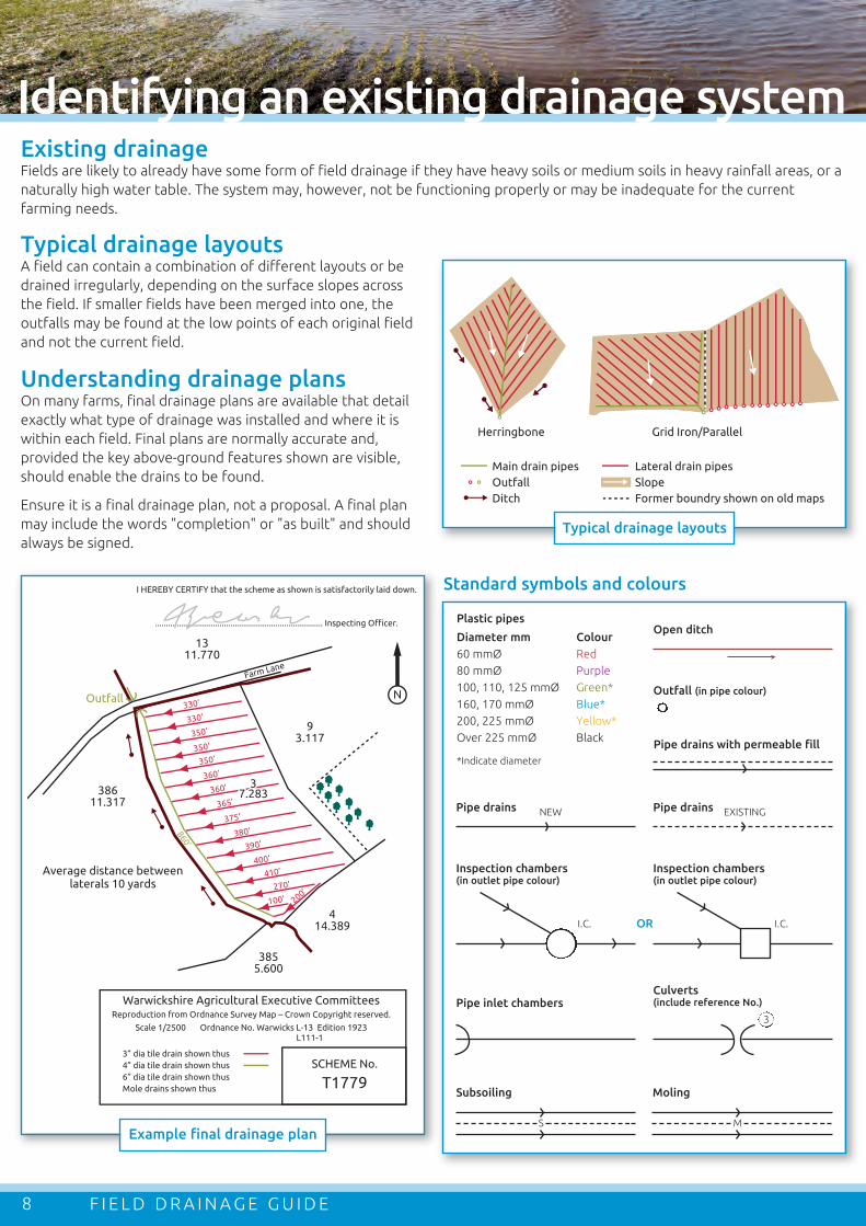
Example final drainage plan
93.117
N
38611.317
1311.770
Outfall
3855.600
414.389
330’
330’
350’
350’
350’
360’
360’
365’
375’
380’
390’
400’
410’
270’
100’ 200’
337.2837.283
37.283
860’
Average distance betweenlaterals 10 yards
Warwickshire Agricultural Executive CommitteesReproduction from Ordnance Survey Map – Crown Copyright reserved.
Scale 1/2500 Ordnance No. Warwicks L-13 Edition 1923 L111-1
3” dia tile drain shown thus4” dia tile drain shown thus6” dia tile drain shown thusMole drains shown thus
SCHEME No.
T1779
I HEREBY CERTIFY that the scheme as shown is satisfactorily laid down.
.............................................................................. Inspecting Officer.
Farm Lane
Herringbone
Main drain pipesOutfallDitch
Lateral drain pipesSlopeFormer boundry shown on old maps
Grid Iron/Parallel
Plastic pipes
Diameter mm Colour
60 mmØ Red
80 mmØ Purple
100, 110, 125 mmØ Green*
160, 170 mmØ Blue*
200, 225 mmØ Yellow*
Over 225 mmØ Black
*Indicate diameter
Pipe drains NEW
Inspection chambers(in outlet pipe colour)
Pipe inlet chambers
Subsoiling
I.C.
Pipe drains EXISTING
Inspection chambers(in outlet pipe colour)
Culverts(include reference No.)
I.C.
Open ditch
Outfall (in pipe colour)
OR
3
Typical drainage layouts
S
Moling
M
Pipe drains with permeable fill
Existing drainageFields are likely to already have some form of field drainage if they have heavy soils or medium soils in heavy rainfall areas, or a
naturally high water table. The system may, however, not be functioning properly or may be inadequate for the current
farming needs.
Standard symbols and colours
Typical drainage layoutsA field can contain a combination of different layouts or be
drained irregularly, depending on the surface slopes across
the field. If smaller fields have been merged into one, the
outfalls may be found at the low points of each original field
and not the current field.
Understanding drainage plansOn many farms, final drainage plans are available that detail
exactly what type of drainage was installed and where it is
within each field. Final plans are normally accurate and,
provided the key above-ground features shown are visible,
should enable the drains to be found.
Ensure it is a final drainage plan, not a proposal. A final plan
may include the words "completion" or "as built" and should
always be signed.
– Aerial photographs available online may reveal the lines
of the drains, although they may be confused with
other features, such as underground pipelines
– Slight linear depressions
may be visible on the field
surface
– The crop may vary in
quality or colour over the
line of a drain
– The soil may be drier
directly over the drain
than between drains
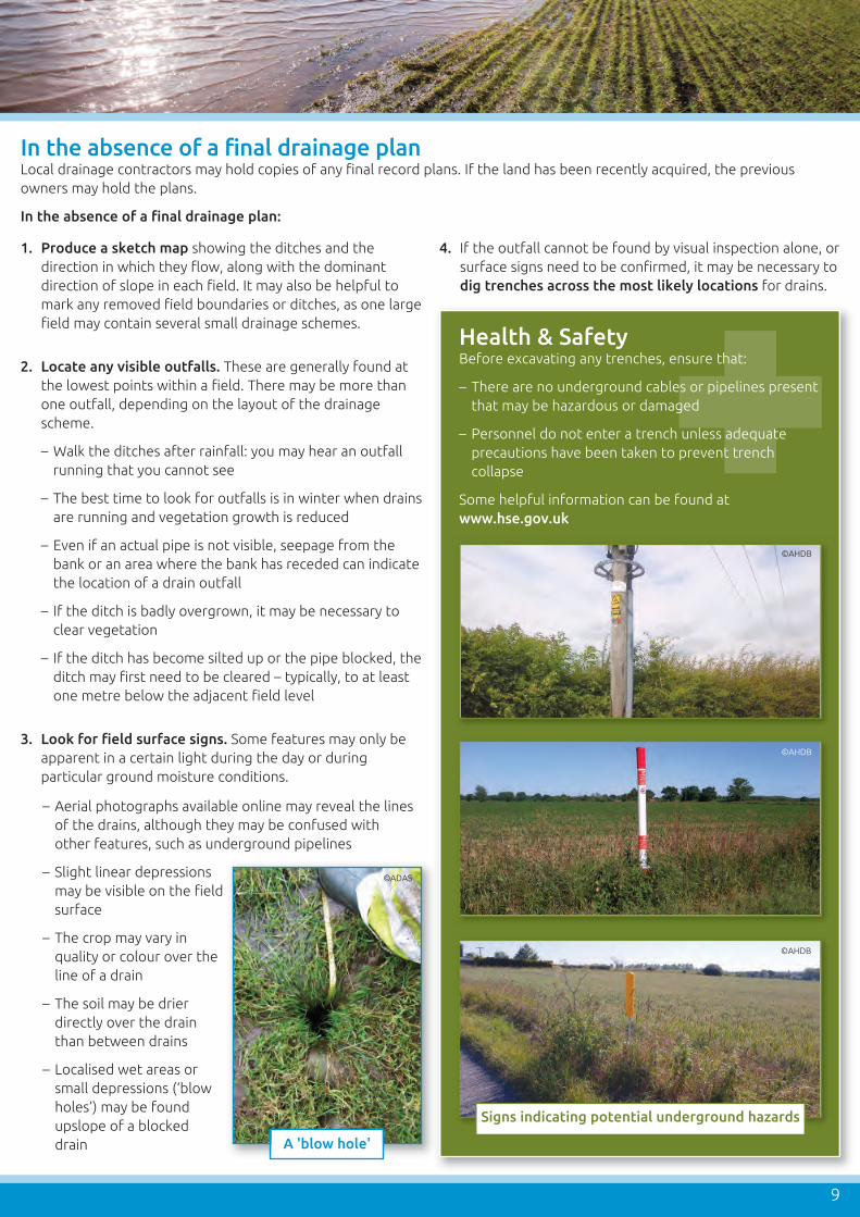
– Localised wet areas or
small depressions (‘blow
holes’) may be found
upslope of a blocked
drain
9
A 'blow hole'
Signs indicating potential underground hazards
©AHDB
©ADAS
©AHDB
©AHDB
1. Produce a sketch map showing the ditches and the
direction in which they flow, along with the dominant
direction of slope in each field. It may also be helpful to
mark any removed field boundaries or ditches, as one large
field may contain several small drainage schemes.
2. Locate any visible outfalls. These are generally found at
the lowest points within a field. There may be more than
one outfall, depending on the layout of the drainage
scheme.
– Walk the ditches after rainfall: you may hear an outfall
running that you cannot see
– The best time to look for outfalls is in winter when drains
are running and vegetation growth is reduced
– Even if an actual pipe is not visible, seepage from the
bank or an area where the bank has receded can indicate
the location of a drain outfall
– If the ditch is badly overgrown, it may be necessary to
clear vegetation
– If the ditch has become silted up or the pipe blocked, the
ditch may first need to be cleared – typically, to at least
one metre below the adjacent field level
3. Look for field surface signs. Some features may only be
apparent in a certain light during the day or during
particular ground moisture conditions.
4. If the outfall cannot be found by visual inspection alone, or
surface signs need to be confirmed, it may be necessary to
dig trenches across the most likely locations for drains.
In the absence of a final drainage planLocal drainage contractors may hold copies of any final record plans. If the land has been recently acquired, the previous
owners may hold the plans.
In the absence of a final drainage plan:
Health & SafetyBefore excavating any trenches, ensure that:
– There are no underground cables or pipelines present
that may be hazardous or damaged
– Personnel do not enter a trench unless adequate
precautions have been taken to prevent trench
collapse
Some helpful information can be found at
www.hse.gov.uk
F I E L D D R A I N A G E G U I D E10
Assessing an existing drainage system
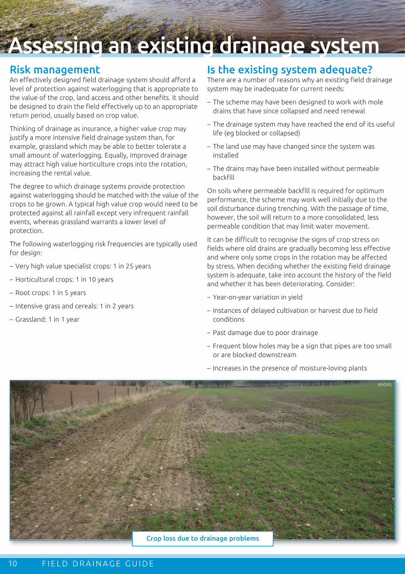
Crop loss due to drainage problems
©ADAS
Is the existing system adequate?There are a number of reasons why an existing field drainage
system may be inadequate for current needs:
– The scheme may have been designed to work with mole
drains that have since collapsed and need renewal
– The drainage system may have reached the end of its useful
life (eg blocked or collapsed)
– The land use may have changed since the system was
installed
– The drains may have been installed without permeable
backfill
On soils where permeable backfill is required for optimum
performance, the scheme may work well initially due to the
soil disturbance during trenching. With the passage of time,
however, the soil will return to a more consolidated, less
permeable condition that may limit water movement.
It can be difficult to recognise the signs of crop stress on
fields where old drains are gradually becoming less effective
and where only some crops in the rotation may be affected
by stress. When deciding whether the existing field drainage
system is adequate, take into account the history of the field
and whether it has been deteriorating. Consider:
– Year-on-year variation in yield
– Instances of delayed cultivation or harvest due to field
conditions
– Past damage due to poor drainage
– Frequent blow holes may be a sign that pipes are too small
or are blocked downstream
– Increases in the presence of moisture-loving plants
Risk managementAn effectively designed field drainage system should afford a
level of protection against waterlogging that is appropriate to
the value of the crop, land access and other benefits. It should
be designed to drain the field effectively up to an appropriate
return period, usually based on crop value.
Thinking of drainage as insurance, a higher value crop may
justify a more intensive field drainage system than, for
example, grassland which may be able to better tolerate a
small amount of waterlogging. Equally, improved drainage
may attract high value horticulture crops into the rotation,
increasing the rental value.
The degree to which drainage systems provide protection
against waterlogging should be matched with the value of the
crops to be grown. A typical high value crop would need to be
protected against all rainfall except very infrequent rainfall
events, whereas grassland warrants a lower level of
protection.
The following waterlogging risk frequencies are typically used
for design:
– Very high value specialist crops: 1 in 25 years
– Horticultural crops: 1 in 10 years
– Root crops: 1 in 5 years
– Intensive grass and cereals: 1 in 2 years
– Grassland: 1 in 1 year

11
Assessing the costs and benefits of field drainage
Positive points
The impact of field drainage on pollution riskThe relationship between field drains and pollution can be contradictory.
Negative points
Points to consider– Best practice should
always be followed
when applying
manures, fertilisers and
agrochemicals to avoid
losses via surface run-
off or field drains
– Organic manures
should not be applied
to land within 12 months of pipe
or mole drainage installation
– Organic manures should not be
applied to drained land when soils
are wet and drains are running
– Organic manures should not be
stored within ten metres of a
field drain
!Maintaining good field
drainage and good soil
structure reduces
waterlogging
When soils are wet or dry with
deep cracks and rain falls within a
few days of agrochemical
application...
Drains are most effective at
providing a conduit for
agricultural pollutants when
newly installed or in fields
with deep cracking clays
...field drains
can provide a rapid route
for water enriched with
ammonium, phosphorus,
pesticides, fine sediment or
other associated pollutants
This reduces the likelihood of
causing soil compaction
through untimely field
operations
This decreases surface run-
off, soil erosion and the loss
of sediment and associated
pollutants, such as
phosphorus, to water
While field drainage can have economic, practical and
environmental benefits, installation can be expensive.
Drainage can also exacerbate water pollution and impact
negatively on some habitats. It is, therefore, important to
carry out an environmental and cost:benefit assessment
before installing or carrying out maintenance on field drainage
systems.
Production benefits resulting from drainage are most likely to
be obtained in areas of high rainfall or on:
– Heavy clay soils, especially where arable or intensive
livestock production is practised
– Medium soils where potatoes, other root crops, or high
value crops are grown
– Low-lying permeable soils where the groundwater level
comes close to the land surface in winter or after rainfall
In many cases, it is better for both agricultural production and
the environment to remove excess water by field drainage but
there are cases when the production benefits are outweighed
by the costs and there are opportunities to mitigate climate
change, flooding, protect water quality or create wildlife
habitats by allowing field drainage to deteriorate.
Waterlogged land may be low value agriculturally but it may
have biodiversity benefits or help to reduce flooding risk.
Sacrificing an area of waterlogged land may reduce costs by
acting as a sediment trap and reducing the need for costly
activities, such as watercourse dredging. Suitable areas where
drainage might be allowed to deteriorate could include land
adjacent to watercourses, natural wetlands and ribbon areas
at the base of steep slopes, particularly on intensive grassland
on heavy soils in the centre and west of the UK.
For more information for farmers in priority areas at risk of
water pollution, contact Catchment Sensitive Farming:
www.gov.uk/catchment-sensitive-farming
EnvironmentIn the Mires on the Moors project (a partnership between
South West Water, two National Park Authorities and
other organisations, such as the Environment Agency),
drainage ditches on Dartmoor and Exmoor were blocked
to restore peatland. This increases the carbon and water
storage on the moor and slows the flow of water off the
moor so that storm and flood damage is reduced,
sediment settles out and drinking water quality is
improved.
www.exmoormires.org.uk
F I E L D D R A I N A G E G U I D E
Maintenance and repairs
12
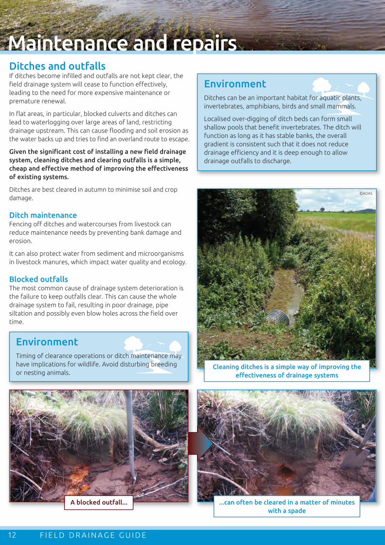
A blocked outfall... ...can often be cleared in a matter of minutes
with a spade
Cleaning ditches is a simple way of improving the
effectiveness of drainage systems
©ADAS
©ADAS©ADAS
Ditches and outfallsIf ditches become infilled and outfalls are not kept clear, the
field drainage system will cease to function effectively,
leading to the need for more expensive maintenance or
premature renewal.
In flat areas, in particular, blocked culverts and ditches can
lead to waterlogging over large areas of land, restricting
drainage upstream. This can cause flooding and soil erosion as
the water backs up and tries to find an overland route to escape.
Given the significant cost of installing a new field drainage
system, cleaning ditches and clearing outfalls is a simple,
cheap and effective method of improving the effectiveness
of existing systems.
Ditches are best cleared in autumn to minimise soil and crop
damage.
Ditch maintenanceFencing off ditches and watercourses from livestock can
reduce maintenance needs by preventing bank damage and
erosion.
It can also protect water from sediment and microorganisms
in livestock manures, which impact water quality and ecology.
Blocked outfallsThe most common cause of drainage system deterioration is
the failure to keep outfalls clear. This can cause the whole
drainage system to fail, resulting in poor drainage, pipe
siltation and possibly even blow holes across the field over
time.
EnvironmentDitches can be an important habitat for aquatic plants,
invertebrates, amphibians, birds and small mammals.
Localised over-digging of ditch beds can form small
shallow pools that benefit invertebrates. The ditch will
function as long as it has stable banks, the overall
gradient is consistent such that it does not reduce
drainage efficiency and it is deep enough to allow
drainage outfalls to discharge.
EnvironmentTiming of clearance operations or ditch maintenance may
have implications for wildlife. Avoid disturbing breeding
or nesting animals.

PipesBlockage by tree or hedge rootsWhen designing the drainage system, trees and hedges
should be avoided wherever possible. When this is not
possible, a sealed pipe should be used for any pipes within a
tree rooting zone or within 1.5 metres of a hedge.
If a blockage occurs, it may be possible to dig up the pipe on
one or both sides of the blockage and use rods to clear the
roots but the section of pipe will often need to be replaced
with a sealed pipe.
Pipe siltationIf drain outfalls are left
submerged or blocked for a
long period of time, siltation
of the pipes may occur. This
can be difficult or impossible
to remedy.
Other than as a result of
damaged or blocked pipes,
siltation most commonly
occurs on fine sandy and fine
silty soils.
If pipe siltation is not too
severe, it may be possible to
rod the drains clear or to
employ a contractor with
specialist drain jetting equipment.
Where pipe siltation is a naturally recurring problem, a
drainage system with separate outfall pipes for each drain is
best. This allows easier access for cleaning operations.
13
Drainage outfall blocked by ochre
Replacing field drainsWhen replacing a field drain, the same diameter (or metric
equivalent) drain should be used as the drain being
replaced. If the drain is a carrier drain or culvert, increasing
the pipe diameter would reduce the risk of blockage or
excess flows collapsing the pipe in the future; however,
care may be needed to avoid increasing flood risk
downstream. Expert advice should be sought if in doubt.
EnvironmentTake care to avoid unnecessary damage to tree
roots or disturbing archaeological remains.
©ADAS
Silted clay drain
©ADAS
Drain jetting
©Mastenbroek
OchreOchre is a generic term used to describe deposits that form in
drains when soluble iron leaching out of the soil in drainage
water comes into contact with air and is oxidised, at which
point it becomes insoluble. It can also be caused by bacterial
growths that secrete iron.
In some cases, a drainage scheme may fail completely due to
ochre accumulation. In these cases, redrainage is only
worthwhile if future ochre development is unlikely.
Preventing ochre formation:
– Soils rich in iron may be prone to ochre and there is little
that can be done to prevent ochre formation
– There are methods that attempt to prevent the build-up of
ochre but these can be specialist, intensive and often not
very successful
Removing ochre:
– Regular rodding or jetting may remove the ochre
– If the pipe slots or permeable fill is blocked, the benefits
may be limited or nil
Design:
– Where ochre is a problem, systems with separate outfall
pipes for each drain are best, as they allow easier access for
clearance operations

F I E L D D R A I N A G E G U I D E
Maintenance and repairs
14
A long beam gives a molewith a consistent gradient,parallel to the soil surface
Unlike for subsoiling, the soil at working depth needsto be sufficiently plastic to form a stable channel
Direction ofmole plough
The soil above the moleshould be dry enough toavoid damage, give goodtraction and encouragefissuring
Bullet
500
– 60
0 m
m
Expander
Appropriate conditions for forming mole drains
Clay
Clay loamSandy clayloam
Silty clayloam
Silt loamSandy silt loamSandy loamLoamy
sandSand
Sandyclay
Siltyclay
Increasing sand (2–0.06 mm)
Incr
easi
ng c
lay
(less
than
0.0
02 m
m) Increasing silt (0.06–0.002 m
m)
Heavy soils
Sandy andlight siltysoils
Medium soils
Soil texture classification
Source: Controlling soil
erosion (Defra, 2005)
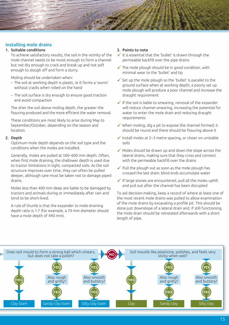
Is the moist soil predominantlyrough and gritty?
Does soil mould to form an easily deformedball and feel smooth and silky (butter)?
Is it difficult toroll into a ball?
Does soil feel smoothand silty as well as gritty?
Does soil stainfingers?
Sand Loamy sand Sandy loam Sandy silt loam Silt loamSource: Controlling soilerosion (Defra, 2005)
NO
NO
YES NO
NO
NO
YES
YES YES
YES
START
Moisten adessert-
spoonful of soilgradually,kneading
thoroughly,until soil
crumbs arebroken down.
Mole drainsMole drains are unlined channels formed in a clay subsoil. They
are used when natural drainage needs improving in particularly
heavy or calcareous clay subsoils that would require
uneconomically closely spaced pipes for effective drainage.
Mole drains act as closely spaced pipe drains and conduct
water to the permanent pipe drains or direct to open ditches.
Mole drains are not suitable for controlling rising
groundwater or areas prone to flooding.
Soils should have a minimum of 30% clay for best results. Clay
gives the soil the ability to hold together and reduces the
chances of the channel collapsing after the mole is pulled.
Sand content should be less than 30%. The soil should be free
of stones at the mole drain depth.
Mole drains are formed by dragging a ‘bullet’ (effectively, a
round-nosed cylindrical foot shaped like a bullet with slight
tapering towards the tail) followed by an expander (a
cylindrical plug of slightly larger diameter than the bullet)
through the soil to form a circular semi-permanent channel –
ie a natural pipe with fissuring in the soil above the channel.
How long do mole drains last?The longevity of mole drains depends on a number of factors,
including:
– Soil texture (high clay content is better)
– Soil calcium content (high levels of calcium will increase
longevity)
– Climate (wetter conditions will reduce longevity)
– Slope (too shallow or too steep will reduce longevity)
– The moisture conditions in which the moles were formed
Mole channels in very stable, clay soils (clay content ~45%)
can last over ten years but the method can still be effective in
soils with at least 30% clay, particularly calcareous soils.
Typical lifespan in suitable soils ranges from five to ten years
but it can be reduced where patches of sandier soil occur,
leading to premature collapse. Bad soil management can seal
off the routes by which water reaches the mole drains.
If the pipe drainage system was designed to be
supplemented by mole drains, it is good practice to renew
mole drains on a cycle of around once in every five years.
15
Does soil mould to form a strong ball which smears,but does not take a polish?
Soil moulds like plasticine, polishes, and feels verysticky when wet?
Also roughand gritty?
Also smoothand buttery?
Also roughand gritty?
Also smoothand buttery?
Clay loam Sandy clay loam Silty clay loam Clay Sandy clay Silty clay
YES
YES
YES
YES
NO
YES
YES
YES
YES
YES YES
Installing mole drains1. Suitable conditions
To achieve satisfactory results, the soil in the vicinity of the
mole channel needs to be moist enough to form a channel
but not dry enough to crack and break up and not soft
enough to slough off and form a slurry.
Moling should be undertaken when:
– The soil at working depth is plastic, ie it forms a ‘worm’
without cracks when rolled on the hand
– The soil surface is dry enough to ensure good traction
and avoid compaction
The drier the soil above moling depth, the greater the
fissuring produced and the more efficient the water removal.
These conditions are most likely to arise during May to
September/October, depending on the season and
location.
2. Depth
Optimum mole depth depends on the soil type and the
conditions when the moles are installed.
Generally, moles are pulled at 500–600 mm depth. Often,
when first mole draining, the shallower depth is used due
to tractor limitations in tight, compacted soils. As the soil
structure improves over time, they can often be pulled
deeper, although care must be taken not to damage piped
drains.
Moles less than 400 mm deep are liable to be damaged by
tractors and animals during or immediately after rain and
tend to be short-lived.
A rule of thumb is that the expander to mole-draining
depth ratio is 1:7 (for example, a 70 mm diameter should
have a mole depth of 490 mm).
3. Points to note
It is essential that the ‘bullet’ is drawn through the
permeable backfill over the pipe drains
The mole plough should be in good condition, with
minimal wear to the 'bullet' and tip
Set up the mole plough so the 'bullet' is parallel to the
ground surface when at working depth; a poorly set up
mole plough will produce a poor channel and increase the
draught requirement
If the soil is liable to smearing, removal of the expander
will reduce channel smearing, increasing the potential for
water to enter the mole drain and reducing draught
requirements
When moling, dig a pit to expose the channel formed; it
should be round and there should be fissuring above it
Install moles at 2–3 metre spacing, or closer on unstable
soils
Moles should be drawn up and down the slope across the
lateral drains, making sure that they cross and connect
with the permeable backfill over the drains
Pull the plough out as soon as the mole plough has
crossed the last drain: blind ends accumulate water
If large stones are encountered, pull all the moles uphill
and pull out after the channel has been disrupted
To aid decision-making, keep a record of where at least one of
the most recent mole drains was pulled to allow examination
of the mole drains by excavating a profile pit. This should be
done just downslope of a lateral drain and, if still functioning,
the mole drain should be reinstated afterwards with a short
length of pipe.

F I E L D D R A I N A G E G U I D E
Renewal and installation
16
Factors to consider when designing a new drainage systemDrain depthIn slowly permeable soils, research has shown that (unless
there is a specific crop need) lateral drain depths greater than
0.75 metres give no additional benefit. Drains simply need to
be deep enough to avoid damage from soil implements.
In permeable soils, where the drains control the depth of
the water table, deeper drains allow the spacing between
drains to be increased. Drain depths in such soil types are
typically 1.2–1.5 metres.
Maximum drain depth is often limited by the depth of the
ditches or watercourses into which the drains discharge.
These can be deepened but only to the level of the
downstream channel.
Drain spacingDrain spacing has always varied according to local custom but
it has become more standardised in recent years. The correct
spacing can be calculated using theoretical equations but this
is not often done in practice.
In heavy clay soils, the theoretical correct drain spacing will
almost always be so small as not to be economically viable.
Where soil conditions are appropriate, wide-spaced drains with
permeable backfill supplemented with mole drains are the
best choice. Pipe drain spacing for a mole drainage system can
be as wide as 80 metres, although 40 metres is more typical.
The main limiting factors are soil stability and landform.
On land with soils not suitable for moling, a modern system
would have a spacing of 20–25 metres with permeable backfill
over the drains. The effectiveness of this type of system will
rely greatly on maintaining good soil structure, sometimes
aided by subsoiling.
If permeable backfill is not used, drain spacing in the region
of 10 metres will be needed but this is unlikely to be as
effective as a scheme using permeable backfill.
In permeable soils with a rising groundwater, the drain
spacing will be determined by the depth of the drains and the
level at which the groundwater is to be controlled and
permeable backfill is not usually needed.
Outfall availability and gradientOutfall availability and gradient have an impact on the
efficiency of the drainage system. As a comparison, a
bath/shower is designed to slope and has a strategically
positioned plug hole (outfall) to drain the water. Lack of
available outfall and/or gradient to enable water to drain
away materially affects the efficiency of the field drainage
system.
Drain diameterIn the UK, drain diameters are calculated using the procedures
set out in MAFF/ADAS Reference Book 345 (The design of
field drainage systems). This method takes account of:
– Soil type and slope: speed of water movement
– Land use: the degree of risk that is acceptable depending on
the crop value
– Climate: rainfall intensity
– Type of drainage system; for example, mole drains must not
be left submerged for more than 24 hours and, therefore,
excess water must be evacuated rapidly
The rainfall figures used in the method set out in MAFF/ADAS
Reference Book 345 are now outdated and in some areas may
not match current rainfall patterns. They also take no account
of potential future increases in storm intensities due to
climate change. However, these remain the current
guidelines.
Use of permeable backfillPermeable backfill refers to the gravel/stone chippings
applied to the trench above the drain, typically to the base of
the topsoil.
The use of permeable backfill has been a long-debated subject,
primarily due to the significant associated cost. There are many
examples of very old drainage systems without permeable
backfill that still have some function; however, research
indicates that on drained clay soils without permeable backfill,
while the drains may initially function well, the permeability of
the soil in the drain trench decreases with time.
Best practice is to install sufficient permeable backfill so that
a connection exists between the drain trench and the
cultivated layer. As a minimum, the permeable backfill layer
should connect with the mole drains
or any fissures caused by subsoiling.
If mole drains are to be installed
over the pipes, the use of permeable
backfill is essential to provide a
hydraulic connection between the
mole channels and the drain.
The performance of drains installed
without permeable backfill cannot
be rejuvenated by subsoiling.
The one circumstance where
permeable backfill is never required
is where the function of the
drainage is to control a rising water
table in a coarsely textured soil.Permeable backfill in
trench over drain
©ADAS

17
Moles drawn toeven gradient
Mole spacing close enoughto disturb area between:usually 2–3 m apart
Pipes large enough tocarry flow from moles
Allow sufficient distancebetween drain and fieldboundary for mole ploughto reach working depth(generally 10–15 yards)
Pipe spacing dependenton soil type and slope offield: generally between20 and 100 metres
Good ditch outlet to ensurethat moles are never submerged
A well laid pipe drainsystem is essential as anoutlet for the moles
Ditch
Mole channels deep enough tobe in good clay avoid damage bycultivations and achievemaximum fissuring
Permeable fill overpipes to provideconnection for moles
Mole drain
Drain positioned adjacent to sandierpocket to provide outlet for moledrain and prevent prematurecollapse of the mole in sandier soil
Pipe drain
MolMolM es es s dradradd wn wn n totoeveeven gn gradraddienientt
MolMole se se pacpaccp ingingni cl closeose en enougoughhto to disdisi turturu b ab a rearea be be b twetwew en:en:usuusuallally 2y 2y –3 –3 3 m am am parparpa tt
PipPipes es larlarl ge ge e enoenooughugh to to t carcarry ry flowflow fr from om molmoleses
AllAllow ow suffisuffifficiecient nt n disdistantant cececbetbetweeween dn drairaiin an a nd nd fielfiele ddboubouundandary ry forforr mo mo o ole le ploploughughhto to reareach ch worworkinking dg deptepthh(ge(genernerallally 1y 10–10–15 y5 yardards)s)
PipPipPi e se spacpaca inging de de d penpenp dendend tton on o soisois l tl typeypep an and sd sloplope oe offfielfield: d: gengeneraerallylly be betwetweenen20 20 andand 10 100 m0 metretreses
GooGood dd ditcitch oh outlutlet et t to to ensensureurerssthathat mt moleolees as a re re nevnever er subsubbmermergedgedg dgbb
A wA wellell la laid id pippipe de drairainnsyssystemtem is is es essensentiatial al as as annyy s s
tt f f r tr the he molmolesessoutoutu lelel ttt tt f f r tr the he momooutoutletlettl t fo fo r r r
DitDitD chchh
MolMolM e ce c hanhanh nelnels ds deepeep en en e e ougough th t oo d d oobe be e in in n googood cd claylay av av oidoido da da d magmagm e be b byyyy culculu tivtivatiatit onsons an and ad achichieveeve a amaxmaxm imuimum fim fissussurinringgg fi fiss
PerPermeameableble fil fill ol oververpippipes es to to proprovidvideeconcono necnectiotioon fn for or molmolesesese
MolMole de drairaiaia nniinniiii
djadjacencenc nt tt t to so so andandierierDraDrain in djadjacciioneoned ad a ddin in pospositiitioneoned d DraDrai i pr provioviov de de outouto tletletet fo for mr m oleoleketket to to pr pr p ooo d d k tketk pocpockkkpocpockkpp
dradrain in andand pr pr reveevee nt nt preprer matmatmn n ddradrad in in ddd atatureureecolcolc laplapse se s of of thethe mo mole le e in in sasasansanndiedied r sr soiloil
PipPipe de drairainn
Layout of piped drainage and mole drains
EnvironmentA new drainage scheme can provide an opportunity to
create new conservation features. Old farm ponds that
have silted up could be reopened to provide a habitat and
catch pit for eroding soils, and ditches could be over-dug
into localised ponds.
Government-funded schemes may be available for a range
of land management options and capital items that can be
used to reduce the negative impacts of field drainage on
water quality or to create/improve wetlands and ditch
habitats. These include the creation of wet grassland,
ditch management and buffering of water bodies. For
more information, see
www.gov.uk/guidance/countryside-stewardship-manual
SiteField drainage should be planned carefully to avoid negative
impacts on water bodies used for drinking water abstraction,
fisheries or Sites of Special Scientific Interest (SSSIs) sensitive
to raised nitrate levels. Field drains and outfalls could be
designed to discharge into a wetland buffer area before
flows enter a watercourse or be directed away from sensitive
water bodies. Field drains should not be installed within at
least ten metres of a slurry or silage store.
Sustainable Drainage Systems (SuDS) or novel approaches,
such as bioreactors, can be used with field drainage systems
to trap sediment and slow water/soil run-off and to filter
pollutants in drainage water.
EnvironmentNew outfalls should be positioned sensitively at ditches
and ponds to avoid damaging habitat. Land drains should
not divert water away from areas that may depend on this
water for drinking, washing or habitat. Diverting flows can
also increase the risk of flooding and infrastructure failure.

F I E L D D R A I N A G E G U I D E
Renewal and installation
18
Selecting a designerBefore engaging an independent field drainage consultant, it
is important to determine if they have adequate experience
and qualifications. A specialist designer will have a thorough
understanding of the needs and management of the soils, as
well as of field drainage.
To enable them to determine if a new drainage system is
required or whether maintenance of the existing system
and/or improved soil management may be adequate to
resolve the problem, a designer should always:
Discuss any problems you have with the site and how you
intend to manage the site in the future
Survey the soil types, soil conditions, existing drainage
systems, field topography, proximity to utility services and
other features that may affect the final design
Consider potential environmental impacts, drainage law
and economic feasibility
Given the scale of the investment that a new drainage system
represents, it is recommended that independent advice is
sought with regard to the design.
Using an experienced consultant designer will ensure that
the scheme is the best and most economically appropriate
to meet the requirements.
Selecting a contractorTo install a new comprehensive field drainage system, it is
essential to employ a specialist land drainage contractor
with access to specialist machinery that can install and
backfill drains rapidly. A drainage machine shapes the trench
bed and can set a consistent gradient, even in the flattest of
fields. A specialist contractor should fully understand field
drainage requirements and employ the approved standards
and materials.
The Land Drainage Contractors Association (LDCA) is a trade
association and has a list of members on its website
(www.ldca.org.uk) which can be a useful starting point for
selecting a contractor. Not all drainage contractors are
members of the LDCA, however. Recommendations from
others in the local farming community can be another
helpful source of information.
Contractors may have different approaches to dealing with
the scale, access and physical aspects of the location, so
quotes may vary.
Land drainage lawA landowner has an obligation to accept the natural flows
of water from adjoining land and must not cause any
impedance to these flows that would cause injury to
adjoining land. "Natural water flows" refers to water that has
not been diverted from its natural path, artificially increased
or had the run-off flow rate changed (eg, by the construction
of unauthorised paved areas within the catchment).
This means that if a landowner neglects or fills in their ditch,
such that water may not freely discharge from higher
neighbouring land, the landowner is guilty of causing a
nuisance. In this situation, the landowner or occupier of the
higher land may ask the Agricultural Land Tribunal to make
an order requiring the landowner guilty of nuisance to carry
out the necessary remedial works. It must be emphasised,
however, that it is usually far better to attempt to resolve
such situations by amicable discussions with the offending
party first, as they may be unaware of the nuisance.
If the neglected ditch in question runs directly along the
boundary between respective ownerships, the assumption
that would be made is that the owner of the original hedge
is also the owner of the ditch. On watercourses, the
ownership boundary is assumed to be down the middle of
the bed. Only clear evidence to the contrary, such as the
deeds to the land, will rebut this assumption.
No ditch or watercourse should be piped, filled in, restricted
or diverted without the approval of the regulatory
authority, for example, the local authority or the EA, NRW,
SEPA, NIEA, or the local Internal Drainage Board. Consent
may be needed for works within 8–10 metres of the bank
top of a watercourse. Uncultivated or semi-natural land is
protected under the Environmental Impact Assessment
Regulations (Agriculture) and should not be drained without
prior approval from the relevant national body.
Health & SafetyIt is advisable to request:
– From the contractor:
– A Risk Assessment and Method Statement (RAMS)
– Verification that they have sufficient public liability
insurance cover
– From the designer:
– Verification that they have sufficient professional
indemnity insurance cover
EnvironmentArchaeological features can be damaged by field drain
installation and drains may conflict with the conservation
of a wetland or water habitat or species. Where relevant,
contact Natural England, the drainage authority or a
county archaeologist before commencing work.

19
Modern plastic land drainage pipe
Washed gravel permeable fill over drain Single wall pipe wrapped in geotextile
Precast concrete headwall (type K)
©ADAS©ADAS
©ADAS
©Polypipe Civils
©ADAS
Standards, materials and qualityThere are two fundamental standards to which any designer will be working:
– Reference Book 345: The design of field drainage pipe systems (MAFF/ADAS, 1982)
– Technical Note on Workmanship and Materials for Land Drainage Schemes (ADAS, 1995)
Pipe typeCurrently, all new drainage schemes are installed using
plastic pipes, although many older schemes were installed
with clay pipes and may be replaced with the same.
It is essential that a material designed for use in field
drainage is used.
Consideration should be given to the use of twin-wall or
ductile iron pipes or gravel pipe surround where there is a
risk of pipe crushing.
Permeable backfill type– The material used must be hard and durable when wet
and when dry
– The bulk of the material should be in the range 5–50 mm
– The material should not contain more than 10% fines
Outfall typeMost modern outfalls are installed with glass-reinforced
concrete headwalls; however, the actual outfall type may
vary according to its location.
Filter wrap Filter wrap is a geotextile barrier around the outside of
the pipe to prevent soil particles entering the drain. It is
not commonly used in the UK, as research has shown that
pipe sedimentation is not usually a problem if the pipes
have been laid and maintained properly. There are,
however, some cases with fine, sandy soils when filter
wrap can be beneficial.
Filter wrap should never be used where there is a risk
of ochre.
Within these primary standards, there will be a number of
decisions to be made about the design specification:

F I E L D D R A I N A G E G U I D E20
Case studies
£?
!
Cost
Benefits
£2,417
£229 - £25= = 12 years
Molescroft Farm, Beverley, East YorkshireThe farm– 485 ha farm with deep loam and alluvial clay soils
– Land is at or below 5 metres above sea level and suffers from waterlogging
– Arable cropping: wheat, barley, oilseed rape, field beans and vining peas
– 10% of the farm is in Higher Level Stewardship and grazed by cattle and sheep
The outcome– New drainage has made the field far easier to work
and manage
– It was the highest yielding field in the following
harvest year
– Lower inputs of herbicides were required
The cost The total cost of the upgrade was £14,500 (£2,417/ha).
Maintenance costs estimated at approximately 1% of
capital cost (£25/ha/year)
Benefits estimated at a total of £229/ha/year:
– Typical yield increased from 7 t/ha to 8.75 t/ha, a total
of £175/ha/year
– Herbicide costs were reduced by £30/ha/year
– Better soil structure reduced subsoiling costs by 25%,
saving £3/ha/year, and cultivation costs by
£21/ha/year
Simple payback period
The problemThe problem field had a full tile drainage system installed
in the 1980s, but:
– Wet patches had started to appear
– Crops had to be drilled early to avoid soil damage and
poor establishment
– The cost of weed control had increased due to the lack
of opportunity for stale seedbeds
– Recent wet seasons had resulted in patchy crops with
increased weed problems and soil damage
The main drain was found to be completely blocked by
willow roots and some tiles were misaligned.
The solutionThe solution was to drain a 6 ha area of the field, with
new plastic pipes installed between the existing tiles and
gravel backfill used to improve effectiveness. CommentOnce the investment has been paid off, the benefits
may continue to be received for many years (provided
maintenance is sustained).
These calculations assume average changes to costs
and returns; however, extreme weather will have a far
greater effect. It is difficult to factor in random
occurrences, such as the avoidance of significant crop
loss due to waterlogging, and the decision to invest in
drainage should be made on a field-by-field basis. The
costings do not take into account the cost of finance or
increased land value.

21
£?
!
Cost
Benefits
£5,245
£595 - £52 - £132= = 13 years
Evershot Farms Ltd, Melbury Osmond, DorsetThe farm– 1,500 ha farm, largely on heavy, poorly drained soils
– Rainfall is over 1,000 mm/year
– Stocking: 900 cows and 2,500 mule ewes; heifers are contract reared off the farm
– Cropping: mainly grassland with about one third cut for silage; maize is no longer grown
– The farm has a 750 kW biogas plant
The outcome– Soil problems are now avoided and increased rainfall
infiltration minimises run-off
– The field is accessible two weeks earlier and for two
weeks longer
– The Italian rye-grass has increased yield (from 37 t/ha
to 45 t/ha) and forage value
– Reduced risk to operations and increased forage
quality and dry matter yield
The cost The total cost of the drainage was £5,245/ha (£48,500
for the drainage, plus £5,000 on ditching), plus
maintenance at £52/ha and additional annual silage
making costs of £132/ha.
Benefits estimated at a total of £595/ha/year:
– The change from maize to grass silage has produced
a higher dry matter yield and greater forage value
from four cuts
– The change to Italian rye-grass resulted in an increase
in forage value
– Cultivation savings:
– Moving to grass, the cultivation savings were
£105/ha/year
– The average annual cost of moling was the same
as subsoiling
– Forage savings (total of £490/ha) from:
– Increased value of silage (at previous yield level):
37 t/ha at £4/t gives £148/ha
– Increased yield of silage: 8 t/ha at £34/t gives
£272/ha
– Value of additional grazed forage: £70/ha
Simple payback period
The problemThe aim is for cows to be turned out in late March
and housed from mid-September but the grazing
season can be very variable from year to year.
Maize was causing significant soil damage.
The solutionThe solution was to replace maize with Italian rye-grass,
introduce whole-crop wheat to balance the ration (and
save on purchased straw) and drain a 10.2 ha field,
including:
– A main drain with laterals and headwalls at outlets
– Digging out the ditches downstream to obtain
sufficient fall
– Moling to increase connectivity every five years at
reseeding
CommentOnce the investment has been paid off, the benefits
may continue to be received for many years (provided
maintenance is sustained).
These calculations ignore the potential for extreme
weather, without drainage, to result in significantly
lower forage yields, soil damage and increased housing
and forage requirements. Wet conditions during silage-
making can result in contamination from soil, leading
to poor fermentation, poor milk yield and potential
health problems. The costings do not take into account
the cost of finance or increased land value.

F I E L D D R A I N A G E G U I D E
Glossary
22
Compaction: The process by which the soil density increases due to trafficking or soil working when conditions are unsuitable, ie too wet.
Culvert: A short length of pipe installed to allow access over the ditch or watercourse.
Drain jetting: Removal of deposited sediment from a drain using a high pressure water jet.
Field capacity: The moisture content of the soil after excess water has drained away.
Filter wrap: A geotextile barrier wrapped around the pipe to prevent particles entering the pipe.
Friable: Soil where the aggregates crumble easily into smaller ones.
Infiltration: The capacity of the soil to absorb rainfall.
Laterals: The drains installed, usually parallel to each other, to intercept soil water and transport flows to the main drain.
Mains: Drains installed to collect the water from a number of laterals and transport it to the ditch.
Outfall: Point at which the main drains or individual laterals discharge into a ditch.
Percolation: The process of water moving down through the soil to depth.
Perched: Kept at a raised level above that which gravity induced drainage would otherwise allow.
Perforateddrainage pipe: Drainage pipe used to collect water from the soil and which is slotted to allow the entry of water.
Poaching: Damage to the soil surface caused by animal hooves.
Slaking: The collapse of the soil aggregates as the soil wets up rapidly.
Water table: The saturated zone of the soil.
Video demonstrating the principles of subsoilingAHDB Pork has produced a series of videos demonstrating the
general principles of subsoiling as part of their Practical Pig
App. They look at cultivation depth, choice of machine and the
effects of tines and wings. practicalpig.ahdb.org.uk

Further information
23
Agriculture and Horticulture Development Board (AHDB)Improving soils for Better Returns (2013)
beefandlamb.ahdb.org.uk/returns/nutrition-and-forage
Healthy grassland soils: www.healthygrasslandsoils.co.uk
Good soil management practice: A guide for outdoor pig keeping (2014)
pork.ahdb.org.uk/environment-buildings/water-soil-and-air
Soil management for potatoes (2013)
potatoes.ahdb.org.uk/growing/soil
Other sources of informationCatchment Sensitive Farming: www.gov.uk/catchment-sensitive-farming
Catchment Sensitive Farming Officers provide free advice and support to farmers in priority catchments to reduce water
pollution. This includes information on soil and water management and a review of field drainage.
Land Drainage Contractors Association (LDCA): www.ldca.org
Think soils (Environment Agency): www.gov.uk/managing-soil-types
A guide to better soil structure (Cranfield University): www.landis.org.uk/downloads
Geographic information for Great Britain: www.magic.gov.uk
Scottish soils database and website: preview.scottishsoils.aea.com
Countryside stewardship manual (Natural England): www.gov.uk/guidance/countryside-stewardship-manual
Environmental permits for flood defence: www.gov.uk/flood-defence-consent-england-wales
River maintenance and drainage charges: farmers and landowners:
www.gov.uk/river-maintenance-and-drainage-charges-farmers-and-landowners
Flood and coastal erosion risk management R&D (Environment Agency): evidence.environment-agency.gov.uk/FCERM
Pinpoint best practice information sheets (The Rivers Trust): www.theriverstrust.org/pinpoint/info_sheets.html
Constructed farm wetlands: A guide for farmers and farm advisers in England (Wildfowl and Wetlands Trust):
www.wwt.org.uk/farmwetlands
Sustainable drainage systems: Maximising the potential for people and wildlife (RSPB and Wildfowl and Wetlands Trust):
www.wwt.org.uk/suds
Godwin, R. J. and Spoor, G. (2015) Choosing and evaluating soil improvements by subsoiling and compaction control.
In Ball, B. C. and Munkholm, L. J. (eds). Visual Soil Evaluation: Realising Potential Crop Production with Minimum Environmental
Impact. CABI, Wallingford, UK (in press).

This guide, funded by all six divisions of the Agriculture
and Horticulture Development Board (AHDB) and with a
contribution from the Catchment Sensitive Farming
initiative, was written by Kirk Hill, Robin Hodgkinson,
David Harris and Dr Paul Newell Price, ADAS.
AHDB is grateful to many people who have
commented on draft versions of the guide, including:
Dr Liz Genever, AHDB Beef & Lamb; Dr Susannah Bolton,
Jo Crowley, Fiona Geary, Dr Paul Gosling, Harry
Henderson and Dr Simon Oxley, AHDB Cereals &
Oilseeds; Dr Debbie McConnell, AHDB Dairy;
Dr Jim Dimmock, Dr James Holmes, Dr Jon Knight,
Dr Anne Stone and Andrew Tinsley, AHDB Horticulture;
Nigel Penlington, AHDB Pork; Jenny Bashford and
Dr Philip Burgess, AHDB Potatoes; Phillippa Mansfield,
Catchment Sensitive Farming; James Davies and
Rachel Dils, Environment Agency; Rob Burtonshaw,
Farm Services Ltd; Prof. Dick Godwin, Soil and Water
Management Centre, Harper Adams University;
members of the LDCA; Peter Gadd and George Lawrie,
AHDB Cereals & Oilseeds R&KT Committee members.
Acknowledgements
Edited by Dr Emily Boys, AHDB Cereals & Oilseeds.
Photographs courtesy of ADAS, Mastenbroek, Opico
and Polypipe Civils.
Summer 2015
Produced by AHDB Beef & Lamb, AHDB Cereals & Oilseeds, AHDB Dairy,
AHDB Horticulture, AHDB Pork and AHDB Potatoes
Electronic version can be downloaded at cereals.ahdb.org.uk/publications
© Agriculture and Horticulture Development Board 2015
All rights reserved
Agriculture and Horticulture Development BoardStoneleigh ParkWarwickshireCV8 2TL
While the Agriculture and Horticulture Development Board seeks to ensure that the information contained within this document is accurate at the
time of printing, no warranty is given in respect thereof and, to the maximum extent permitted by law, the Agriculture and Horticulture
Development Board accepts no liability for loss, damage or injury howsoever caused (including that caused by negligence) or suffered directly or
indirectly in relation to information and opinions contained in or omitted from this document.
Reference herein to trade names and proprietary products without stating that they are protected does not imply that they may be regarded as
unprotected and thus free for general use. No endorsement of named products is intended, nor is any criticism implied of other alternative, but
unnamed products.
Publications orders0845 245 [email protected]