f b-series, au-outline gawn series and kaplan series
TRANSCRIPT
International Journal of Applied Engineering Research ISSN 0973-4562 Volume 13, Number 6 (2018) pp. 4067-4075
© Research India Publications. http://www.ripublication.com
4067
Comparative Analysis of B-Series, Au-Outline Gawn Series and Kaplan
Series Propeller on Trimaran Ship using Computational Fluid Dynamics
Method
Berlian Arswendo Adietya1 1 Naval Architecture Department, Engineering Faculty, Diponegoro University, Semarang, Indonesia.
Hartono2
2 Industrial Engineering Department, School of Vocation, Diponegoro University, Semarang, Indonesia.
Adry Zakky1 1 Naval Architecture Department, Engineering Faculty, Diponegoro University, Semarang, Indonesia.
Aulia Windyandari2
2 Industrial Engineering Department, School of Vocation, Diponegoro University, Semarang, Indonesia. Author for correspondence: Aulia Windyandari, ST. MT.,
Abstract
The propeller on a trimaran vessel requires some special
criteria such as large thrust value, low-pressure value, and a
smooth flow of propellers. This study has focused on the
comparison of three types of propellers namely B-series, Au-
Outline Gawn Series, and Kaplan series by considering some
aspects of propeller diameter, number of blades, skew angle,
and pitch. The numerical analysis was made by using
Computational Fluid Dynamics (CFD) program to evaluate
the performance of the propeller configurations. The result
shows that Kaplan Series have the thrust value of 455628 N,
the torque value of 96456.6 Nm, the pressure average value of
18608.92 Pa. According to the numerical results, it can be
concluded that Kaplan series have a better performance
compares with AU-Outline Gawn Series and B-Series for the
Trimaran Ship.
Keywords: B-series propeller, AU Outline Gawn series
propeller, Kaplan Series Propeller
INTRODUCTION
Indonesia is an archipelagic country which has a wide water
area and potential as one of supporting economic growth. One
of the most important means of transportation in supporting
the economy in the field of transportation is the ship.
The Trimaran is a Multihull ship. Multihull ship is a type of
ship that has a hull more than one hull, therefore, Trimaran
means to have 3 pieces of the hull. Such a design can raise the
Center of Gravity and the Center of Buoyancy so as to have
high stability, [1]. In addition to the Center of Gravity and the
Center of Buoyancy, speed is also greatly noted in multihull
ship design. Therefore, the type of propeller that can produce
a good ship speed but with a small vibration is preferred.
The types of propellers will be analyzed using the CFD
method to find out whether the experimental test and the CFD
are not much different and also know the most effective and
efficient type of propeller in its use on a trimaran vessel.
The types of propellers used in the comparison are Au-Outline
gawn series, B-Series, and Kaplan series. This comparison is
aimed to determine the level of matching on ship KRI
Klewang I.
Considering the subject matter of the background, several
problem formulations can be taken as follows.
Determination of the magnitude of the resulting
thrust, on the propeller blade and the turbulent flow
form of each trimaran ship propeller design
Comparison of thrust, pressure and torque
performance from B-Series propeller variations, Au-
Outline Gawn Series, and Kaplan.
Determination of the most effective type of propeller
in its use on trimaran vessels with variations
available.
Based on the above background then the purpose of
this study are:
To know the value of thrust, streamline, and pressure
that occurs on each type of trimaran ship propeller.
To find out the comparison of the variation of B-
Series propeller, Au-Outline Gawn Series, and
Kaplan on a trimaran ship.
To obtain optimum propeller type to improve
trimaran ship efficiency
International Journal of Applied Engineering Research ISSN 0973-4562 Volume 13, Number 6 (2018) pp. 4067-4075
© Research India Publications. http://www.ripublication.com
4068
LITERATURE REVIEW
Trimaran Ship Propeller
In the development of the propeller undergoes some form of
modification in order to get the most appropriate model as a
ship propulsion tool. The most important requirement for a
trimaran ship propeller is the high speed required but with a
fairly small vibration since trimaran is usually used as a
speedboat. Therefore, it is feared that cavitation causes
vibration and performance reduction.
Propeller B-Series
Propeller B-Series or better known as Wageningen is a
propeller that is often used primarily for ship merchant ship
type. The shape of the B-Series propeller is very simple. This
propeller has a modern section and good performance
characteristics. Generally, B-Series propellers have variations
[2]:
H/D 0,5 - 1,4
Z 2 - 7
AE/Ao 0,3 - 1,05
Propeller Au-Outline
This Au-outline type propeller is the result of the development
of "AU type Aerofill" by conducting testing with the
systematic series test method. This type of propeller has a
better performance than the previous type, both in terms of
efficiency, cavitation, and vibration of the propeller. The
diagram design of the experimental results of this series has
been used for the planning of modern ship propellers.
Kaplan Propeller
Kaplan's propeller is a propeller using axial flow reaction.
This type of Kaplan is arranged like a propeller on a boat. The
propeller usually has 3 to 7 blades.
In a similar way to a power generator turbine, the Francine
turbine, the Kaplan of which works by reaction principle. This
Kaplan propeller has a road wheel similar to an airplane
propeller.
Hydrodynamics of Propeller.
Hydrodynamics is an event where the velocity between the
top and bottom of the hydrofoil occurs differently. The fluid
passing through the top of Hydrofoil travels faster than the
fluid passing through the bottom. This is due to the difference
in pressure between the upper fluid flow and the lower fluid
flow. As we know that the amount of pressure is inversely
proportional to the magnitude of the speed.
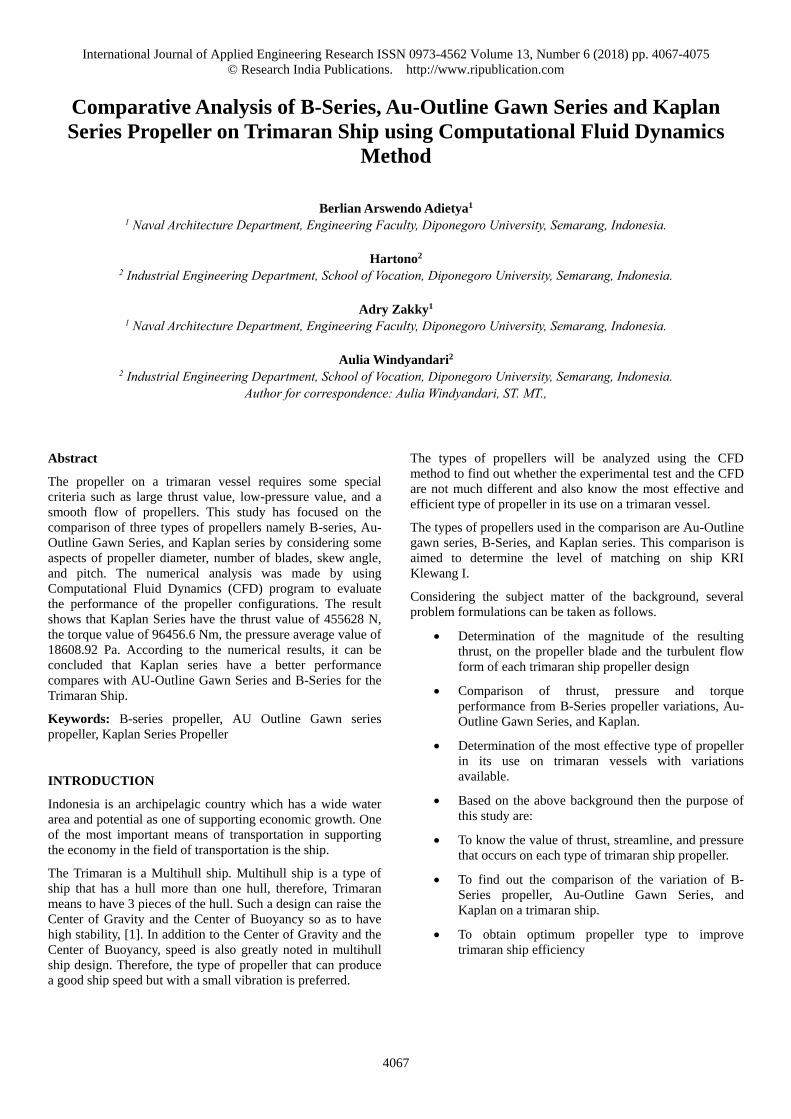
Figure 1. Forces of propeller foil
Geometry of Propeller
The surface of the rear-facing vane is called the side of the
face, or face, (face) or high-pressure side, while the opposite
side is called the back or the back side, or the low-pressure
side, [3].
The simplest form of high side pressure is a helical surface.
This surface can be defined as a surface formed by a straight
line, called a generator or generator line (generatrix, or line
generator) that revolves around an axis passing through one
end and simultaneously moving along the axis. The axial
distance traveled in each range is called the step or the spacing
distance of P (pitch). If the screwing step is fixed then it
means that P for all radius in the vane is thus the same, [4].
The Characteristics of Propeller
The propeller load characteristics can be presented with a
graph of several coefficients in the form of sizes. In general,
the characteristics of the ship's propeller under open water test
conditions are represented in the KT diagram (Thrust
coefficient) - KQ (Torque coefficient) - J (Advanced
coefficient). The equation model of ship propeller
performance is as follows:
KQ 2 4
Qn D
(1)
J VanxD
(2)
KT 2 4
Tn D
(3)
Where:
KT = Thrust coefficient
KQ = Torque coefficient
J = Advanced coefficient
Va = Advanced velocity
D = Diameter of propeller
n = Propeller revolution

International Journal of Applied Engineering Research ISSN 0973-4562 Volume 13, Number 6 (2018) pp. 4067-4075
© Research India Publications. http://www.ripublication.com
4069
T = Thrust of propeller
Q = Torque of propeller
ρ = Density of fluids
For the value of propeller efficiency in open water is given the
formula:
0 2
TxVax xnxQ
(4)
0 2
JKTKQ
(5)
Skew Angle Propeller
The propeller develops several modifications of the slash, the
skew propeller, in which the shape of the propeller is
somewhat tapered on its part, the skew angle propeller itself
has the sense that the angle between propeller shaft center line
up to blade tip. The blade tip itself is the encounter of the
trailing edge and leading edge on the surface propeller and is
the maximum distance of the propeller radius. Skew on
propeller can serve to reduce load and propeller pressure when
fluid flows break, [5].
Skew on the propeller itself is divided into two types: biased
skew (skew bias) and balanced skew (balanced slope).
Figure 2. Skew Angle propeller
Figure 3. Balanced skew
Figure 4. Biased skew
Blade Area Ratio
Blade Area Ratio or BAR is the ratio of the vane leaf area to
the full blade tip rotation area or commonly referred to as A0.
In reality, there are 3 BAR types, namely: Projected Area,
Developed Area, and Expanded area
Figure 5. Type Blade Area Ratio.

International Journal of Applied Engineering Research ISSN 0973-4562 Volume 13, Number 6 (2018) pp. 4067-4075
© Research India Publications. http://www.ripublication.com
4070
To some extent the propeller area has the following equation:
A0 = π D2
4 (6)
(7)
Computational Fluid Dynamics (CFD)
Computational Fluid Dynamics (CFD), is one of the branches
of fluid mechanics that uses numerical methods and
algorithms to solve and analyze problems related to fluid flow.
The purpose of the CFD is to predict accurately the flow of
fluids, heat transfer, and chemical reactions in complex
systems, involving one or all of the above phenomena. This
technique is very useful and can be applied in industrial and
non-industrial fields. There are several advantages of CFD
based on an experimental approach to fluid system design,
among others:
Minimize the cost and time of designing a product, if
the design process is done with an experimental test
with high accuracy.
Has the ability of a study system that can control
experiments that are difficult or impossible through
experimentation.
Have the ability to study systems under hazardous
conditions at or beyond critical tipping points
(including safety studies and accident scenarios).
In the design work, the existing problems need to be described
into the CFD software by describing the model and also the
determination of boundary conditions. Furthermore, in the
solver, the problem will be calculated by Navier Stroke
equation approach. From the calculation results than obtained
the output of the running program CFD. Computational Fluid
Dynamics consists of three main elements, [7]:
Pre Processor
The pre-processor includes input from flow problems to a
CFD program and the transformation of the input to a form
suitable for use by the solver.
Solver Manager
The solver can be divided into three types, namely finite
difference, finite element, and spectral method.
Post Processor
Post-processor is the stage of visualization of the previous
stage. Postprocessors are growing with the advancement of
engineering workstations that have great graphics and
visualization capabilities.
PROPELLER MODELING
The main data size of the propeller is processed using
propeller modeling software which is propeller coordinate
processing software.
Figure 6. Propeller modeling Software
Primary size data propeller processed using propeller
modeling software Furthermore, made a 3D model to be
processed into solid objects before putting to the analysis, 3D
modeling using the 3d solid work software.
Figure 7. 3D Modeling Software
The next stage is the geometry where the model is checked
whether the model is solid. Then the boundary is formed on
the x-axis z plane and the definition of each boundary section
such as inlet, outlet, and wall settings.
Figure 8. Geometry Stage
Next is the meshing stage to determine the size of each
element and set the detail through the size of the elements we
use.
International Journal of Applied Engineering Research ISSN 0973-4562 Volume 13, Number 6 (2018) pp. 4067-4075
© Research India Publications. http://www.ripublication.com
4071
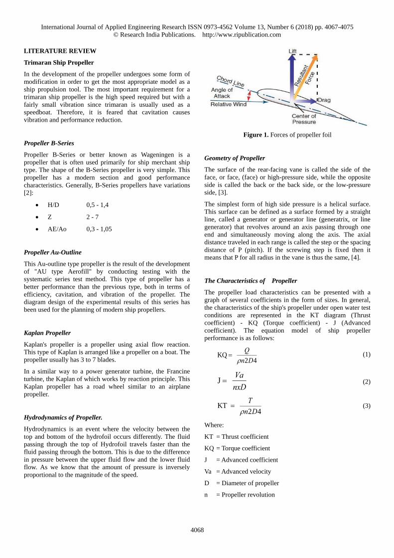
Figure 9. Mesh Stage
Next, we set each criterion we use by setting the Set-up. The
set-up used is a criterion that has been in the previous
validation so get results that have errors not far from the
results of research that has been done. The following Domains
Physics are used.
Table 1. Domain Default
Domain - Default Domain
Type Fluid
Location B342
Materials Water
Fluid Definition Material Library
Morphology Continuous Fluid
Settings Buoyancy Model Non Buoyant
Domain Motion Rotating
Angular Velocity [rev min^-1]
Axis Definition Coordinate Axis
Rotation Axis Coord 0.1
Reference Pressure 1.0000e+00 [atm]
Heat Transfer Model Isothermal
Fluid Temperature 2.5000e+01 [C]
Turbulence Model k epsilon
Turbulent Wall Functions Scalable
Here is a picture of the set-up settings in the boundary that
have been created in the previous stage.
Figure 10. Boundary Set-up
The solution stage is the stage where the boundary that has
been given the criterion is done an iteration to get the
convergence result.
Figure 11. Convergence model
The final stage is the post-stage where we get the results that
can be simulated either 3D or 2D.
Figure 12. Result model
Table 2. Comparison of test results with CFD simulation
Rotation
Speed (rpm)
Experiment Result
(KT) (AU,B,Kaplan)
CFD Results
(KT)
(AU,B,Kaplan)
Error
(%)
750
750
750
25,81
28,37
32,21
26,92
29,58
33,523
4,1 %
4,0 %
4,2 %
750
750
750
4,4908
4,3508
6,8981
4,6208
4,4762
7,0968
2,8 %
3,1 %
2,7 %
MODEL VALIDATION
Validation is used to determine the right boundary condition to
analyze 3 propeller models. The model reference for
validation is taken from the trimaran ship propeller testing, ie
the propellers used type B-series, Au-outline, and Kaplan
slope angle hub 0°, following the propeller data for validation:
International Journal of Applied Engineering Research ISSN 0973-4562 Volume 13, Number 6 (2018) pp. 4067-4075
© Research India Publications. http://www.ripublication.com
4072
Propeller diameter: 2.21 m
Number of blades: 4
Pitch / diameter: 0.80
Skew, Degree: 29,7°
In this study, rpm is taken close to rpm used in the journal.
The results of calculations with CFDs on CFD based software
are as follows:
RESULTS AND DISCUSSIONS
Comparisons of Thrust and Torque
From the analysis result, the highest thrust at 750 rpm is
Kaplan Series propeller with the slope of propeller hub 0 °
with value 455628 N, whereas in B series 402139 N and Au-
Outline 365929 N that is with the angle of slope propeller hub
0 °.
From the analysis, the highest torque at 750 rpm is Kaplan
Series propeller with the slope of the hub propeller 0 ° with
the value of 96456,6 N, whereas in B series 60842.6 N and
Au-Outline 62819.2N i.e. with the angle of the hub propeller 0
° (Table 3) below:
Table 3. Thrust and Torque Propeller
MODEL AU-OUTLINE B-SERIES KAPLAN
Thrust (N) 365929 402139 455628
Torque (N.m) 62819,2 60842,6 96456,6
From thrust analysis result, the comparison of thrust value
between angle 0° with another model as shown in (Fig. 13)
below:
Figure 13. Thrust and Torque Comparison
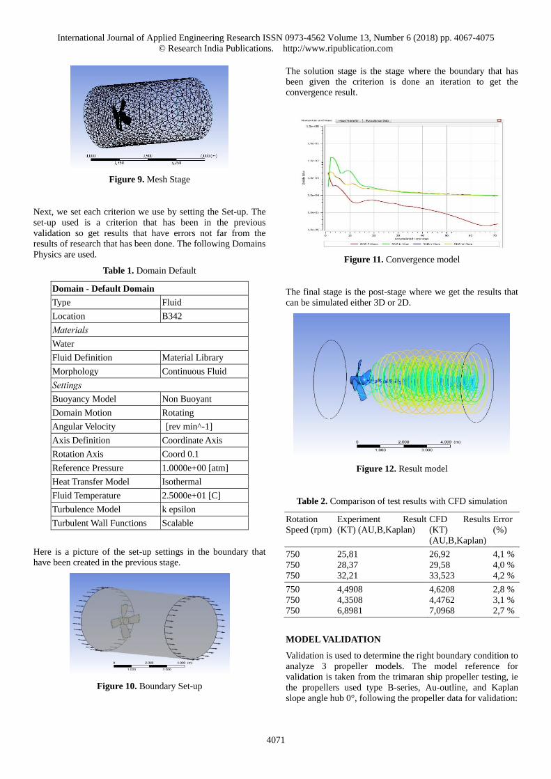
Pressure comparison on model
Here are the coordinates of each point and line used to
determine the pressure on the analysis.
Figure 14. Pressure Coordinates
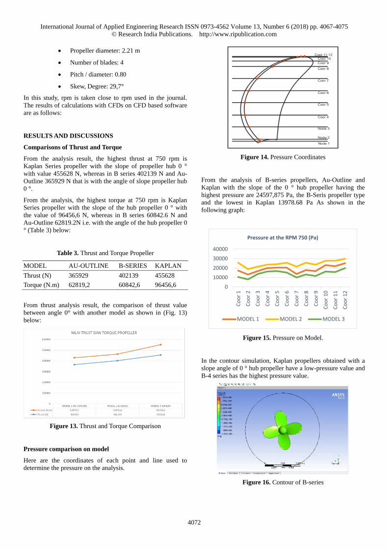
From the analysis of B-series propellers, Au-Outline and
Kaplan with the slope of the 0 ° hub propeller having the
highest pressure are 24597,875 Pa, the B-Seris propeller type
and the lowest in Kaplan 13978.68 Pa As shown in the
following graph:
Figure 15. Pressure on Model.
In the contour simulation, Kaplan propellers obtained with a
slope angle of 0 ° hub propeller have a low-pressure value and
B-4 series has the highest pressure value.
Figure 16. Contour of B-series
0
10000
20000
30000
40000
Co
or
1
Co
or
2
Co
or
3
Co
or
4
Co
or
5
Co
or
6
Co
or
7
Co
or
8
Co
or
9
Co
or
10
Co
or
11
Co
or
12
Pressure at the RPM 750 (Pa)
MODEL 1 MODEL 2 MODEL 3
International Journal of Applied Engineering Research ISSN 0973-4562 Volume 13, Number 6 (2018) pp. 4067-4075
© Research India Publications. http://www.ripublication.com
4073
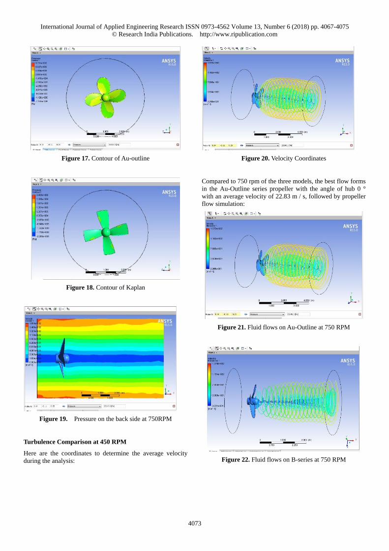
Figure 17. Contour of Au-outline
Figure 18. Contour of Kaplan
Figure 19. Pressure on the back side at 750RPM
Turbulence Comparison at 450 RPM
Here are the coordinates to determine the average velocity
during the analysis:
Figure 20. Velocity Coordinates
Compared to 750 rpm of the three models, the best flow forms
in the Au-Outline series propeller with the angle of hub 0 °
with an average velocity of 22.83 m / s, followed by propeller
flow simulation:
Figure 21. Fluid flows on Au-Outline at 750 RPM
Figure 22. Fluid flows on B-series at 750 RPM
International Journal of Applied Engineering Research ISSN 0973-4562 Volume 13, Number 6 (2018) pp. 4067-4075
© Research India Publications. http://www.ripublication.com
4074
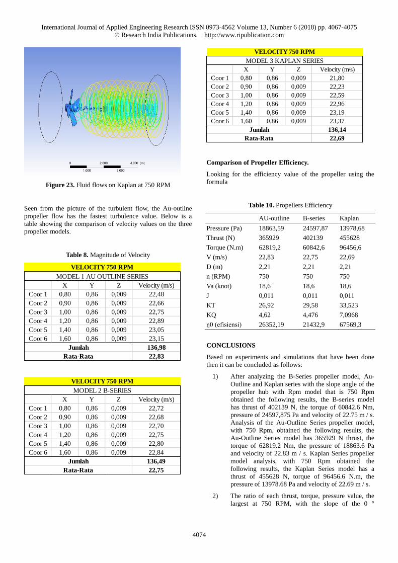
Figure 23. Fluid flows on Kaplan at 750 RPM
Seen from the picture of the turbulent flow, the Au-outline
propeller flow has the fastest turbulence value. Below is a
table showing the comparison of velocity values on the three
propeller models.
Table 8. Magnitude of Velocity
Comparison of Propeller Efficiency.
Looking for the efficiency value of the propeller using the
formula
Table 10. Propellers Efficiency
AU-outline B-series Kaplan
Pressure (Pa) 18863,59 24597,87 13978,68
Thrust (N) 365929 402139 455628
Torque (N.m) 62819,2 60842,6 96456,6
V (m/s) 22,83 22,75 22,69
D (m) 2,21 2,21 2,21
n (RPM) 750 750 750
Va (knot) 18,6 18,6 18,6
J 0,011 0,011 0,011
KT 26,92 29,58 33,523
KQ 4,62 4,476 7,0968
ŋ0 (efisiensi) 26352,19 21432,9 67569,3
CONCLUSIONS
Based on experiments and simulations that have been done
then it can be concluded as follows:
1) After analyzing the B-Series propeller model, Au-
Outline and Kaplan series with the slope angle of the
propeller hub with Rpm model that is 750 Rpm
obtained the following results, the B-series model
has thrust of 402139 N, the torque of 60842.6 Nm,
pressure of 24597,875 Pa and velocity of 22.75 m / s.
Analysis of the Au-Outline Series propeller model,
with 750 Rpm, obtained the following results, the
Au-Outline Series model has 365929 N thrust, the
torque of 62819.2 Nm, the pressure of 18863.6 Pa
and velocity of 22.83 m / s. Kaplan Series propeller
model analysis, with 750 Rpm obtained the
following results, the Kaplan Series model has a
thrust of 455628 N, torque of 96456.6 N.m, the
pressure of 13978.68 Pa and velocity of 22.69 m / s.
2) The ratio of each thrust, torque, pressure value, the
largest at 750 RPM, with the slope of the 0 °
X Y Z Velocity (m/s)
Coor 1 0,80 0,86 0,009 22,48
Coor 2 0,90 0,86 0,009 22,66
Coor 3 1,00 0,86 0,009 22,75
Coor 4 1,20 0,86 0,009 22,89
Coor 5 1,40 0,86 0,009 23,05
Coor 6 1,60 0,86 0,009 23,15
136,98
22,83
VELOCITY 750 RPM
Rata-Rata
MODEL 1 AU OUTLINE SERIES
Jumlah
X Y Z Velocity (m/s)
Coor 1 0,80 0,86 0,009 22,72
Coor 2 0,90 0,86 0,009 22,68
Coor 3 1,00 0,86 0,009 22,70
Coor 4 1,20 0,86 0,009 22,75
Coor 5 1,40 0,86 0,009 22,80
Coor 6 1,60 0,86 0,009 22,84
136,49
22,75
VELOCITY 750 RPM
Rata-Rata
MODEL 2 B-SERIES
Jumlah
X Y Z Velocity (m/s)
Coor 1 0,80 0,86 0,009 21,80
Coor 2 0,90 0,86 0,009 22,23
Coor 3 1,00 0,86 0,009 22,59
Coor 4 1,20 0,86 0,009 22,96
Coor 5 1,40 0,86 0,009 23,19
Coor 6 1,60 0,86 0,009 23,37
136,14
22,69
VELOCITY 750 RPM
Rata-Rata
MODEL 3 KAPLAN SERIES
Jumlah
International Journal of Applied Engineering Research ISSN 0973-4562 Volume 13, Number 6 (2018) pp. 4067-4075
© Research India Publications. http://www.ripublication.com
4075
propeller hub is the type of series Kaplan propeller.
This type of propeller Au-Outline is a type of
propeller that has the best turbulence speed and flow
at RPM 750 on a Trimaran ship.
3) The optimum propeller used on the KRI Klewang I
vessel is Propeller B-series with the angle of the hub
propeller 0 ° with 750 RPM with an efficiency value
of 0.01183.
ACKNOWLEDGEMENT
The works is funded by Research and Community Service
Institution Fund (DPA SUKPA LPPM-2017), Diponegoro
University on the project of “the Development of FRP Glass
Bottom Boat Trimaran Prototype to Support Underwater
Tourism in Karimunjawa Islands”, under the scheme of
applied and development research - (Riset Pengembangan dan
Penerapan) RPP program.
REFERENCES
[1] Anonymous, 1993,”The New Shorter Oxford English
Dictionary,” Clarendon Press, UK. Vol. 2.
[2] Joubert, P., 2004,”Some aspects of submarine design
part 1. Hydrodynamics,” Approved for Public
Release Distribution Unlimited (20041130), DSTO-
TR-1622. Fishermans Bend, VIC, Australia: DSTO
Platforms Sciences Laboratory, Commonwealth of
Australia.
[3] Andersen, P., Kappel, J.J., Spangenberg, E.,
2009,”Aspects of propeller developments for a
submarine,” First International Symposium on
Marine Propulsors, smp’09, Norway.
[4] Harvald, Sv, Aa, 1992, Resistance and Propulsion of
Ships, Wiley Interscience, USA.
[5] Carlton, J., 2007, Marine Propellers and Propulsion,
2nd Edition, Butterworth-Heinemann, USA.