f02 quarter-turn electric actuator - pow-mech.com€¦ · f02 quarter-turn electric actuator ......
TRANSCRIPT
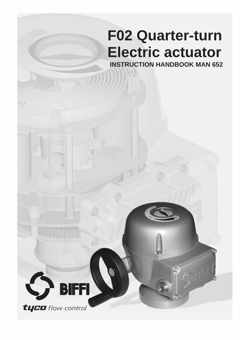
F02 Quarter-turnElectric actuator
INSTRUCTION HANDBOOK MAN 652
% &/((/
!@#$ flow control
Quarter-Turn Electric Actuator F02 Instruction manual
© Copyright by BIFFI ITALIA. All rights reserved. A !"£$ INTERNATIONAL LTD COMPANY
2
5 10/11/2007 Revised G. Riboli G. Alfieri 4 20/6/06 Revised A. Ghiadoni G. Alfieri 3 1/2/06 Revised A. Ghiadoni G. Alfieri 2 5/12/05 Revised A. Ghiadoni G. Alfieri 1 11/11/05 Revised A. Ghiadoni G. Alfieri 0 31/05/05 First Issue A. Ghiadoni G. Alfieri
Rev. Date Description Prepared Approved Note: BIFFI Italia has taken every care in collecting and verifying the documentation contained in the instruction and operating manual. The information herein contained is a reserved property of Biffi Italia.

Quarter-Turn Electric Actuator F02 Instruction manual
© Copyright by BIFFI ITALIA. All rights reserved. A !"£$ INTERNATIONAL LTD COMPANY
3
%&/((/ !"£$ flow control
F02 Quarter-turn Electric Actuators Instruction and operating manual
INDEX
1. GENERAL SAFETY INSTRUCTIONS..........................................4
2. MACHINE DESCRIPTION....................................................7
3. STORAGE AND PRE-INSTALLATION..............................11
4. INSTALLATION................................................................….13
5. LUBRICATION.......................................................................22
6. ACTUATOR SETTING AND CONFIGURATION...............22
7. MAINTENANCE AND TROUBLE-SHOOTING..................29
8. PARTS LISTS AND DRAWINGS..........................................33
Quarter-Turn Electric Actuator F02 Instruction manual
© Copyright by BIFFI ITALIA. All rights reserved. A !"£$ INTERNATIONAL LTD COMPANY
4
1. GENERAL SAFETY INSTRUCTIONS
1.1 Manufacturer
Manufacturer with respect to Machinery Directive 98/37 is Biffi Italia, as specified on the machinery label.
1.2 Intended Use
The F02 electric actuators covered in this Instruction and Operating Manual are designed for the operation of any kind of quarter-turn industrial valves (i.e., ball, butterfly, plug and control valves) used in a wide range of applications ranging from heavy industrial, chemical, petrochemical plants, waterworks, water pipelines, waste paper plants and power plants to food, brewing and heating, ventilation, air conditioning, etc. F02 actuators are produced by Biffi Italia and identified by a label with a product designation code. Biffi Italia will not be liable for any possible damage or physical injury resulting from use in other than the designated applications or by lack of care during installation, operation, adjustment and maintenance of the machine. Such risks lie entirely with the user. Depending on the specific working conditions, additional precautions may be requested. Considering that Biffi Italia has no direct control over particular applications, operation or maintenance conditions, it is the operator’s responsibility to comply with all applicable safety rules. Please inform Biffi Italia urgently if you face unsafe situations not described in this IOM. It is the sole responsibility of the operator to ensure that the local health and safety regulations are adhered to.
The noise emitted by F02 electric actuators during normal operation is less than 40 dB (A) with peak value equal to 85 dB (C). Standard references: ISO 11202 (1st edition, 1995-2-15).
Warning: It is assumed that the installation, setting, commissioning, maintenance and repair works are carried out by qualified personnel and checked by responsible Specialists.
Warning: Any repair work other than the operations outlines in this IOM will be strictly reserved to qualified BIFFI ITALIA personnel or to personnel directly authorised by the Company itself.
F02 electric actuators are designed in accordance with the applicable International Rules and Specifications, but the following Regulations must be observed in any case: • the general and safety regulations • the plant specific regulations and requirements • the proper use of personal and protective devices (glasses, clothing, gloves, etc) • the proper use of tools, lifting and transport equipment.
Warning: The electronic parts of the F02 and all the options can be damaged by a discharge of static electricity. Before you start, touch a grounded metal surface to discharge any static electricity.
Quarter-Turn Electric Actuator F02 Instruction manual
© Copyright by BIFFI ITALIA. All rights reserved. A !"£$ INTERNATIONAL LTD COMPANY
5
1.3 Terms and conditions
Biffi Italia guarantees each single product to be free from defects and to conform to current goods specifications. The warranty period is one year from the date of installation by the first user, or eighteen months from the date of shipment to the first user, whichever occurs first. No warranty is given for products which have been subject to improper storage, improper installation, misuse, or corrosion, or which have been modified or repaired by unauthorised personnel. Repair work due to improper use will be charged at standard rates.
1.4 Manufacturer’s Liability
Biffi Italia declines all liability in the event of: • use of the actuator in contravention of local safety at work legislation • incorrect installation, disregard or incorrect application of the instructions provided on the actuator
nameplate and in this manual • modifications without Biffi’s authorisation • work done on the unit by unqualified or unsuitable persons 1.5 Identification
1.5.1 WATER-, DUST-PROOF VERSION F02 actuators are designed and manufactured according to EN 60529 standards. Specific types of protection are printed on the label, as follows:
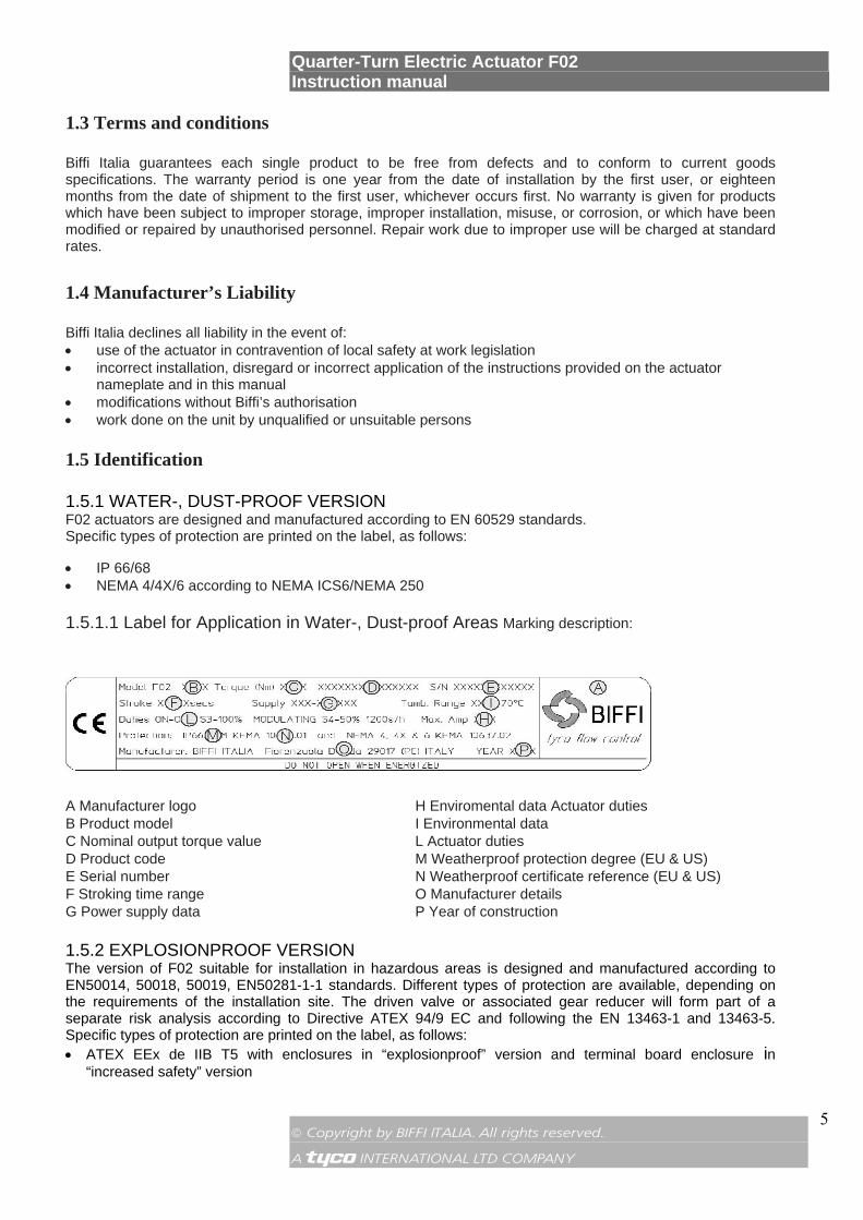
• IP 66/68 • NEMA 4/4X/6 according to NEMA ICS6/NEMA 250 1.5.1.1 Label for Application in Water-, Dust-proof Areas Marking description:
A Manufacturer logo H Enviromental data Actuator duties B Product model I Environmental data C Nominal output torque value L Actuator duties D Product code M Weatherproof protection degree (EU & US) E Serial number N Weatherproof certificate reference (EU & US) F Stroking time range O Manufacturer details G Power supply data P Year of construction 1.5.2 EXPLOSIONPROOF VERSION The version of F02 suitable for installation in hazardous areas is designed and manufactured according to EN50014, 50018, 50019, EN50281-1-1 standards. Different types of protection are available, depending on the requirements of the installation site. The driven valve or associated gear reducer will form part of a separate risk analysis according to Directive ATEX 94/9 EC and following the EN 13463-1 and 13463-5. Specific types of protection are printed on the label, as follows: • ATEX EEx de IIB T5 with enclosures in “explosionproof” version and terminal board enclosure in
“increased safety” version

Quarter-Turn Electric Actuator F02 Instruction manual
© Copyright by BIFFI ITALIA. All rights reserved. A !"£$ INTERNATIONAL LTD COMPANY
6
• NEC 500 (FM/CSA approvals) for Class 1 div. 1 groups C & D • NEMA 7 and NEMA 9 The above versions of F02 prevent the risk of explosion in the presence of gas or ignitable dusts. F02 actuators have IP 66/68 protection degree in accordance with EN60529.
Warning: Whenever F02 actuators must be installed in an HAZARDOUS AREA as defined by the applicable rules, it is mandatory to check whether the actuator nameplates indicate their suitability to an hazardous area, and the appropriate protection degree. Maintenance and repair works must be carried out by qualified personnel and checked by responsible specialists.
1.5.2.1 ATEX Label for Application in Hazardous Areas
A Manufacturer logo I Environmental data B Product model L Actuator duties C Nominal output torque value M Explosionproof protection degree D Product code N Weatherproof protection degree E Serial number O Atex certificate reference F Stroking time range P Manufacturer G Power supply data Q Year of construction H Enviromental data Actuator duties R Notified body for Atex quality assurance (Ineris) S Atex marking 1.6 Applicable Standards and Regulations
EN ISO 12100-1: Safety of machinery - Basic concepts, general principles for design. Part 1-Basic terminology, methodology. EN ISO 12100-1: Safety of machinery - Basic concepts, general principles for design. Part 2-Technical principles and specification. En 60204/1: Electrical equipment of industrial machines. Part 1- General requirements. EEC 98/37: Machinery directive. EEC 73/23: Low voltage directive. EEC 89/336: EMC Directive ATEX 94/9 EEC Directive
1.7 Extract from the Standard
Type of Hazard Zone Categories according to 94/9/CE Directive Gas, mists or vapours Zone 0 1G Gas, mists or vapours Zone 1 2G Gas, mists or vapours Zone 2 3G Dust Zone 20 1D Dust Zone 21 2D Dust Zone 22 3D

Quarter-Turn Electric Actuator F02 Instruction manual
© Copyright by BIFFI ITALIA. All rights reserved. A !"£$ INTERNATIONAL LTD COMPANY
7
2. MACHINE DESCRIPTION
2.1 General
The F02 is an electric quarter-turn actuator suitable to operate a valve in a 90° manoeuvre. The actuator introduces innovative solutions to provide maximum flexibility in terms of voltage supply, operation speed and torque options.
2.2 Principle of operation
The electric motor drives the input to an epicyclical gear train via a spur reduction. The input member of the epicyclical gear train carries a single compound planet gear which meshes with two internally toothed gears, one being the fixed annulus and the other being the output gear. The fixed annulus gear has external helical teeth meshing with a transversely fixed worm gear. Since the annulus cannot drive the worm gear this provides a fixing point for the annulus, and since the worm gear can drive the annulus, a means of manual operation is provided which needs no declutch. An end-of-travel-position detection device is operated via a position sensor directly linked to the output shaft. The valve position is continuously monitored in electric mode by means of a position sensor directly connected to the F02 output drive.
2.3 Electrical operation
-Control command “open”: counter-clockwise or clockwise rotation (selectable on the local panel) moves the valve to a completely or partially open position;
-Control command “closed”: clockwise or counter-clockwise rotation (selectable on the local panel) moves the valve to a completely or partially closed position;
Control system details are shown in the specific wiring diagram.
2.4 Manual operation
To be used in case of power supply failure or during actuator setting. The manual operating device is completely independent of the motor drive and can be operated at any time, whether or not the motor is running, without danger to the operator. The handwheel does not rotate during power operation. To close the valve turn the handwheel clockwise. To open the valve, turn the handwheel counter-clockwise. If the handwheel is turned during actuator electrical operation an error will occur and the actuator will stop.
Important: Handwheel rotation In standard applications clockwise rotation of the handwheel moves the valve to close position and counter-clockwise rotation moves the valve to open position. Different operation are clearly indicated on the handwheel.
Quarter-Turn Electric Actuator F02 Instruction manual
© Copyright by BIFFI ITALIA. All rights reserved. A !"£$ INTERNATIONAL LTD COMPANY
8
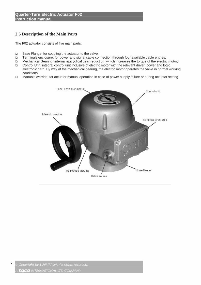
2.5 Description of the Main Parts
The F02 actuator consists of five main parts:
Base Flange: for coupling the actuator to the valve; Terminals enclosure: for power and signal cable connection through four available cable entries; Mechanical Gearing: internal epicyclical gear reduction, which increases the torque of the electric motor; Control Unit: integral control unit inclusive of electric motor with the relevant driver, power and logic
electronic card. By way of the mechanical gearing, the electric motor operates the valve in normal working conditions;
Manual Override: for actuator manual operation in case of power supply failure or during actuator setting.

Quarter-Turn Electric Actuator F02 Instruction manual
© Copyright by BIFFI ITALIA. All rights reserved. A !"£$ INTERNATIONAL LTD COMPANY
9
2.6 Optional modules
F02 actuators can be provided with several optional modules, as listed in the table below. Please refer to this table for possible combinations of available modules.
Optio
nal M
odul
e (1)
OM1
I/O ad
ditio
nal m
odul
e
OM2
Lith
ium
bat
tery
OM3
Loca
l inte
rface
Blue
toot
h co
mpo
nent
(2)
OM4
Blue
toot
h st
and-
alone
OM8
Asi 2
.-1
OM9
PDP
V0/V
1
OM10
FF
OM11
De
viceN
et
OM12
Lo
nWor
ks
OM13
3-
wire
s int
erfa
c
Code
(3)
X11X
12
OM1 • P1 OM1 • • P5 OM1 • • • P8 OM1 • • • • PC OM1 • • • P9 OM1 • • • PA OM1 • • P6 OM1 • • P7 OM2 • P2 OM3 • P3 OM3 • • PJ OM3 • • PD OM3 • • • PF OM4 • • P4 OM8 • 3A OM8 • • 4A OM8 • • 5A OM8 • • • 6A OM9 • 3P OM9 • • 4P OM9 • • 5P OM9 • • 6P OM10 3F OM10 • • 4F OM10 • • 5F OM10 • • • 6F OM11 • • 3D OM11 • • 4D OM11 • • 5D OM11 • • • 6D OM12 • 3L OM12 • • 4L OM12 • • 5L OM12 • • • 6L OM13 • PG OM13 • PH Notes: All modules except OM13 are available for both Universal Voltage and 3-Ph voltage versions. Bluetooth component is integrated in the OMx card: not available for integration by Local Organizations. • show the combination of modules specified in the Oracle code by digits X
11X
12.
Each Optional Module (OM) will be provided with its own Instruction and Operating Manual (MAN652_OM1
Quarter-Turn Electric Actuator F02 Instruction manual
© Copyright by BIFFI ITALIA. All rights reserved. A !"£$ INTERNATIONAL LTD COMPANY
10
through MAN652_OM13).
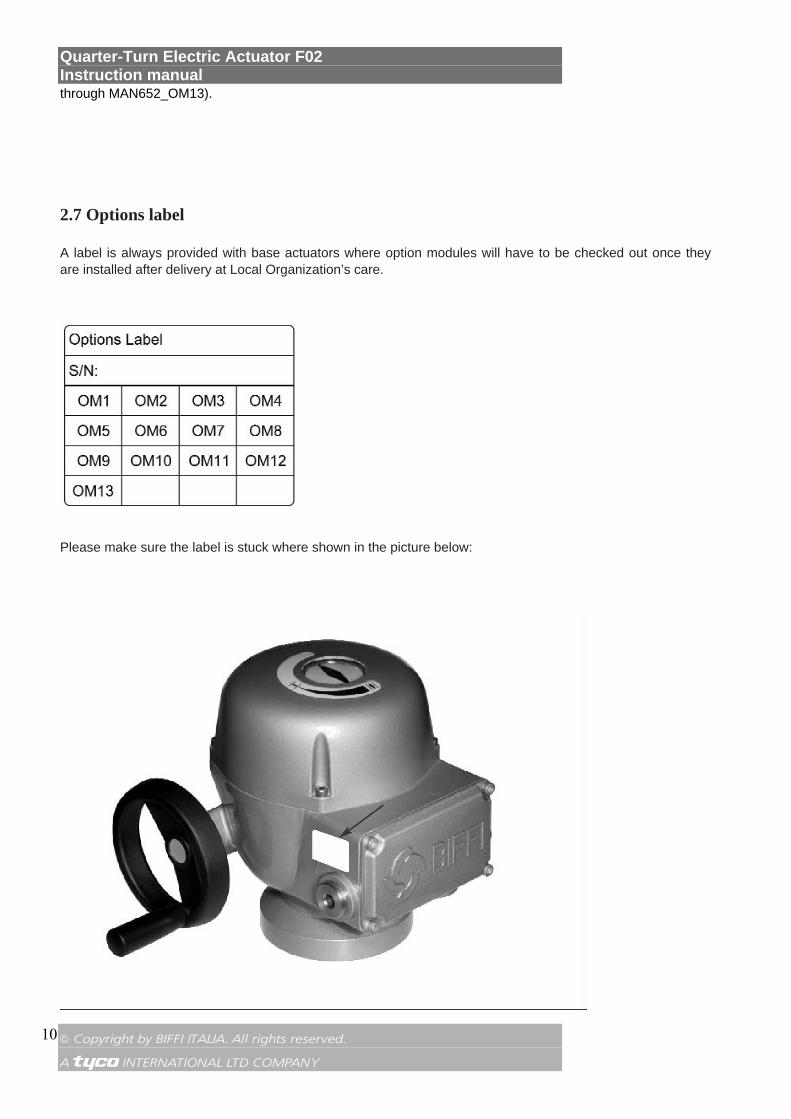
2.7 Options label
A label is always provided with base actuators where option modules will have to be checked out once they are installed after delivery at Local Organization’s care.
Please make sure the label is stuck where shown in the picture below:
Quarter-Turn Electric Actuator F02 Instruction manual
© Copyright by BIFFI ITALIA. All rights reserved. A !"£$ INTERNATIONAL LTD COMPANY
11
3. STORAGE AND PRE-INSTALLATION
Important: Not performing the following procedures will invalidate the product guarantee.
3.1 Checks to be carried out when the actuator is received
First of all check if the data on the nameplate (Model, Serial Number, Nominal Torque, Nominal Voltage range, Protection degree, Operating Speed range, Protection Class, etc.) correspond to the expected product data. If the actuator is received already assembled onto the valve, the setting of the mechanical stops and of the electric end-of-travel should have been already done during actuator assembly onto the valve. An additional check is anyway recommended to verify that all the requested settings have been completed as indicated in the present Instruction and Operating Manual. If the actuator is received separately from the valve, the setting of the mechanical stops and of the electric end-of-travel must be checked and, if necessary, carried out while assembling the actuator onto the valve. In any case, all the setting operations described in this Instruction and Operating Manual must be carried out. Check that the actuator was not damaged during transport: in particular, inspect the local position indicator area glass. If necessary, repair all damages to the paint-coat, etc. Check that the fitted accessories comply with those listed in the order acknowledgement and the delivery note. 3.2 Storage procedure
3.2.1 GENERAL The actuators leave the factory in perfect working conditions and with an excellent finish (these conditions are guaranteed by an individual inspection certificate); in order to maintain these characteristics until the actuator is installed on site, it is necessary to observe a few rules and take appropriate measures during the storage period. The base version of BIFFI actuators is weatherproof to IP 66/68. This condition can only be maintained if the units are correctly installed and connected on site, and if they were
previously correctly stored.
Warning: The standard plastic plugs used to close the cable entries are not weatherproof, they just prevent the entry of undesired objects during transport.
Important: The actuator handwheel is removed for transport. If the actuator must be shipped fully assembled, please make sure the handwheel is packed securely to avoid all possible damage.
3.2.2 STORAGE FOR A BRIEF PERIOD (LESS THAN ONE YEAR)
3.2.2.1 Indoor storage - Make sure the actuators are kept in a dry place, laid on a wooden pallet (not directly on the floor surface) and
protected from dust; - in very humid environments, a moisture absorbent desiccant packet should be introduced in the motor
enclosure. (Desiccant is not included in the actuator package).
3.2.2.2 Outdoor storage - Make sure the actuators are protected from the direct action of weather agents (protection by a canvas tarp
or similar); - place the actuators on a wooden pallet, or some raised platform, so that they are not in direct contact with the
ground, and protected from dust;

Quarter-Turn Electric Actuator F02 Instruction manual
© Copyright by BIFFI ITALIA. All rights reserved. A !"£$ INTERNATIONAL LTD COMPANY
12
- in very humid environments, a moisture absorbent desiccant packet should be introduced in the motor
enclosure. (Desiccant is not included in the actuator package); - if the actuators are supplied with standard plastic plugs, remove them from the cable entries and replace
them with weatherproof plugs.
3.2.3 LONG PERIOD STORAGE (MORE THAN ONE YEAR)
3.2.3.1 Indoor storage In addition to the instructions at point 3.2.2.1): - if the actuators are supplied with standard plastic plugs, replace them with weatherproof plugs; - the coupling parts (i.e. flange, etc.) must be coated with a protective oil or grease; (if possible, blank off the
flange by a protection disk); - in case the F02 is provided with an alkaline battery, remove it and store it in a dry and clean place.
3.2.3.2 Outdoor storage In addition to point 3.2.2.2): - if the actuators are supplied with standard plastic plugs, replace them with weatherproof (metal) plugs; - the coupling parts (i.e. flange, etc.) must be coated with a protective oil or grease; (if possible, blank off the
flange by a protection disk); - check the actuator general conditions, paying particular attention to the terminal board; - in case the F02 is provided with an alkaline battery, remove it and store it in a dry and clean place. 4. INSTALLATION
4.1 Checks to be performed before installation
To assemble the actuator onto the valve proceed as follows: • Check that the coupling dimensions of the valve flange and stem, or of the relevant extension, meet the
actuator coupling dimensions. • The electrical supply cables must be suitable for the power rating (see the test certificate delivered with
the actuator, if available, or the actuator nameplate); • Gather the necessary tools for the assembly and setting of the actuator controls; • Lubricate the valve stem with oil or grease to make the assembly easier: pay attention not to contaminate
with lubricant the flange surfaces which transmit the actuator torque. • Clean the valve flange and remove anything that might prevent a perfect adherence to the actuator flange
and especially all traces of grease. • Install the actuator onto the valve so that the shaft output drive enters the groove of the stem extension.
This coupling must take place without forcing and only with the weight of the actuator. When the actuator output shaft and the valve stem are connected, check the holes of the valve flange. If they do not meet with the holes of the spool piece flange or the stud bolts screwed into them, the actuator shaft output drive must be rotated. Actuate the manual override until coupling is made possible. Tighten the nuts of the connecting stud bolts evenly.
• If possible, operate the actuator to verify it moves the valve smoothly. If a long storage period has occurred, before reinstalling the actuator, please: • check the status of the O-ring seals; • check the installation of the plugs or cable glands on the cable entries; • check whether the enclosure covers or the actuator body are cracked or broken; • put the battery back into place. 4.2 Working condition
Standard F02 actuators are suitable for the following environment temperatures: -25°C to +70°C (-13°F to +158°F) with 80% humidity
Quarter-Turn Electric Actuator F02 Instruction manual
© Copyright by BIFFI ITALIA. All rights reserved. A !"£$ INTERNATIONAL LTD COMPANY
13
Special versions are available for extreme environment temperatures:
• -40°C to +70°C (-40°F to +158°F) with 80% humidity • -25°C to +70°C (-13°F to +158°F) with 100% humidity (tropicalization)
Special versions for hazardous areas: • -20°C to +65°C (-13°F to +149°F) with 80% humidity • -20°C to +65°C (-13°F to +149°F) with 100% humidity (tropicalization) • -40°C to +65°C (-40°F to +149°F) with 80% humidity
Important: Check the "ambient temperature range" embossed on the nameplate, for the correct utilisation with respect to the ambient temperature. Installation in ambient with temperature range outside the specified values will invalidate the warranty.
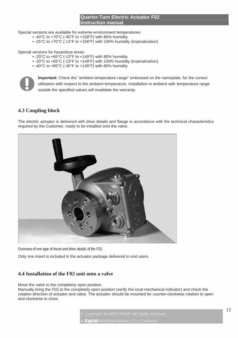
4.3 Coupling block
The electric actuator is delivered with drive details and flange in accordance with the technical characteristics required by the Customer, ready to be installed onto the valve.
Overview of one type of insert and drive details of the F02.
Only one insert is included in the actuator package delivered to end users.
4.4 Installation of the F02 unit onto a valve
Move the valve to the completely open position. Manually bring the F02 to the completely open position (verify the local mechanical indicator) and check the rotation direction of actuator and valve. The actuator should be mounted for counter-clockwise rotation to open and clockwise to close.
Quarter-Turn Electric Actuator F02 Instruction manual
© Copyright by BIFFI ITALIA. All rights reserved. A !"£$ INTERNATIONAL LTD COMPANY
14
Warning: Never lift the valve/actuator assembly without securing slings to both the valve and the actuator
Warning: Never use the handwheel to lift the actuator
The F02 unit can be installed onto the valve in two different ways:
Direct mounting: insert the valve shaft into the actuator bottom flange, taking care to correctly connect the insert. Fix the screws on the valve flange to the actuator coupling block.
Bracket mounting: install the bracket and the adapter onto the valve; then insert the valve shaft into the actuator bottom flange, taking care to correctly connect the insert. Fix the screws between the bracket and the valve flange and the actuator coupling block.
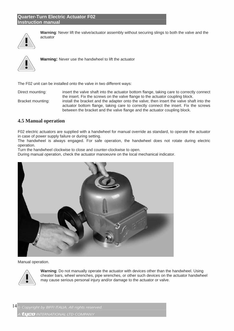
4.5 Manual operation
F02 electric actuators are supplied with a handwheel for manual override as standard, to operate the actuator in case of power supply failure or during setting. The handwheel is always engaged. For safe operation, the handwheel does not rotate during electric operation. Turn the handwheel clockwise to close and counter-clockwise to open. During manual operation, check the actuator manoeuvre on the local mechanical indicator.
Manual operation.
Warning: Do not manually operate the actuator with devices other than the handwheel. Using cheater bars, wheel wrenches, pipe wrenches, or other such devices on the actuator handwheel may cause serious personal injury and/or damage to the actuator or valve.
Quarter-Turn Electric Actuator F02 Instruction manual
© Copyright by BIFFI ITALIA. All rights reserved. A !"£$ INTERNATIONAL LTD COMPANY
15
Important: Handwheel rotation In standard applications clockwise rotation of the handwheel moves the valve to close position and counter-clockwise rotation moves the valve to open position. Different operation are clearly indicated on the handwheel.
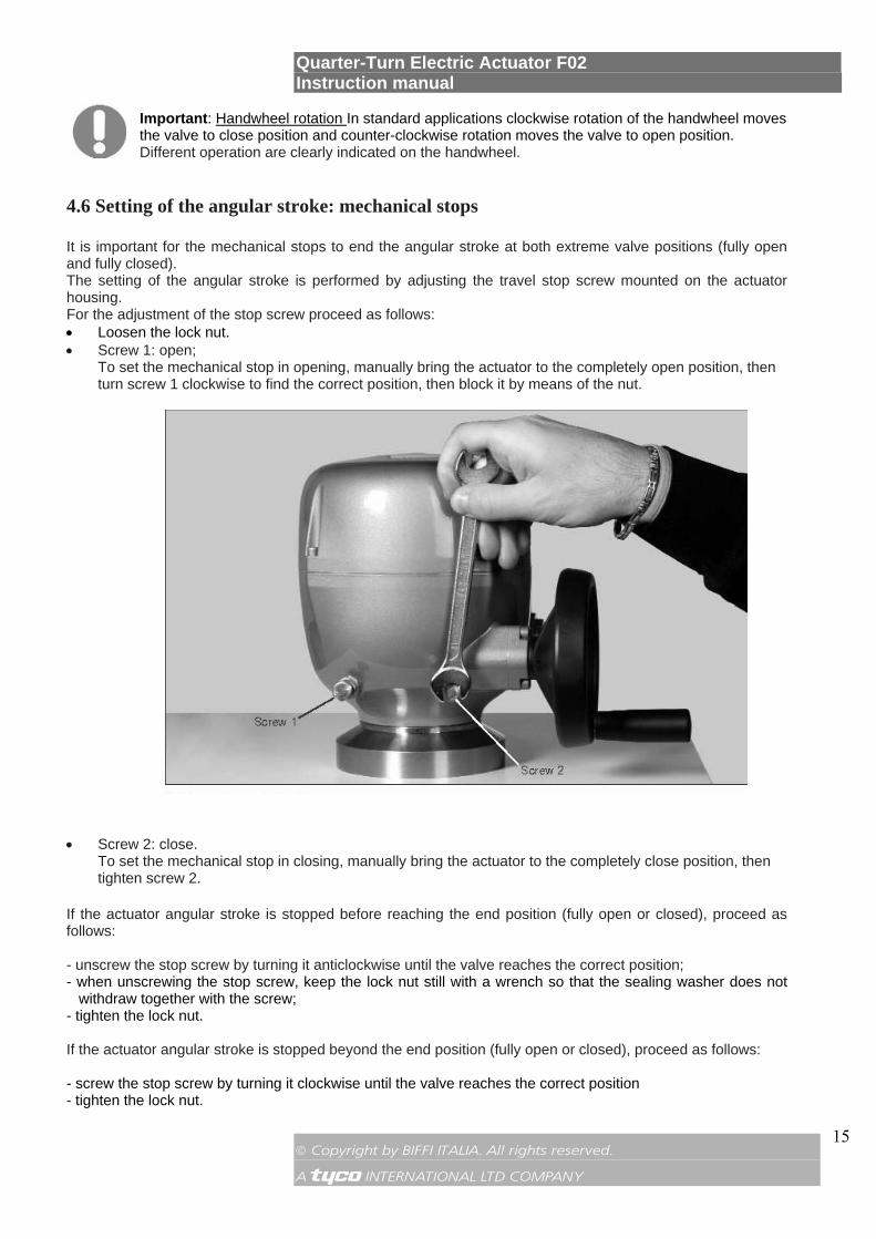
4.6 Setting of the angular stroke: mechanical stops
It is important for the mechanical stops to end the angular stroke at both extreme valve positions (fully open and fully closed). The setting of the angular stroke is performed by adjusting the travel stop screw mounted on the actuator housing. For the adjustment of the stop screw proceed as follows: • Loosen the lock nut. • Screw 1: open;
To set the mechanical stop in opening, manually bring the actuator to the completely open position, then turn screw 1 clockwise to find the correct position, then block it by means of the nut.
• Screw 2: close. To set the mechanical stop in closing, manually bring the actuator to the completely close position, then tighten screw 2.
If the actuator angular stroke is stopped before reaching the end position (fully open or closed), proceed as follows: - unscrew the stop screw by turning it anticlockwise until the valve reaches the correct position; - when unscrewing the stop screw, keep the lock nut still with a wrench so that the sealing washer does not
withdraw together with the screw; - tighten the lock nut. If the actuator angular stroke is stopped beyond the end position (fully open or closed), proceed as follows: - screw the stop screw by turning it clockwise until the valve reaches the correct position - tighten the lock nut.
Quarter-Turn Electric Actuator F02 Instruction manual
© Copyright by BIFFI ITALIA. All rights reserved. A !"£$ INTERNATIONAL LTD COMPANY
16
4.7 Electrical connections
Before powering the actuator, check that the supply voltage details on the nameplate are correct for the plant. Access to terminals for electrical connections is through the terminal cover.
Warning: After electrical on-field installation, please make sure all removal of the cover assembly is done in total observance of the applicable safety rules.
Warning: All the accessories (cable glands in particular) must be certified according to the requirements of the installation area and the relevant applicable regulations. Warning: Setting must be done while the actuator is powered on. As a consequence, all setting operations must be carried out by specifically qualified personnel for operations on powered electronic cards.
4.8 Plant requirements
Protection devices (over-current breakers, magneto-thermal switches or fuses) must be provided by the Customer to protect the main lines in case of motor over-current or loss of insulation between phases and earth.
Important: The following circuit breakers were identified on the basis of the actuator technical features:
• Reference: IEC EN 60947-2 • Characteristic: K
Since the features of the final destination plant are not available to Biffi, it is the Plant Designer’s or Installer’s responsibility to select the most appropriate electric protection.
Quarter-Turn Electric Actuator F02 Instruction manual
© Copyright by BIFFI ITALIA. All rights reserved. A !"£$ INTERNATIONAL LTD COMPANY
17
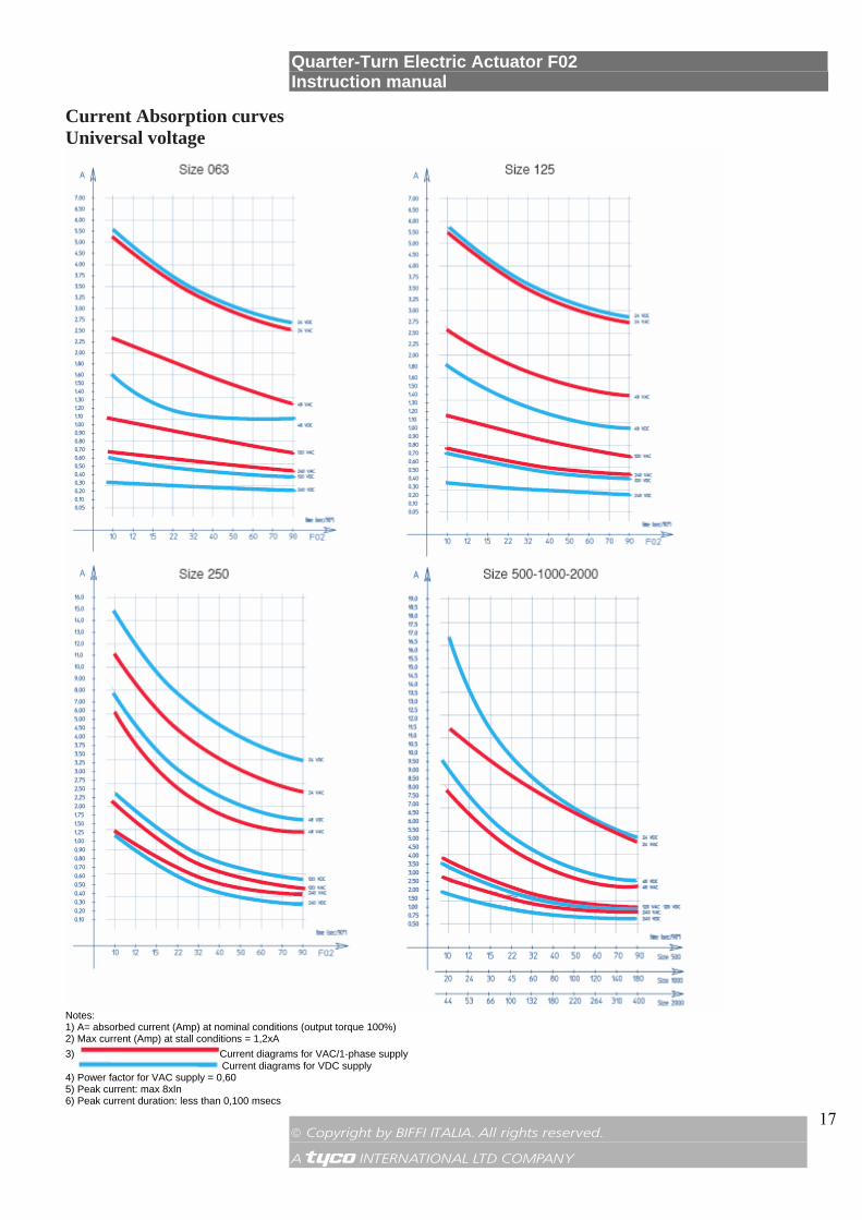
Current Absorption curves Universal voltage
Notes: 1) A= absorbed current (Amp) at nominal conditions (output torque 100%) 2) Max current (Amp) at stall conditions = 1,2xA 3) Current diagrams for VAC/1-phase supply Current diagrams for VDC supply 4) Power factor for VAC supply = 0,60 5) Peak current: max 8xIn 6) Peak current duration: less than 0,100 msecs

Quarter-Turn Electric Actuator F02 Instruction manual
© Copyright by BIFFI ITALIA. All rights reserved. A !"£$ INTERNATIONAL LTD COMPANY
18
Three-phase voltage
Notes: 1) 3-phases supply 50 or 60Hz 2) A = absorbed current (Amp) at nominal conditions with output torque set at 100% 3) Power factor = 1 approx. 4) Starting current peak less than 10 microsecs

Quarter-Turn Electric Actuator F02 Instruction manual
© Copyright by BIFFI ITALIA. All rights reserved. A !"£$ INTERNATIONAL LTD COMPANY
19
4.9 Removal of the terminal board enclosure
Using a 5 mm Allen key, loosen the four screws and remove the cover.
Warning: Pay attention not to damage the joint surfaces of the cover.
4.10 Cables connections
Before applying voltage to the F02 check that the electrical parameters (supply voltage and current) shown on the nameplate and on the attached wiring diagram are correct for the installation.
Important: All the accessories which equip the F02, in particular the cable glands, must be certified according to the Standard Directive and specific Rules applying to the products.
Overview of the electrical connections.

Quarter-Turn Electric Actuator F02 Instruction manual
© Copyright by BIFFI ITALIA. All rights reserved. A !"£$ INTERNATIONAL LTD COMPANY
20
Warning: Do not remove earth connection X while connecting the actuator to plant earthing.
Remove the plugs from the cable entries. For electrical connections use components (cable glands, cables, hoses, conduits) which meet the requirements and the applicable Codes of the plant specifications (mechanical protection and/or explosionproof protection). Screw the cable glands (or the conduits) tightly into the threaded entries, in order to guarantee the weatherproof and explosionproof protection (when applicable). Insert the connection cables into the electrical enclosures through the cable glands (or conduits) and, according to the Wiring Diagram in the main terminal board enclosure, connect the electrical supply, the control and the signal cables to the actuator, by linking them to the terminal blocks termination as per diagram. Replace the plastic plugs of the unused cable entries by metal ones, to guarantee perfect weatherproof tightness and to comply with the explosionproof protection codes (where applicable). Once the connections are completed, check that the controls and signals work properly. Two ground studs, one internal and one external, are provided to meet all local electric and safety regulations. Terminate the ground connections at least to the external stud marked GROUND. Connect the motor supply cable previously sized in accordance with: - the absorbed current correspondent to the actuator nominal torque with the torque limiting device set at 100 percent (see the test certificate attached to the actuator, if available, or the actuator nameplate); - the applicable plant and safety norms. Cable size 1 Power: 4 mm
2/ AWG 12 (max)
2 Controls: 1.5 mm2/ AWG 16 (max)
Quarter-Turn Electric Actuator F02 Instruction manual
© Copyright by BIFFI ITALIA. All rights reserved. A !"£$ INTERNATIONAL LTD COMPANY
21
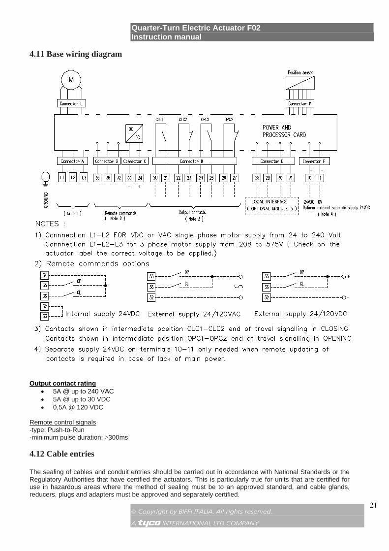
4.11 Base wiring diagram
Output contact rating • 5A @ up to 240 VAC • 5A @ up to 30 VDC • 0,5A @ 120 VDC
Remote control signals -type: Push-to-Run -minimum pulse duration: ≥300ms
4.12 Cable entries
The sealing of cables and conduit entries should be carried out in accordance with National Standards or the Regulatory Authorities that have certified the actuators. This is particularly true for units that are certified for use in hazardous areas where the method of sealing must be to an approved standard, and cable glands, reducers, plugs and adapters must be approved and separately certified.
Quarter-Turn Electric Actuator F02 Instruction manual
© Copyright by BIFFI ITALIA. All rights reserved. A !"£$ INTERNATIONAL LTD COMPANY
22
Important: • To prevent any water infiltration through the cable conduits, make sure the cable glands have the minimum protection degree required by the plant • If rigid conduits are used, we suggest placing a flexible pipe connection between the conduit and
the terminal board In order to properly connect the cables, remove the cable entry plugs and make all the necessary connections. To guarantee the proper weatherproof fit, IP 66/68 degree must be ensured: screw the cable glands tightly and block them with a thread sealant. The use of a thread sealant is necessary in case of explosionproof application.
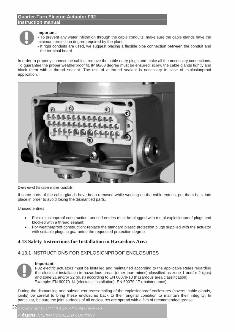
Overview of the cable entries conduits.
If some parts of the cable glands have been removed while working on the cable entries, put them back into place in order to avoid losing the dismantled parts. Unused entries:
• For explosionproof construction: unused entries must be plugged with metal explosionproof plugs and blocked with a thread sealant;
• For weatherproof construction: replace the standard plastic protection plugs supplied with the actuator with suitable plugs to guarantee the requested protection degree.
4.13 Safety Instructions for Installation in Hazardous Area
4.13.1 INSTRUCTIONS FOR EXPLOSIONPROOF ENCLOSURES
Important: F02 electric actuators must be installed and maintained according to the applicable Rules regarding the electrical installation in hazardous areas (other than mines) classified as zone 1 and/or 2 (gas) and zone 21 and/or 22 (dust) according to EN 60079-10 (hazardous area classification). Example: EN 60079-14 (electrical installation), EN 60079-17 (maintenance).
During the dismantling and subsequent reassembling of the explosionproof enclosures (covers, cable glands, joints) be careful to bring these enclosures back to their original condition to maintain their integrity. In particular, be sure the joint surfaces of all enclosures are spread with a film of recommended grease.

Quarter-Turn Electric Actuator F02 Instruction manual
© Copyright by BIFFI ITALIA. All rights reserved. A !"£$ INTERNATIONAL LTD COMPANY
23
Proceed as follows: • Do not damage the explosionproof mating surfaces on the housing and on the electrical enclosure
covers. • Reinstall all the screws that go with the dismantled parts, and block them with a thread sealant after
spreading them with a film of copper- or molybdenum-based grease. This will keep screws from sticking and make maintenance operations easier.
• Check that the bolts and screws are the same dimension and quality as the original ones (as stated on the nameplate), or a better quality.
• Replace the weatherproof seals that may have been removed (O-Ring for the covers).
Important: Each time the covers are opened or removed the condition of the seals must be checked. In case the seals are replaced, original spares must be supplied by Biffi.
Important: In case the screws of the cover must be replaced, SS Class A4 grade 80 screw must be used with minimum yield strength 600 N/mm
2
Warning: Do not electrically operate the F02 when the electrical enclosures are removed. Do not open the actuator covers when an explosive atmosphere may be present. Ignoring the above precautions could cause personal injury.
4.13.2 INSTALLATION IN ENVIRONMENT WITH EXPLOSIVE DUSTS
Important: F02 electric actuators must be installed and maintained according to the applicable Rules regarding the electrical installation in Hazardous areas (other than mines) classified as zone 21 and/or 22 (dust) according to EN 60079-10 (hazardous area classification). Example: installation and maintenance according to EN 50281-1-2.
Special attention is requested to the following:
• before the assembly the joint surfaces must be greased with silicone oil or equivalent. • cable glands must have minimum protection degree IP 66/68 (EN 60529). • periodically verify the quantity of dust deposited on the enclosure and clean it if more than 5mm. using
a damp cloth to avoid static electricity. 5. LUBRICATION
5.1 Lubrication inspection
The actuator is grease lubricated for life, therefore under normal working conditions no grease needs to be replaced or added. In case of maintenance the following grease is recommended: AEROSHELL GREASE 7 or equivalent, for ambient temperature -40 °C to 70 °C

Quarter-Turn Electric Actuator F02 Instruction manual
© Copyright by BIFFI ITALIA. All rights reserved. A !"£$ INTERNATIONAL LTD COMPANY
24
6. ACTUATOR SETTING AND CONFIGURATION
Before connecting power to the actuator, check that the voltages are correct and according to the indications on the nameplate. Wrong power supply could cause permanent damage to the electrical components. The setting of the F02 actuator can be carried out through the control panel inside the actuator control system. To access the panel, remove the actuator cover and when setting is complete replace the cover, following the procedures indicated below. 6.1 Removal of the control unit cover
Using a 5 mm Allen key, loosen the four screws and remove the cover.
Removal of the control unit cover.
Warning: Pay attention not to damage the joint surfaces of the cover Important: In case the cover screws must be replaced, SS Class A4 grade 80 screw must be used with minimum yield strength 600 N/mm
2
Once the setting is completed, reassemble the actuator cover.

Quarter-Turn Electric Actuator F02 Instruction manual
© Copyright by BIFFI ITALIA. All rights reserved. A !"£$ INTERNATIONAL LTD COMPANY
25
6.2 Local setting of the F02
Warning: Setting must be done while the actuator is powered on. As a consequence, all setting operations must be carried out by specifically qualified personnel for operations on powered electronic cards.
6.2.1 F02 DEFAULT GENERAL SETTING
Important: The actuators are set in the workshop with the following setting (Default Value): - CL limit switch by Position; - OP limit switch by Position; - Stroking time in CL (7): 15 secs for models 063/125/250/500, 30 secs for model 1.000 and 66 secs for model 2.000; - Stroking time in OP (7): 15 secs for models 063/125/250/500, 30 secs for model 1.000 and 66 secs for model 2.000; - Torque Limiting Device in CL set at about 100% of nominal torque; - Torque Limiting Device in OP set at about 100% of nominal torque; Reverse mode off.
If the application requires different actuator settings, please proceed as described in this chapter.
Important: Please note that the actuator setting does not need to be done in succession as indicated in the following pages. Each parameter can be set independently.
The setting of the actuator parameters is done through the following tools: - two rotary selector switches SW6 and SW4 for actuator setting; - Enter push-button SW5 (confirmation push-button); - dip-switch SW3 (enable setting function); - green LED indicating power On (switched on when power supply is available). - red LED for Enter confirmation (On once setting is confirmed); - mechanical stops.
F02 internal control panel and setting tools.
Quarter-Turn Electric Actuator F02 Instruction manual
© Copyright by BIFFI ITALIA. All rights reserved. A !"£$ INTERNATIONAL LTD COMPANY
26
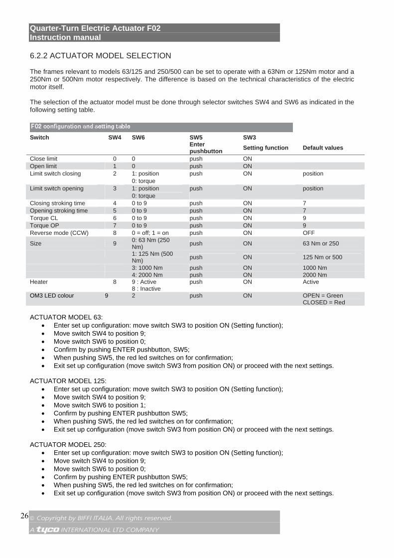
6.2.2 ACTUATOR MODEL SELECTION The frames relevant to models 63/125 and 250/500 can be set to operate with a 63Nm or 125Nm motor and a 250Nm or 500Nm motor respectively. The difference is based on the technical characteristics of the electric motor itself. The selection of the actuator model must be done through selector switches SW4 and SW6 as indicated in the following setting table.
Switch SW4 SW6 SW5 SW3 Enter
pushbutton Setting function Default values
Close limit 0 0 push ON Open limit 1 0 push ON Limit switch closing 2 1: position push ON position 0: torque Limit switch opening 3 1: position push ON position 0: torque Closing stroking time 4 0 to 9 push ON 7 Opening stroking time 5 0 to 9 push ON 7 Torque CL 6 0 to 9 push ON 9 Torque OP 7 0 to 9 push ON 9 Reverse mode (CCW) 8 0 = off; 1 = on push ON OFF
Size 9 0: 63 Nm (250 Nm) push ON 63 Nm or 250
1: 125 Nm (500 Nm) push ON 125 Nm or 500
3: 1000 Nm push ON 1000 Nm 4: 2000 Nm push ON 2000 Nm Heater 8 9 : Active
8 : Inactive push ON Active
OM3 LED colour 9 2 push ON OPEN = Green CLOSED = Red
ACTUATOR MODEL 63:
• Enter set up configuration: move switch SW3 to position ON (Setting function); • Move switch SW4 to position 9; • Move switch SW6 to position 0; • Confirm by pushing ENTER pushbutton, SW5; • When pushing SW5, the red led switches on for confirmation; • Exit set up configuration (move switch SW3 from position ON) or proceed with the next settings.
ACTUATOR MODEL 125:
• Enter set up configuration: move switch SW3 to position ON (Setting function); • Move switch SW4 to position 9; • Move switch SW6 to position 1; • Confirm by pushing ENTER pushbutton SW5; • When pushing SW5, the red led switches on for confirmation; • Exit set up configuration (move switch SW3 from position ON) or proceed with the next settings.
ACTUATOR MODEL 250:
• Enter set up configuration: move switch SW3 to position ON (Setting function); • Move switch SW4 to position 9; • Move switch SW6 to position 0; • Confirm by pushing ENTER pushbutton SW5; • When pushing SW5, the red led switches on for confirmation; • Exit set up configuration (move switch SW3 from position ON) or proceed with the next settings.
Quarter-Turn Electric Actuator F02 Instruction manual
© Copyright by BIFFI ITALIA. All rights reserved. A !"£$ INTERNATIONAL LTD COMPANY
27
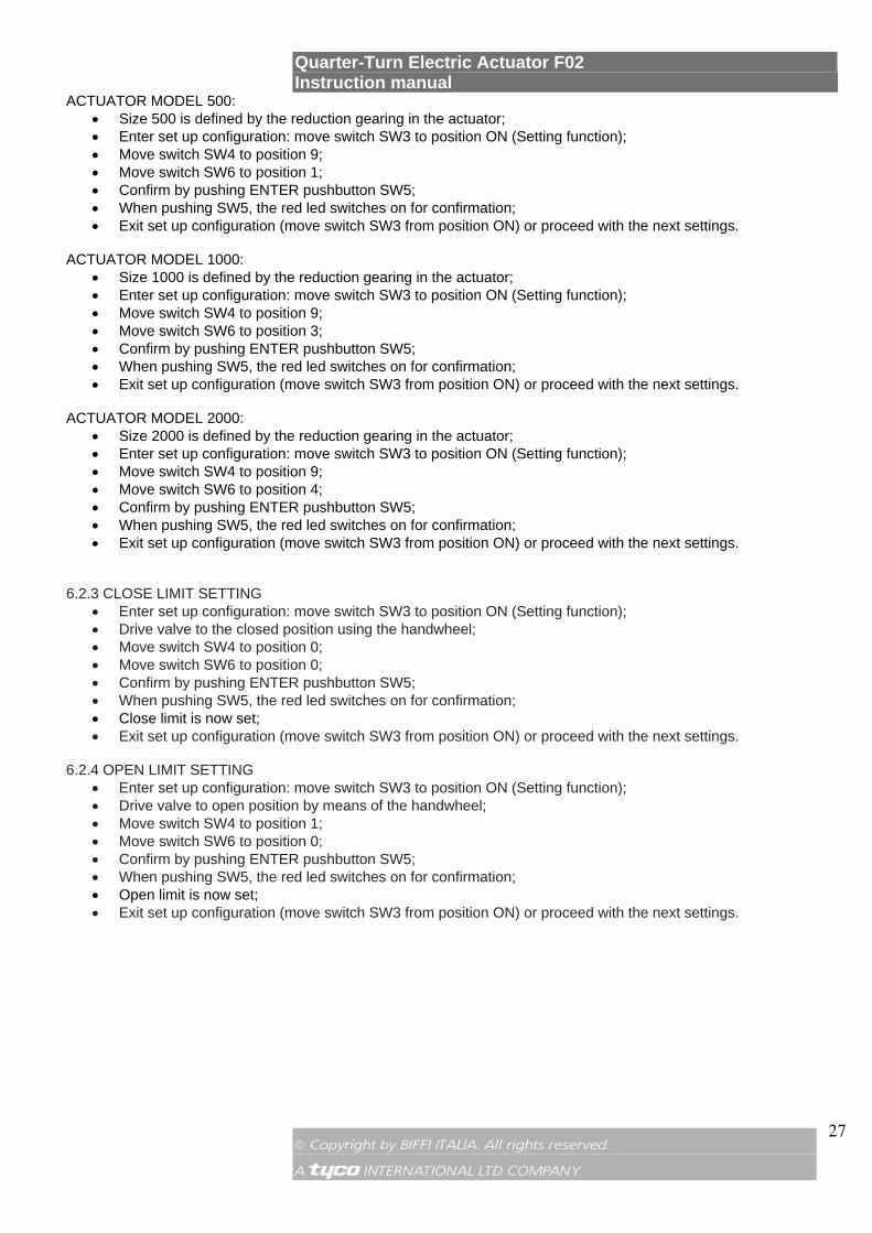
ACTUATOR MODEL 500: • Size 500 is defined by the reduction gearing in the actuator; • Enter set up configuration: move switch SW3 to position ON (Setting function); • Move switch SW4 to position 9; • Move switch SW6 to position 1; • Confirm by pushing ENTER pushbutton SW5; • When pushing SW5, the red led switches on for confirmation; • Exit set up configuration (move switch SW3 from position ON) or proceed with the next settings.
ACTUATOR MODEL 1000:
• Size 1000 is defined by the reduction gearing in the actuator; • Enter set up configuration: move switch SW3 to position ON (Setting function); • Move switch SW4 to position 9; • Move switch SW6 to position 3; • Confirm by pushing ENTER pushbutton SW5; • When pushing SW5, the red led switches on for confirmation; • Exit set up configuration (move switch SW3 from position ON) or proceed with the next settings.
ACTUATOR MODEL 2000:
• Size 2000 is defined by the reduction gearing in the actuator; • Enter set up configuration: move switch SW3 to position ON (Setting function); • Move switch SW4 to position 9; • Move switch SW6 to position 4; • Confirm by pushing ENTER pushbutton SW5; • When pushing SW5, the red led switches on for confirmation; • Exit set up configuration (move switch SW3 from position ON) or proceed with the next settings.
6.2.3 CLOSE LIMIT SETTING
• Enter set up configuration: move switch SW3 to position ON (Setting function); • Drive valve to the closed position using the handwheel; • Move switch SW4 to position 0; • Move switch SW6 to position 0; • Confirm by pushing ENTER pushbutton SW5; • When pushing SW5, the red led switches on for confirmation; • Close limit is now set; • Exit set up configuration (move switch SW3 from position ON) or proceed with the next settings.
6.2.4 OPEN LIMIT SETTING
• Enter set up configuration: move switch SW3 to position ON (Setting function); • Drive valve to open position by means of the handwheel; • Move switch SW4 to position 1; • Move switch SW6 to position 0; • Confirm by pushing ENTER pushbutton SW5; • When pushing SW5, the red led switches on for confirmation; • Open limit is now set; • Exit set up configuration (move switch SW3 from position ON) or proceed with the next settings.
Quarter-Turn Electric Actuator F02 Instruction manual
© Copyright by BIFFI ITALIA. All rights reserved. A !"£$ INTERNATIONAL LTD COMPANY
28
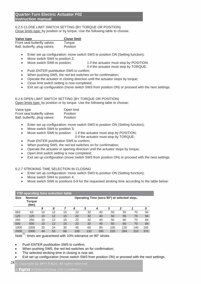
6.2.5 CLOSE LIMIT SWITCH SETTING (BY TORQUE OR POSITION) Close limits type: by position or by torque. Use the following table to choose: Valve type Close limit Front seal butterfly valves Torque Ball, butterfly, plug valves Position
• Enter set up configuration: move switch SW3 to position ON (Setting function); • Move switch SW4 to position 2; • Move switch SW6 to position: 1 if the actuator must stop by POSITION;
0 if the actuator must stop by TORQUE; • Push ENTER pushbutton SW5 to confirm; • When pushing SW5, the red led switches on for confirmation; • Operate the actuator in closing direction until the actuator stops by torque; • Close limit switch setting is now completed; • Exit set up configuration (move switch SW3 from position ON) or proceed with the next settings.
6.2.6 OPEN LIMIT SWITCH SETTING (BY TORQUE OR POSITION) Open limits type: by position or by torque. Use the following table to choose: Valve type Open limit Front seal butterfly valves Position Ball, butterfly, plug valves Position
• Enter set up configuration: move switch SW3 to position ON (Setting function); • Move switch SW4 to position 3; • Move switch SW6 to position: 1 if the actuator must stop by POSITION;
0 if the actuator must stop by TORQUE; • Push ENTER pushbutton SW5 to confirm; • When pushing SW5, the red led switches on for confirmation; • Operate the actuator in opening direction until the actuator stops by torque; • Open limit switch setting is now completed; • Exit set up configuration (move switch SW3 from position ON) or proceed with the next settings.
6.2.7 STROKING TIME SELECTION IN CLOSING
• Enter set up configuration: move switch SW3 to position ON (Setting function); • Move switch SW4 to position 4; • Move switch SW6 to positions 0-9 for the requested stroking time according to the table below:
Size Nominal
Torque (Nm)
Operating Time (secs 90°) at selected step(1)
9 8 7 6 5 4 3 2 1 0 063 63 10 12 15 22 32 40 50 55 70 94 125 125 10 12 15 22 32 40 50 55 70 94 250 250 10 12 15 22 32 40 50 60 70 84 500 500 10 12 15 22 32 40 50 60 70 84 1000 1000 20 24 30 45 60 80 100 120 140 165 2000 2000 44 53 66 100 132 180 220 264 310 370 Note
(1): times are guaranteed with 10% tolerance on 90° stroke.
• Push ENTER pushbutton SW5 to confirm; • When pushing SW5, the red led switches on for confirmation; • The selected stroking time in closing is now set. • Exit set up configuration (move switch SW3 from position ON) or proceed with the next settings.

Quarter-Turn Electric Actuator F02 Instruction manual
© Copyright by BIFFI ITALIA. All rights reserved. A !"£$ INTERNATIONAL LTD COMPANY
29
6.2.8 STROKING TIME SELECTION IN OPENING • Enter set up configuration: move switch SW3 to position ON (Setting function); • Move switch SW4 to position 5; • Move switch SW6 to positions 0-9 for the requested stroking time according to the table above; • Push ENTER pushbutton SW5 to confirm; • When pushing SW5, the red led switches on for confirmation; • The selected stroking time in opening is now set. • Exit configuration (move switch SW3 from position ON) or proceed with the next settings. 6.2.9 SETTING OF THE TORQUE LIMITING DEVICE IN CLOSING Closing torque limits: from 40% to 100% of the nominal torque. The nominal torque corresponding to 100% is set in-house and stated in the name plate. The limit torque value can be set in the closing direction by simply rotating rotary switch SW6 to the required position. The limit torque value can be set in a range between 40% and 100% of the nominal torque with steps of about 6%. Each step represents about 6,67% of the nominal torque value. • Enter set up configuration: move switch SW3 to position ON (Setting function); • Move switch SW4 to position 6; • Move switch SW6 to positions 0-9 for the requested Torque value (in percentage) in closing; • Push ENTER pushbutton SW5 to confirm; • When pushing SW5, the red led switches on for confirmation; • The setting of the torque limiting device in closing manoeuvre is now complete. • Exit set up configuration (move switch SW3 from position ON) or proceed with the next settings.
Warning: Torque switches setting must be done only with the authorization of the valve manufacturer, considering the specific valve figures.
6.2.10 SETTING OF THE TORQUE LIMITING DEVICE IN OPENING
Opening torque limits: from 40% to 100% of the nominal torque. The nominal torque corresponding to 100% is set in-house and stated in the name plate. The limit torque value can be set in the opening direction by simply rotating rotary switch SW6 to the required position. The limit torque value can be set in a range between 40% and 100% of the nominal torque with steps of about 6%. Each step represents about 6,67% of the nominal torque value. • Enter set up configuration: move switch SW3 to position ON (Setting function); • Move SW4 switch to position 7; • Move switch SW6 to positions 0-9 for the requested Torque value (in percentage) in opening; • Push ENTER pushbutton SW5 to confirm; • When pushing SW5, the red led switches on for confirmation; • The setting of the torque limiting device in opening is now complete. • Exit set up configuration (move switch SW3 from position ON) or proceed with the next settings.
Warning: Torque switches setting must be done only with the authorization of the valve manufacturer, considering the specific valve figures.
Quarter-Turn Electric Actuator F02 Instruction manual
© Copyright by BIFFI ITALIA. All rights reserved. A !"£$ INTERNATIONAL LTD COMPANY
30
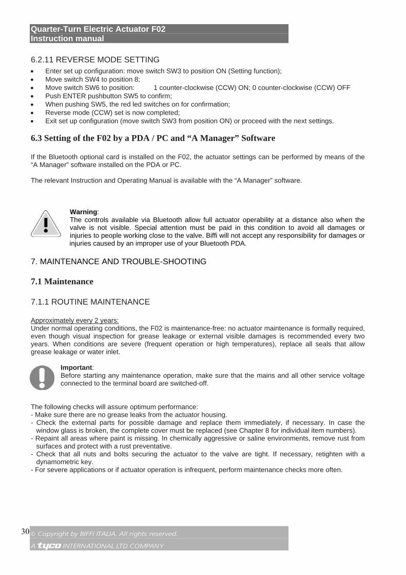
6.2.11 REVERSE MODE SETTING • Enter set up configuration: move switch SW3 to position ON (Setting function); • Move switch SW4 to position 8; • Move switch SW6 to position: 1 counter-clockwise (CCW) ON; 0 counter-clockwise (CCW) OFF • Push ENTER pushbutton SW5 to confirm; • When pushing SW5, the red led switches on for confirmation; • Reverse mode (CCW) set is now completed; • Exit set up configuration (move switch SW3 from position ON) or proceed with the next settings. 6.3 Setting of the F02 by a PDA / PC and “A Manager” Software
If the Bluetooth optional card is installed on the F02, the actuator settings can be performed by means of the “A Manager” software installed on the PDA or PC. The relevant Instruction and Operating Manual is available with the “A Manager” software.
Warning: The controls available via Bluetooth allow full actuator operability at a distance also when the valve is not visible. Special attention must be paid in this condition to avoid all damages or injuries to people working close to the valve. Biffi will not accept any responsibility for damages or injuries caused by an improper use of your Bluetooth PDA.
7. MAINTENANCE AND TROUBLE-SHOOTING
7.1 Maintenance
7.1.1 ROUTINE MAINTENANCE
Approximately every 2 years: Under normal operating conditions, the F02 is maintenance-free: no actuator maintenance is formally required, even though visual inspection for grease leakage or external visible damages is recommended every two years. When conditions are severe (frequent operation or high temperatures), replace all seals that allow grease leakage or water inlet.
Important: Before starting any maintenance operation, make sure that the mains and all other service voltage connected to the terminal board are switched-off.
The following checks will assure optimum performance: - Make sure there are no grease leaks from the actuator housing. - Check the external parts for possible damage and replace them immediately, if necessary. In case the
window glass is broken, the complete cover must be replaced (see Chapter 8 for individual item numbers). - Repaint all areas where paint is missing. In chemically aggressive or saline environments, remove rust from
surfaces and protect with a rust preventative. - Check that all nuts and bolts securing the actuator to the valve are tight. If necessary, retighten with a
dynamometric key. - For severe applications or if actuator operation is infrequent, perform maintenance checks more often.
Quarter-Turn Electric Actuator F02 Instruction manual
© Copyright by BIFFI ITALIA. All rights reserved. A !"£$ INTERNATIONAL LTD COMPANY
31
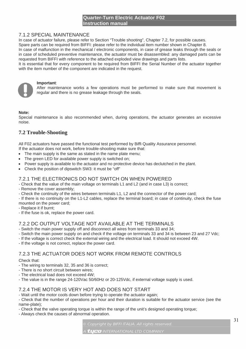
7.1.2 SPECIAL MAINTENANCE In case of actuator failure, please refer to Section “Trouble shooting”, Chapter 7.2, for possible causes. Spare parts can be required from BIFFI: please refer to the individual item number shown in Chapter 8. In case of malfunction in the mechanical / electronic components, in case of grease leaks through the seals or in case of scheduled preventive maintenance, the actuator must be disassembled: any damaged parts can be requested from BIFFI with reference to the attached exploded view drawings and parts lists. It is essential that for every component to be required from BIFFI the Serial Number of the actuator together with the item number of the component are indicated in the request.
Important: After maintenance works a few operations must be performed to make sure that movement is regular and there is no grease leakage through the seals.
Note: Special maintenance is also recommended when, during operations, the actuator generates an excessive noise.
7.2 Trouble-Shooting
All F02 actuators have passed the functional test performed by Biffi Quality Assurance personnel. If the actuator does not work, before trouble-shooting make sure that: • The main supply is the same as stated in the name plate menu; • The green LED for available power supply is switched on; • Power supply is available to the actuator and no protective device has declutched in the plant. • Check the position of dipswitch SW3: it must be “off” 7.2.1 THE ELECTRONICS DO NOT SWITCH ON WHEN POWERED - Check that the value of the main voltage on terminals L1 and L2 (and in case L3) is correct; - Remove the cover assembly; - Check the continuity of the wires between terminals L1, L2 and the connector of the power card; - If there is no continuity on the L1-L2 cables, replace the terminal board; in case of continuity, check the fuse mounted on the power card; - Replace it if burnt; - If the fuse is ok, replace the power card. 7.2.2 DC OUTPUT VOLTAGE NOT AVAILABLE AT THE TERMINALS - Switch the main power supply off and disconnect all wires from terminals 33 and 34; - Switch the main power supply on and check if the voltage on terminals 33 and 34 is between 23 and 27 Vdc; - If the voltage is correct check the external wiring and the electrical load. It should not exceed 4W. - If the voltage is not correct, replace the power card. 7.2.3 THE ACTUATOR DOES NOT WORK FROM REMOTE CONTROLS Check that: - The wiring to terminals 32, 35 and 36 is correct; - There is no short circuit between wires; - The electrical load does not exceed 4W; - The value is in the range 24-120Vac 50/60Hz or 20-125Vdc, if external voltage supply is used. 7.2.4 THE MOTOR IS VERY HOT AND DOES NOT START - Wait until the motor cools down before trying to operate the actuator again; - Check that the number of operations per hour and their duration is suitable for the actuator service (see the name-plate); - Check that the valve operating torque is within the range of the unit’s designed operating torque; - Always check the causes of abnormal operation.
Quarter-Turn Electric Actuator F02 Instruction manual
© Copyright by BIFFI ITALIA. All rights reserved. A !"£$ INTERNATIONAL LTD COMPANY
32
7.2.5 THE MOTOR RUNS BUT THE ACTUATOR DOES NOT MOVE THE VALVE - Verify that the drive insert correctly fits in the actuator base. - Verify that the drive insert has enough engagement with the valve stem. - Verify that the key correctly fits in bore/keyways applications. - Check that the valve works in manual operation. If not, it is necessary to check the manual control area as follows:
• Loosen the handwheel security dowel. • Remove the handwheel. • Check the integrity of the internal parts. • Proceeding with the assembly, follow the reverse order of the disassembly. • Make sure there are no foreign bodies. Pay attention not to damage the O-ring seals.
7.2.6 THE VALVE DOES NOT SEAT CORRECTLY - If the valve is stopped by torque in closing, increase the actuator output torque limit. - If the valve is stopped by position in closing, check that the valve reaches its seat position, then readjust the setting of the position limit. - The internal trim of the valve may be damaged. 7.2.7 EXCESSIVE TORQUE FOR VALVE OPERATION - Clean, lubricate and check the valve stem. - Valve packing too tight: loosen the gland bolt nuts. - Check that the internal valve trim or the reducer gears are well lubricated and not damaged. 7.2.8 THE ACTUATOR DOES NOT STOP IN FULLY OPEN OR FULLY CLOSED
POSITION - Check that the actual open and close positions of the valve respectively correspond to 100% and 0%. - Make sure that the torque and travel limits are correctly set (see Chapter 6).
Quarter-Turn Electric Actuator F02 Instruction manual
© Copyright by BIFFI ITALIA. All rights reserved. A !"£$ INTERNATIONAL LTD COMPANY
33
8. PARTS LISTS AND DRAWINGS
This section includes the drawings and parts lists of each component and subassembly of F02 actuators.
Important: When ordering spare parts, please indicate the serial number embossed on the actuator nameplate.
Important: When ordering spare parts, please refer to the marked part list items on the attached drawings.
Important: Recommended spares for routine maintenance are marked with this sign • on parts list.
Quarter-Turn Electric Actuator F02 Instruction manual
© Copyright by BIFFI ITALIA. All rights reserved. A !"£$ INTERNATIONAL LTD COMPANY
34
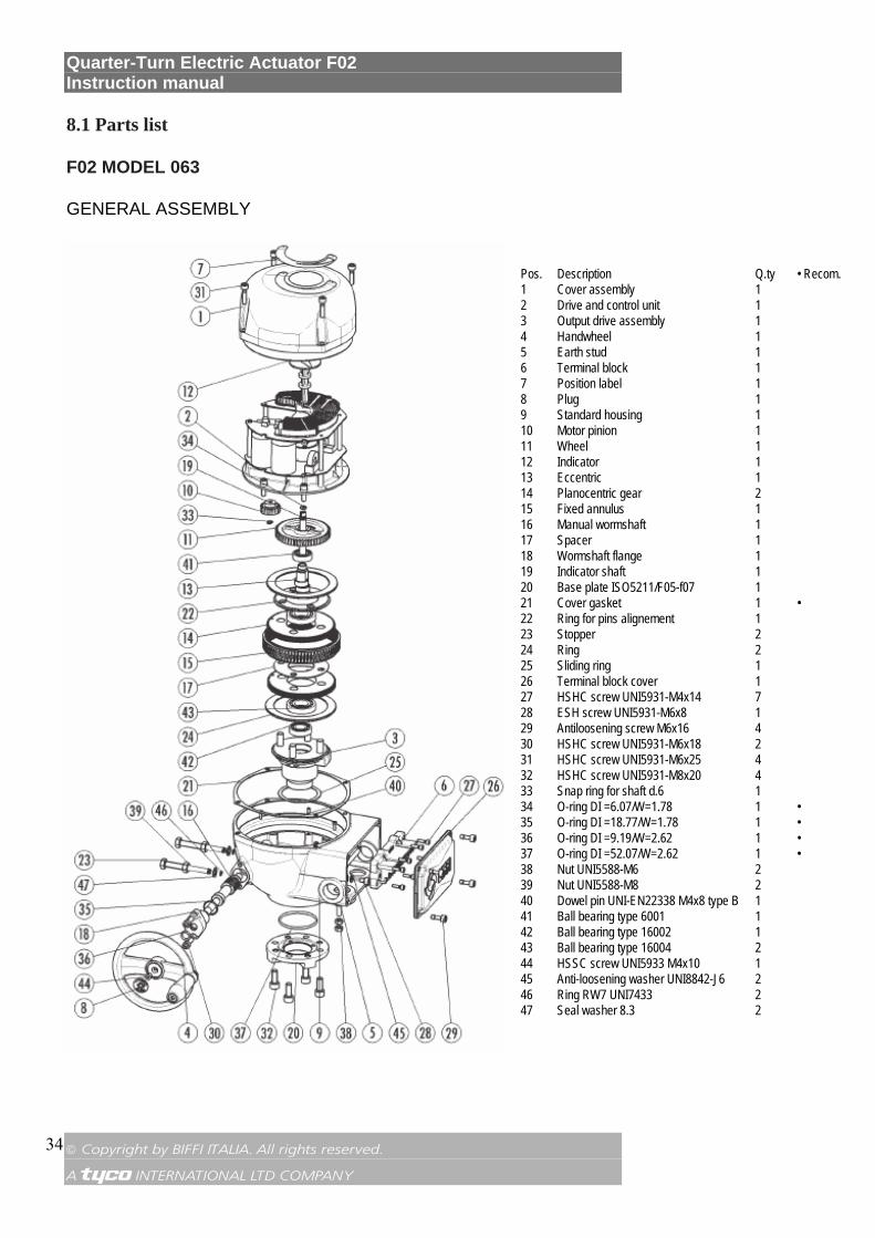
8.1 Parts list
F02 MODEL 063
GENERAL ASSEMBLY
Pos. Description Q.ty • Recom. 1 Cover assembly 1 2 Drive and control unit 1 3 Output drive assembly 1 4 Handwheel 1 5 Earth stud 1 6 Terminal block 1 7 Position label 1 8 Plug 1 9 Standard housing 1 10 Motor pinion 1 11 Wheel 1 12 Indicator 1 13 Eccentric 1 14 Planocentric gear 2 15 Fixed annulus 1 16 Manual wormshaft 1 17 Spacer 1 18 Wormshaft flange 1 19 Indicator shaft 1 20 Base plate ISO5211/F05-f07 1 21 Cover gasket 1 • 22 Ring for pins alignement 1 23 Stopper 2 24 Ring 2 25 Sliding ring 1 26 Terminal block cover 1 27 HSHC screw UNI5931-M4x14 7 28 ESH screw UNI5931-M6x8 1 29 Antiloosening screw M6x16 4 30 HSHC screw UNI5931-M6x18 2 31 HSHC screw UNI5931-M6x25 4 32 HSHC screw UNI5931-M8x20 4 33 Snap ring for shaft d.6 1 34 O-ring DI =6.07/W=1.78 1 • 35 O-ring DI =18.77/W=1.78 1 • 36 O-ring DI =9.19/W=2.62 1 • 37 O-ring DI =52.07/W=2.62 1 • 38 Nut UNI5588-M6 2 39 Nut UNI5588-M8 2 40 Dowel pin UNI-EN22338 M4x8 type B 1 41 Ball bearing type 6001 1 42 Ball bearing type 16002 1 43 Ball bearing type 16004 2 44 HSSC screw UNI5933 M4x10 1 45 Anti-loosening washer UNI8842-J6 2 46 Ring RW7 UNI7433 2 47 Seal washer 8.3 2
Quarter-Turn Electric Actuator F02 Instruction manual
© Copyright by BIFFI ITALIA. All rights reserved. A !"£$ INTERNATIONAL LTD COMPANY
35
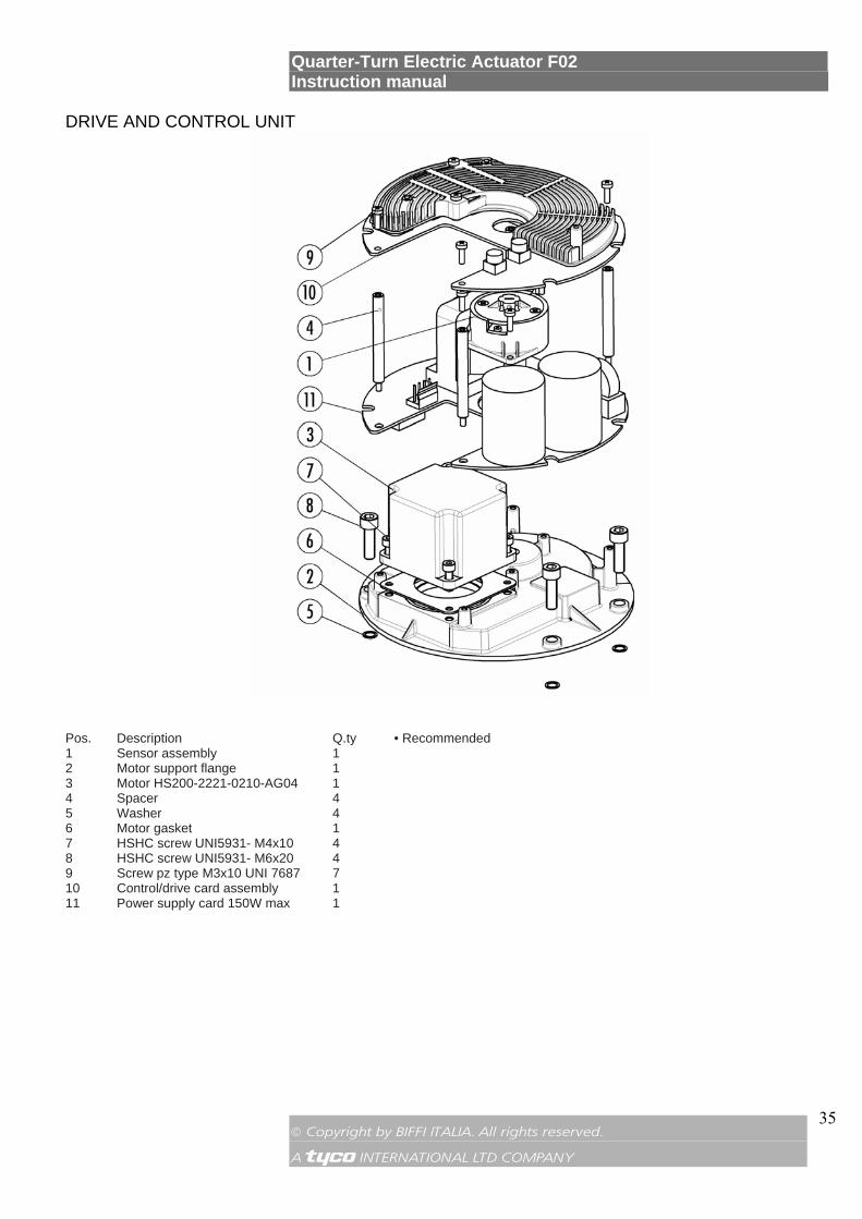
DRIVE AND CONTROL UNIT
Pos. Description Q.ty • Recommended 1 Sensor assembly 1 2 Motor support flange 1 3 Motor HS200-2221-0210-AG04 1 4 Spacer 4 5 Washer 4 6 Motor gasket 1 7 HSHC screw UNI5931- M4x10 4 8 HSHC screw UNI5931- M6x20 4 9 Screw pz type M3x10 UNI 7687 7 10 Control/drive card assembly 1 11 Power supply card 150W max 1
Quarter-Turn Electric Actuator F02 Instruction manual
© Copyright by BIFFI ITALIA. All rights reserved. A !"£$ INTERNATIONAL LTD COMPANY
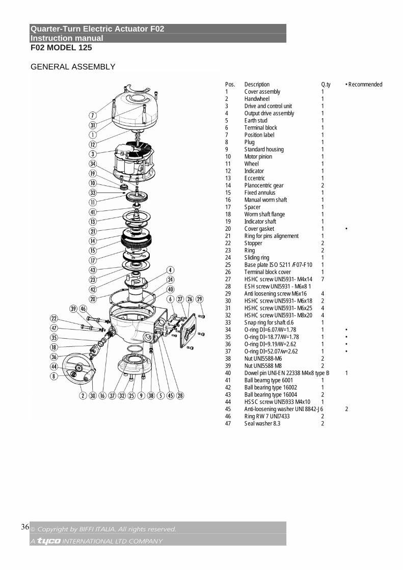
36
F02 MODEL 125
GENERAL ASSEMBLY Pos. Description Q.ty • Recommended 1 Cover assembly 1 2 Handwheel 1 3 Drive and control unit 1 4 Output drive assembly 1 5 Earth stud 1 6 Terminal block 1 7 Position label 1 8 Plug 1 9 Standard housing 1 10 Motor pinion 1 11 Wheel 1 12 Indicator 1 13 Eccentric 1 14 Planocentric gear 2 15 Fixed annulus 1 16 Manual worm shaft 1 17 Spacer 1 18 Worm shaft flange 1 19 Indicator shaft 1 20 Cover gasket 1 • 21 Ring for pins alignement 1 22 Stopper 2 23 Ring 2 24 Sliding ring 1 25 Base plate ISO 5211 /F07-F10 1 26 Terminal block cover 1 27 HSHC screw UNI5931- M4x14 7 28 ESH screw UNI5931 - M6x8 1 29 Anti loosening screw M6x16 4 30 HSHC screw UNI5931- M6x18 2 31 HSHC screw UNI5931- M6x25 4 32 HSHC screw UNI5931- M8x20 4 33 Snap ring for shaft d.6 1 34 O-ring DI=6.07/W=1.78 1 • 35 O-ring DI=18.77/W=1.78 1 • 36 O-ring DI=9.19/W=2.62 1 • 37 O-ring DI=52.07/w=2.62 1 • 38 Nut UNI5588-M6 2 39 Nut UNI5588 M8 2 40 Dowel pin UNI-EN 22338 M4x8 type B 1 41 Ball bearng type 6001 1 42 Ball bearing type 16002 1 43 Ball bearing type 16004 2 44 HSSC screw UNI5933 M4x10 1 45 Anti-loosening washer UNI 8842-J6 2 46 Ring RW 7 UNI7433 2 47 Seal washer 8.3 2

Quarter-Turn Electric Actuator F02 Instruction manual
© Copyright by BIFFI ITALIA. All rights reserved. A !"£$ INTERNATIONAL LTD COMPANY
37
DRIVE AND CONTROL UNIT
Pos. Description Q.ty • Recommended 1 Sensor assembly 1 2 Motor support flange 1 3 Spacer 4 4 Washer 4 5 Motor gasket 1 6 Motor HS200-2231-0300-AH0 4 1 7 HSHC screw UNI5931- M4x10 4 8 HSHC screw UNI5931- M6x20 4 9 Screw pz type M3x10 UNI 7687 7 10 Control/drive card assembly 1 11 Power supply card 150w max 1
Quarter-Turn Electric Actuator F02 Instruction manual
© Copyright by BIFFI ITALIA. All rights reserved. A !"£$ INTERNATIONAL LTD COMPANY
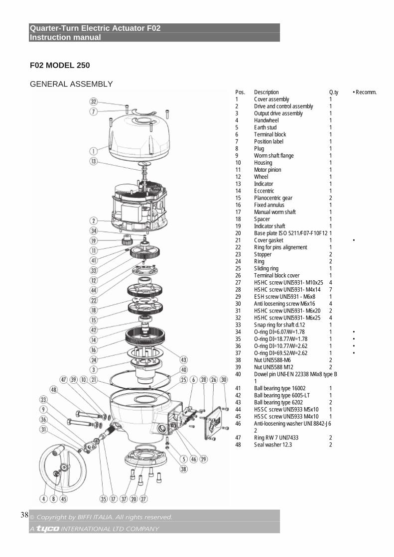
38
F02 MODEL 250
GENERAL ASSEMBLY Pos. Description Q.ty • Recomm. 1 Cover assembly 1 2 Drive and control assembly 1 3 Output drive assembly 1 4 Handwheel 1 5 Earth stud 1 6 Terminal block 1 7 Position label 1 8 Plug 1 9 Worm shaft flange 1 10 Housing 1 11 Motor pinion 1 12 Wheel 1 13 Indicator 1 14 Eccentric 1 15 Planocentric gear 2 16 Fixed annulus 1 17 Manual worm shaft 1 18 Spacer 1 19 Indicator shaft 1 20 Base plate ISO 5211/F07-F10F12 1 21 Cover gasket 1 • 22 Ring for pins alignement 1 23 Stopper 2 24 Ring 2 25 Sliding ring 1 26 Terminal block cover 1 27 HSHC screw UNI5931- M10x25 4 28 HSHC screw UNI5931- M4x14 7 29 ESH screw UNI5931 - M6x8 1 30 Anti loosening screw M6x16 4 31 HSHC screw UNI5931- M6x20 2 32 HSHC screw UNI5931- M6x25 4 33 Snap ring for shaft d.12 1 34 O-ring DI=6.07/W=1.78 1 • 35 O-ring DI=18.77/W=1.78 1 • 36 O-ring DI=10.77/W=2.62 1 • 37 O-ring DI=69.52/W=2.62 1 • 38 Nut UNI5588-M6 2 39 Nut UNI5588 M12 2 40 Dowel pin UNI-EN 22338 M4x8 type B 1 41 Ball bearing type 16002 1 42 Ball bearing type 6005-LT 1 43 Ball bearing type 6202 2 44 HSSC screw UNI5933 M5x10 1 45 HSSC screw UNI5933 M4x10 1 46 Anti-loosening washer UNI 8842-J6 2 47 Ring RW 7 UNI7433 2 48 Seal washer 12.3 2
Quarter-Turn Electric Actuator F02 Instruction manual
© Copyright by BIFFI ITALIA. All rights reserved. A !"£$ INTERNATIONAL LTD COMPANY
39
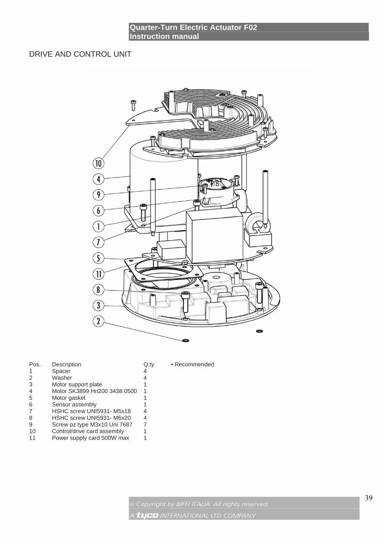
DRIVE AND CONTROL UNIT
Pos. Description Q.ty • Recommended 1 Spacer 4 2 Washer 4 3 Motor support plate 1 4 Motor SK3899 Hn200 3438 0500 1 5 Motor gasket 1 6 Sensor assembly 1 7 HSHC screw UNI5931- M5x18 4 8 HSHC screw UNI5931- M6x20 4 9 Screw pz type M3x10 Uni 7687 7 10 Control/drive card assembly 1 11 Power supply card 500W max 1
Quarter-Turn Electric Actuator F02 Instruction manual
© Copyright by BIFFI ITALIA. All rights reserved. A !"£$ INTERNATIONAL LTD COMPANY
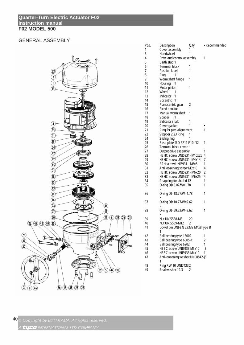
40
F02 MODEL 500
GENERAL ASSEMBLY Pos. Description Q.ty • Recommended 1 Cover assembly 1 3 Handwheel 1 4 Drive and control assembly 1 5 Earth stud 1 6 Terminal block 1 7 Position label 1 8 Plug 1 9 Worm shaft flange 1 10 Housing 1 11 Motor pinion 1 12 Wheel 1 13 Indicator 1 14 Eccentric 1 15 Planocentric gear 2 16 Fixed annulus 1 17 Manual worm shaft 1 18 Spacer 1 19 Indicator shaft 1 20 Cover gasket 1 • 21 Ring for pins alignement 1 22 Stopper 2 23 Ring 1 24 Sliding ring 1 25 Base plate ISO 5211 F10-f12 1 26 Terminal block cover 1 27 Output drive assembly 1 28 HSHC screw UNI5931- M10x25 4 29 HSHC screw UNI5931- M4x14 7 30 ESH screw UNI5931 - M6x8 1 31 Anti loosening screw M6x16 4 32 HSHC screw UNI5931- M6x20 2 33 HSHC screw UNI5931- M6x25 4 34 Snap ring for shaft d.12 1 35 O-ring DI=6.07/W=1.78 1 • 36 O-ring DI=18.77/W=1.78 1 • 37 O-ring DI=10.77/W=2.62 1 • 38 O-ring DI=69.52/W=2.62 1 • 39 Nut UNI5588-M6 20 40 Nut UNI5589-M12 2 41 Dowel pin UNI-EN 22338 M4x8 type B 1 42 Ball bearing type 16002 1 43 Ball bearing type 6005-lt 2 44 Ball bearing type 6202 1 45 HSSC screw UNI5933 M5x10 3 46 HSSC screw UNI5933 M4x10 1 47 Anti-loosening washer UNI 8842-j6 1 48 Ring RW 10 UNI7433 2 49 Seal washer 12.3 2
Quarter-Turn Electric Actuator F02 Instruction manual
© Copyright by BIFFI ITALIA. All rights reserved. A !"£$ INTERNATIONAL LTD COMPANY
41
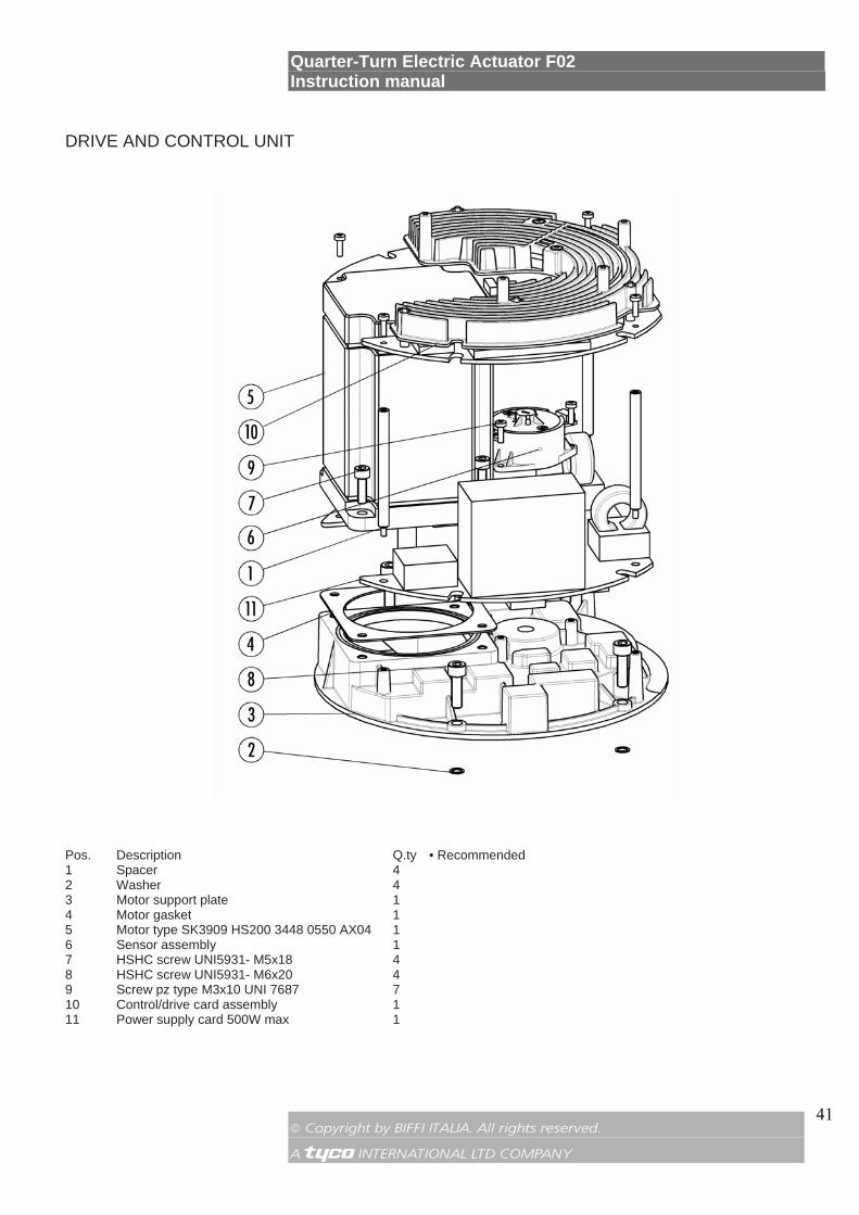
DRIVE AND CONTROL UNIT
Pos. Description Q.ty • Recommended 1 Spacer 4 2 Washer 4 3 Motor support plate 1 4 Motor gasket 1 5 Motor type SK3909 HS200 3448 0550 AX04 1 6 Sensor assembly 1 7 HSHC screw UNI5931- M5x18 4 8 HSHC screw UNI5931- M6x20 4 9 Screw pz type M3x10 UNI 7687 7 10 Control/drive card assembly 1 11 Power supply card 500W max 1
Quarter-Turn Electric Actuator F02 Instruction manual
© Copyright by BIFFI ITALIA. All rights reserved. A !"£$ INTERNATIONAL LTD COMPANY
42
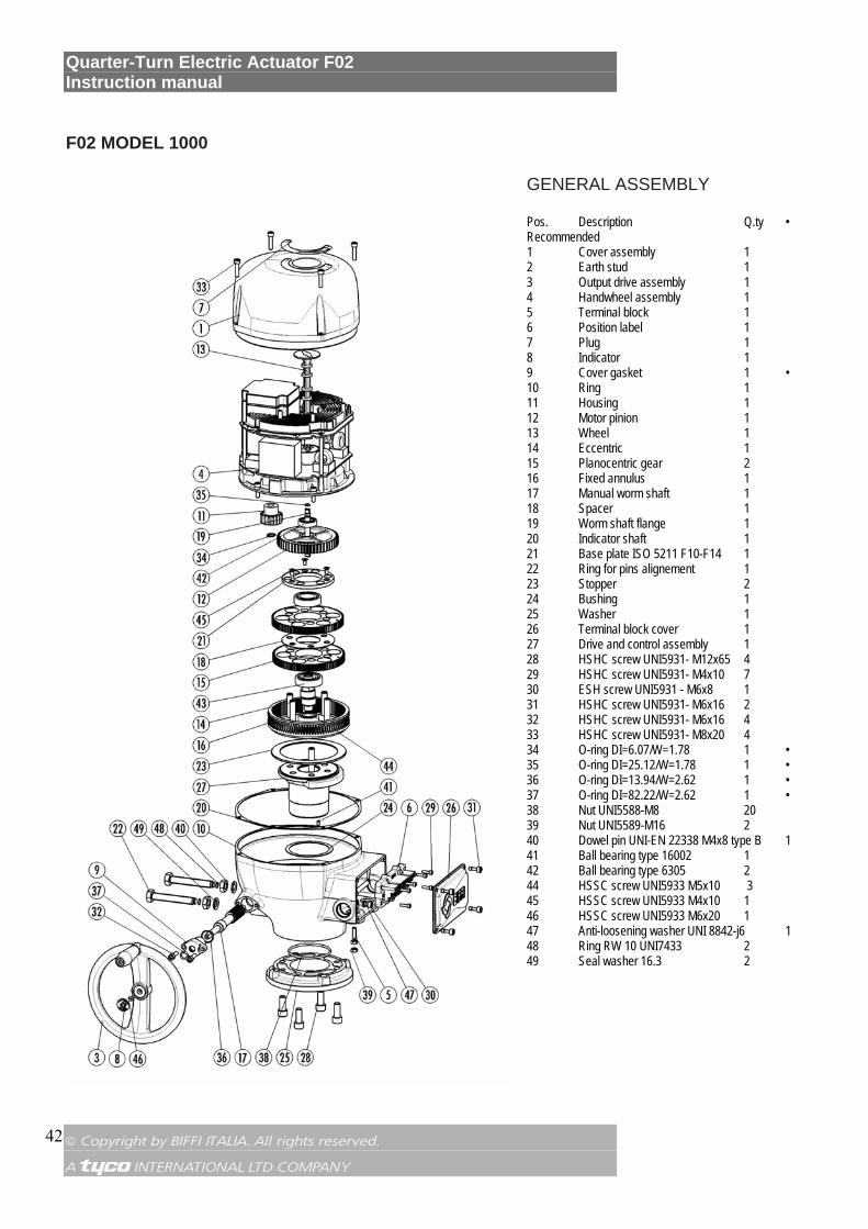
F02 MODEL 1000
GENERAL ASSEMBLY Pos. Description Q.ty • Recommended 1 Cover assembly 1 2 Earth stud 1 3 Output drive assembly 1 4 Handwheel assembly 1 5 Terminal block 1 6 Position label 1 7 Plug 1 8 Indicator 1 9 Cover gasket 1 • 10 Ring 1 11 Housing 1 12 Motor pinion 1 13 Wheel 1 14 Eccentric 1 15 Planocentric gear 2 16 Fixed annulus 1 17 Manual worm shaft 1 18 Spacer 1 19 Worm shaft flange 1 20 Indicator shaft 1 21 Base plate ISO 5211 F10-F14 1 22 Ring for pins alignement 1 23 Stopper 2 24 Bushing 1 25 Washer 1 26 Terminal block cover 1 27 Drive and control assembly 1 28 HSHC screw UNI5931- M12x65 4 29 HSHC screw UNI5931- M4x10 7 30 ESH screw UNI5931 - M6x8 1 31 HSHC screw UNI5931- M6x16 2 32 HSHC screw UNI5931- M6x16 4 33 HSHC screw UNI5931- M8x20 4 34 O-ring DI=6.07/W=1.78 1 • 35 O-ring DI=25.12/W=1.78 1 • 36 O-ring DI=13.94/W=2.62 1 • 37 O-ring DI=82.22/W=2.62 1 • 38 Nut UNI5588-M8 20 39 Nut UNI5589-M16 2 40 Dowel pin UNI-EN 22338 M4x8 type B 1 41 Ball bearing type 16002 1 42 Ball bearing type 6305 2 44 HSSC screw UNI5933 M5x10 3 45 HSSC screw UNI5933 M4x10 1 46 HSSC screw UNI5933 M6x20 1 47 Anti-loosening washer UNI 8842-j6 1 48 Ring RW 10 UNI7433 2 49 Seal washer 16.3 2
Quarter-Turn Electric Actuator F02 Instruction manual
© Copyright by BIFFI ITALIA. All rights reserved. A !"£$ INTERNATIONAL LTD COMPANY
43
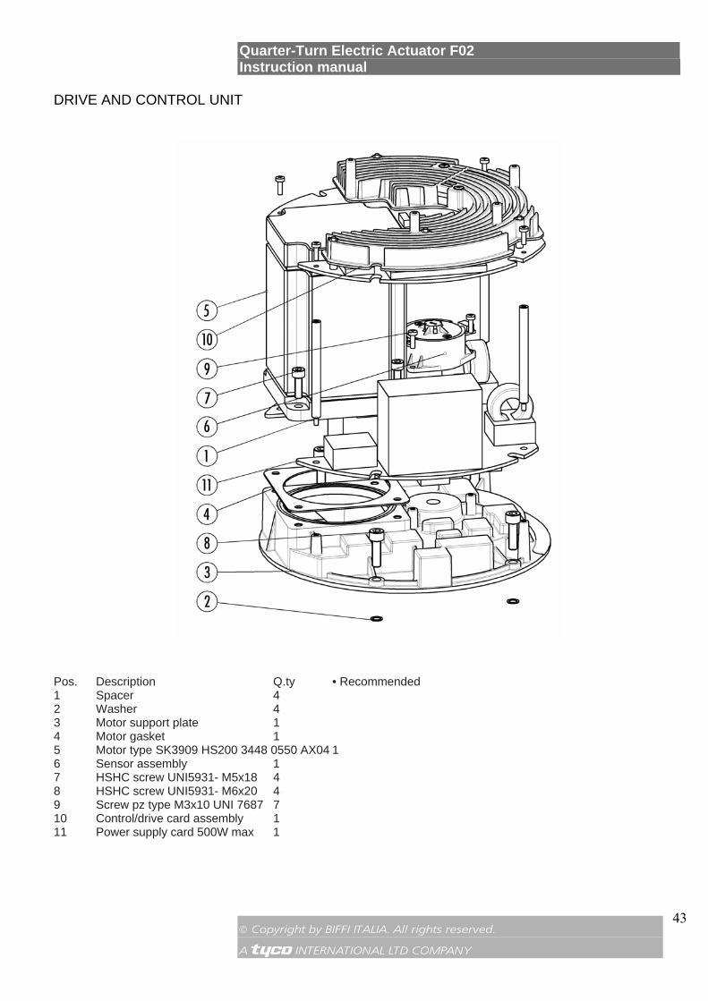
DRIVE AND CONTROL UNIT
Pos. Description Q.ty • Recommended 1 Spacer 4 2 Washer 4 3 Motor support plate 1 4 Motor gasket 1 5 Motor type SK3909 HS200 3448 0550 AX04 1 6 Sensor assembly 1 7 HSHC screw UNI5931- M5x18 4 8 HSHC screw UNI5931- M6x20 4 9 Screw pz type M3x10 UNI 7687 7 10 Control/drive card assembly 1 11 Power supply card 500W max 1