f10 vision sensor f10 - farnell element14 | electronic ... · f10 vision sensor f10 affordable f10...
TRANSCRIPT

F10 Vision Sensor F10
Affordable F10 Vision Sensor withOne-Touch Setup Requires NoProgramming
Ensures fast, accurate inspections suchas label pattern match, print verification,label placement, and conformity (rejectsupside-down, tilted or double labels)
Offers adaptability with 3 selectableinspection areas
F10 Sensor includes a controller,camera, light source, and light guide
Ordering Information PATTERN MATCHING AMPLIFIER
Item Description Output type Part number
F10-C10/-C15 Pattern Matching Amplifier Pattern measurement NPN F10-C10
PNP F10-C15
F10-C11/-C16 Pattern Matching Amplifier Pattern measurement only,or selectable pattern andplain measurement
NPN F10-C11
PNP F10-C16

F10F10
2
HEAD
Item Sensing area Setting distance Part number
F10-S30 Head 25 mm x 20 mm(0.98 in x 0.79 in)
100 ± 10 mm(3.94 ± 0.39 in)
F10-S30
F10-S15 Head 12 mm x 10 mm(0.47 in x 0.39 in)
50 ± 5 mm(1.96 in x 0.20 in)
F10-S15
Specifications PERFORMANCE SPECIFICATIONS — F10-C10/-C15 AMPLIFIERS
Item F10-C10 F10-C15
Output type NPN PNP
Measurement item Pattern measurement
Number of models 1
Automatic teaching function Yes
Model size Normal or wide mode (selectable)
Measurement processingtime
3.6 ms in normal mode and 10.8 ms in wide mode (continuous operation)
Output signal (2 points) Control output and enable output: NPN opencollector with load current of 50 mA max. andresidual voltage of 1.2 V max.
Control output and enable output: PNP opencollector with load current of 50 mA max. andresidual voltage of 2.0 V max.
Input signal (4 points) External trigger input (with minimum pulse width of1 ms), continuous measurement input, movingobject teaching input, or stationary object teachinginput.Input is ON: Short-circuited to 0 V with short-circuitcurrent of 1 mA max. or 1.5 V max.Input is OFF: Open or input voltage of 5 V min.(Max. input voltage: 26.4 VDC)
External trigger input (with minimum pulse width of1 ms), continuous measurement input, movingobject teaching input, or stationary object teachinginput.Input is ON: Short-circuited to Vcc or 9 V min. withmax. input voltage of 26.4 VDC.Input is OFF: Open or input voltage of 5 V max.
Head interface (1 channel) Available Head: F10-S30 or F10-S15
Indicators Result indicator: 1 orange LEDLevel indicators: 8 green LEDsThreshold indicators: 7 red LEDs
Operation interface Teaching button (TEACH), SELECT buttons (UP/DOWN), mode selector (TEACH/MON/RUN),auto-teaching selector (OFF/ON), and model size selector (NORMAL/WIDE)

F10 F10
3
PERFORMANCE SPECIFICATIONS — F10-C11/-C16 AMPLIFIERS
Item F10-C11 F10-C16
Output type NPN PNP
Measurement item Pattern measurement only or pattern or plain measurement (selectable)
Number of models 1
Automatic teaching function Yes
Model size Normal or wide mode (selectable), disabled in plain measurement operation
Measurement processing time Pattern measurement: 3.6 ms in normal mode and 10.8 ms in wide mode (continuous operation)Plain measurement: 7.2 ms in continuous operation
Output signal (2 points) Control output and enable output: NPN opencollector with load current of 50 mA max. andresidual voltage of 1.2 V max.
Control output and enable output: PNP opencollector with load current of 50 mA max. andresidual voltage of 2.0 V max.
Input signal (4 points) External trigger input (with minimum pulse widthof 1 ms), continuous measurement input, movingobject teaching input, or stationary objectteaching input.Input is ON: Short-circuited to 0 V withshort-circuit current of 1 mA max. or 1.5 V max.Input is OFF: Open or input voltage of 5 V min.(Max. input voltage: 26.4 VDC)
External trigger input (with minimum pulse widthof 1 ms), continuous measurement input, movingobject teaching input, or stationary objectteaching input.Input is ON: Short-circuited to Vcc or 9 V min.with max. input voltage of 26.4 VDC.Input is OFF: Open or input voltage of 5 V max.
Head interface (1 channel) Available Head: F10-S30 or F10-S15
Indicators Result indicator: 1 orange LEDLevel indicators: 8 green LEDsThreshold indicators: 7 red LEDsStatus indicators: 3 green LEDs
Operation interface Teaching and display button (TEACH/DISPLAY), SELECT buttons (UP/DOWN), measurement itemselector (PATT/PLN or PATT), mode selector (TEACH/MON/RUN), auto-teaching selector (OFF/ON),and model size selector (NORMAL/WIDE)
GENERAL SPECIFICATIONS — F10-C10/-C15 OR F10-C11/-C16 AMPLIFIERS
Operating temperature 0°C to 50°C (32°F to 122°F)
Operating humidity 35% to 85% (with no condensation)
Storage temperature –25°C to 65°C (–13°F to 149°F) with no icing
Operating environment With no corrosive gas
Input power supply 24 VDC ± 10% (with ripple)
Current consumption 300 mA max.
Insulation resistance 20 MΩ min. (at 500 VDC)
Dielectric strength 1,000 VAC at 50/60 Hz for 1 min
Degree of protection IEC60529 IP40
Vibration resistance 10 to 150 Hz, 0.75-mm single amplitude or 100 m/s2 (10G) max. for 32 min each in X, Y, and Zdirections
Shock resistance Peak acceleration: 300 m/s2 (30G) 3 times each in X, Y, and Z directions
Cable length 2 m
Casing material ABS
Weight Approx. 200 g (including cable)
Note: An F10-C10/-C15 or F10-C11/-C16 Amplifier connects to one F10-S30 or F10-S15 Head. Teach and threshold level adjustmentswill be required again if the Head is replaced.

F10F10
4
HEADSOptical and Lighting System Specifications
Item F10-S30 F10-S15
Appearance
Sensing distance 100 ± 10 mm 50 ± 5 mm
Sensing area 25 mm x 20 mm 12 mm x 10 mm
Guide light projection size A: 25 mm (0.98 in)B: 20 mm (0.79 in)C: 8 mm (0.31 in)D: 6 mm (0.24 in)E: 20 mm (0.79 in)
A: 12 mm (0.47 in)B: 10 mm (0.39 in)C: 4 mm (0.16 in)D: 3 mm (0.12 in)E: 10 mm (0.39 in)
Built-in lens Focus: f9.8 (fixed)Diaphragm: F2.8 (fixed)
Object lighting method Pulse lighting (pulse width is synchronized with electronic shutter in operation)
Object light source 8 red LEDs 8 green LEDs
Main object color combination Black and white, green and white, blue andwhite, and red and black
Black and white, red and white, green andwhite, blue and white, green and black, andblue and black
Guide light projection source 1 green LED 1 blue LED
Guide light projection method Pulse lighting
Camera Image Performance Specification
Item F10-S30 F10-S15
Camera image element 1/5-inch CCD
Shutter function Electronic shutter at a speed range between 1/34722 and 1/2894 s (automatically setduring teaching)

F10 F10
5
GENERAL SPECIFICATIONS — F10-S30/-S15 HEADS
Operating temperature 0°C to 40°C (32°F to 104°F)
Operating humidity 35% to 85% (with no condensation)
Storage temperature –25°C to 60°C (–13°F to 140°F) with no icing
Operating environment With no corrosive gas
Input power supply 18 VDC ± 10% (provided from amplifier)
Current consumption 150 mA max.
Insulation resistance 20 MΩ min. (at 500 VDC)
Dielectric strength 1,000 VAC at 50/60 Hz for 1 min
Degree of protection IEC60529 IP64
Vibration resistance (with mounting bracket attached)
10 to 150 Hz, 0.75-mm single amplitude or 100 m/s2 (10G) max. for 32 min each in X, Y,and Z directions
Shock resistance(with mounting bracket attached)
Peak acceleration: 300 m/s2 (30G) 3 times each in X, Y, and Z directions
Cable length 2 m
Casing material Case: Aluminum die castFront cover: Acrylic resin
Weight Approx. 300 g (including cable)
Accessories provided A dedicated mounting bracket, two M4 screws, and two M4 washers
Application Examples F10-C11/-C16 AMPLIFIER
Teaching
Plain without colorsor patterns
Color Stain Pattern
Patternmeasurement
Pattern measurement
Plain measurement
Measures Plain Objects Without Colors or Patterns
Each object is discriminated accordingto the deviation and average density. Aplain object without colors or patternswill be detected if a sample of the plainobject is registered as a model byteaching.
Discriminates Improper Objects
Plain or pattern measurement is applicableto the discrimination of improper objects.If a sample of a plain or patterned object isregistered as a model by teaching, theSensor will operate and automaticallydetect objects identical to the model.

F10F10
6
Engineering Data
F10-S30 DATA CHARACTERISTICS
Rotation Characteristics Area Position Characteristics (in X Direction)
Leve
l ind
icat
or
Area Position Characteristics (in Y Direction)
Angle of rotation In X direction (mm) In Y direction (mm)
Leve
l ind
icat
or
Leve
l ind
icat
or
• The following data is obtained on the basisof sample target objects, each of which is aslarge as this size (A). (Typical example)
• The Head is inclined 15° to the target object.
Rotation
Shi
ft an
gle
Shift angle
Y+
Y–X+ X–
+–
–20 –15 –10 –5 0 5 10 15 20 –8 –4 0 4 8 –6 –3 0 3 6
876543210
(W. D. 100 mm) (W. D. 100 mm) (W. D. 100 mm)
876543210
876543210
Distance Characteristics Shift Angle Characteristics(in X Direction)
Leve
l ind
icat
or
Shift angle in X direction (°)
Leve
l ind
icat
or
Leve
l ind
icat
or
Shift Angle Characteristics(in Y Direction)
Shift angle in Y direction (°)
–30 –20 –10 0 10 20 30–30 –20 –10 0 10 20 30 80 85 90 95 100 105 110 115 120
(W. D. mm)(W. D. 100 mm) (W. D. 100 mm)
876543210
876543210
876543210

F10 F10
7
F10-S15 DATA CHARACTERISTICS
• The following data is obtained on the basis of sample target objects, each ofwhich is as large as this size (A). (Typicalexample)
• The Head is inclined 15° to the target object.
Rotation
Shi
ft an
gle
Shift angle
Y+
Y–X+ X–
+ –
Rotation Characteristics Area Position Characteristics (in X Direction)
Leve
l ind
icat
or
Area Position Characteristics (in Y Direction)
Angle of rotation In X direction (mm) In Y direction (mm)
Leve
l ind
icat
or
Leve
l ind
icat
or
–4 –3 0 2 4–20 –15 –10 –5 0 – 5 –10 –15 –20 –2.5 –1.3 0 1.25 2.5
(W. D. 50 mm)(W. D. 50 mm)(W. D. 50 mm)
876543210
876543210
876543210
Distance Characteristics Shift Angle Characteristics(in X Direction)
Leve
l ind
icat
or
Shift angle in X direction (°)
Leve
l ind
icat
or
Leve
l ind
icat
or
Shift Angle Characteristics(in Y Direction)
Shift angle in Y direction (°)
30 35 40 45 50 55 60 65 70 –30 –20 –10 0 10 20 30 –30 –20 –10 0 10 20 30
(W. D. 50 mm)
(W. D. mm)
876543210
876543210
876543210

F10F10
8
NomenclatureNote: 1. An F10-C10/-C15 or F10-C11/-C16 Amplifier connects to a single F10-S30 or F10-S15 Head.
2. If the Head is replaced, teaching and threshold-level adjustments will be required again. (This applies to an F10-C10/-C15 orF10-C11/-C16 Amplifier.)
Level IndicatorsIndicates the level ofmatching with regis-tered models.
Teaching Button
Mode Selector (TEACH/MON/RUN)TEACH: TEACH modeMON: MONITOR modeRUN: RUN mode
Model Size Selector(NORMAL/WIDE)
Result IndicatorOK: ONNG: OFF
Threshold Indicators
SELECT Buttons (UP/DOWN )
Auto-Teaching Selector (A.TEACH OFF/ON)ON: Teaching area automatic selectionOFF: Teaching area fixed
F10-C10/-C15 AMPLIFIER
Display Button (TEACH/DISPLAY)
Teaching Button(TEACH/DISPLAY)
Measurement Item Selector (PATT/PLN or PATT)
F10-C11/-C16 AMPLIFIER
Threshold Indicators
Level IndicatorsIndicates the levelof matching withregistered models.
Model Size Selector(NORMAL/WIDE)
Mode Selector (TEACH/MON/RUN)TEACH: TEACH modeMON: MONITOR modeRUN: RUN mode
Auto-Teaching Selector ON: Teaching area automatic selectionOFF: Teaching area fixed
SELECT Buttons
Result IndicatorOK: ONNG: OFF
Status Indicators

F10 F10
9
F10-S30 HEAD
Guide light (green)
Object lighting (red)
F10-S30 with 2-mstandard cable
Sensing side
Teaching area
Sensing area (field of vision)
20 mm
100 ±10 mm 25 mm
F10-S15 HEAD
Guide light (blue)
Object lighting (green)F10-S15 with 2-mstandard cable
Sensing side
Teaching area
Sensing area (field of vision)
50 ±5 mm 12 mm
10 mm
Installation
MOUNTING ANGLE
• Incline the Head by 15° and mount the Head so that noregular reflected light affects the Sensor.
• To mount the Head, use the Mounting Bracket provided.
F10-S30 F10-S15
F10-S30: 100±10 mm F10-S15: 50±5 mm

F10F10
10
Operation I/O CIRCUIT DIAGRAMF10–C10/-C11 NPN Amplifier Models
Level indicators(8-level greenLEDs)
Result indicator (1-level orangeLED)
Amplifiermain circuit
Threshold indicators (7-level red LEDs)
Shielded line
Load
Load
Brown (Vcc)
Black
Orange
Yellow
Purple
Pink
White
Blue (GND)
21.6 to 26.4 VDC
OUTPUT
ENAB
FG
Status indicator(F10-C11 only)
For normal operation, ground or connect the GND terminal to 0 V.
Signal Function Reference
OUTPUT Control output Setting Procedure, RUN Mode
ENAB Enabled output
g ,
S_TEACH Stationary object teaching input
M_TEACH Moving object teaching input
TRIG Measurement trigger input
CONT Continuous measurement input
• All input signals are enabled in RUN mode only.
• The shielded wire is not connected to the interior or casing.

F10 F10
11
F10-C15/-C16 PNP Amplifier Models
Level indicators(8-level greenLEDs)
Result indicator (1-level orangeLED)
Amplifiermain circuit
Threshold indicators(7-level red LEDs)
Shielded line
Load
Brown (Vcc)
Black
Orange
Yellow
Purple
Pink
White
Blue (GND)
21.6 to 26.4 VDC
Load
FG
Status indicator(F10-C16 only)
For normal operation, ground or connect the shielded cable to 0 V.
Signal Function Reference page
OUTPUT Control output Setting Procedure, RUN Mode
ENAB Enabled output
g ,
S_TEACH Stationary object teaching input
M_TEACH Moving object teaching input
TRIG Measurement trigger input
CONT Continuous measurement input
• All input signals are enabled in RUN mode only.
• The shielded wire is not connected to the interior or casing.

F10F10
12
F10-C10/-C15 AMPLIFIER SETTING PROCEDUREPattern Registration (TEACH Mode)
Necessary image data as measurement criteria is registered in TEACH mode by using the various selectors and the Teaching Button(numbered 1 through 4 in the following illustration).
Level Indicators
4. Teaching Button
2. Auto-Teaching Selector
Threshold Indicators
3. Model-Size Selector
1. Mode Selector
(Notice the location of:A. TEACH OFFand A. TEACH ON)
The pattern inthe frame isregistered as amodel.
Procedure
1. Set the Mode Selector to TEACH.
2. Set the Auto-Teaching Selector to: A.TEACH OFF.Fixed-area teaching will be performed. Only the patternin the teaching area will be registered.
The most ideal pattern as a model is automatically selected for pattern measurementfrom the measurement range.
Set the Auto-teaching Selector to A.TEACH ON.
The portion the most different in contrast from the background in the sensingrange will be used as a model, although it will not be possible to confirm whatportion is registered at this stage.
Most ideal
Slightly pale
Too pale
The pattern the most different incontrast from the background willbe registered.
Or, set the Auto-teaching Selector to: A.TEACH ON.

F10 F10
13
3. Set the Model-Size Selector to select the mode.
Normal Mode Wide Mode
Sensing AreaThis area isdetected.
Teaching AreaThis area is registeredas a model.
SensingArea – of model 1
SensingArea – of model 2
SensingArea – of model 3
Teaching AreaThis area is dividedinto three portions tobe registered asthree models.
Model 1 Model 2 Model 3
Note: Operate the Sensor in wide mode if the pattern is relatively long in a single direction, such as a manufacturing date, month,and year. Since three models are consecutively processed in the wide mode, the required processing time will be threetimes that of the normal mode.
Teachingarea inwide mode
Linedirection
Teaching area in wide mode
Line direction
Mounting Direction of Sensor in Wide ModeFor target objects that are moving, use the Sensor as shown on the left side in this illustration.
Recommended NotRecommended

F10F10
14
4. Press the Teaching Button after locating the target object in the sensing area.
Checking the Degree ofSuitability for a Model
Teaching Successful Teaching Unsuccessful
Optimumfor a model
Not fit fora model
Locate the target object inthe sensing area so that thedegree of suitability for amodel will be indicated.
Press theteachingbutton.
The level indicators are alllit for 0.5 s and the buzzerbeeps twice.
The threshold indicatorsall flash while the buzzerbeeps four times. Thecontrast is insufficient.Change the location ofthe Sensor and try again.
A.TEACH Set to ON
The pattern close to the edgeof the sensing area will not beregistered as a model. Be sureto locate the pattern as closeas possible to the center of thesensing area.
After the teaching operation, set the Sensor to MONITOR mode for threshold adjustments.Go to Threshold Adjustment/Sample Test (MONITOR Mode).
Note: Do not turn OFF the Sensor before the Sensor is set to MONITOR mode, or the teaching data will be lost.
Recommended NotRecommended
Threshold Adjustment/Sample Test (MONITOR Mode)
The Sensor operates in MONITOR mode for threshold level adjustments and desktop sample tests for object discrimination with no signaloutput. No external output operation signal or input signal is accepted in MONITOR mode.
Level Indicators
1. Mode Selector (TEACH/MON/RUN)
Do not change these settingsin MONITOR mode.
Result Indicator
Threshold Indicators
2. SELECT Buttons

F10 F10
15
Procedure
1. Set the Mode Selector to MON. Measurement continues as long as the selector is set to MON. On the basis of the registered model,the level indicator indicates the degree of conformance of the target object.
Closer to model inappearance
The closer to the model in appearance,the higher the level.
Not close to modelin appearance
If no target object is within the sensing areaor if the target object is greatly different from
the model, the level will be lower.
2. Press the SELECT Buttons to adjust the threshold. Adjust the threshold to the most suitable level by monitoring the level indicator.
Closer to model inappearance
Turns ON if the measurement value ishigher than the threshold.
Not closer tomodel in appearance
Turns OFF if the measurement valueis lower than the threshold.
Thresholdvalue
Thresholdvalue
The result indicatorand output signal
are ON.
The result indicatorand output signal
are OFF.
After the above threshold adjustments, return to TEACH mode again if the models have not been registered correctly.
Go to Pattern Registration (TEACH Mode). Details are in previous subsection.
If the adjustments are OK, the Sensor is ready to operate in RUN mode.
Go to Measurement Execution (RUN Mode). Explanation follows.
Note: 1. Any threshold changed will be entered only when the Mode Selector is set to RUN or TEACH.2. In wide mode, the model with the lowest degree of conformance out of the three models is used for discrimination.

F10F10
16
1. Mode Selector
Measurement Execution (RUN Mode)
The Sensor performs measurement according to the external signal input in RUN mode.
Procedure
1. Set the Mode Selector to RUN.
Relationship between the F10 I/O terminal operations and ON/OFF indications in the timing charts are as shown in the following table.
Signal Indication in timing charts NPN (F10-C10/-C11) PNP (F10-C15/-C16)
InputTRIG (pink)CONT (white)
ON GND Vcc
CONT (white)S_TEACH (yellow)M_TEACH (purple)
OFF OPEN OPEN
OutputOUTPUT (black)
ON GND VccOUTPUT (black)ENAB (orange) OFF Vcc GND
CONT ModeIn CONT mode, the Sensor is in sensing operation repeatedlywhile the CONT signal is ON. The measurement result isrenewed once per measurement cycle, and output.
Measurement cycle: ToutNormal mode: 3.6 msWide mode: 10.8 ms
TRIG ModeThe Sensor in TRIG mode is used for object measurementonly once in synchronization with the rising edge of the TRIGsignal and the result is output.
Period from trigger input to output refreshment: ToutNormal mode: 14.4 msWide mode: 21.6 ms
In TRIG measurement operation, the ENAB signal is ONwhen the measurement result is renewed.
Note: 1. The minimum ON width of the TRIG signal is 1 ms.2. The OUTPUT signal is kept on hold until the next
measurement result is renewed.

F10 F10
17
External Teaching in RUN ModeIn RUN mode, a model can be registered by external signal inputusing either of the two methods described below.
Note: The data of the model is stored in the EEPROM when theteaching process of the Sensor completes. Do not turnOFF the Sensor during the teaching process. If the Sen-sor is turned OFF, an EEPROM data error will result whenthe Sensor is turned ON again. In this case, perform prop-er teaching and threshold level adjustments again.
Stationary Object Teaching (S_TEACH)
Stationary object teaching is performed with the TRIG signalinput or CONT signal input after external S_TEACH signal input.Because of this, do not move the object until teaching iscompleted.
1. Provide S_TEACH signal input.2. Check that the ENAB signal is OFF.3. Check that the stationary object is in the teaching area (or in
the sensing area if A.TEACH is set to ON).4. Provide external CONT or TRIG signal input.5. After teaching is completed, the ENAB signal will turn ON. At
that time, check the status of the OUTPUT signal.6. The OUTPUT signal will be ON if teaching is successfully
completed.7. The OUTPUT signal will be OFF if teaching is unsuccessful.8. Turn the S_TEACH signal OFF to complete the teaching
process. If teaching has been unsuccessful, the Sensor willremain in the previous status, so you must perform teachingagain.
Teaching in process
ONOFF
ONOFF
OFF
ON
OFF
ON
S-TEACH
CONT or TRIG
ENAB
OUTPUT
(1) (8)
(4)
(2) (5)
(7)
(6)
Moving Object Teaching (M_TEACH)
Moving object teaching is performed by using more than oneobject. Perform this teaching if the target objects cannot bestopped. After M_TEACH signal input, this teaching requires sixprocesses in synchronization with external trigger input. TheSensor will not be in detection operation during the teachingprocess. External trigger input is ignored after it turned ON sixtimes.
1. Provide external M_TEACH signal input.2. Check that the ENAB signal is OFF.3. Provide TRIG signal input in synchronization with the mea-
surement timing of the target objects used for teaching.4. Repeat step 3 six times.5. After teaching is completed, the ENAB signal will turn ON. At
that time, check the status of the OUTPUT signal.6. The OUTPUT signal will be ON if teaching is successfully
completed.7. The OUTPUT signal will be OFF if teaching is unsuccessful.8. Turn the M_TEACH signal OFF to complete the teaching
process. If the teaching has been unsuccessful, the Sensorwill remain in the previous status; so, you must performteaching again. The teaching operation will be disabled if theM_TEACH signal is turned OFF during the teaching process.
Teaching in process
ONOFF
ONOFF
OFF
ON
OFF
ON
M-TEACH
TRIG
ENAB
OUTPUT
50 ms min.
(1) (8)
(3) (4)
(2) (5)
(7)
(6)
Enable Output
Enable output turns ON when the Sensor is ready to be insensing operation. For this reason, enable output will turnOFF if the mode selector is set to TEACH or MON.
Enable output is OFF in the following cases in RUN mode.
1. The Sensor is in teaching process with external teachinginput.
2. The Sensor is in sensing operation with TRIG signalinput.
3. No teaching data has been registered.4. The hardware fails.

F10F10
18
4. Model Size Selector(NORMAL/WIDE)
Result Indicator
Status Indicators
Threshold Indicators
SELECT Buttons
1. Mode Selector (TEACH/MON/RUN)
3. Auto-teaching Selector (OFF/ON)
Display Button(TEACH/DISPLAY)
Teaching Button(TEACH/DISPLAY)
2. Measurement Item Selector(PATT/PLN or PATT)
Level Indicators
F10-C11/-C16
Normal Mode Wide Mode
Sensing AreaThis area isdetected.
Teaching AreaThis area is registeredas a model.
SensingArea—of model 1
SensingArea—of model 2
SensingArea—of model 3
Teaching AreaThis area is dividedinto three portions tobe registered as threemodels.
Model 1 Model 2 Model 3
Necessary image data, as measurement criteria, is registered in the TEACH mode.
Procedure1. Set the Mode Selector to TEACH.
2. Set the Measurement Item Selector to PATT/PLN.Pattern measurement or plain measurement will be selected automatically (according to the registered model), if the selector is set to PATT/PLN. The F10-C11/-C16 will be in pattern measurement operation like the F10-C10/-C15 if the selector is set to PATT.
3. Set the Auto-teaching Selector to A.TEACH ON.The most ideal pattern as a model will be selected automatically for pattern measurement from the measurement range.
4. Set the Model size Selector.
TEACH Mode
Teachingarea inwide mode
Linedirection
Teachingarea inwide mode
Line direction
Mounting Direction of Sensor in Wide ModeFor target objects that are moving, use the Sensor, as shown on the left side below.
Recommended Not Recommended
Note: Operate the Sensor in widemode if the pattern is relativelylong in a single direction, such
as a manufacturing date, month,and year. Since three modelsare consecutively processed inthe wide mode, the requiredprocessing time will be threetimes that of the normal mode.

F10 F10
19
5. After locating the target object in the sensing area, press the Teaching Button. Pattern measurement or plain measurement is automatically determined from the background of the sensing area and the deviation of the target object.
Pattern Measurement Plain MeasurementThe deviation level will become high if the targetobject has a pattern. If the deviation level is higherthan the set level of measurement item selection,pattern measurement will be performed.
The deviation level will be set to low if the target object has no pattern. If the set level of measurementitem selection is higher than the deviation level, plainmeasurement will be performed.
Approx 5.0 mm (F10-S30)Approx 2.5 mm (F10-S15)
Plain measurement will be performed if the pattern isclose to the edge of the sensing area.
The deviation and average density in the teaching areaare registered in the above example. In other words,the sensing area is restricted so that the pattern closeto the edge will not influence the results of object discrimination.
Teaching is performed in the areaenclosed by dotted lines inside thesensing area. The pattern close tothe edge of the sensing area is notregistered as a model because sucha pattern may not be always locatedin the sensing area and accuratemeasurement cannot be performed.In this example, the deviation levelin the area enclosed by the dottedlines is small. Therefore, plainmeasurement will be performed.
Teaching OK
The level indicators are all lit for 0.5 s, and thebuzzer sounds twice.
Teaching NG
The threshold indicators all flash while the buzzersounds four times.
• The set level of measurement item selection isincreased or decreased by pressing theSELECT buttons. Adjust the level according tothe background and deviation. The level is fac-tory-set between 2 and 3.
• If the object has some light-color lines or light-color patterns, pattern measurement may beperformed. In this case, by increasing the setlevel of measurement item selection, plain mea-surement will be performed.
Sensing area
The portion with the highestdeviation is registered as amodel.
High
Deviation
Low
Measurementitem selectionlevel
Automaticselection
Sensingarea
The deviation and average density in the areaenclosed by dotted lines are registered. Thedotted lines are not projected.
High
Deviation
LowMeasurementitem selectionlevel
TeachingArea

F10F10
20
MONITOR Mode
The F10-C11/-C16 operates in MONITOR mode for threshold level adjustments and desktop sample tests for object discrimination with nosignal output. No external input is accepted in MONITOR mode.
Procedure
1. Set the operation mode selector to MON. Measurement continues as long as the selector is set to MON.
2. In plain measurement operation, the Level Indicator is switched over from DEV to DEN or DEN to DEV whenever the display button ispressed.
Status Indicator
Pattern measurement
Plain measurement
Degree of conformity with model
Deviation
Difference from average density at teaching
Similar tomodel pattern
Not similar tomodel pattern
The more similar to the model patternthe object is, the higher the levelindicator reading will be.
Low deviation
High deviation
The lower the deviation is, the higherthe level indicator reading will be.
Less differentfrom teachingdensity
Largely differ-ent from teach-ing density
The smaller the difference is from theteaching average density, the higherthe level indicator reading will be.
Averagedensity
PATT is lit DEV is lit DEN is lit

F10 F10
21
3. Press the SELECT Buttons to adjust the threshold. Adjust the threshold to the most suitable level by monitoring the level indicator.
Pattern measurement: The model with the lowest conformity level out of the three models is used for discrimination in widemode.
Plain measurement: Set both deviation (DEV) threshold and average density (DEN) threshold. The result indicator and outputsignal will be OFF if either one of the sensing objects is lower than the threshold.
Any threshold changes will not be saved unless the mode selector is set to RUN or TEACH.
Threshold Threshold
Will turn ON if the measurementvalue is higher than the threshold.
Will turn OFF if the measurementvalue is lower than the threshold.
The result indicator andoutput signal are ON.
The result indicator andoutput signal are OFF.
RUN Mode
Measurement is performed according to the external signal input in RUN mode. Operate in CONT mode for object detection. TRIG modeis used for object inspection in combination with a timing switch.
Procedure1. Set the Mode Selector to RUN to start measurement. There is no difference in operation between the F10-C11/-C16 and
F10-C10/-C15 in RUN mode.
F10F10
22
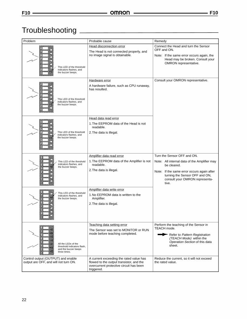
TroubleshootingProblem Probable cause Remedy
This LED of the thresholdindicators flashes, andthe buzzer beeps.
Head disconnection error
The Head is not connected properly, andno image signal is obtainable.
Connect the Head and turn the SensorOFF and ON.
Note: If the same error occurs again, theHead may be broken. Consult yourOMRON representative.
This LED of the thresholdindicators flashes, andthe buzzer beeps.
Hardware error
A hardware failure, such as CPU runaway,has resulted.
Consult your OMRON representative.
This LED of the thresholdindicators flashes, andthe buzzer beeps.
Head data read error
1.The EEPROM data of the Head is notreadable.
2.The data is illegal.
This LED of the thresholdindicators flashes, andthe buzzer beeps.
Amplifier data read error
1.The EEPROM data of the Amplifier is notreadable.
2.The data is illegal.
Turn the Sensor OFF and ON.
Note: All internal data of the Amplifier maybe cleared.
Note: If the same error occurs again afterturning the Sensor OFF and ON,consult your OMRON representa-tive.
This LED of the thresholdindicators flashes, andthe buzzer beeps.
Amplifier data write error
1.No EEPROM data is written to theAmplifier.
2.The data is illegal.
All the LEDs of thethreshold indicators flash,and the buzzer beepsthree times.
Teaching data setting error
The Sensor was set to MONITOR or RUNmode before teaching completed.
Perform the teaching of the Sensor inTEACH mode.
Refer to Pattern Registration(TEACH Mode) within the Operation Section of this datasheet.
Control output (OUTPUT) and enableoutput are OFF, and will not turn ON.
A current exceeding the rated value hasflowed to the output transistor, and theovercurrent protective circuit has beentriggered.
Reduce the current, so it will not exceedthe rated value.

F10 F10
23
DimensionsUnit: mm (inch)
F10-C AMPLIFIERS
F10-C11/-C16 only
F10-C11/-C16 only
5-dia. Vinyl-insulated roundcable, 8 cores (0.12 dia. x 18),standard length: 2 m
Mounting Dimensions
Two, M4
80 (3.15)89 (3.50)
98 (3.86)
21(0.83)
30.8 (1.21)
25(0.98)
89 (3.50)
21(0.83)
35.2 (1.39)
30 (1.18)
25(0.98)
55(2.17)
F10-C11/-C16 only

F10F10
24
Ferrite core
14.7 (0.58) dia. connector
Two, M4pan-headscrews
The Mounting Bracket can beattached to this side as well.
Mounting HoleMounting HoleDimensions
Two, M4
5.8-dia. Vinyl-insulatedround cable, 7 cores (0.16 dia. x 7), standard length: 2 m
Mounting Dimensions
125 (4.92)
16.5(0.65)
30(1.18)
33(1.30)
16.5(0.65)
52(2.05)
22(0.87)
2(0.08) 37 (1.46) 21
(0.83)
16.7(0.66)
16.5(0.65)30
(1.18)
33.4(1.32)
33(1.30)
70 (2.76)
75 (2.95)
37(1.46)
38.7(1.52)
37 ± 0.2 (1.46 ± 0.008)
54 (2.13)
43 (1.69)
F10-SHEADS
Protrudingpart
R1 max.
MOUNTING BRACKET(INCLUDED)
25.5 (1.00)
3-R2.25
5.5(0.22)
3(0.12)
3(0.12)37
(1.46)
22(0.87)
43 (1.69)
43 (1.69)
54 (2.13)
5.5(0.22)
3-R2.25
22(0.87)
37(1.46)
3(0.12)

F10 F10
25
Precautions
APPROPRIATE USEThis product must be operated according to the performancespecifications described in the operation manuals.
Applications Not Described in the ManualsConsult your OMRON representative before using the productunder conditions which are not described in the manual(s) orbefore applying the product to nuclear control systems, railroadsystems, aviation systems, vehicles, combustion systems,medical equipment, amusement machines, safety equipment,and other systems, machines, and equipment that may have aserious influence on lives and property if used improperly. Makesure that the ratings and performance characteristics of theproduct are sufficient for the systems, machines, and equipment,and be sure to provide the systems, machines, and equipmentwith double safety mechanisms.
Caution!
Guidelines for Avoiding Sensor Damage or Malfunction• Do not make mistakes in wiring, such as mistakes in polarity.
• Do not apply voltage exceeding the rated range.
• Do not short-circuit the load.
• Organic solvents may damage the casing of the Amplifier,(which is made of ABS resin) and the transparent front panelof the Head (made of acrylic resin). Do not use paint thinneror any other organic solvent to clean the product.
• Be sure that the cables, Units, and other items with lockingdevices are properly locked into place. (Improper lockingmay result in malfunction.)
CONNECTION• The connector on the Amplifier and the metal screws on the
bottom of the Amplifier are connected internally to 0-V termi-nal of the Amplifier.
• Make sure that the length of the Amplifier cable is no longerthan 20 m.
• Make sure that the tightening torque of each screw on theHead and Amplifier is no greater than 1.2 N m.
CORRECT OPERATION• Do not disconnect or connect the Head while the Sensor is
turned ON.
• The F10-S30 cannot detect red objects with white back-grounds. Use the F10-S15 instead.
• The F10-S15 cannot detect green objects with white back-grounds. Use the F10-S30 instead.
• The F10-C Amplifier radiates heat. If more than one Unitis installed side-by-side, make sure that there is a minimumspace of 5 mm between adjacent Units, as shown below.
5 mm min.
Amplifiers
AMBIENT OPERATING TEMPERATURE
The ambient operating temperature range of the Amplifier isbetween 0°C and 50°C under the following conditions:
• Provide enough ventilation to the Amplifier. If more than oneUnit is installed side-by-side, provide a ventilation fan forefficient ventilation.
• Do not install the Amplifier close to heat-radiating devicessuch as heaters, transformers, and high-capacity resistors.
• If power lines with high current for motors are wired close tothe Amplifier, make sure that the Amplifier operates normallyand take proper measures, so the power lines will not have abad influence on the operation of the Amplifier.

F10 F10
Cat. No. D089-E3-1 10/99/10M, 500 Specifications subject to change without notice. Printed in U.S.A.
OMRON ELECTRONICS, INC.One East Commerce DriveSchaumburg, IL 60173
NOTE: DIMENSIONS SHOWN ARE IN MILLIMETERS. To convert millimeters to inches divide by 25.4.
1-800-55-OMRON
OMRON CANADA, INC.885 Milner AvenueScarborough, Ontario M1B 5V8
416-286-6465