f2 manual rev1 11
TRANSCRIPT

8/6/2019 F2 Manual Rev1 11
http://slidepdf.com/reader/full/f2-manual-rev1-11 1/60
3771 Monarch Street • Frederick, CO 80530 • www.inteccorp.com
Local: (303) 833-6644 • Fax: (303) 833-6650 • Toll Free: (800) 666-1611
Instruction Manual

8/6/2019 F2 Manual Rev1 11
http://slidepdf.com/reader/full/f2-manual-rev1-11 2/60

8/6/2019 F2 Manual Rev1 11
http://slidepdf.com/reader/full/f2-manual-rev1-11 3/60
Machine Information ........................................................................2
Contacting Intec ................................................................................3
Introduction........................................................................................4
Specifications......................................................................................5
Overview ............................................................................................6
How the System Works Together ....................................................9
Safety First ......................................................................................11
Set-Up and Operation ....................................................................12
Operational Guidelines ..................................................................15
Sidewall & Insulation Material ......................................................16
Generators and Extension Cords ..................................................18
Maintenance ....................................................................................19
Troubleshooting................................................................................25
Mechanical Drawings......................................................................29
Electrical Drawings ........................................................................35
Claims, Damage or Loss ................................................................48
Returns ............................................................................................50
Receiving Replacement Parts ........................................................51
Warranty ..........................................................................................52
Insulation Terms and Values ..........................................................53
THE FORCE/2Table of Contents
C O N
T E N T S
1D200-0200-00 KL 1/07

8/6/2019 F2 Manual Rev1 11
http://slidepdf.com/reader/full/f2-manual-rev1-11 4/60
M A C H I N
E I N F O R M
A T I O N
2

8/6/2019 F2 Manual Rev1 11
http://slidepdf.com/reader/full/f2-manual-rev1-11 5/60
Phone support:
Available Monday - Friday, excluding holidays. In the United States and Canada, call(800) 666-1611, 7:00 A.M. to 5:00 P.M. Mountain Time. Ask for technical support
and one of our technicians will be glad to help you.
On-site/of f-site r epair support:
Available Monday to F riday, excluding holidays. In the United Sta tes and Canada,
call (800) 666-1611, 7:00 A.M. to 5:00 P .M. Mountain time . For the latest
repair/service center s acr oss the United Sta tes visit our w eb site ,
www.inteccorp.com and go to service centers. All service centers are independently
owned and operated and are not par t of Intec. Consult the near est service centerfor the hours of operation and lead time for repair.
Website support:
Visit our w eb site 24/7 a t www.inteccorp.com and go to the specific model
your w anting inf ormation on, then g o to the tec hnical b ulletins section. The
technical section of the web site is constantly being updated with new information
and technical documents. If you cannot find what you are looking for please contact
us Monday - Friday, excluding holidays, in the United States and Canada, call (800)
666-1611, 7:00 A.M. to 5:00 P.M. Mountain Time. Ask for technical support and one
of our technicians will be glad to help you.
Contact Infor mation:
3771 Monarch Street
Frederick, CO 80530
Ph: 1-303-833-6644
1-800-666-1611
Fax: 1-303-833-6650
E-mail: [email protected]
C O
N T A C T I N G
I N T E C
3
THE FORCE/2Contacting Intec

8/6/2019 F2 Manual Rev1 11
http://slidepdf.com/reader/full/f2-manual-rev1-11 6/60
Your FORCE/2 insulation blowing machine, the product of years of laboratory
and field testing , offers both the contr actor and the homeo wner e xceptionalperformance, total reliability, and ease of use.
It is designed and built to blow-in more than a ton of material per hour. No other
machine in its class can match the performance of the FORCE/2.
Because no insula tion g oes thr ough the blo wer, the FOR CE/2 is a vir tual
workhorse, requiring onl y minimal maintenance . The dir ect dri ve f eature also
means there are no chains for you to adjust or replace, ever.
Following the instr uctions in this man ual,
setting up and operating the FORCE/2 on
the jobsite will be uncomplica ted, quick,
safe, and easy. Once your work is finished,
end-of-the-day clean up is equally efficient.
Exceptional perfor mance. Total reliability.
Ease of use. Those are the reasons why the
FORCE/2 is your best choice.
Rex DeitesfieldPresident
THE Force/2 Insulation Blowing Machine
I N T R O D U
C T I O N
4

8/6/2019 F2 Manual Rev1 11
http://slidepdf.com/reader/full/f2-manual-rev1-11 7/60
THE FORCE/2Specifications
S P E C I F I C A
T I O N S
Height 45" without wheels
501
⁄ 2
" with wheels Width 32"
Weight 283 lbs. without wheels
302 lbs. with wheels
Hopper Capacity 50 lbs.
Hose Size 3"
Blower, 2-stage 105 CFM, 3.6 PSI (AVG) 11.5 amps
116 CFM, 4.5 PSI (AVG) 12.5 amps (Optional)
Agitator Motor 1-1
⁄ 2 hp - 14.5 or 17.2 amps 115 VAC2 hp - 21 AMPS 115 VAC (Optional)
Gear Box Custom, direct drive
Airlock 8" x 10" opening, steel, 6-vane,
cast urethane seals
Electric 115/220 VAC single phase
Agitator 6-blade
Warranty One year limited;
90 days limited on electric,
blower and airlock system
Specifications are subject to change without notice.
5

8/6/2019 F2 Manual Rev1 11
http://slidepdf.com/reader/full/f2-manual-rev1-11 8/60
THE FORCE/2Overview
O V E
R V I E W
6
Main PanelSwitches
Agitator Motor Circuit Breaker
Flange Receptacle(Power Cord)
Variable SpeedBypass Switch
Remote SwitchBlower/ Agitator
Remote ControlReceptacleVariable
Speed Control
FiberglassBale Breaker (Optional)
Agitator

8/6/2019 F2 Manual Rev1 11
http://slidepdf.com/reader/full/f2-manual-rev1-11 9/60
THE FORCE/2Overview, Cont.
O V E
R V I E W
THREE SUBSYSTEMS MAKE UP YOUR FORCE/2:
1. THE AGITATOR AND AIRLOCK. Your FORCE/2 runs on a 1-1 ⁄ 2 or 2 horsepower motor driving an enclosed gearbox. The gearbox drives both
the agitator and airlock components at a constant speed.
2. THE BLOWER MOTOR. Your FORCE/2 is equipped with either
a 105 or 116 CFM tw o-stage blower motor to push the ma terial through the
hose and into the attic with optim um pressur e and output. The blo wer is
connected to the air intake port of the airlock by a plastic hose.
3. ELECTRICAL COMPONENTS. Your FORCE/2 requires two
dedicated 20 amp grounded outlets. A circuit (outlet) rated lower
than 20 AMPS may cause premature tripping at the power source.
Always disconnect the power
cords before beginning any
maintenance. And as with all
electrical systems, never attempt
to operate your FORCE/2 with
either the operator or the
machine standing in water.
SYSTEM COMPONENTS. (See next page for drawings.)
A.Hopper: Upper component of the FORCE/2 where insulation
is loaded.
B. Base: Lower component of the FORCE/2 houses power
components, agitator motor, blower, gearbox, airlock and electrical
system.
C. Slide gate: Regulates the amount of material entering the airlock.
D. Electrical: Operates the on/off function of both the blower andagitator motors.
E. Remote: Allows the control of the on/off function of both the
blower and agitator motors via a 100" control cable.
7

8/6/2019 F2 Manual Rev1 11
http://slidepdf.com/reader/full/f2-manual-rev1-11 10/60
THE FORCE/2Overview, Cont.
O V E
R V I E W
8
Example only see page 35 for specific electrical systems.
Remote Cord

8/6/2019 F2 Manual Rev1 11
http://slidepdf.com/reader/full/f2-manual-rev1-11 11/60
THE FORCE/2 How the System Works Together
AGITATOR: Conditions the insulation material to an optim um
configuration, then sweeps the material into the air lock for distribution throughthe hose.
AGITATOR MOTOR: Drives the gearbox. No maintenance is r equired.
Produces 1-1 ⁄ 2 HP @ 14.5 or 17.2 amps , 115 VAC. Optional motor 2 HP @ 21
amps, 115 VAC.
AIRLOCK: Moves the conditioned insulation material from the agitator into
the air f low from the blower. Airlock seals must be inspected r egularly and kept
in good working order for the FORCE/2 to operate ef ficiently. We recommend
changing the airlock seals every 300 hours, 200,000 pounds of insulation or oncea year, whichever comes first.
BLOWER: Creates the airf low which propels the material fr om the air lock
into the hose for distribution. No insulation material passes through the blower.
The standar d b lower mo ves 105 CFM dr awing 11.5 amps , 115 VAC or the
optional 116 CFM blower draws 12.5 amps at 115 VAC. See the maintenance
section for required service.
GEARBOX: Operates both the air lock and agitation system, the g earbox
requires periodic maintenance, including changing the oil at least once a year. See
the maintenance section for more details about changing the gearbox oil. If you
are working in cold w eather, changing to Mobil 1 or 5W -30 high perf ormance
synthetic oil will aid in cold w eather start-ups. In addition, inspect the gearbox
and airlock alignment regularly. Alignment must be perpendicular to each other,
preventing excess wear on the airlock and gearbox shaft connection.
H
O W
T H E S
Y S T E M W O R K S T O G
E T H E R
9
8/6/2019 F2 Manual Rev1 11
http://slidepdf.com/reader/full/f2-manual-rev1-11 12/60
THE FORCE/2 How the System Works Together, Cont.
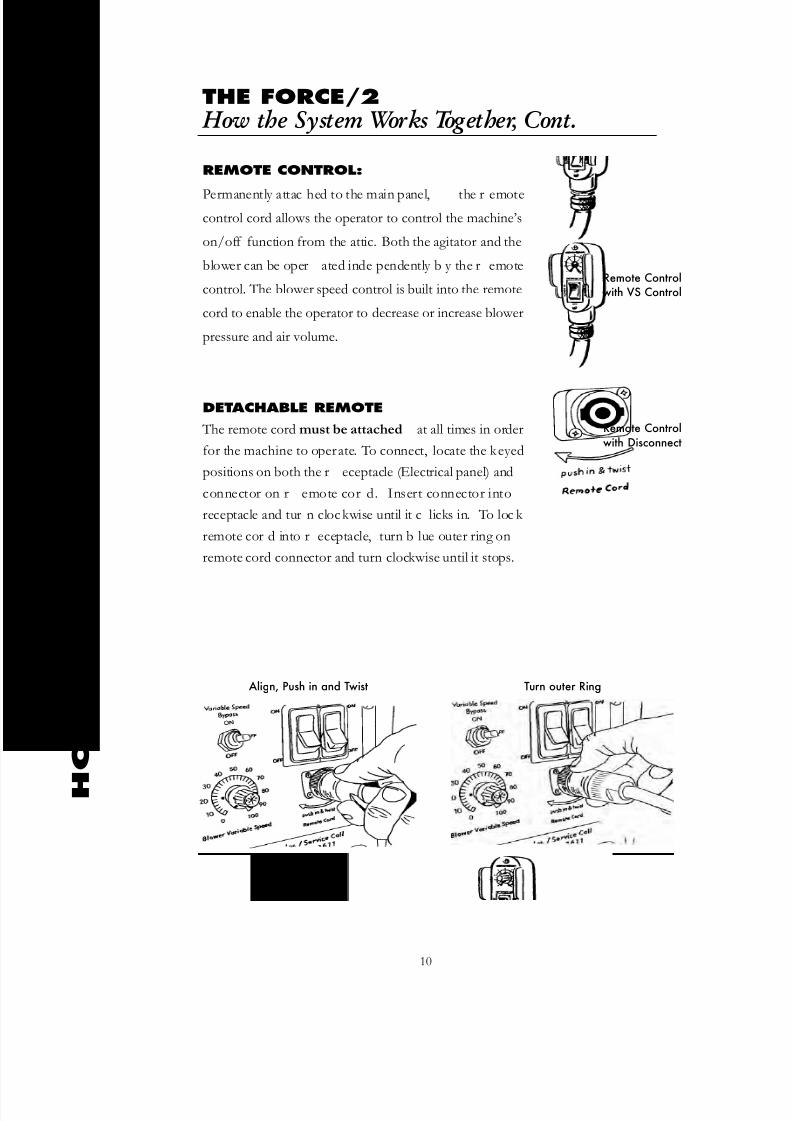
REMOTE CONTROL:
Permanently attac hed to the main panel, the r emotecontrol cord allows the operator to control the machine’s
on/off function from the attic. Both the agitator and the
blower can be oper ated inde pendently b y the r emote
control. The blower speed control is built into the remote
cord to enable the operator to decrease or increase blower
pressure and air volume.
DETACHABLE REMOTE
The remote cord must be attached at all times in order
for the machine to operate. To connect, locate the keyed
positions on both the r eceptacle (Electrical panel) and
connector on r emote cor d. Insert connector into
receptacle and tur n clockwise until it c licks in. To loc k
remote cor d into r eceptacle, turn b lue outer ring on
remote cord connector and turn clockwise until it stops.
H
O W
T H E S
Y S T E M W O R K S T O G
E T H E R
10
Remote Controlwith VS Control
Remote Controlwith Disconnect
Align, Push in and Twist Turn outer Ring

8/6/2019 F2 Manual Rev1 11
http://slidepdf.com/reader/full/f2-manual-rev1-11 13/60

8/6/2019 F2 Manual Rev1 11
http://slidepdf.com/reader/full/f2-manual-rev1-11 14/60
THE FORCE/2Set-Up and Operation
12
ELECTRICAL CONNECTIONS: Before connecting the mac hine to
electrical power, make sure all s witches are in the "off " position. Connect
both supplied extension cords to dedicated 115V 20 amp grounded outlets. In
the home, refrigerator or freezer outlets usually fit the amperage requirements.
If necessary, these a ppliances can be tempor arily unplug ged, enabling the
FORCE/2 to use the outlet. Disconnecting
these a ppliances for the shor t time needed to
operate the FOR CE/2 will not cause spoila ge.
Remember to r econnect an y unplug ged
appliance after the job is finished. If your jobrequires additional extension cords, make sure you use only a 10/3
cord for a 50 foot run or 8/3 cord for a 100 foot extension.
STARTING:
Operation fr om the Attic: To use the r emote control f eature for attic
operation, the s witches on the main electrical panel m ust be in the "on"
position. Control the machine using the rocker switch on the remote cord.
Operation fr om the Gr ound: To operate the FOR CE/2 from the
ground, the rocker switch on the remote control must be in the “on”position.
Operate the b lower and agita tor fr om the main electrical panel to ggle
switches. Note: In cold w eather, your machine is more dif ficult to star t. If
possible, store your FORCE/2 in a w arm area over-night before starting this
helps ensur e the lubricant (oil) is w arm,
enabling the bearings and g earbox to tur n
freely.
S E T - U P A N D O P E R
A T I O N

8/6/2019 F2 Manual Rev1 11
http://slidepdf.com/reader/full/f2-manual-rev1-11 15/60
THE FORCE/2Set-Up and Operation, Cont.
S E T - U P A N D O P E R
A T I O N
13
HOSE SETUP, ATTIC:
Cellulose: For normal attic applications, usea minimum of 100 f eet of 3 inc h hose on
your job. Longer hose length decr eases both
capacity and material throw. Using 200 feet of
hose, capacity and thr ow will be r educed by
approximately 30%. If you must use a hose
longer than 150 f eet, reduce the hose siz e to
2-1 ⁄ 2 inch diameter for the last 50'.
Fiber glass: Use a minimum of 150 feet of hose. Use 100 feet of 3" hose and a50 foot section of 2-1/2" hose using a 3 x 2-1/2" steel hose r educer. This hose
configuration aids in the opening of the fiber and incr eases the thr ow of the
material.
Example of Hose Connections:
HOPPER SAFETY : Your saf ety is the most impor tant consider ation
whenever you are using any mac hine. Following the instr uctions in this man ual
along with good common sense, should allow you to complete your job in a saf e
and efficient manner . First, before loading y our FOR CE/2, follow all safety
considerations provided by the manufacturer of the insulation material y ou are
using, including wearing protective masks or respirators. Never wear loose clothing
or other items while running this machine. Failure to follow safety precautions may
result in permanent injury.
Any time you overload the hopper or place objects other than
insulation material into the hopper , you ar e risking personal
injury or equipment br eakdown.

8/6/2019 F2 Manual Rev1 11
http://slidepdf.com/reader/full/f2-manual-rev1-11 16/60
THE FORCE/2Set-Up and Operation, Cont.
14
LOADING THE HOPPER: Machine may be “on or off ” while loading.
Cellulose, place the ba g of insulation material on the hopper . Use a knif e to
open the bag so that the material falls into the hopper. Your FORCE/2 is designed
to self-feed. Fiber glass, place the bag on the side of the hopper. Cut the bag in
thirds and dispense one third of the contents gradually until the agitator breaks up
and conditions the material. Load the remainder of the material according to the
distribution rate. Empty no more than 1 ⁄ 3 bag at a time into the hopper , waiting
until at least 1 ⁄ 4 of the material has been used bef ore adding additional insula tion.
For cing insulation material will cause overloading, electrical
failur e or possible machine damage.
If the agitator stops or the circuit breaker on the electrical panel trips, unplug the
machine from electrical power. Remove the cause of the jam from the hopper. You
may have to empty all the insula tion material to locate and remove the jam. After
clearing, reset the circuit breaker, reconnect power and continue normal operation.
See page 22 for more information on unjamming. S E T - U P A N D O P E R
A T I O N
Fiberglass Insulation Only: Cut as
shown and break bag into three sections
8/6/2019 F2 Manual Rev1 11
http://slidepdf.com/reader/full/f2-manual-rev1-11 17/60
THE FORCE/2Operational Guidelines
O P E R A T I O N A L G U I D
E L I N E S
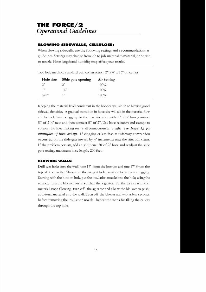
BLOWING SIDEWALLS, CELLULOSE:
When blowing sidewalls, use the following settings and r ecommendations asguidelines. Settings may change from job to job, material to material, or nozzle
to nozzle. Hose length and humidity may affect your results.
Two hole method, standard wall construction: 2" x 4" x 16" on center .
Hole size Slide gate opening Air Setting
2" 2" 100%
1" 11 ⁄ 2" 100%
5/8" 1" 100%
Keeping the material level consistent in the hopper will aid in ac hieving good
sidewall densities. A gradual transition in hose size will aid in the material flow
and help eliminate clogging. At the machine, start with 50' of 3" hose, connect
50' of 2-1 ⁄ 2" next and then connect 50' of 2". Use hose reducers and clamps to
connect the hose making sur e all connections ar e tight see page 13 for
examples of hose set-up. If clogging or less than sa tisfactory compaction
occurs, adjust the slide gate inward by 1 ⁄ 2" increments until the situation clears.
If the problem persists, add an additional 50' of 2" hose and readjust the slide
gate setting, maximum hose length, 200 feet.
BLOWING WALLS:
Drill two holes into the wall, one 17" from the bottom and one 17" fr om the
top of the cavity. Always use the lar gest hole possib le to pr event c logging.
Starting with the bottom hole, put the insulation nozzle into the hole, using the
remote, turn the blo wer on fir st, then the a gitator. Fill the ca vity until the
material stops f lowing, turn off the agita tor and allo w the blo wer to push
additional material into the wall. Turn off the blower and wait a few seconds
before removing the insula tion nozzle. Repeat the ste ps for filling the ca vity
through the top hole.
15

8/6/2019 F2 Manual Rev1 11
http://slidepdf.com/reader/full/f2-manual-rev1-11 18/60
Construction example: 2 inches x 4 inches x 8 feet on 16 inch centers, 2.8 cubic
foot cavity
CELLULOSE COVERAGE:
US Greenfiber Customer Support 800-228-0024
US Greenfiber, Cocoon 22.5lb bag
Wall Pack Density Pounds Per Cavity
2.6 PCF @ R13 7.07 lbs
FIBERGLASS COVERAGE:
JM Product Infor mation 800-654-3103
www.jm-builder .com/spider .php
Johns Manville Spider, 30lb bag
Wall Pack Density Pounds Per Cavity
1.0 PCF @ R13 2.72 lbs
1.8 PCF @ R15 4.89 lbs
_______________________________________________________________
CertainT eed Technical Services: (800) 233-8990
Certainteed, Optima 29.5lb bag
Wall Pack Density Pounds Per Cavity
1.0 PCF @ R14 2.72 lbs
1.8 PCF @ R15 4.89 lbs
These examples are guidelines only. Consult individual manufacturers
for specific information.
FIBERGLASS WET SPRAY COVERAGE
Guar dian Fiber glass Pr oduct infor mation: (800) 748-0035
Guardian UltraFit DS 30 pound bag
Wall Pack Density Pounds Per Cavity
2.5 PCF 6.8 lbs
Average yield per bag, 4-1/4 cavities per 30 pound bag
Use a minimum of 100' of hose for proper conditioning.
THE FORCE/2Sidewalls & Insulation Material
S I D E W A L L
& I N S U L A T I O N M A
T E R I A L
16

8/6/2019 F2 Manual Rev1 11
http://slidepdf.com/reader/full/f2-manual-rev1-11 19/60
THE FORCE/2Sidewalls & Insulation Material
17
S I D E W A L L
& I N S U L A T I O N M A
T E R I A L
FIGURING WALL CAVITY AREA
Measure wall cavity in inches. Multiply depth x width x height. Example:
(1)31 ⁄ 2" deep x 141 ⁄ 2" wide x 925 ⁄ 8" tall = 4,700 cubic inches
(2)Divide 4,700 by 1,728 = 2.72 cubic f eet in the cavity.
Each wall cavity may vary slightly.
(1,728 equals the number of cubic inches in a cubic foot.)
Actual pre-cut lumber dimensions:
2 x 4 x 8: 11 ⁄ 2 inches x 31 ⁄ 2 inches x 925 ⁄ 8 inches
2 x 6 x 8: 11 ⁄ 2 inches x 51 ⁄ 2 inches x 925 ⁄ 8 inches
CELLULOSE WET SPRAY
Your Force/2 can apply both w all-spray and spray-on materials. There are many
different types of material for these applications and depending upon the material
your results will differ. The Force/2 has been designed to apply most materials and
can recycle up 75/25 blend of Dry/Wet cellulose material. Using recycled material
will change the speed of the material traveling through the hose and will c hange
the impact (density) of the wall area being spr ayed. It is r ecommended that you
test a small ar ea of wall section to deter mine optimum machine settings bef ore
starting the job. Loading of the hopper can af fect the desired wall-spray job, werecommend that w hen loading the hopper do not dispense wet material
into an empty hopper! , doing so may clog hose! Dispense wet material on top
of dry material and allow the agitator to blend the materials. Hose length, nozzle
orifice size and design play a key role to a successful application. The nozzle you
select will deter mine ho w to set up the mac hine. General guideline for
setting your machine; 100 feet of 2 or 2-1/2" hose, variable speed setting of
80-100% with the slide g ate 1/4-1/3 open. When using 2 or 2-1/2" hose w e
recommend using an inser t tube to enhance setup and r educe the likely hood of
clogging the hose . For further information on Cellulose Wall-Spray or Spr ay-Onconsult Intec or your local supplier of insulation material.
8/6/2019 F2 Manual Rev1 11
http://slidepdf.com/reader/full/f2-manual-rev1-11 20/60
THE FORCE/2Generators and Extension Cords
G E N E R A T O R
S A N D E X
T E N S I O N
C O R D S
18
Your FORCE/2 will operate on power from a commercial-sized generator. No
household generators may be used due to the high inr ush requirements of theFORCE/2. Also, generators made by Honda, Y amaha, Coleman
and Generac ar e not r ecommended. While the y ar e of high quality,
these generators do not have the inrush protection devices necessary to start the
FORCE/2 and protect the generator. The start-up requirement for a FORCE/2
is 9660 watts; normal operating requirement is 3300 w atts. We r ecommend
a generator of not less than 9000 watts, 120 VAC. In addition, Intec
recommends generators that ha ve a 50% po wer boost f eature which aids the
generator in high current startups.
Running additional equipment from the same generator means you will need to
know the total electrical r equirements bef ore selecting the cor rect siz e of
generator. For details on selecting and pur chasing a g enerator, please call
INTEC.
Note: Using a generator of insufficient size will void your Warranty.
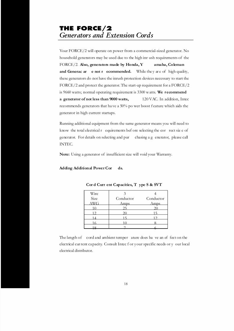
Adding Additional Power Cor ds.
WireSize
AWG1012141618
3Conductor
Amps252015107
4Conductor
Amps20151286
Cor d Curr ent Capacities, T ype S & SVT
The length of cord and ambient temper ature does ha ve an ef fect on the
electrical cur rent capacity. Consult Intec f or your specific needs or y our local
electrical distributor.

8/6/2019 F2 Manual Rev1 11
http://slidepdf.com/reader/full/f2-manual-rev1-11 21/60
THE FORCE/2 Maintenance
Reasonable pr eventive maintenance will help ensur e y our FOR CE/2 gi ves y ou
many years of satisfactory use. Cleaning the interior and exterior of your machineand protecting its finish with a product such as Armor All will keep it looking new.
CORDS AND SWITCHES
The remote cord and s witches are subject to consider able wear and tear during
normal use. Inspect all cords and switches each week for cuts or loose connections.
Repair or replace any damaged components at once to avoid possible injury.
AIRLOCK BLOW BACK
Airlock seals ar e the most impor tant component of keeping y our FOR CE/2
running in original condition. Airlock seals function m uch like the rings in a carengine, keeping pressure and air from esca ping. When a seal or pla te is damaged,
air from the blower will esca pe back into the hopper causing “b low back.” Blow
back will result in a considerable decrease in production.
Checking for blow back; unplug the machine from electrical power and empty all
insulation material from the hopper. Block the hose outlet with duct ta pe, or use
the palm of your hand. Reconnect the power and
turn on both the blower and agitator motor. A hissing or puffing sound of air
escaping into the hopper indicates blow back.
In addition, any insulation material remaining
in the airlock will blow back into the hopper,
creating dust. To remedy blow back, it is
necessary to replace the airlock seals or plates.
Note: Your FORCE/2 comes from the factory
preset to produce 3.2-4.8 PSI. You may purchase
a pressure gauge from Intec to aid in determining
the pressure developed by the blower and airlock, system.
M A I N T E N A N C E
19

8/6/2019 F2 Manual Rev1 11
http://slidepdf.com/reader/full/f2-manual-rev1-11 22/60
THE FORCE/2 Maintenance, Cont.
REPLACING AIRLOCK SEALS
We recommend changing the airloc k seals e very 300 hour s, 200,000 pounds of
insulation or once a year, whichever comes first.
Unplug the FOR CE/2 from electrical po wer and empty all insula tion material
from the hopper . Seal r eplacement r equires a 7/16" soc ket and r atchet, a 6"
socket extension and a 7/16" open-end wr ench. With the machine in an upright
position, locate the seven 1 ⁄ 4*20 bolts holding the seal in place. Loosen and remove
the fasteners. Remove the damaged seal from the rotor shaft. Reverse the process
to install a new seal. Be careful that the direction of the seal is correct. Seal must
be equally wrapped around both sides and seated all the w ay down on the rotor
shaft! Snug down the bolts. Do not overtighten. Overtightening will cause the
seal to bo w out a t the ends pr oducing uneven wear and pr emature f ailure. To
replace other dama ged seals, reconnect electrical po wer and, using the r emote
switch, move the air lock seal into the position f or r emoval. Again, disconnect
from electrical power before doing the actual r epair or r eplacement. Note: Do
not install the seals bac kwards. See pages 32 and 33 for additional
illustrations.
M A I N T E N A N C E
20

8/6/2019 F2 Manual Rev1 11
http://slidepdf.com/reader/full/f2-manual-rev1-11 23/60
GEARBOX
The oil in the gearbox of your FORCE/2 should be changed every year to ensureproper lubrication of the gears and seals.
Changing oil in all dir ect drive models:
Model 22015
Place the mac hine on its side with c lear access to the tw o
drain/fill plugs on the gearbox. Place a drain pan under each
plug to catch the used oil. Remove the drain plug from each
of the tw o g earbox c hambers with a 90º 3/8 inc h hex
wrench. Drain the oil into the pans . To refill, pour four
ounces of oil into a six ounce disposable paper cup . Bendcup lip to f orm a pouring spout. Pour a total of 20 ounces
into worm gear case and 16 ounces into bevel gear case, and reinstall plugs using the
hex wrench. Note: At cold temperatures, oil thickens, slowing the draining process.
Leave your machine in a w arm area overnight (eight hour s) to mak e oil changing
easier. See illustration for the location of the drain/fill plugs.
Recommended gearbox oil:
Model 22015 (Mfg from 7/89-11/02)
Reintroduced (12/06 to present)
Temperature 40° - 100° F Mobil SHC 634 g ear lube Temperatures -20° - +40° F Mobil 1 synthetic 5W-30
Worm gear case capacity 20 oz.
Bevel gear case capacity 16 oz.
Model 22014 Model 22014 (Mfg from 8/02-12/06)
Lay machine on its side with clear access to the bottom drain
plug. Place drain pan under dr ain plug and r emove using a
5/16 hex wrench. Drain oil into pan, tip machine upright to
drain remainder of oil in gearbox housing, close vent plug.
Pour 48 ounces into worm gear case and re-install drain plug. Tip machine on side and open v ent plug 1/4- 1/2 tur n by
hand. Note: In cold temper atures the oil thic kens slowing
the dr aining process . Leave the mac hine in a w arm area
overnight (eight hour s) to mak e oil c hanging easier . See
illustration for location of vent and drain plugs (page 22).
THE FORCE/2 Maintenance, Cont.
M A I N T E N A N C E
Model 22015
Model 22014
21
Model 22015
08/2002
8/6/2019 F2 Manual Rev1 11
http://slidepdf.com/reader/full/f2-manual-rev1-11 24/60
THE FORCE/2 Maintenance, Cont.
M A I N T E N A N C E
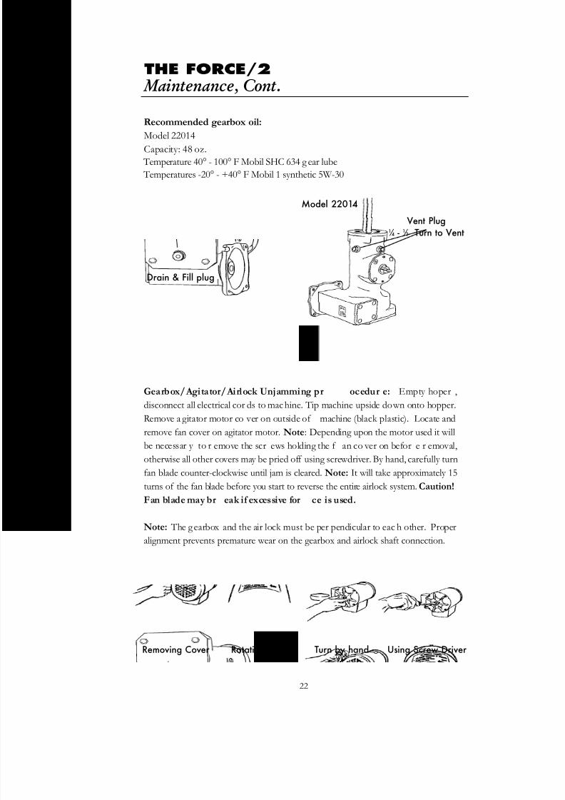
Recommended gearbox oil:
Model 22014Capacity: 48 oz.
Temperature 40° - 100° F Mobil SHC 634 g ear lube
Temperatures -20° - +40° F Mobil 1 synthetic 5W-30
Gearbox/Agitator/Airlock Unjamming pr ocedur e: Empty hoper ,
disconnect all electrical cor ds to machine. Tip machine upside down onto hopper.
Remove a gitator motor co ver on outside of machine (black plastic). Locate andremove fan cover on agitator motor. Note: Depending upon the motor used it will
be necessar y to r emove the scr ews holding the f an co ver on befor e r emoval,
otherwise all other covers may be pried off using screwdriver. By hand, carefully turn
fan blade counter-clockwise until jam is cleared. Note: It will take approximately 15
turns of the fan blade before you start to reverse the entire airlock system. Caution!
Fan blade may br eak if excessive for ce is used.
Note: The g earbox and the air lock must be per pendicular to eac h other. Proper
alignment prevents premature wear on the gearbox and airlock shaft connection.
Drain & Fill plug
Model 22014
Vent Plug1 ⁄ 4 - 1 ⁄ 2 Turn to Vent
22
Removing Cover Rotation Label Turn by hand Using Screw Driver

8/6/2019 F2 Manual Rev1 11
http://slidepdf.com/reader/full/f2-manual-rev1-11 25/60
THE FORCE/2 Maintenance, Cont.
BLOWER MAINTENANCE
Keeping the blo wer as c lean as possible will a void system o verheating.Overheating will cause lowered production, possible system failure and shorten
the e xpected lif e of your FOR CE/2. Inspect b lower br ushes e very thr ee
months or 100 hours of use. Replace brushes when they reach 1 ⁄ 4 inch or less in
length. Change the br ushes before the br ush stunt touc hes the comm utator.
When reassembling, the lead wires must be isolated from the motor frame and
any rotating parts. For optimum performance, new brushes must be properly
seated against the commutator before operating your FORCE/2 at full power.
NOTE: BRUSH INSTALLATION
After installation of new brushes, plug in machine as nor mal and set blo wer
speed control (variable speed) at 30% of full power, run for 1 ⁄ 2 hour. Set blower
speed control at 70% of full power, run for 1 ⁄ 2 hour.
CLEANING
Use compressed air to blow out motor and intake of blower every 20-30
hours of use to maximize blower impeller and motor life.
Blower W arranty Considerations. The following
blower abuse is not covered by warranty:
Damage in shipment
Visible moisture damage such as rust
Rust or other corrosion on motor exterior
Dirty motor or insulation buildup in impeller
Broken components, i.e. brushes, brush holder, etc.
User modification of blower, holes, etc.
User rewound armatures or fields
Evidence of user disassembly
Evidence of foreign object in fan end of motor
M A I N T E N A N C E
23

8/6/2019 F2 Manual Rev1 11
http://slidepdf.com/reader/full/f2-manual-rev1-11 26/60
REPLACING BLOWER BRUSHES
Model 21025 (105 CFM) brush replacement not recommended
Model 21024 (116 CFM) shown
Removing old brushes: Disconnect all
electrical cords to mac hine. Tip machine
upside do wn onto hopper . To facilita te
replacement of the blo wer br ushes
remove blower from machine. Locate
brush c lips (fig 1), using f lat
screwdriver place screwdriver under brush clip as shown (fig 2), pry in an upward
motion until loose . Remove brush clip and br ush assembly fr om motor housing
(fig 3). Remove wire connector from tab on brush assembly (fig 4).
Installing new brushes: Push wir e connector onto br ush ta b and ensure
connection is secure. Insert brush into housing with the tab and wire in the down
position. Slide brush assembly all the way into motor housing until it stops . Push
down and inward on brush assembly, slide brush clip into top of motor housing to
secure brush assembly (fig 5). When finished make sure the brush clip is f lush or
below motor housing (fig 6).
Note: Brush clip can only be installed one way. Do not for ce
brush clip into motor housing or damage may occur !
THE FORCE/2 Maintenance, Cont.
M A I N T E N A N C E
24
blower clip
fig 5 fig 6
fig 3
fig 4
fig 2fig 1

8/6/2019 F2 Manual Rev1 11
http://slidepdf.com/reader/full/f2-manual-rev1-11 27/60
THE FORCE/2Troubleshooting
Agitator does not Power cords Check cordoperate. not plugged in. and plug in.
Note: Agitator can Loose power cord/ Check condition of not be turned extension cord at electrical plug blades.by hand. electrical connection.
Electricity not present at Test extension cord withBlower plug. Transformer known good appliance.in machine not receiving If extension is not workingelectricity. check house electrical or
circuit breaker at house.
Rocker switch for agitator Flip rocker switch
is not in “on” position. “on” at main panel.
Circuit breaker tripped on Push to reset trippedmain panel. circuit breaker.
Jam in airlock exit tube. Disconnect electrical power.Remove hose from theexit tube. Locate jam andremove material with pliers.See gearbox section for additional info.
Jam between blade of Disconnect electrical power.agitator and airlock. Remove insulation material
Note: Jam may not from hopper. Locate jambe visible and remove material with
pliers. See gearbox sectionfor additional info.
Bearing on top of gearbox Have bearing replaced byworn or frozen (bearing a qualified service center.guides the agitator shaft).
Start-up capacitor blown Have capacitor replaced byon agitator motor. a qualified service center.
Remote rocker switch for Replace with originalagitator motor has failed. factory part.
Main panel rocker switch for Replace with originalagitator motor has failed. factory part.
Loose wire in electrical Have the system inspectedsystem. by a qualified service
center.
Agitator turns slow. Run capacitor in motor Have capacitor replacedworn out. by a qualified service
center.
T R O U B L E S H O
O T I N G
Problem Likely Cause Remedy
25

8/6/2019 F2 Manual Rev1 11
http://slidepdf.com/reader/full/f2-manual-rev1-11 28/60
THE FORCE/2Troubleshooting, Cont.
T R O U B L E S H O
O T I N G
Machine makes a Gearbox drive not Loosen gearbox andgrinding noise when engaged with airlock gearbox stabilizers. Alignrunning. rotor connection out gearbox and airlock shaft
of alignment. perpendicular to each other.Resecure bolts. Replacegearbox stabilizers if bent.
Low oil level in gearbox. Have the gearboxinspected and repaired by aqualified service center. Seegearbox section for oil capacity.
Agitator fan cover rubbing Remove black plastic cover against rotating fan blade. on outside of machine.
Remove agitator motor fancover and inspect fan bladeand bend cover back tonormal condition.
Decreased material Worn airlock seals. Inspect seals for tears or throw. cuts. See maintenance
section to replace or adjustas necessary.
Kink in hose. Run hose as straight aspossible to help maintainproduction.
Excess air leaking into Inspect seals for tears or hopper. cuts. See maintenance
section to replace or adjustas necessary.
Material buildup in Turn machine upside downblower housing. and use compressed air to
blow out air intake. Seediagram.
Machine does not run Remote cord not plugged Plug in remote cord intointo electrical panel electrical panel and position
the agitator and blower switch
to the on position.Blower power cord is not Check connection on power plugged in at main panel cord at main panel or or power cord does not make sure electricity ishave electrical power at present at power source.source.
No power. Check source of electricalpower. Possible trippedcircuit breaker.
Problem Likely Cause Remedy
26

8/6/2019 F2 Manual Rev1 11
http://slidepdf.com/reader/full/f2-manual-rev1-11 29/60
THE FORCE/2Troubleshooting Cont.
T R O U B L E S H O
O T I N G
Problem Likely Cause Remedy
27
Machine does not run Main panel circuit Wait for a few minutes,Cont. breaker tripped. push to reset.
Air, but no material, Slide gate closed. Open to operatingcomes out of hose position.
Bridging (air pocket Turn machine “off” andin hopper). disconnect from electrical
power. Redistribute materialin hopper. Reconnect toelectrical power.
Remote rocker switch for Replace with original
agitator motor has failed. factory part.
Circuit breaker tripped Push to reset.on main panel.
Jam between blade of Disconnect electrical power.agitator and airlock. Remove insulation material
from hopper. Locate jam andremove material with pliers.
Blower power cord is not Check connection on power plugged in at main panel cord at main panel or or power cord does not make sure electricity ishave electrical power at present at power
source. source.
Start up capacitor blown Have capacitor replaced byon agitator motor. a qualified service center.
Blower does not Variable speed bypass Position the variable speedoperate or variable switch is in the neutral bypass toggle switch to either speed does operate. position. the “on” or “o position. If
the switch is located inbetween the on/off text, it isin the neutral position and theblower will not operate.
Blower rocker switch on Switch rocker to “on”,usemain panel is “off”. remote box to operate.
Remote rocker switch for Replace with originalblower motor has failed. factory part.
Loose power cord/extension Check condition of cord at electrical system. electrical plug blades.

8/6/2019 F2 Manual Rev1 11
http://slidepdf.com/reader/full/f2-manual-rev1-11 30/60
THE FORCE/2Troubleshooting Cont.
T R O U B L E S H O
O T I N G
Blower does not Loose wire in electrical Have the system inspected
operate or variable system. and repaired by aspeed does operate. qualified service center.
Worn brushes in blower motor Have the brushes inspectedand replaced by aqualified service center.
Inline fuse blown. Turn machine upsidedown. Locate fuse holder on electrical box. Removeblown fuse and replacewith 15 amp AG style fuse.
Agitator trips circuit Low voltage 99-104v. FORCE/2 requires abreaker at main minimum of 20 ampspanel. @ 115V. Relocate power
cord to a dedicated 20amp circuit.
Incorrect size extension cord. For an additional 50' run,use 10/3 cord. For a 100'run use 8/3 cord.
Pushing down on material Do not push down onin hopper. insulation while filling hopper.
Wet insulation material in Do not use wethopper. material. Disconnect
electrical power andremove wet material.
Worn or frozen airlock Have bearing checked andbearing. replaced by a qualified
technician.
Blower trips circuit Low voltage. Blower requires a minimumbreaker at power of 20 amps @ 115V. Use asource. dedicated refrigerator outlet
or equivalent.
Incorrect extension cord. For an additional 50'run, use 10/3 cord. For a 100' run use 8/3 cord.
Operator in attic Static electricity from Mix half-and-half solutionkeeps getting insulation. of water and fabric softener.shocked. Mist into insulation while
loading hopper. Note:Excess moisture will causejamming.
Problem Likely Cause Remedy
28

8/6/2019 F2 Manual Rev1 11
http://slidepdf.com/reader/full/f2-manual-rev1-11 31/60
Fiber GlassDam
22141
Hopper 22000
Slide Gate Guide 22000-06 & 22000-07
Agitator 22025Slide Gate22000-03
Airlock Seal 22013
Airlock Rotor 22008without seals
3" Hose22051
Airlock Bearing22021
Gearbox22014/22015
Agitator Motor 21026/21026-S21027/21027-S
Blower 2102421025
Base22004
22004-01
Slide Gate Pin22000-04
THE FORCE/2 Mechanical Drawings
M E C H A N
I C A L D R A W I N G S
29
Airlock OutletPlate 3" 22005-01
Airlock StainlessInsert 3" 22005-03
Airlock Tube22005-09
Airlock Inlet Plate2 1 ⁄ 2" 22005-02
Airlock StainlessInsert 21 ⁄ 2" 22005-04

8/6/2019 F2 Manual Rev1 11
http://slidepdf.com/reader/full/f2-manual-rev1-11 32/60
M E C H A N
I C A L D R A W I N G S
(Mfg from 8/02-12/06)
1....21000-05-SELECTRICAL SYSTEM ASSM.2....21025-S ..BLOWER, 2 STG, 115V, 60 Hz,
105 CFM, ASSM.3....21024-S ..BLOWER, 2 STG, 115V, 60 Hz,116 CFM, ASSM.
4....21026-S ..AGITATOR MOTOR ASSM., 1.5 HP,115/22OV, 60Hz
4a..21027-S ..AGITATOR MOTOR ASSM., 2 HP,115/220V, 60 HZ
5....21026-16 AGITATOR MOTOR COVER ABS 1/4"6....21060-01 POWER CORD 100' 12/3 COMP,
TWIST LOCK7....22000 ....HOPPER, STD, BLUE8....22000-02 HOPPER BELLY BAND, STD9....22000-03 SLIDE GATE, F/2, STD10..22000-04 SLIDE GATE CABLE & PIN11 ..22000-06 SLIDE GATE GUIDE, RIGHT
12..22000-07 SLIDE GATE GUIDE, LEFT13..22004 ....BASE, STD, BLACK14..22001-01 BASE HOUSING LOUVER 3"15..22003-01 BASE PLATE, 1/4" x 28"16..22014 ....GEARBOX, F/217..22015-34 GEARBOX Stabilizer 18..22015-22 GEARBOX SUPPORT PLATE 4" x 4"19..22023-01 BLOWER COUPLING 8" LONG20..22025 ....AGITATOR, STD W/SET SCREWS21..22025-01 AGITATOR SNAP RING 1"22..22025-02 AGITATOR NEOPRENE PAD 1/4"23..22025-03 KEY 1/4" x 2-1/2"24..22025-05 AGITATOR MOTOR ROTATION LABEL
25..22042-01-SAIRLOCK ASSM. W/BEARINGS& SS INSERTS
26..22053-02 AGITATOR MOTOR SUPPORT BRACE
27..22131......AIRLOCK GASKET28..F101........3/8 x 16 x 2-1/4" CAPR. ZN29..F103 ......3/8 x 16 x 1-1/2" GIRD 2 ELEV. BOLT30..F104........3/8 x 16 x 1-3" GIRD 5 HEX ZN31..F107........3/8" SPLIT LOCK WASHER ZN32..F108 ......3/8" FLAT WASHER SAE33..F109 ......3/8 x 16 NYLON LOCK NUT ZN34..F112........1/4 x 20 x 7/8" GIRD 5 HEX ZN35..F114........1/4 x 20 NYLON LOCK NUT ZN36..F123........#6 x 3/4" SMS PP BLACK37..F130........3/16 x 11/16" ALUM. RIVET38..F142........# 8 x 32 x 1/2" PP, TYPE B, SELF TAP.39..F143........3/8 x 16 x 1" GIRD 5 HEX ZN40..F152........1/4 x 20 x 1/2" GIRD 2 ROLOCK
41..F159........1/4" FLAT WASHER SAE42..F162........CABLE CLAMP NYLON43..F223 ......# 10 x 32 x 5/8" PHILL TRUSS ZN44..F332 ......3/8 x 16 x 2" SOCKET FLAT
CAP SCREW45..F333 ......3/8 x 16 x 1-1/2" SOCKET
BUTTON SCREW46..22050-04 BLOWER CLAMP47..22026 ....BLOWER REDUCING RING48..F115 ....... .1/4" SPLIT LOCK WASHER, ZN49..F363 ......# 14 FLAT WASHER, ZN50..F199........M8 SPLIT LOCK WASHER, ZN51..F198........M8-1.25 x 25 HEX C/S METR. ZN
30

8/6/2019 F2 Manual Rev1 11
http://slidepdf.com/reader/full/f2-manual-rev1-11 33/60
M E C H A N
I C A L D R A W I N G S
25 ..22042-S....AIRLOCK ASSM. W/BEARINGS. STD26..22042-01-S AIRLOCK ASSM. W/BEARINGS
& SS INSERTS27 ..22053-01..AGITATOR MOTOR
SUPPORT BRACE28 ..22106 ......SERIAL TAG FORCE/229 ..22131 ......AIRLOCK GASKET30 ..F101 ........3/8*16 X 2-1/4" CARRIAGE ZN31 ..F103 ........3/8*16 X 1-1/2" GRD 2 ELEV. BOLT32 ..F104 ........3/8*16 X 1-3/4" GRD 5 HEX ZN33 ..F106 ........3/8*16 X 3/4" GRD 5 HEX ZN34 ..F107 ........3/8" SPLIT LOCK WASHER ZN35 ..F108 ........3/8" FLAT WASHER SAE36 ..F109 ........3/8*16 NYLON LOCK NUT ZN37 ..F112 ........1/4*20 X 7/8" GRD 5 HEX ZN38 ..F114 ........1/4*20" NYLON LOCK NUT ZN39 ..F123 ........#6 X 3/4" SMS PP BLACK40 ..F129 ........3/32" X 11/32" ALUM. RIVET41 ..F130 ........3/16" X 11/16" ALUM. RIVET42 ..F142 ........#8*32 X 1Z/2" PP, TYPE B, SELF TAP.43 ..F143 ........3/8*16 X 1" GRD 5 HEX ZN
44 ..F152 ........1/4*20 X 1/2" GRD 2 ROLOCK45 ..F159 ........1/4" FLAT WASHER NYLON46 ..F162 ........CABLE CLAMP NYLON47 ..F223 ........#10*32 X 5/8" PHILL TRUSS ZN
FLAT CAP SCREW48 ..F332 ........3/8*16 X 2" SOCKET49..F333 3/8*16 X 1-1/2"
SOCKET BUTTON SCREW50 ..22050-04..BLOWER CLAMP51 ..22026 ......BLOWER REDUCING RING
(Mfg from 7/89-11/02)Reintroduced (12/06 to present)
1 ....21000-S....ELECTRICAL SYSTEM ASSM.W/RS&VSC
2 ....21025-S ....BLOWER, 2 STG 115 V, 60HZ,105 CFM, ASSM.
3 ....21024-S ....BLOWER, 2 STG 115 V, 60HZ,116 CFM, ASSM.
4 ....21026-S....Agitator motor assm., 1.5 HP115/220V, 60 HZ
4A..21027-S ....Agitator motor assm., 2.0 HP115/220V, 60 HZ
5 ....21026-07 ..AGITATOR MOTOR COVER ABS 1/4"5a ..21026-17 ..AGITATOR MOTOR COVER 1/4" HC6 ....21060-01 ..POWER CORD 100' 12/3 COMP,
TWIST LOCK7 ....22000 ......HOPPER, STD, BLUE8 ....22000-02..HOPPER BELLY BAND, STD9 ....22000-03..SLIDE GATE, F/2, STD10 ..22000-04..SLIDE GATE CABLE & PIN11 ..22000-06..SLIDE GATE GUIDE, RIGHT12 ..22000-07..SLIDE GATE GUIDE, LEFT13 ..22004-01..BASE, STD, BLACK HC14..22001-01..BASE HOUSING LOUVER 3"
15 ..22003-01..BASE PLATE, 1/4" X 28"16 ..22015 ......GEARBOX, F/217 ..22015-21 ..GEARBOX STABILIZER18 ..22015-22..GEARBOX SUPPORT PLATE 4" X 4"19 ..22023-01..BLOWER COUPLING 8" LONG20..22025 ......AGITATOR, STD W/SET SCREWS21 ..22025-01 ..AGITATOR SNAP RING 1"22 ..22025-02..AGITATOR NEOPRENE PAD 1/4"23..22025-03..KEY 1/4" X 2-1/2"24 ..22025-05..AGITATOR MOTOR ROTATION LABEL
31

8/6/2019 F2 Manual Rev1 11
http://slidepdf.com/reader/full/f2-manual-rev1-11 34/60
M E C H A N
I C A L D R A W I N G S
32
Item # PART NUMBER DESCRIPTION1 ..........22005-02 ............AIRLOCK INLET PLATE ASSM. 2 1/2"
2 ..........22005-09 ............AIRLOCK TUBE 12" (CRS)
3 ..........22005-01 ............AIRLOCK OUTLET PLATE ASSM. 3"
4 ..........22021 ................AIRLOCK BEARING FLANGE 4 HOLE
5 ..........22008 ................AIRLOCK ROTOR ASSEMBLY W/O SEAL
6 ..........22013 ................AIRLOCK SEAL
7 ..........22116..................AIRLOCK WEAR WASHER
8 ..........F221....................CAGE NUT ZN
9 ..........F353 ..................3/8" INTERNAL LOCK WASHER ZN
10..........F108....................3/8" FLAT WASHER SAE
11..........F159....... .............1/4" SAE FLAT WASHER
12..........F114 ............... .....1/4*20 NYLON LOCKNUT ZN13..........F112 ............... .....1/4*20 x 7/8" GRADE 5 HEX HEAD ZN
14..........F110 ............... .....1/4*20 x 1 #9 HEX YELL. ZN
15..........F105....................3/8–24 x 7/8" GRADE 5 HEX HEAD ZN
16..........F115 ............... .....1/4" SPLIT LOCK WASHER ZN
17 ........22005-03 ............OUTLET SS INSERT 3"
18..........22005-04 ............INLET SS INSERT 2-1/2"
Airlock Assembly

8/6/2019 F2 Manual Rev1 11
http://slidepdf.com/reader/full/f2-manual-rev1-11 35/60
M E C H A N
I C A L D R A W I N G S
33
Item # PART NUMBER DESCRIPTION
1 ........22008 ..........AIRLOCK ROTOR ASSM. W/O SEALS
2 ........22013............AIRLOCK SEAL
3 ........22116............WEAR WASHER NYLON 5/8"
4 ........F112..............1/4*20x7/8 GRADE 5 HEX HEAD ZN
5 ........F114..............1/4*20 NYLON LOCKNUT ZN
Airlock Rotor

8/6/2019 F2 Manual Rev1 11
http://slidepdf.com/reader/full/f2-manual-rev1-11 36/60
M E C H A N
I C A L D R A W I N G S
34
Item # PART NUMBER DESCRIPTION
1 ........21025............BLOWER 2 STG., 115V, 60 Hz, 105 CFM
1 ........21024............BLOWER 2 STG., 115V, 60 Hz, 116 CFM
n/a ......21025-05 ......Blower Brush (set of two)
2 ........22022--..........BLOWER MOUNTING BRACKET
3 ........22022-01 ......BLOWER MOUNTING BRACKET 6-3/4"
4 ........F112..............1/4*20 X 7/8" GRADE 5 HEX, ZN
5 ........F114..............1/4" NYLON INSERT LOCKNUT, ZN
6 ........F146..............ELECTRICAL BOX FEMALE CONTACT
7 ........F159..............1/4" SAE FLAT WASHER
Model 21025
105 CFM Blower
Model 21024
116 CFM Blower

8/6/2019 F2 Manual Rev1 11
http://slidepdf.com/reader/full/f2-manual-rev1-11 37/60
E L E C T R
I C A L D R A W I N G S
35
Item # PART NUMBER DESCRIPTION
1 ........R22001-02 ....ELECTRICAL BOX W/HOLES
2 ........21012-00-S ....REMOTE CORD 18/7 x 100' COMP. W/RS & VSC
3 ........21016-S..........ELECTRICAL PANEL ASSM.
4 ........21002............TRANSFORMER 110 VOLT
5 ........21003-02 ......ELECTRICAL CONTACTOR (2 HP)
6 ........21003-03 ......ELECTRICAL CONTACTOR MOUNT RAIL
7 ........21017-02 ......FUSE HOLDER, BLOWER
8 ........21019............ELECTRICAL BOX FLANGE CONNECTOR
9 ........21020............ELECTRICAL BOX MOUNTING PLATE
10........21025-07 ......FUSE, 15 AMPS
11 ........21143-06 ......VARIABLE SPEED CONTROL
12........F120..............8*32 NYLON INSERT LOCK NUT13........F126..............8*32 X 1 4 PP ZN
14........F158..............#6 X 1/2" SMS PP ZN
15........F223..............10*32 X 5/8" PT ZN
16........F141..............8*32 X 1/2" PP ZN
Electrical without GFCI Mfgfrom 7/89 - 9/02

8/6/2019 F2 Manual Rev1 11
http://slidepdf.com/reader/full/f2-manual-rev1-11 38/60
E L E C T R
I C A L D R A W I N G S
Item # PART NUMBER DESCRIPTION
1 ........11072............REMOTE BOX TOGGLE SWITCH SEAL
2 ........21000-02-S ....ROCKER SWITCH, PANEL
3 ........21008-02 ......STRAIN RELIEF, ALUM. 1/2"
4 ........21010............ELECTRICAL FLANGE RECEPTACLE TWIST 15 AMP
5 ........21016-0 ........ELECTRICAL FACE PLATE “STD” 1996 W/SILK SCREEN
6 ........21045-01 ......CIRCUIT BREAKER 20 AMP
7 ........21045-02 ......CIRCUIT BREAKER BUTTON SEAL
8 ........21143-07........VARIABLE SPEED BYPASS SWITCH
9 ........F132..............STRAIN RELIEF LOCK NUT 1/2"
10........F119 ..............8*32 x 3/8" PP ZN
36
Electrical without GFCI Mfgfrom 7/89 - 9/02

8/6/2019 F2 Manual Rev1 11
http://slidepdf.com/reader/full/f2-manual-rev1-11 39/60
E L E C T R
I C A L D R A W I N G S
37
Item # PART NUMBER DESCRIPTION
1 ........21008-0 ........REMOTE BOX 3/4 W/HOLE
2 ........21008-09 ......STRAIN RELIEF, ALUMINUM, 3/4"
3 ........21008-10 ......REMOTE CORD 18/7 X 100' (ONLY)
4 ........21008-12 ......REMOTE BOX CONNECTOR SOCKET MALE
5 ........21008-13 ......REMOTE BOX CONNECTOR SOCKET FEMALE
6 ........21008-14 ......REMOTE BOX CONTACT PIN MALE
7 ........21008-15 ......REMOTE BOX CONTACT PIN FEMALE
8 ........21008-17 ......REMOTE BOX 3/4" SHIELD STICKER
9 ........21143-01........VARIABLE SPEED KNOB
10........21021-S ........REMOTE BOX ROCKER SWITCH ASSM.
11........21143-03-S ....VSC POT. ASSM.
12........RR21008-08 ..REMOTE BOX 3/4" SHIELD W/O STICKER
13........F119 ..............8*32 X 3/8 PP ZN
14........F122..............6*32 X 3/8 PP BLACK
15........F124..............6*32 NYLON INSERT LOCK NUT
16........F153..............#6 RING TERMINAL BLUE
Electrical without GFCI Mfgfrom 7/89 - 9/02
8/6/2019 F2 Manual Rev1 11
http://slidepdf.com/reader/full/f2-manual-rev1-11 40/60
E L E C T R
I C A L D R A W I N G S
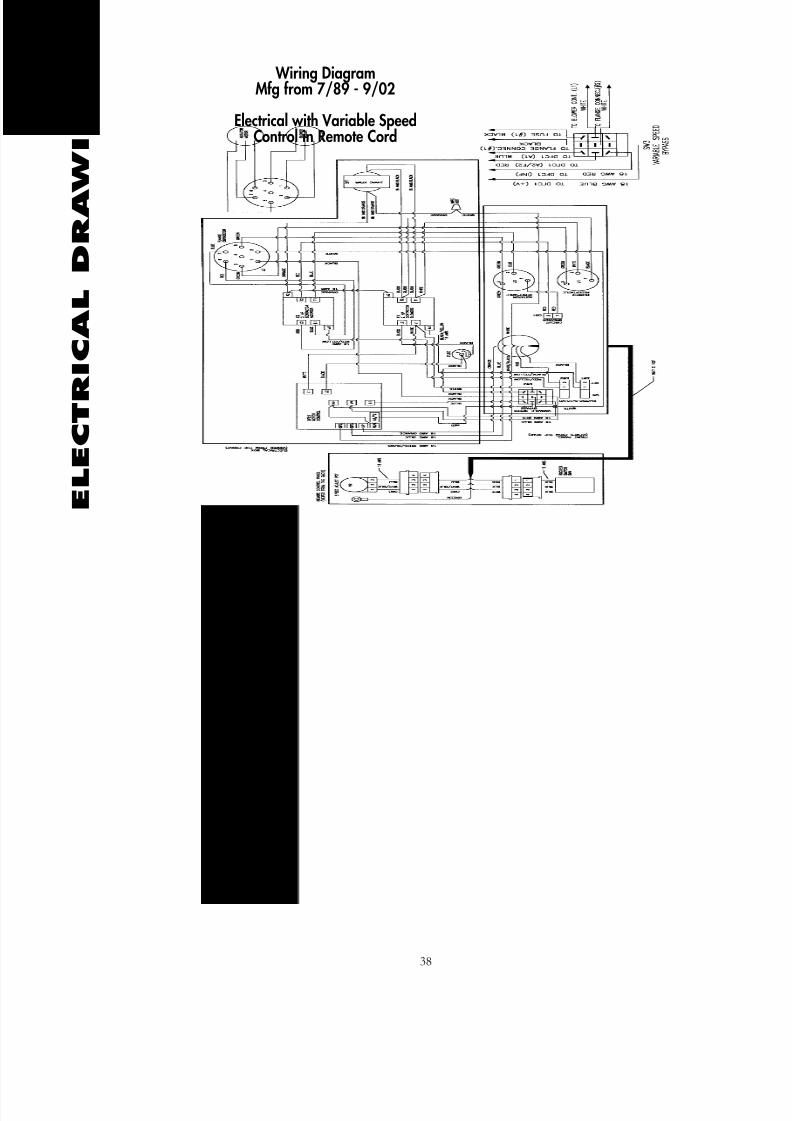
38
Wiring DiagramMfg from 7/89 - 9/02
Electrical with Variable SpeedControl in Remote Cord

8/6/2019 F2 Manual Rev1 11
http://slidepdf.com/reader/full/f2-manual-rev1-11 41/60
E L E C T R
I C A L D R A W I N G S
39
Item # PART NUMBER DESCRIPTION
1 ........R22001-02 ....ELECTRICAL BOX W/HOLES
2 ........21006-S ........REMOTE CORD 18/4 x 100' ASSM.
3 ........21016-02-S ....ELECTRICAL PANEL ASSM.
4 ........21002............TRANSFORMER 110 VOLT
5 ........21003-02 ......ELECTRICAL CONTACTOR (2 HP)
6 ........21003-03 ......ELECTRICAL CONTACTOR MOUNT RAIL
7 ........21017-02 ......FUSE HOLDER, BLOWER
8 ........21019............ELECTRICAL BOX FLANGE CONNECTOR
9 ........21020............ELECTRICAL BOX MOUNTING PLATE
10........21025-07 ......FUSE, 15 AMPS
11 ........F120..............8-32 NYLON INSERT LOCK NUT
12........F126..............8-32 X 1/4 PP ZN
13........F158..............6 X 1/2 SMS PP ZN
14........F223..............10-32 X 5/8" PP ZN
15........F1 41 ............8-32 X 1/2" PP ZN
Electrical with GFCIMfg from 8/02 - Present

8/6/2019 F2 Manual Rev1 11
http://slidepdf.com/reader/full/f2-manual-rev1-11 42/60
E L E C T R
I C A L D R A W I N G S
40
Item # PART NUMBER DESCRIPTION
12........F119 ..............8-32X3/8 PP ZN
13........F223..............10-32X5/8 FIL TRUSS ZN
14........21000-02 ......ROCKER SWITCH, PANEL
15........21008-02 ......STRAIN RELIEF, ALUM. 1/2"
16........21010 ............ELECTRICAL FLANGE RECEPTACLE, TWIST 15 AMP.34 17
21016-03 ..................ELECTRICAL FACE PLATE "OC" W/SILK SCREEN
18........21045-01 ......CIRCUIT BREAKER 20 AMP.
19........21045-02 ......CIRCUIT BREAKER BUTTON SEAL
20 ......01002............GROUND FAULT CIRCUIT, 20 AMP.21........F132..............STRAIN RELIEF LOCK NUT 1/2"
30 ......F124..............6-32 NYLON INSERT LOCK NUT
Electrical with GFCI
Mfg from 8/02 - Present

8/6/2019 F2 Manual Rev1 11
http://slidepdf.com/reader/full/f2-manual-rev1-11 43/60
E L E C T R
I C A L D R A W I N G S
41
Item # PART NUMBER DESCRIPTION
22 ......21008-0 ........REMOTE BOX 3/4" W/HOLE
23 ......21008-09 ......STRAIN RELIEF, ALUM. 3/4"
24........21008-03 ......REMOTE CORD 18/4X100' (ONLY)
25 ......01009............REMOTE BOX 31" SHIELD STICKER
26 ......RR21021-01....REMOTE BOX ROCKER SWITCH
26A ....11008-06-01-SREMOTE BOX ROCKER SWITCH ASSM.
27........RR21004........REMOTE BOX 3/4" SHIELD W/O STICKER
28 ......F119..............8-32X3/8 PP ZN
29 ......F122..............6-32X3/8 PP ZN
30 ......F124..............6-32 NYLON INSERT LOCK NUT
31........F153..............#6 RING TERMINAL, BLUE
32 ......F136..............BUTT SPLICE, BLUE
33 ......F230..............SHRINK TUBE 3/16X1/4", WHITE
34........F231..............SHRINK TUBE 3/16X1/4", RED
Electrical without GFCI Mfgfrom 7/89 - Present
Electrical with GFCI Mfgfrom 8/02 - Present
Remote Box Assembly

8/6/2019 F2 Manual Rev1 11
http://slidepdf.com/reader/full/f2-manual-rev1-11 44/60
E L E C T R
I C A L D R A W I N G S
42
Item # PART NUMBER DESCRIPTION
1 ........22001-03 ......ELECTRICAL BOX W/CURVE, WHOLES
2 ........21002............TRANSFORMER 110 VOLT
3 ........21003-02 ......ELECTRICAL CONTACTOR (2 HP)
4 ........21003-03 ......ELECTRICAL CONTACTOR MOUNT RAIL
5 ........21017-02 ......FUSE HOLDER, BLOWER
6 ........21019............ELECTRICAL BOX FLANGE CONNECTOR
7 ........21020-01 ......ELECTRICAL BOX MOUNTING PLATE 1/8 X 5 X 6-3/8
8 ........21025-07 ......FUSE, 15 AMPS
9 ........F120..............8-32 NYLON INSERT LOCK NUT
10........F126..............8-32 X 1/4 PP ZN
11........F158..............6 X 1/2 SMS PP ZN
12........F141..............B-32 X 1/2" PP ZN
Electrical with GFCIMfg from 8/02 - Present
VERSION A

8/6/2019 F2 Manual Rev1 11
http://slidepdf.com/reader/full/f2-manual-rev1-11 45/60
E L E C T R
I C A L D R A W I N G S
43
Item # PART NUMBER DESCRIPTION
1 ........R22001-02 ....ELECTRICAL BOX W/ HOLES
2 ........21002............TRANSFORMER 110 VOLT
3 ........21003-02 ......ELECTRICAL CONTACTOR (2 HP)
4 ........21003-03 ......ELECTRICAL CONTACTOR MOUNT RAIL
5 ........21017-02 ......FUSE HOLDER, BLOWER
6 ........21019............ELECTRICAL BOX FLANGE CONNECTOR
7 ........21020............ELECTRICAL BOX MOUNTING PLATE
8 ........21025-07 ......FUSE, 15 AMPS
9 ........F120..............8-32 NYLON INSERT LOCK NUT
10........F126..............8-32 X 1 4 PP ZN
11........F158..............6 X 1/2 SMS PP ZN
12........F141..............B-32 X 1/2" PP ZN
Electrical with GFCIMfg from 8/02 - Present
VERSION B

8/6/2019 F2 Manual Rev1 11
http://slidepdf.com/reader/full/f2-manual-rev1-11 46/60
E L E C T R
I C A L D R A W I N G S
44
Wiring DiagramManufactured from 8/02 - Present
Electrical with GFCI

8/6/2019 F2 Manual Rev1 11
http://slidepdf.com/reader/full/f2-manual-rev1-11 47/60

8/6/2019 F2 Manual Rev1 11
http://slidepdf.com/reader/full/f2-manual-rev1-11 48/60
E L E C T R
I C A L D R A W I N G S
46
Item # PART NUMBER DESCRIPTION
14........21003-02 ......ELECTRICAL CONTACTOR 2 HP
15........21003-03 ......ELECTRICAL CONTACTOR MOUNT RAIL
16........21143-06 ......VARIABLE SPEED CONTROL
17........21002......... ...TRANSFORMER 110/24 VAC
18........21020............ELECTRICAL BOX MOUNTING PLATE
19........R22001-02 ....ELECTRICAL BOX W/HOLES
20 ......21025-07 ......FUSE, 15 AMP
21........21017-02 ......FUSE HOLDER
22 ......21019............ELECTRICAL BOX FLANGE CONNECTOR
23 ......F119..............#-32x3/8" PP ZN
24........F120..............#8-32 NYLON INSERT LOCK NUT
25 ......F126..............#8-32x1/4" PP ZN
26 ......F158..............#6x1/2 SMS PP ZN
27........F223..............#10-32x5/8" PT ZN
28 ......F141..............#8-32x1/2" PP ZN
29 ......F190..............#4-40x1/4" PP MC
Electrical with Remote Disconnect Mfg from 9/02 - Present

8/6/2019 F2 Manual Rev1 11
http://slidepdf.com/reader/full/f2-manual-rev1-11 49/60
E L E C T R
I C A L D R A W I N G S
47
Wiring DiagramMfg from 9/02 - Present
Electrical With Remote Disconnect

8/6/2019 F2 Manual Rev1 11
http://slidepdf.com/reader/full/f2-manual-rev1-11 50/60

8/6/2019 F2 Manual Rev1 11
http://slidepdf.com/reader/full/f2-manual-rev1-11 51/60
FORCE/2
Electrical Drawings (Cont’d)
Electrical Wiring Diagram
with Variable speed control
and Remote disconnect
Mfg. from 1/2011 - Present

8/6/2019 F2 Manual Rev1 11
http://slidepdf.com/reader/full/f2-manual-rev1-11 52/60
EL ECTRI CA
L DRAWI NGS
FORCE/2
Electrical Drawings (Cont’d)

8/6/2019 F2 Manual Rev1 11
http://slidepdf.com/reader/full/f2-manual-rev1-11 53/60
8/6/2019 F2 Manual Rev1 11
http://slidepdf.com/reader/full/f2-manual-rev1-11 54/60
C
L A I M S , D A M A G E O R L O S S
THE FORCE/2Claims, Damage or Loss
48
These goods were carefully packed and thoroughly inspected bef ore leaving our
factory. Responsibility f or its saf e deli very w as assumed b y the car rier uponacceptance of the shipment. Inspect shipment carefully on the arrival for damage
to contents , shortages or equipment. In case of damage, save container and
packing material f or inspection. Claims for loss or damag e sustained in tr ansit
must, therefore, be made upon the carrier, as follows:
1. CONCEALED LOSS OR DAMAGE. Concealed loss or damage
means loss or damage which does not become apparent until the merchandise has
been unpacked. The contents may be damag ed in transit due to r ough handling
even though the car ton may not sho w e xternal dama ge. When the damag e is
discovered upon unpacking, make a written request for inspection by the carrier’s
agent within ten days of the delivery date. Then file a claim with the carrier since
such a claim is the car rier’s responsibility.
2. VISIBLE LOSS OR DAMAGE. Any external evidence of
loss or damage must be noted on the freight bill or the express receipt, and signed
by the carrier’s agent. Failure to adequately describe such external evidence of loss
or damage may result in the carrier refusing to honor a damage claim. The form
required to file such a claim will be supplied by the carrier.
3. SHOR TAGE. If the number of containers in the shipment does not
correspond with the transportation bill, obtain carrier's notation of shortage and
signature on transportation bill. When the number of containers is cor rect, but
there is indica tion of pilferage, notify carrier in writing with a complete list of
missing merchandise.

8/6/2019 F2 Manual Rev1 11
http://slidepdf.com/reader/full/f2-manual-rev1-11 55/60
THE FORCE/2Claims, Damage or Loss
C
L A I M S , D A M A G E O R L O S S
49
Claims for loss or damage must be filed with the carrier by the consignee within
24 hours after r eceipt of goods. We will assist you in every possible manner
but cannot be responsible for the collection of a claim or the cost of replacement
of the damaged goods.
If you have any questions r egarding the abo ve infor mation please f eel free to
contact an INTEC representative.
RETURNS
We at INTEC sincerely hope the merchandise you have just received is in excellent
condition and satisfies your expectations. If not, please look below and follow the
instructions which apply to your particular situation.
MERCHANDISE IS DAMAGED.
If the carrier is UPS:
Keep the merchandise in the original packing materials and carton.
Cal l UPS at (800) 742-5877 or contact them using their w eb address:
www.ups.com/using/custserv/ to notify them of the damaged package.
Fill out the inf ormation sheet on the f ollowing page and mail or fax it to the
attention of the Shipping Department.
Upon retur n of this for m and/or the damag ed mer chandise, we will send areplacement or credit your account.
Other than UPS:
Keep the merchandise in the original packing materials and carton.
Call the Shipping De partment a t the n umber on the f ollowing page for fur ther
instructions.
Upon return of this form and/or the damaged merchandise by the carrier, we will
send you a r eplacement or cr edit your account. Do not retur n any merchandise
through the U.S. Post Office.
MERCHANDISE IS PERSONALLY UNSATISFACTORY TO YOU.
You may return the merchandise, along with a RMA number on outside of carton
and a copy of your invoice to the Shipping De partment at the address provided
on the next pa ge. Upon its r eturn intact, we will send a r efund or cr edit y our
account. A restocking fee may be charged.

8/6/2019 F2 Manual Rev1 11
http://slidepdf.com/reader/full/f2-manual-rev1-11 56/60
THE FORCE/2Returns
SHIPMENTS TO FACTORY
All shipments to the factory must have a RMA number on the outside of the carton. You
will be given a RMA number when you contact the Sales De partment. The RMA is the
only way to tr ack and assur e that y our request is handled pr operly. If you received an
invoice with y our merchandise, please include a cop y of the invoice with all r eturned
materials.
Company Name________________________________________
Contact Name ________________________________________
Phone________________________ Fax ____________________
Address ______________________________________________
City_____________________ State____ Zip ____________________
Comments ____________________________________________
__________________________________________________________________________________________________________________________________________________________________________________________________________________________
__________________________________________________________________________________________________________________________________________________________________________________________________________________________
Invoice Number_______________ RMA Number ____________
Shipping Department Ph: 1-303-833-6644
INTEC 1-800-666-1611
3771 Monarch Street Fax: 1-303-833-6650
Frederick, CO 80530 E-mail: [email protected]
R E
T U R N S
50

8/6/2019 F2 Manual Rev1 11
http://slidepdf.com/reader/full/f2-manual-rev1-11 57/60
THE FORCE/2Receiving Replacement Parts
51
R E C E I V
I N G R E P L
A C E M E N T
P A R T S
When y ou call INTEC , please ha ve a vailable the model n umber and serial
number of your machine, as w ell as description of the def ective par t or an
explanation of the defect.
We will issue a R eturn Merchandise A uthorization (RMA) n umber and
instructions to return the defective part. All shipments to INTEC must be sent
via UPS , except in the case of complete mac hines, when a common car rier
should be used. The warranty on your machine does not cover fr eight or labor
char ges . All shipments to the factory or service center must be freight prepaid.
No freight collect shipments will be accepted without prior approval.
Your RMA number must appear on the outside of any r etur ned
cartons. W e assume no r esponsibility for incoming lost or
untraceable shipments. RMA numbers expir e 30 days after issue
date. Shipments beyond the 30-day expiration may not be
cr edited.
We will repair or replace, at our option, any returned part found to be def ective
in materials or workmanship under the ter ms of our limited warranty. Repaired
or replaced parts will be returned to you freight collect.
If we deter mine the par t f ailure w as due to misuse , alteration, negligence,
accident or operating beyond rated capacity, we will contact you. At your option,
we will send you a new part at the prevailing price or return the failed part to you.
All shipments from the factory are sent freight collect.
If you require a replacement part prior to a w arranty decision, we will send the
part to y ou at the pr evailing price, under your current terms. When we receive
the defective part and a w arranty decision has been made , INTEC will either
issue a credit to your account or return the failed part to you.
Shipping Department Ph: 1-303-833-6644
INTEC 1-800-666-1611
3771 Monarch Street Fax: 1-303-833-6650
Frederick, CO 80530 E-mail: [email protected]

8/6/2019 F2 Manual Rev1 11
http://slidepdf.com/reader/full/f2-manual-rev1-11 58/60
THE FORCE/2Warranty
W A R R A N T Y
It is e xpressly under stood and a greed that no officer , agent, salesman or emplo yee
of the Manufacturer INTEC has the authority to ob ligate the Manufacturer by any terms, stipula-
tions, or conditions not her ein expressed; that all previous representations and agreements, either verbal or written, referring to the machinery and equipment, which is the subject of this Warranty,
are hereby superseded and canceled, and that there are no promises or agreements outside of this
Warranty ag reement. Furthermore, the manufacturer hereby disclaims any implied w arranties of
merchantability, or implied warranties of fitness for a particular purpose.
With the above understanding, the Manufacturer's FORCE/2 insulation blowing machine is sold
with the following one (1) year Limited Warranty, and no other:
a) Manufacturer warrants to the original purchaser that the machine is well made, of good material
and durable; but only if the machine is operated and maintained in accordance with this Operator's
Manual and the Maintenance Manual. This Warranty is void if the machine is not so operated andmaintained, or if the machine is used for blowing materials other than those which are intended to
be used with the machine.
b) Manufacturer guarantees the mac hine to be fr ee from manufacturing defects a t the time of
shipment, and to remain fr ee from defects when operated under nor mal use, for a period of one
(1) year from the date of factory shipment, with the exception of the blower, electrical and airlock
components, which are guaranteed for a period of ninety (90) days from date of factory shipment.
c) This Warranty shall not a pply to any mac hine or component par t which, in the opinion of the
Manufacturer, has been altered, subject to misuse, negligence, accident or operated beyond factory
rated capacity. All requested Warranty work shall be performed at Manufacturer's factory or by an
Authorized Factory Ser vice Facility. Failure to ha ve the Warranty work done at Man ufacturer’s
factory or by an Authorized Factory Service Facility will void this Warranty. Manufacturer will bear
full responsibility to repair or re place, at its option, without charge to the original pur chaser, any
part which, in the Manufacturer's opinion, is found to be defective.
d) All par ts c laimed def ective b y original pur chaser shall be r eturned, properly
identified, to Manufacturer's f actory or A uthorized Factory Ser vice f acility, freight pr epaid. All
replacement, repaired or non-def ective par ts will be r eturned to pur chaser, freight collect.
Manufacturer will suppl y replacement parts prior to r eceipt of any par ts claimed defective, only
with the under standing that suc h re placement par ts will be shipped to pur chaser at the then
prevailing price of said part, C.O.D., freight collect. Manufacturer will reimburse cost of any such
part only after receipt and inspection, and finding said part defective.
e) Manufacturer's liability is e xpressly limited to the r epair or re placement of defective parts set
forth in this Warranty. All other damages and warranties, statutory or otherwise, being waived by
original purc haser as a condition of sale and purc hase of said mac hines. Furthermore, the
Manufacturer shall not be lia ble f or dama ges or dela ys caused b y def ective material or
workmanship.
This Warranty applies only to the original purchaser and is not transferable.
52

8/6/2019 F2 Manual Rev1 11
http://slidepdf.com/reader/full/f2-manual-rev1-11 59/60
THE FORCE/2 Insulation Terms and Values
R-VALUE: The resistance (R) to heat or cold. The higher the R Value, the
greater the resistance and the better the insulation factor.
SETTLEMENT: All b lown insulation will settle after installa tion. Your
FORCE/2 installs near settled density . Consult the chart on the material bag
for coverage and install accordingly.
COVERAGE: Every bag of material comes with a coverage chart
detailing R-Value ratings. Average ratings for various materials are:
Cellulose: R = 3.7 per inc h
Rockwool: R = 2.6 per inch
Fiberglass: R = 2.2 per inch
CFM: Blowers are measured by Cubic Feet per Minute. A low CFM blower
reduces “dust” when blowing insulation into an attic. The FORCE/2 features
the lowest CFM of all insulation b lowing machines, minimizing the “dust”
problem. You’ll be able to see what you are doing.
PSI: Blowers are also rated by Pounds of pressure per Square Inch. A high
PSI does a better job of blowing insulation. Your FORCE/2 produces 3.2-4.0
PSI which is the best for blowing insulation.
BRIDGING: A pocket of air, or void, created by improper agitation in the
hopper. A “bridg e” can stop production until c leared. Your FOR CE/2 is
designed with a non-bridging hopper . However, you ma y e xperience a
temporary bridge while using your machine. Waiting a few seconds will most
likely clear a temporary bridge. If not, unplug your machine and redistribute
the material in the hopper.
VENTILATION: Proper air f low r equires one squar e f oot of air
movement for every 150 square feet of attic area.
AIRLOCK SEAL: Also known as flapper, rubbers, paddles.
I N S U L A
T I O N T E R
M S A N D V
A L U E S
53

8/6/2019 F2 Manual Rev1 11
http://slidepdf.com/reader/full/f2-manual-rev1-11 60/60
THE FORCE/2 Insulation Terms and Values, Cont.
COMMON INSULATION VALUES
Material Thickness R-Value
Air Space 1" 1.01
Cellulose loose fill 1" 3.70
Celotex 1" 3.03
Concrete block 8", hollow 1.11
Fiberglass batt 31 ⁄ 2" 11.0
Fiberglass batt 8" 19.0
Fiberglass loose fill 1" 2.2
Rockwool batt 3 ⁄ 4" 11.0
Rockwool batt 6 - 71 ⁄ 2" 22.0
Rockwool loose fill 1" 2.60
Plywood 1 ⁄ 2" .62
Polyurethane board 1" 6.25
Vermiculite 1" 2.13
I N S U L A
T I O N T E R
M S A N D V
A L U E S