fa integrated tool package cx-one cx-programmer ver€¦ · fa integrated tool package cx-one ... 5...
TRANSCRIPT
CSM_CX-Programmer_Ver8_DS_E_1_1
1
FA Integrated Tool Package CX-One
CX-Programmer Ver.8Improve Productivity for SYSMAC PLCs from Ladder Program Development and Unit Setup to Debugging and Maintenance
• Application software to create and debug programs for SYSMAC CS/CJ/CP/NSJ-series, C-series, and CVM1/C-series CPU Units.
Features• Easily Achieve Position Control with Wading Through User Manuals.• Complete Support for Synchronous Operation between Units.• Easier Connection to PLCs.• Batch Backup/Restore with a Computer.• Comprehensive Programming Environment.• High Program Readability.• Time Required for Onsite Startup and Debugging Has Been Significantly Reduced.
CX-Programmer Ver.8
2
Ordering Information• International Standards• The standards are abbreviated as follows: U: UL, U1: UL (Class I Division 2 Products for Hazardous Locations), C: CSA, UC: cULus, UC1: cULus (Class I Division
2 Products for Hazardous Locations), CU: cUL, N: NK, L: Lloyd, and CE: EC Directives.• Contact your OMRON representative for further details and applicable conditions for these standards.
Support Software
*1. Multi licenses are available for the CX-One (3, 10, 30, or 50 licenses).*2. When purchasing the DVD format, verify the computer model and DVD drive specifications before purchasing.
Support Software (Micro PLC Edition)
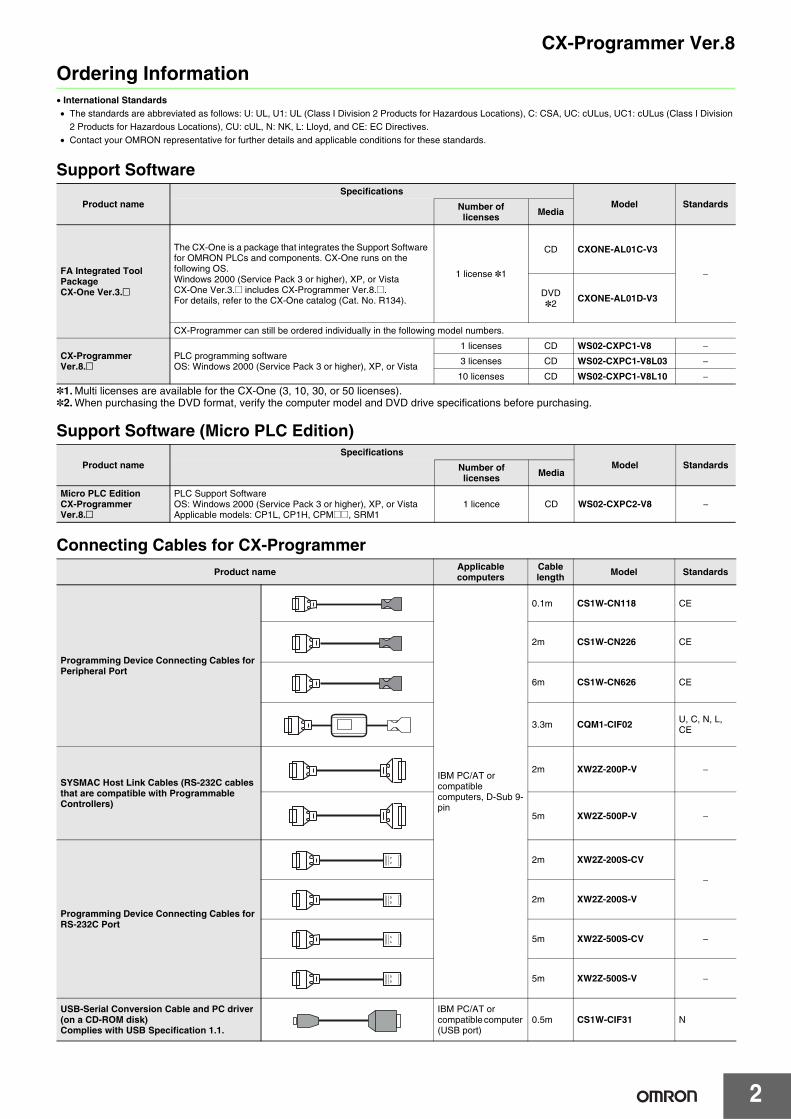
Connecting Cables for CX-Programmer
Product nameSpecifications
Model StandardsNumber oflicenses Media
FA Integrated Tool Package CX-One Ver.3.@
The CX-One is a package that integrates the Support Software for OMRON PLCs and components. CX-One runs on the following OS.Windows 2000 (Service Pack 3 or higher), XP, or VistaCX-One Ver.3.@ includes CX-Programmer [email protected] details, refer to the CX-One catalog (Cat. No. R134).
1 license *1
CD CXONE-AL01C-V3
−
DVD*2 CXONE-AL01D-V3
CX-Programmer can still be ordered individually in the following model numbers.
CX-Programmer Ver.8.@
PLC programming softwareOS: Windows 2000 (Service Pack 3 or higher), XP, or Vista
1 licenses CD WS02-CXPC1-V8 −
3 licenses CD WS02-CXPC1-V8L03 −
10 licenses CD WS02-CXPC1-V8L10 −
Product nameSpecifications
Model StandardsNumber oflicenses Media
Micro PLC EditionCX-Programmer Ver.8.@
PLC Support SoftwareOS: Windows 2000 (Service Pack 3 or higher), XP, or VistaApplicable models: CP1L, CP1H, CPM@@, SRM1
1 licence CD WS02-CXPC2-V8 −
Product name Applicable computers
Cable length Model Standards
Programming Device Connecting Cables for Peripheral Port
IBM PC/AT or compatible computers, D-Sub 9-pin
0.1m CS1W-CN118 CE
2m CS1W-CN226 CE
6m CS1W-CN626 CE
3.3m CQM1-CIF02 U, C, N, L, CE
SYSMAC Host Link Cables (RS-232C cables that are compatible with Programmable Controllers)
2m XW2Z-200P-V −
5m XW2Z-500P-V −
Programming Device Connecting Cables for RS-232C Port
2m XW2Z-200S-CV
−
2m XW2Z-200S-V
5m XW2Z-500S-CV −
5m XW2Z-500S-V −
USB-Serial Conversion Cable and PC driver (on a CD-ROM disk) Complies with USB Specification 1.1.
IBM PC/AT or compatible computer (USB port)
0.5m CS1W-CIF31 N
CX-Programmer Ver.8
3
Note: For information on confirmations of the CX-Programmer, Connecting Cables, and PLCs, refer to Applicable Peripheral Devices in this datasheet.
Product ConfigurationSetup disk : (CD) CD 1 piece in the caseGuidance : A4 size, English/JapaneseUser license agreement/User registration card, English/Japanese
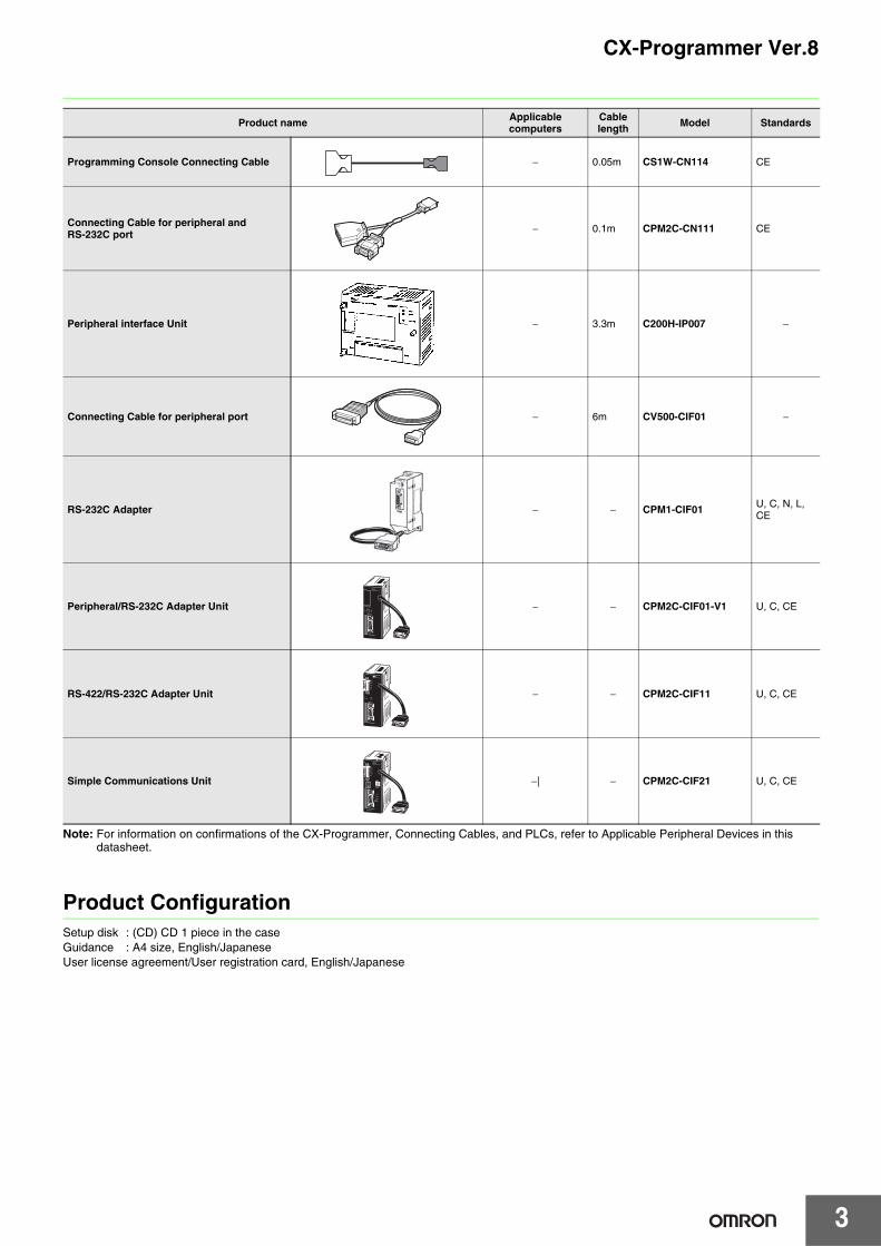
Programming Console Connecting Cable − 0.05m CS1W-CN114 CE
Connecting Cable for peripheral and RS-232C port − 0.1m CPM2C-CN111 CE
Peripheral interface Unit − 3.3m C200H-IP007 −
Connecting Cable for peripheral port − 6m CV500-CIF01 −
RS-232C Adapter − − CPM1-CIF01 U, C, N, L, CE
Peripheral/RS-232C Adapter Unit − − CPM2C-CIF01-V1 U, C, CE
RS-422/RS-232C Adapter Unit − − CPM2C-CIF11 U, C, CE
Simple Communications Unit −| − CPM2C-CIF21 U, C, CE
Product name Applicable computers
Cable length Model Standards
CX-Programmer Ver.8
4
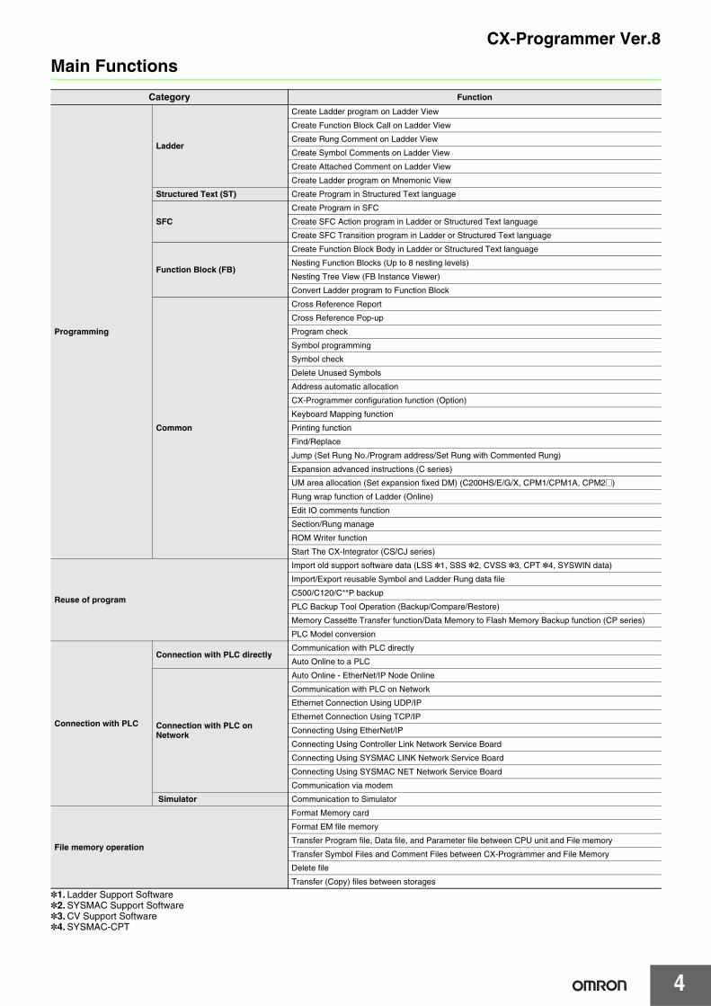
Main Functions
*1. Ladder Support Software*2. SYSMAC Support Software*3. CV Support Software*4. SYSMAC-CPT
Category Function
Programming
Ladder
Create Ladder program on Ladder View
Create Function Block Call on Ladder View
Create Rung Comment on Ladder View
Create Symbol Comments on Ladder View
Create Attached Comment on Ladder View
Create Ladder program on Mnemonic View
Structured Text (ST) Create Program in Structured Text language
SFC
Create Program in SFC
Create SFC Action program in Ladder or Structured Text language
Create SFC Transition program in Ladder or Structured Text language
Function Block (FB)
Create Function Block Body in Ladder or Structured Text language
Nesting Function Blocks (Up to 8 nesting levels)
Nesting Tree View (FB Instance Viewer)
Convert Ladder program to Function Block
Common
Cross Reference Report
Cross Reference Pop-up
Program check
Symbol programming
Symbol check
Delete Unused Symbols
Address automatic allocation
CX-Programmer configuration function (Option)
Keyboard Mapping function
Printing function
Find/Replace
Jump (Set Rung No./Program address/Set Rung with Commented Rung)
Expansion advanced instructions (C series)
UM area allocation (Set expansion fixed DM) (C200HS/E/G/X, CPM1/CPM1A, CPM2@)
Rung wrap function of Ladder (Online)
Edit IO comments function
Section/Rung manage
ROM Writer function
Start The CX-Integrator (CS/CJ series)
Reuse of program
Import old support software data (LSS *1, SSS *2, CVSS *3, CPT *4, SYSWIN data)
Import/Export reusable Symbol and Ladder Rung data file
C500/C120/C**P backup
PLC Backup Tool Operation (Backup/Compare/Restore)
Memory Cassette Transfer function/Data Memory to Flash Memory Backup function (CP series)
PLC Model conversion
Connection with PLC
Connection with PLC directlyCommunication with PLC directly
Auto Online to a PLC
Connection with PLC on Network
Auto Online - EtherNet/IP Node Online
Communication with PLC on Network
Ethernet Connection Using UDP/IP
Ethernet Connection Using TCP/IP
Connecting Using EtherNet/IP
Connecting Using Controller Link Network Service Board
Connecting Using SYSMAC LINK Network Service Board
Connecting Using SYSMAC NET Network Service Board
Communication via modem
Simulator Communication to Simulator
File memory operation
Format Memory card
Format EM file memory
Transfer Program file, Data file, and Parameter file between CPU unit and File memory
Transfer Symbol Files and Comment Files between CX-Programmer and File Memory
Delete file
Transfer (Copy) files between storages
5
CX-Programmer Ver.8
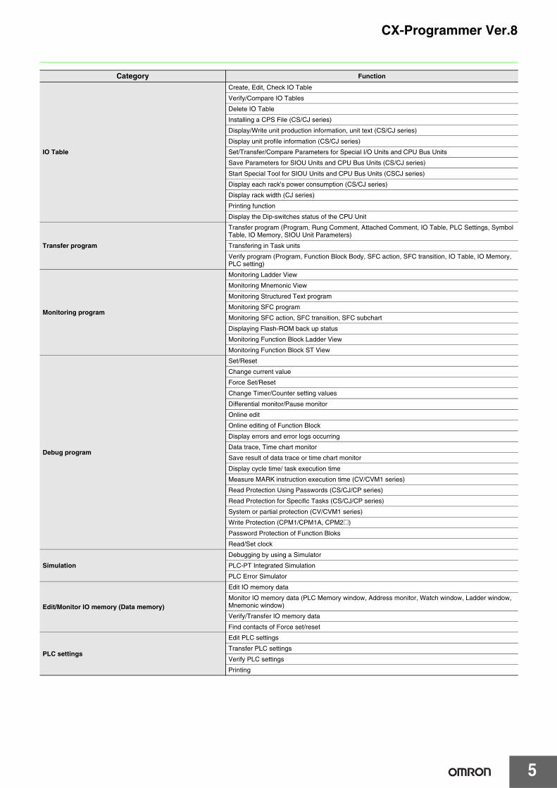
Category Function
IO Table
Create, Edit, Check IO Table
Verify/Compare IO Tables
Delete IO Table
Installing a CPS File (CS/CJ series)
Display/Write unit production information, unit text (CS/CJ series)
Display unit profile information (CS/CJ series)
Set/Transfer/Compare Parameters for Special I/O Units and CPU Bus Units
Save Parameters for SIOU Units and CPU Bus Units (CS/CJ series)
Start Special Tool for SIOU Units and CPU Bus Units (CSCJ series)
Display each rack's power consumption (CS/CJ series)
Display rack width (CJ series)
Printing function
Display the Dip-switches status of the CPU Unit
Transfer program
Transfer program (Program, Rung Comment, Attached Comment, IO Table, PLC Settings, Symbol Table, IO Memory, SIOU Unit Parameters)
Transfering in Task units
Verify program (Program, Function Block Body, SFC action, SFC transition, IO Table, IO Memory, PLC setting)
Monitoring program
Monitoring Ladder View
Monitoring Mnemonic View
Monitoring Structured Text program
Monitoring SFC program
Monitoring SFC action, SFC transition, SFC subchart
Displaying Flash-ROM back up status
Monitoring Function Block Ladder View
Monitoring Function Block ST View
Debug program
Set/Reset
Change current value
Force Set/Reset
Change Timer/Counter setting values
Differential monitor/Pause monitor
Online edit
Online editing of Function Block
Display errors and error logs occurring
Data trace, Time chart monitor
Save result of data trace or time chart monitor
Display cycle time/ task execution time
Measure MARK instruction execution time (CV/CVM1 series)
Read Protection Using Passwords (CS/CJ/CP series)
Read Protection for Specific Tasks (CS/CJ/CP series)
System or partial protection (CV/CVM1 series)
Write Protection (CPM1/CPM1A, CPM2@)
Password Protection of Function Bloks
Read/Set clock
Simulation
Debugging by using a Simulator
PLC-PT Integrated Simulation
PLC Error Simulator
Edit/Monitor IO memory (Data memory)
Edit IO memory data
Monitor IO memory data (PLC Memory window, Address monitor, Watch window, Ladder window, Mnemonic window)
Verify/Transfer IO memory data
Find contacts of Force set/reset
PLC settings
Edit PLC settings
Transfer PLC settings
Verify PLC settings
Printing
6
CX-Programmer Ver.8
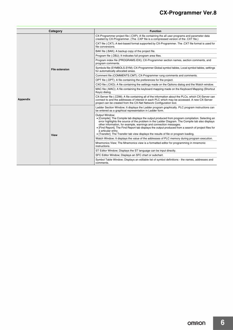
Appendix
File extension
CX-Programmer project file (.CXP); A file containing the all user programs and parameter data created by CX-Programmer. (The .CXP file is a compressed version of the .CXT file.)
CXT file (.CXT); A text-based format supported by CX-Programmer. The .CXT file format is used for file conversions.
BAK file (.BAK); A backup copy of the project file.
Program file (.OBJ); It indicates full program area files.
Program index file (PROGRAMS.IDX); CX-Programmer section names, section comments, and program comments.
Symbols file (SYMBOLS.SYM); CX-Programmer Global symbol tables, Local symbol tables, settings for automatically allocated areas.
Comment file (COMMENTS.CMT); CX-Programmer rung comments and comments.
OPT file (.OPT); A file containing the preferences for the project.
CXO file (.CXO); A file containing the settings made on the Options dialog and the Watch window.
MAC file (.MAC); A file containing the keyboard mapping made on the Keyboard Mapping (Shortcut Keys) dialog.
CX-Server file (.CDM); A file containing all of the information about the PLCs, which CX-Server can connect to and the addresses of interest in each PLC which may be accessed. A new CX-Server project can be created from the CX-Net Network Configuration tool.
View
Ladder Section Window; It displays the Ladder program graphically. PLC program instructions can be entered as a graphical representation in Ladder form.
Output Window;• [Compile]; The Compile tab displays the output produced from program compilation. Selecting an
error highlights the source of the problem in the Ladder Diagram. The Compile tab also displays other information, for example, warnings and connection messages.
• [Find Report]; The Find Report tab displays the output produced from a search of project files for a articular entry.
• [Transfer]; The Transfer tab view displays the results of file or program loading.
Watch Window; It displays the value of the addresses of PLC memory during program execution.
Mnemonics View; The Mnemonics view is a formatted editor for programming in mnemonic instructions.
ST Editor Window; Displays the ST language can be input directly.
SFC Editor Window; Displays an SFC chart or subchart.
Symbol Table Window; Displays an editable list of symbol definitions - the names, addresses and comments.
Category Function
7
CX-Programmer Ver.8
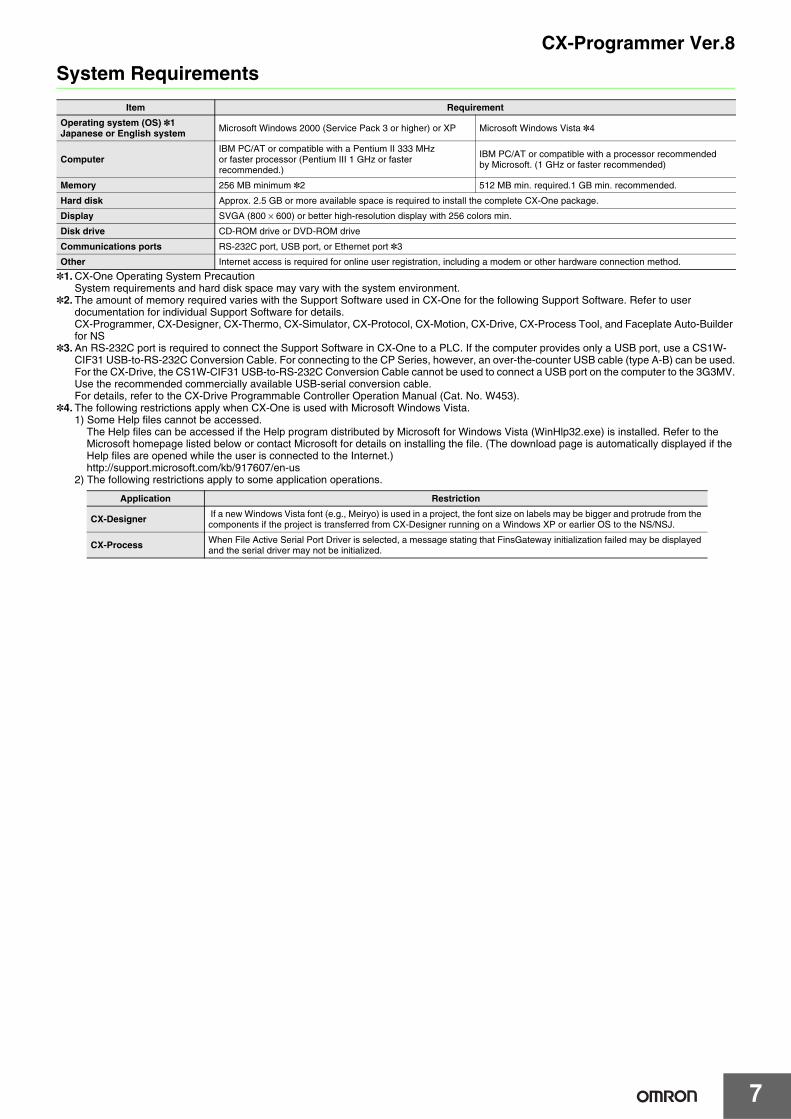
System Requirements
*1. CX-One Operating System PrecautionSystem requirements and hard disk space may vary with the system environment.
*2. The amount of memory required varies with the Support Software used in CX-One for the following Support Software. Refer to user documentation for individual Support Software for details.CX-Programmer, CX-Designer, CX-Thermo, CX-Simulator, CX-Protocol, CX-Motion, CX-Drive, CX-Process Tool, and Faceplate Auto-Builder for NS
*3. An RS-232C port is required to connect the Support Software in CX-One to a PLC. If the computer provides only a USB port, use a CS1W-CIF31 USB-to-RS-232C Conversion Cable. For connecting to the CP Series, however, an over-the-counter USB cable (type A-B) can be used.For the CX-Drive, the CS1W-CIF31 USB-to-RS-232C Conversion Cable cannot be used to connect a USB port on the computer to the 3G3MV.Use the recommended commercially available USB-serial conversion cable.For details, refer to the CX-Drive Programmable Controller Operation Manual (Cat. No. W453).
*4. The following restrictions apply when CX-One is used with Microsoft Windows Vista.1) Some Help files cannot be accessed.
The Help files can be accessed if the Help program distributed by Microsoft for Windows Vista (WinHlp32.exe) is installed. Refer to the Microsoft homepage listed below or contact Microsoft for details on installing the file. (The download page is automatically displayed if the Help files are opened while the user is connected to the Internet.)http://support.microsoft.com/kb/917607/en-us
2) The following restrictions apply to some application operations.
Item Requirement
Operating system (OS) *1Japanese or English system Microsoft Windows 2000 (Service Pack 3 or higher) or XP Microsoft Windows Vista *4
ComputerIBM PC/AT or compatible with a Pentium II 333 MHz or faster processor (Pentium III 1 GHz or faster recommended.)
IBM PC/AT or compatible with a processor recommendedby Microsoft. (1 GHz or faster recommended)
Memory 256 MB minimum *2 512 MB min. required.1 GB min. recommended.
Hard disk Approx. 2.5 GB or more available space is required to install the complete CX-One package.
Display SVGA (800 × 600) or better high-resolution display with 256 colors min.
Disk drive CD-ROM drive or DVD-ROM drive
Communications ports RS-232C port, USB port, or Ethernet port *3
Other Internet access is required for online user registration, including a modem or other hardware connection method.
Application Restriction
CX-Designer If a new Windows Vista font (e.g., Meiryo) is used in a project, the font size on labels may be bigger and protrude from the components if the project is transferred from CX-Designer running on a Windows XP or earlier OS to the NS/NSJ.
CX-Process When File Active Serial Port Driver is selected, a message stating that FinsGateway initialization failed may be displayed and the serial driver may not be initialized.
CX-Programmer Ver.8
8
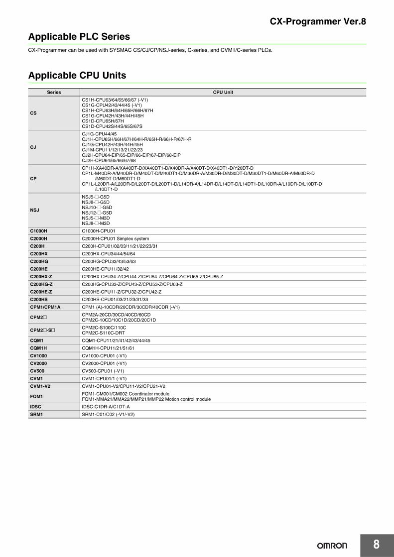
Applicable PLC SeriesCX-Programmer can be used with SYSMAC CS/CJ/CP/NSJ-series, C-series, and CVM1/C-series PLCs.
Applicable CPU Units
Series CPU Unit
CS
CS1H-CPU63/64/65/66/67 (-V1)CS1G-CPU42/43/44/45 (-V1)CS1H-CPU63H/64H/65H/66H/67HCS1G-CPU42H/43H/44H/45HCS1D-CPU65H/67HCS1D-CPU42S/44S/65S/67S
CJ
CJ1G-CPU44/45CJ1H-CPU65H/66H/67H/64H-R/65H-R/66H-R/67H-RCJ1G-CPU42H/43H/44H/45HCJ1M-CPU11/12/13/21/22/23CJ2H-CPU64-EIP/65-EIP/66-EIP/67-EIP/68-EIPCJ2H-CPU64/65/66/67/68
CP
CP1H-XA40DR-A/XA40DT-D/XA40DT1-D/X40DR-A/X40DT-D/X40DT1-D/Y20DT-DCP1L-M40DR-A/M40DR-D/M40DT-D/M40DT1-D/M30DR-A/M30DR-D/M30DT-D/M30DT1-D/M60DR-A/M60DR-D
/M60DT-D/M60DT1-DCP1L-L20DR-A/L20DR-D/L20DT-D/L20DT1-D/L14DR-A/L14DR-D/L14DT-D/L14DT1-D/L10DR-A/L10DR-D/L10DT-D
/L10DT1-D
NSJ
NSJ5-@-G5DNSJ8-@-G5DNSJ10-@-G5DNSJ12-@-G5DNSJ5-@-M3DNSJ8-@-M3D
C1000H C1000H-CPU01
C2000H C2000H-CPU01 Simplex system
C200H C200H-CPU01/02/03/11/21/22/23/31
C200HX C200HX-CPU34/44/54/64
C200HG C200HG-CPU33/43/53/63
C200HE C200HE-CPU11/32/42
C200HX-Z C200HX-CPU34-Z/CPU44-Z/CPU54-Z/CPU64-Z/CPU65-Z/CPU85-Z
C200HG-Z C200HG-CPU33-Z/CPU43-Z/CPU53-Z/CPU63-Z
C200HE-Z C200HE-CPU11-Z/CPU32-Z/CPU42-Z
C200HS C200HS-CPU01/03/21/23/31/33
CPM1/CPM1A CPM1 (A)-10CDR/20CDR/30CDR/40CDR (-V1)
CPM2@ CPM2A-20CD/30CD/40CD/60CDCPM2C-10CD/10C1D/20CD/20C1D
CPM2@-S@ CPM2C-S100C/110CCPM2C-S110C-DRT
CQM1 CQM1-CPU11/21/41/42/43/44/45
CQM1H CQM1H-CPU11/21/51/61
CV1000 CV1000-CPU01 (-V1)
CV2000 CV2000-CPU01 (-V1)
CV500 CV500-CPU01 (-V1)
CVM1 CVM1-CPU01/1 (-V1)
CVM1-V2 CVM1-CPU01-V2/CPU11-V2/CPU21-V2
FQM1 FQM1-CM001/CM002 Coordinator moduleFQM1-MMA21/MMA22/MMP21/MMP22 Motion control module
IDSC IDSC-C1DR-A/C1DT-A
SRM1 SRM1-C01/C02 (-V1/-V2)
9
CX-Programmer Ver.8
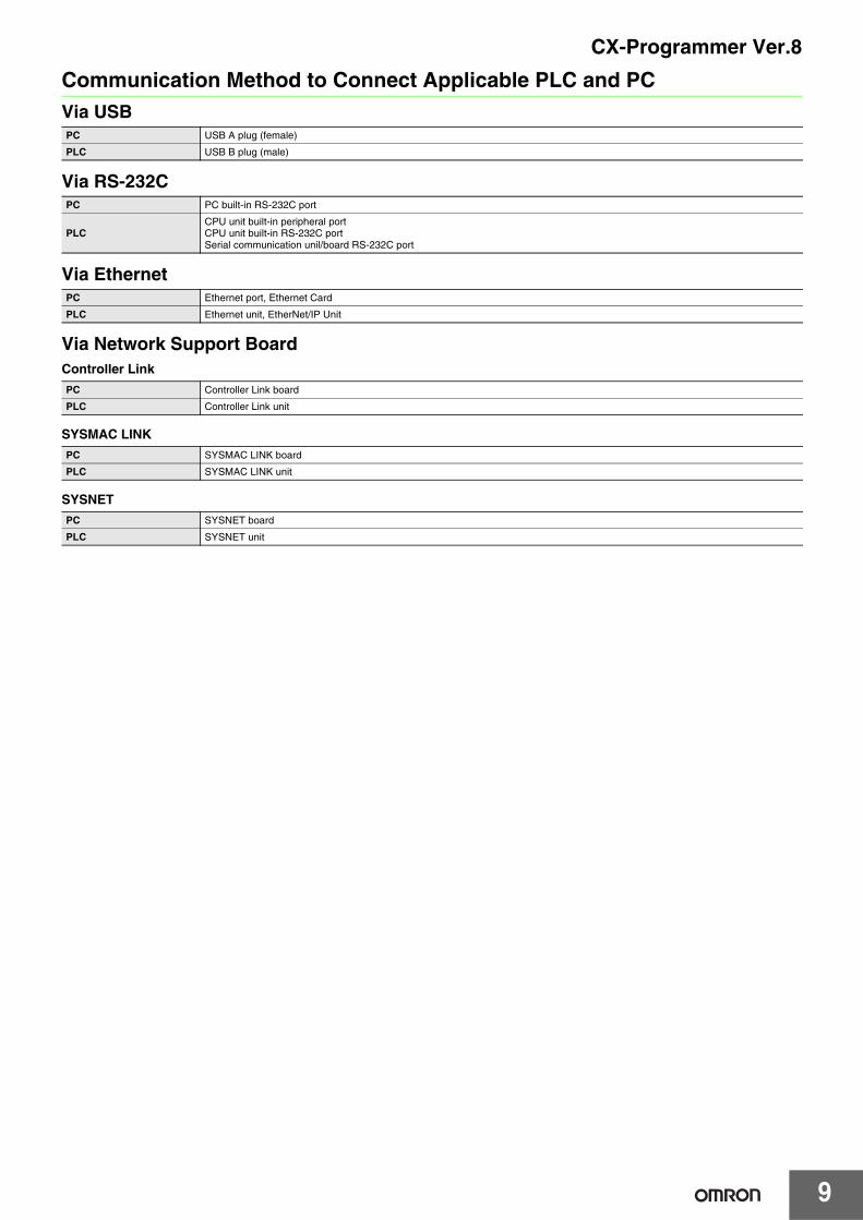
Communication Method to Connect Applicable PLC and PCVia USB
Via RS-232C
Via Ethernet
Via Network Support BoardController Link
SYSMAC LINK
SYSNET
PC USB A plug (female)
PLC USB B plug (male)
PC PC built-in RS-232C port
PLCCPU unit built-in peripheral port CPU unit built-in RS-232C portSerial communication unil/board RS-232C port
PC Ethernet port, Ethernet Card
PLC Ethernet unit, EtherNet/IP Unit
PC Controller Link board
PLC Controller Link unit
PC SYSMAC LINK board
PLC SYSMAC LINK unit
PC SYSNET board
PLC SYSNET unit
CX-Programmer Ver.8
10
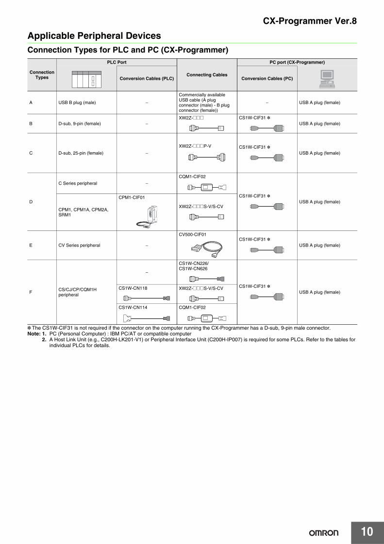
Applicable Peripheral DevicesConnection Types for PLC and PC (CX-Programmer)
* The CS1W-CIF31 is not required if the connector on the computer running the CX-Programmer has a D-sub, 9-pin male connector.Note: 1. PC (Personal Computer) : IBM PC/AT or compatible computer
2. A Host Link Unit (e.g., C200H-LK201-V1) or Peripheral Interface Unit (C200H-IP007) is required for some PLCs. Refer to the tables for individual PLCs for details.
ConnectionTypes
PLC Port
Connecting Cables
PC port (CX-Programmer)
Conversion Cables (PLC) Conversion Cables (PC)
A USB B plug (male) −
Commercially available USB cable (A plug connector (male) - B plug connector (female))
− USB A plug (female)
B D-sub, 9-pin (female) −XW2Z-@@@ CS1W-CIF31 *
USB A plug (female)
C D-sub, 25-pin (female) −XW2Z-@@@P-V CS1W-CIF31 *
USB A plug (female)
D
C Series peripheral −CQM1-CIF02
CS1W-CIF31 *USB A plug (female)
CPM1, CPM1A, CPM2A, SRM1
CPM1-CIF01
XW2Z-@@@S-V/S-CV
E CV Series peripheral −
CV500-CIF01CS1W-CIF31 *
USB A plug (female)
F CS/CJ/CP/CQM1Hperipheral
−
CS1W-CN226/CS1W-CN626
CS1W-CIF31 *USB A plug (female)
CS1W-CN118 XW2Z-@@@S-V/S-CV
CS1W-CN114 CQM1-CIF02
CX-Programmer Ver.8
11
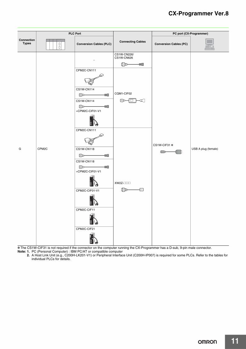
* The CS1W-CIF31 is not required if the connector on the computer running the CX-Programmer has a D-sub, 9-pin male connector.Note: 1. PC (Personal Computer) : IBM PC/AT or compatible computer
2. A Host Link Unit (e.g., C200H-LK201-V1) or Peripheral Interface Unit (C200H-IP007) is required for some PLCs. Refer to the tables for individual PLCs for details.
ConnectionTypes
PLC Port
Connecting Cables
PC port (CX-Programmer)
Conversion Cables (PLC) Conversion Cables (PC)
G CPM2C
−
CS1W-CN226/CS1W-CN626
CS1W-CIF31 *USB A plug (female)
CPM2C-CN111
CQM1-CIF02
CS1W-CN114
CS1W-CN114
+CPM2C-CIF01-V1
CPM2C-CN111
XW2Z-@@@
CS1W-CN118
CS1W-CN118
+CPM2C-CIF01-V1
CPM2C-CIF01-V1
CPM2C-CIF11
CPM2C-CIF21
CX-Programmer Ver.8
12
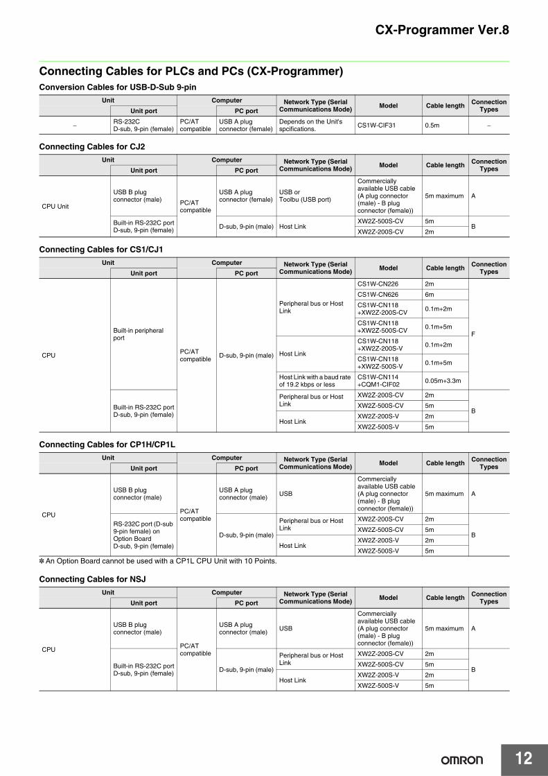
Connecting Cables for PLCs and PCs (CX-Programmer)Conversion Cables for USB-D-Sub 9-pin
Connecting Cables for CJ2
Connecting Cables for CS1/CJ1
Connecting Cables for CP1H/CP1L
* An Option Board cannot be used with a CP1L CPU Unit with 10 Points.
Connecting Cables for NSJ
Unit Computer Network Type (Serial Communications Mode) Model Cable length Connection
TypesUnit port PC port
− RS-232CD-sub, 9-pin (female)
PC/ATcompatible
USB A plug connector (female)
Depends on the Unit's spcifications. CS1W-CIF31 0.5m −
Unit Computer Network Type (Serial Communications Mode) Model Cable length Connection
TypesUnit port PC port
CPU Unit
USB B plug connector (male) PC/AT
compatible
USB A plug connector (female)
USB orToolbu (USB port)
Commercially available USB cable (A plug connector (male) - B plug connector (female))
5m maximum A
Built-in RS-232C portD-sub, 9-pin (female) D-sub, 9-pin (male) Host Link
XW2Z-500S-CV 5mB
XW2Z-200S-CV 2m
Unit Computer Network Type (Serial Communications Mode) Model Cable length Connection
TypesUnit port PC port
CPU
Built-in peripheral port
PC/ATcompatible D-sub, 9-pin (male)
Peripheral bus or Host Link
CS1W-CN226 2m
F
CS1W-CN626 6m
CS1W-CN118+XW2Z-200S-CV 0.1m+2m
CS1W-CN118+XW2Z-500S-CV 0.1m+5m
Host Link
CS1W-CN118+XW2Z-200S-V 0.1m+2m
CS1W-CN118+XW2Z-500S-V 0.1m+5m
Host Link with a baud rate of 19.2 kbps or less
CS1W-CN114+CQM1-CIF02 0.05m+3.3m
Built-in RS-232C portD-sub, 9-pin (female)
Peripheral bus or Host Link
XW2Z-200S-CV 2m
BXW2Z-500S-CV 5m
Host LinkXW2Z-200S-V 2m
XW2Z-500S-V 5m
Unit Computer Network Type (Serial Communications Mode) Model Cable length Connection
TypesUnit port PC port
CPU
USB B plug connector (male)
PC/ATcompatible
USB A plug connector (male) USB
Commercially available USB cable (A plug connector (male) - B plug connector (female))
5m maximum A
RS-232C port (D-sub 9-pin female) on Option BoardD-sub, 9-pin (female)
D-sub, 9-pin (male)
Peripheral bus or Host Link
XW2Z-200S-CV 2m
BXW2Z-500S-CV 5m
Host LinkXW2Z-200S-V 2m
XW2Z-500S-V 5m
Unit Computer Network Type (Serial Communications Mode) Model Cable length Connection
TypesUnit port PC port
CPU
USB B plug connector (male)
PC/ATcompatible
USB A plug connector (male) USB
Commercially available USB cable (A plug connector (male) - B plug connector (female))
5m maximum A
Built-in RS-232C portD-sub, 9-pin (female) D-sub, 9-pin (male)
Peripheral bus or Host Link
XW2Z-200S-CV 2m
BXW2Z-500S-CV 5m
Host LinkXW2Z-200S-V 2m
XW2Z-500S-V 5m
13
CX-Programmer Ver.8
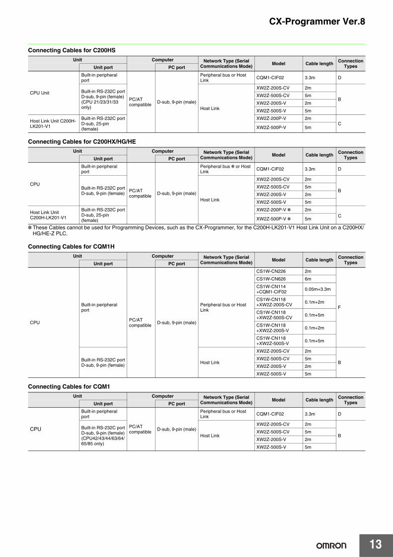
Connecting Cables for C200HS
Connecting Cables for C200HX/HG/HE
* These Cables cannot be used for Programming Devices, such as the CX-Programmer, for the C200H-LK201-V1 Host Link Unit on a C200HX/HG/HE-Z PLC.
Connecting Cables for CQM1H
Connecting Cables for CQM1
Unit Computer Network Type (Serial Communications Mode) Model Cable length Connection
TypesUnit port PC port
CPU Unit
Built-in peripheral port
PC/ATcompatible D-sub, 9-pin (male)
Peripheral bus or Host Link CQM1-CIF02 3.3m D
Built-in RS-232C portD-sub, 9-pin (female) (CPU 21/23/31/33 only) Host Link
XW2Z-200S-CV 2m
BXW2Z-500S-CV 5m
XW2Z-200S-V 2m
XW2Z-500S-V 5m
Host Link Unit C200H-LK201-V1
Built-in RS-232C portD-sub, 25-pin (female)
XW2Z-200P-V 2mC
XW2Z-500P-V 5m
Unit Computer Network Type (Serial Communications Mode) Model Cable length Connection
TypesUnit port PC port
CPU
Built-in peripheral port
PC/ATcompatible D-sub, 9-pin (male)
Peripheral bus * or Host Link CQM1-CIF02 3.3m D
Built-in RS-232C portD-sub, 9-pin (female)
Host Link
XW2Z-200S-CV 2m
BXW2Z-500S-CV 5m
XW2Z-200S-V 2m
XW2Z-500S-V 5m
Host Link UnitC200H-LK201-V1
Built-in RS-232C portD-sub, 25-pin (female)
XW2Z-200P-V * 2mC
XW2Z-500P-V * 5m
Unit Computer Network Type (Serial Communications Mode) Model Cable length Connection
TypesUnit port PC port
CPU
Built-in peripheral port
PC/ATcompatible D-sub, 9-pin (male)
Peripheral bus or Host Link
CS1W-CN226 2m
F
CS1W-CN626 6m
CS1W-CN114+CQM1-CIF02 0.05m+3.3m
CS1W-CN118+XW2Z-200S-CV 0.1m+2m
CS1W-CN118+XW2Z-500S-CV 0.1m+5m
CS1W-CN118+XW2Z-200S-V 0.1m+2m
CS1W-CN118+XW2Z-500S-V 0.1m+5m
Built-in RS-232C portD-sub, 9-pin (female) Host Link
XW2Z-200S-CV 2m
BXW2Z-500S-CV 5m
XW2Z-200S-V 2m
XW2Z-500S-V 5m
Unit Computer Network Type (Serial Communications Mode) Model Cable length Connection
TypesUnit port PC port
CPU
Built-in peripheral port
PC/ATcompatible D-sub, 9-pin (male)
Peripheral bus or Host Link CQM1-CIF02 3.3m D
Built-in RS-232C portD-sub, 9-pin (female)(CPU42/43/44/63/64/65/85 only)
Host Link
XW2Z-200S-CV 2m
BXW2Z-500S-CV 5m
XW2Z-200S-V 2m
XW2Z-500S-V 5m
CX-Programmer Ver.8
14
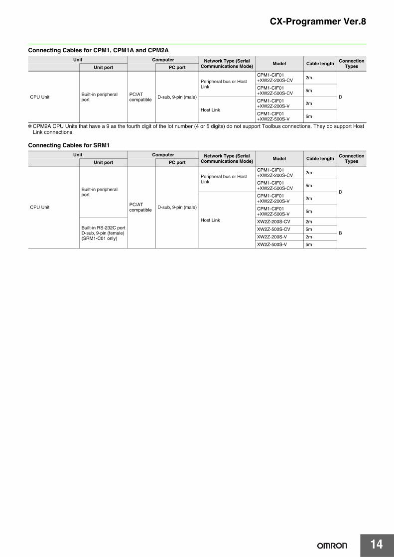
Connecting Cables for CPM1, CPM1A and CPM2A
* CPM2A CPU Units that have a 9 as the fourth digit of the lot number (4 or 5 digits) do not support Toolbus connections. They do support Host Link connections.
Connecting Cables for SRM1
Unit Computer Network Type (Serial Communications Mode) Model Cable length Connection
TypesUnit port PC port
CPU Unit Built-in peripheral port
PC/ATcompatible D-sub, 9-pin (male)
Peripheral bus or Host Link
CPM1-CIF01+XW2Z-200S-CV 2m
D
CPM1-CIF01+XW2Z-500S-CV 5m
Host Link
CPM1-CIF01+XW2Z-200S-V 2m
CPM1-CIF01+XW2Z-500S-V 5m
Unit Computer Network Type (Serial Communications Mode) Model Cable length Connection
TypesUnit port PC port
CPU Unit
Built-in peripheral port
PC/ATcompatible D-sub, 9-pin (male)
Peripheral bus or Host Link
CPM1-CIF01+XW2Z-200S-CV 2m
D
CPM1-CIF01+XW2Z-500S-CV 5m
Host Link
CPM1-CIF01+XW2Z-200S-V 2m
CPM1-CIF01+XW2Z-500S-V 5m
Built-in RS-232C portD-sub, 9-pin (female) (SRM1-C01 only)
XW2Z-200S-CV 2m
BXW2Z-500S-CV 5m
XW2Z-200S-V 2m
XW2Z-500S-V 5m
15
CX-Programmer Ver.8
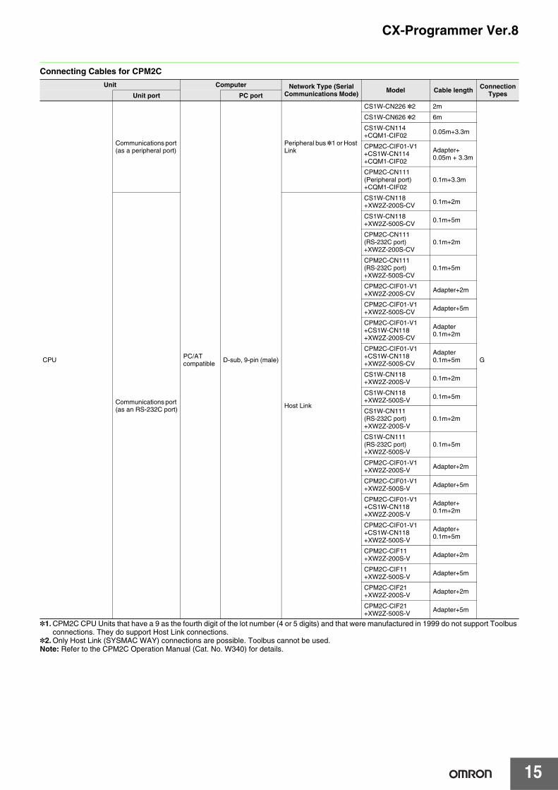
Connecting Cables for CPM2C
*1. CPM2C CPU Units that have a 9 as the fourth digit of the lot number (4 or 5 digits) and that were manufactured in 1999 do not support Toolbus connections. They do support Host Link connections.
*2. Only Host Link (SYSMAC WAY) connections are possible. Toolbus cannot be used.Note: Refer to the CPM2C Operation Manual (Cat. No. W340) for details.
Unit Computer Network Type (Serial Communications Mode) Model Cable length Connection
TypesUnit port PC port
CPU
Communications port (as a peripheral port)
PC/ATcompatible D-sub, 9-pin (male)
Peripheral bus *1 or Host Link
CS1W-CN226 *2 2m
G
CS1W-CN626 *2 6m
CS1W-CN114+CQM1-CIF02 0.05m+3.3m
CPM2C-CIF01-V1+CS1W-CN114+CQM1-CIF02
Adapter+ 0.05m + 3.3m
CPM2C-CN111(Peripheral port)+CQM1-CIF02
0.1m+3.3m
Communications port (as an RS-232C port) Host Link
CS1W-CN118+XW2Z-200S-CV 0.1m+2m
CS1W-CN118+XW2Z-500S-CV 0.1m+5m
CPM2C-CN111 (RS-232C port)+XW2Z-200S-CV
0.1m+2m
CPM2C-CN111 (RS-232C port)+XW2Z-500S-CV
0.1m+5m
CPM2C-CIF01-V1+XW2Z-200S-CV Adapter+2m
CPM2C-CIF01-V1+XW2Z-500S-CV Adapter+5m
CPM2C-CIF01-V1+CS1W-CN118+XW2Z-200S-CV
Adapter 0.1m+2m
CPM2C-CIF01-V1+CS1W-CN118+XW2Z-500S-CV
Adapter 0.1m+5m
CS1W-CN118+XW2Z-200S-V 0.1m+2m
CS1W-CN118+XW2Z-500S-V 0.1m+5m
CS1W-CN111(RS-232C port)+XW2Z-200S-V
0.1m+2m
CS1W-CN111(RS-232C port)+XW2Z-500S-V
0.1m+5m
CPM2C-CIF01-V1+XW2Z-200S-V Adapter+2m
CPM2C-CIF01-V1+XW2Z-500S-V Adapter+5m
CPM2C-CIF01-V1+CS1W-CN118+XW2Z-200S-V
Adapter+0.1m+2m
CPM2C-CIF01-V1+CS1W-CN118+XW2Z-500S-V
Adapter+0.1m+5m
CPM2C-CIF11+XW2Z-200S-V Adapter+2m
CPM2C-CIF11+XW2Z-500S-V Adapter+5m
CPM2C-CIF21+XW2Z-200S-V Adapter+2m
CPM2C-CIF21+XW2Z-500S-V Adapter+5m
CX-Programmer Ver.8
16
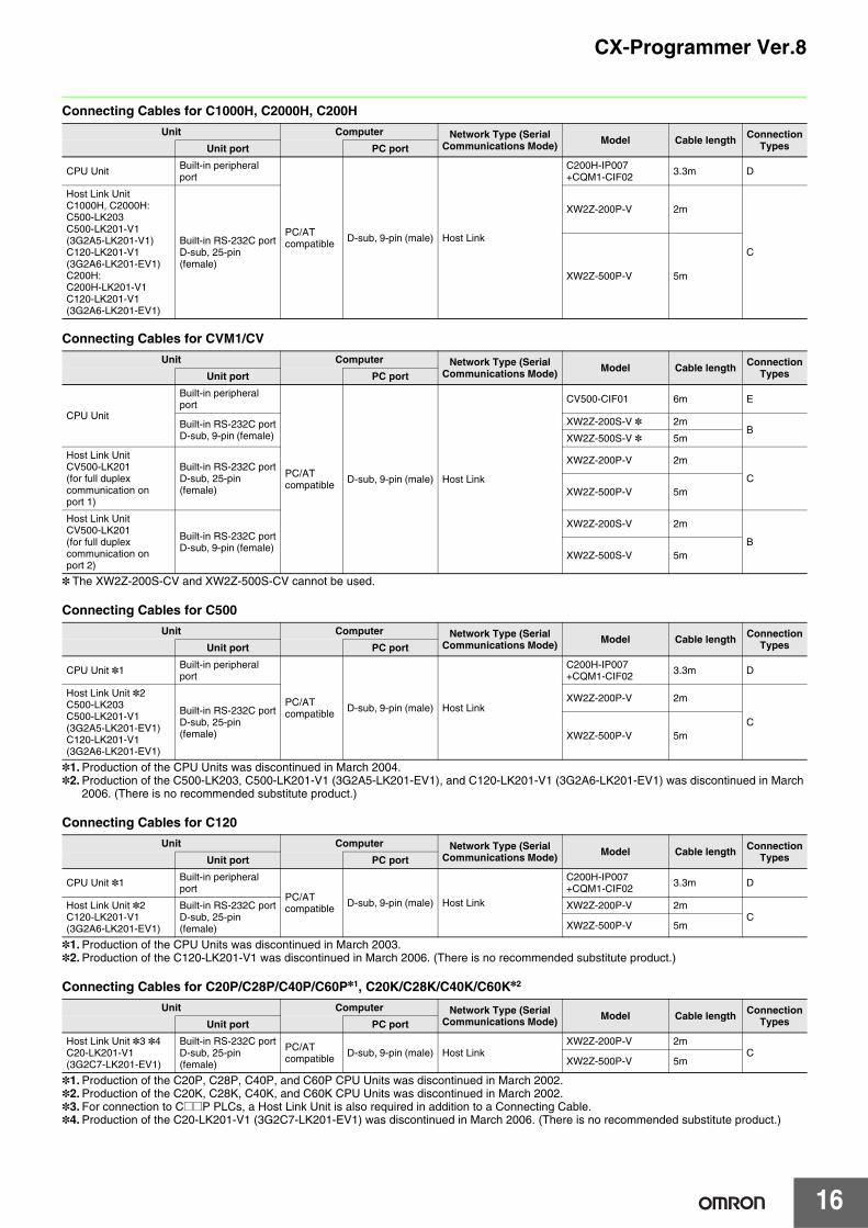
Connecting Cables for C1000H, C2000H, C200H
Connecting Cables for CVM1/CV
* The XW2Z-200S-CV and XW2Z-500S-CV cannot be used.
Connecting Cables for C500
*1. Production of the CPU Units was discontinued in March 2004.*2. Production of the C500-LK203, C500-LK201-V1 (3G2A5-LK201-EV1), and C120-LK201-V1 (3G2A6-LK201-EV1) was discontinued in March
2006. (There is no recommended substitute product.)
Connecting Cables for C120
*1. Production of the CPU Units was discontinued in March 2003.*2. Production of the C120-LK201-V1 was discontinued in March 2006. (There is no recommended substitute product.)
Connecting Cables for C20P/C28P/C40P/C60P*1, C20K/C28K/C40K/C60K*2
*1. Production of the C20P, C28P, C40P, and C60P CPU Units was discontinued in March 2002.*2. Production of the C20K, C28K, C40K, and C60K CPU Units was discontinued in March 2002.*3. For connection to C@@P PLCs, a Host Link Unit is also required in addition to a Connecting Cable.*4. Production of the C20-LK201-V1 (3G2C7-LK201-EV1) was discontinued in March 2006. (There is no recommended substitute product.)
Unit Computer Network Type (Serial Communications Mode) Model Cable length Connection
TypesUnit port PC port
CPU Unit Built-in peripheral port
PC/ATcompatible D-sub, 9-pin (male) Host Link
C200H-IP007+CQM1-CIF02 3.3m D
Host Link UnitC1000H, C2000H:C500-LK203C500-LK201-V1(3G2A5-LK201-V1)C120-LK201-V1(3G2A6-LK201-EV1)C200H:C200H-LK201-V1C120-LK201-V1(3G2A6-LK201-EV1)
Built-in RS-232C portD-sub, 25-pin (female)
XW2Z-200P-V 2m
C
XW2Z-500P-V 5m
Unit Computer Network Type (Serial Communications Mode) Model Cable length Connection
TypesUnit port PC port
CPU Unit
Built-in peripheral port
PC/ATcompatible D-sub, 9-pin (male) Host Link
CV500-CIF01 6m E
Built-in RS-232C portD-sub, 9-pin (female)
XW2Z-200S-V * 2mB
XW2Z-500S-V * 5m
Host Link UnitCV500-LK201(for full duplex communication on port 1)
Built-in RS-232C portD-sub, 25-pin (female)
XW2Z-200P-V 2m
CXW2Z-500P-V 5m
Host Link UnitCV500-LK201(for full duplex communication on port 2)
Built-in RS-232C portD-sub, 9-pin (female)
XW2Z-200S-V 2m
BXW2Z-500S-V 5m
Unit Computer Network Type (Serial Communications Mode) Model Cable length Connection
TypesUnit port PC port
CPU Unit *1 Built-in peripheral port
PC/ATcompatible D-sub, 9-pin (male) Host Link
C200H-IP007+CQM1-CIF02 3.3m D
Host Link Unit *2C500-LK203C500-LK201-V1(3G2A5-LK201-EV1)C120-LK201-V1(3G2A6-LK201-EV1)
Built-in RS-232C portD-sub, 25-pin (female)
XW2Z-200P-V 2m
CXW2Z-500P-V 5m
Unit Computer Network Type (Serial Communications Mode) Model Cable length Connection
TypesUnit port PC port
CPU Unit *1 Built-in peripheral port
PC/ATcompatible D-sub, 9-pin (male) Host Link
C200H-IP007+CQM1-CIF02 3.3m D
Host Link Unit *2C120-LK201-V1(3G2A6-LK201-EV1)
Built-in RS-232C portD-sub, 25-pin (female)
XW2Z-200P-V 2mC
XW2Z-500P-V 5m
Unit Computer Network Type (Serial Communications Mode) Model Cable length Connection
TypesUnit port PC port
Host Link Unit *3 *4C20-LK201-V1(3G2C7-LK201-EV1)
Built-in RS-232C portD-sub, 25-pin (female)
PC/ATcompatible D-sub, 9-pin (male) Host Link
XW2Z-200P-V 2mC
XW2Z-500P-V 5m
17
CX-Programmer Ver.8
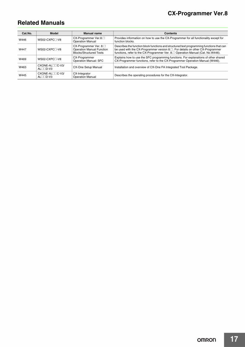
Related Manuals
Cat.No. Model Manual name Contents
W446 WS02-CXPC@-V8 CX-Programmer Ver.8.@ Operation Manual
Provides information on how to use the CX-Programmer for all functionality except for function blocks.
W447 WS02-CXPC@-V8CX-Programmer Ver. 8.@ Operation Manual Function Blocks/Structured Texts
Describes the function block functions and structured text programming functions that can be used with the CX-Programmer version 8.@. For details on other CX-Programmer functions, refer to the CX-Programmer Ver. 8.@ Operation Manual (Cat. No.W446).
W469 WS02-CXPC@-V8 CX-Programmer Operation Manual: SFC
Explains how to use the SFC programming functions. For explanations of other shared CX-Programmer functions, refer to the CX-Programmer Operation Manual (W446).
W463 CXONE-AL@@C-V3/AL@@D-V3 CX-One Setup Manual Installation and overview of CX-One FA Integrated Tool Package.
W445 CXONE-AL@@C-V3/AL@@D-V3
CX-Integrator Operation Manual Describes the operating procedures for the CX-Integrator.
Read and Understand This Catalog Please read and understand this catalog before purchasing the products. Please consult your OMRON representative if you have any questions or comments.
Warranty and Limitations of Liability WARRANTY OMRON's exclusive warranty is that the products are free from defects in materials and workmanship for a period of one year (or other period if specified) from date of sale by OMRON. OMRON MAKES NO WARRANTY OR REPRESENTATION, EXPRESS OR IMPLIED, REGARDING NON-INFRINGEMENT, MERCHANTABILITY, OR FITNESS FOR PARTICULAR PURPOSE OF THE PRODUCTS. ANY BUYER OR USER ACKNOWLEDGES THAT THE BUYER OR USER ALONE HAS DETERMINED THAT THE PRODUCTS WILL SUITABLY MEET THE REQUIREMENTS OF THEIR INTENDED USE. OMRON DISCLAIMS ALL OTHER WARRANTIES, EXPRESS OR IMPLIED. LIMITATIONS OF LIABILITY OMRON SHALL NOT BE RESPONSIBLE FOR SPECIAL, INDIRECT, OR CONSEQUENTIAL DAMAGES, LOSS OF PROFITS OR COMMERCIAL LOSS IN ANY WAY CONNECTED WITH THE PRODUCTS, WHETHER SUCH CLAIM IS BASED ON CONTRACT, WARRANTY, NEGLIGENCE, OR STRICT LIABILITY. In no event shall the responsibility of OMRON for any act exceed the individual price of the product on which liability is asserted. IN NO EVENT SHALL OMRON BE RESPONSIBLE FOR WARRANTY, REPAIR, OR OTHER CLAIMS REGARDING THE PRODUCTS UNLESS OMRON'S ANALYSIS CONFIRMS THAT THE PRODUCTS WERE PROPERLY HANDLED, STORED, INSTALLED, AND MAINTAINED AND NOT SUBJECT TO CONTAMINATION, ABUSE, MISUSE, OR INAPPROPRIATE MODIFICATION OR REPAIR.
Application Considerations SUITABILITY FOR USE OMRON shall not be responsible for conformity with any standards, codes, or regulations that apply to the combination of products in the customer's application or use of the products. At the customer's request, OMRON will provide applicable third party certification documents identifying ratings and limitations of use that apply to the products. This information by itself is not sufficient for a complete determination of the suitability of the products in combination with the end product, machine, system, or other application or use. The following are some examples of applications for which particular attention must be given. This is not intended to be an exhaustive list of all possible uses of the products, nor is it intended to imply that the uses listed may be suitable for the products:
• Outdoor use, uses involving potential chemical contamination or electrical interference, or conditions or uses not described in this catalog. • Nuclear energy control systems, combustion systems, railroad systems, aviation systems, medical equipment, amusement machines, vehicles,
safety equipment, and installations subject to separate industry or government regulations. • Systems, machines, and equipment that could present a risk to life or property.
Please know and observe all prohibitions of use applicable to the products. NEVER USE THE PRODUCTS FOR AN APPLICATION INVOLVING SERIOUS RISK TO LIFE OR PROPERTY WITHOUT ENSURING THAT THE SYSTEM AS A WHOLE HAS BEEN DESIGNED TO ADDRESS THE RISKS, AND THAT THE OMRON PRODUCTS ARE PROPERLY RATED AND INSTALLED FOR THE INTENDED USE WITHIN THE OVERALL EQUIPMENT OR SYSTEM. PROGRAMMABLE PRODUCTS OMRON shall not be responsible for the user's programming of a programmable product, or any consequence thereof.
Disclaimers CHANGE IN SPECIFICATIONS Product specifications and accessories may be changed at any time based on improvements and other reasons. It is our practice to change model numbers when published ratings or features are changed, or when significant construction changes are made. However, some specifications of the products may be changed without any notice. When in doubt, special model numbers may be assigned to fix or establish key specifications for your application on your request. Please consult with your OMRON representative at any time to confirm actual specifications of purchased products. DIMENSIONS AND WEIGHTS Dimensions and weights are nominal and are not to be used for manufacturing purposes, even when tolerances are shown. PERFORMANCE DATA Performance data given in this catalog is provided as a guide for the user in determining suitability and does not constitute a warranty. It may represent the result of OMRON’s test conditions, and the users must correlate it to actual application requirements. Actual performance is subject to the OMRON Warranty and Limitations of Liability. ERRORS AND OMISSIONS The information in this document has been carefully checked and is believed to be accurate; however, no responsibility is assumed for clerical, typographical, or proofreading errors, or omissions.
2009.5
In the interest of product improvement, specifications are subject to change without notice.
OMRON Corporation Industrial Automation Company http://www.ia.omron.com/
(c)Copyright OMRON Corporation 2009 All Right Reserved.