faa related for · lucas aerospace limited normalair-garrett limited penny and giles avionic...
TRANSCRIPT

'
COPT J
DOT/FAA/CT-92/27
FAA Technical Center Atlantic City International Airport N.J. 08405
Aircraft Ice Detectors and Related J~chnologies for
·····-· .. ::::-·:::··.-:-·-:;-·: ...... .
April 1993
Final Report
0 U.S. Department of Transportation Federal Aviation Administration

of of
DOT/FAA /CT-92/ 27 c.l
This the U. inform,
assumes n•
The or manu fa, herein so: objective
Hoover, George A. Aircraft ice detectors and related technologies for
sorship interest 1.ment !Of.
products ppear 1 to the

1. Report No. 2. Government Accession No.
DOT/FAA/CT-92/27
4. Title and Subtitle
AIRCRAFT ICE DETECTORS AND RELATED TECHNOLOGIES FOR ONGROUND AND INFLIGHT APPLICATIONS
Technical keport Documentation Page
3. Recipient's Catalog No.
5. Report Dote
April 1993 6. Performing Orgoni zotion Code
1------------------------------------1 B. Performing Organo zotion Report No. 7. Author/ s)
Gregory A. Hoover
9. Performing Organization Nome and Address
Galaxy Scientific Corporation 2500 English Creek Avenue, Building 11 Pleasantville, NJ 08232
10. Work Unit No. (TRAIS)
11. Contract or Grant No.
DTFA03-89-C-00043
13. Type of Report and Period Covered ~--------------~~----------------------~ 12. Sponsoring Agency Nome and Address
U.S. Department of Transportation Federal Aviation Administration Technical Center
Final Report
14. Sponsoring Agency Code
Atlantic City International Airport, NJ 08405 ACD-230 -----------~
15. Supplementary Notes
FAA Program Manager: Charles Masters
16. Abstract
This report describes a number of ice detection systems and identifies companies which produce ice detection systems. Twenty-two companies were contacted for this report. Of these companies, 16 satisfied the criteria for inclusion in the report. Systems described in this report include inflight, onground, combined inflight and onground, and related technologies. Each technology category features a "Promising Technologies" section. In these sections, future ice detections systems are discussed.
17. Key Wards
Aircraft Ice Detection Aircraft Icing Ice Detection Technology
19. Security Classil. (of this report)
Unclassified
Form DOT F 1700.7 <B-72l
18. Distribution Statement
Document is available to the public through the National Technical Information Service, Springfield, Virginia 22161
20. Security Classif. (of this page) 21. No. of Pages 22. Price
Unclassified 52
Reproduction of completed page outhori zed

PREFACE
Appreciation is expressed to the FAA Technical Center Library and the companies and manufacturers listed in this report for providing valuable information and support.
iii

TABLE OF CONTENTS
EXECUTIVE SUMMARY
INTRODUCTION
Background Scope
INFLIGHT ICE DETECTION SYSTEMS
Lucas Aerospace Limited Normalair-Garrett Limited Penny and Giles Avionic Systems Limited Rosemount Incorporated Sunstrand Corporation Vibro-Meter Corporation
PROMISING TECHNOLOGIES {lnflight)
Simmonds Precision
ONGROUND ICE DETECTION SYSTEMS
Finnair McDonnell Douglas Corporation O'Connor Ladder Company Incorporated Rosemount Incorporated Vitachrome Graphics Wahl Instruments Incorporated
PROMISING TECHNOLOGIES (Onground)
Airborne CCTV Bolvad Communications FMC Corporation lnstrumar Limited
iv
ix
1
1 2
3
3 5 6 8
11 13
15
15
18
18 19 20 22 24 25
28
28 29 30 31

COMBINED ONGROUND AND INFLIGHT ICE DETECTION SYSTEMS 33
Dataproducts New England Incorporated 33 Vibro-Meter Corporation 34
PROMISING TECHNOLOGIES (combined Onground and lnflight) 37
Ideal Research Incorporated 37
RELATED TECHNOLOGIES 39
Dataproducts New England Incorporated 39 lnstrumar Limited 40 Normalair-Garrett Limited 41 Rosemount Incorporated 42
v

LIST OF FIGURES
Figure Page
1 LUCAS (Mk3) 5
2 NORMALAIR-GARRETT (Hot Rod Ice Detector) 6
3 PENNY AND GILES ICE DETECTOR 8
4 ROSEMOUNT (Model 871 CV Magnetostrictive Ice Detector) 11
5 SUNSTRAND ICE DETECTOR 12
6 VIBRO-METER (Model EW134) 14
7 FINNAIR ICE DETECTOR 19
8 MCDONNELL DOUGLAS CLEAR ICE DETECTOR 20
9 O'CONNOR LADDER (Model 412-9-SP) 21
10 ROSEMOUNT (Surface Ice Detectors) 24
11 VITACHROME (Tuft and Decal) 25
12 WAHL (Heat Spy) 27
13 DATAPRODUCTS (Model 6316-9) 34
14 VIBRO-METER OVERWING ICE DETECTOR 36
vi

ac approx. BITE oc ceo CCTV ccu cps diam. ONE DOT OF FAA FAR FS ft ft•lb g h HOT Hz IDMS in IR kb kg kHz kn kPa lb LCD LRU LWC max MIAMI min mm ms MSO MTBF
LIST OF ABBREVIATIONS
Alternating Current Approximately Built in Test Equipment degrees Celsius Charge Coupled Device Closed Circuit Television Camera Control Unit Cycles per Second Diameter Dataproducts New England Department of Transportation degrees Fahrenheit Federal Aviation Administration Federal Aviation Regulation Full Scale Foot foot-pound Gram Hour Heat of Transformation Hertz Ice Detection and Measuring System Inch Infrared Kilobyte Kilogram Kilohertz Knot Kilo Pascals Pound Liquid Crystal Display Line Replaceable Unit Liquid Water Content Maximum Microwave Ice Accretion Measurement Instrument Minute Millimeter Millisecond Magnetostrictive Oscillator Mean Time Between Failure
vii

OAT PCC psi rh s Si SSSID TFPRT v Vac Vdc w
Outside Air Temperature Piezoelectric Ceramic Crystal Pounds per Square Inch Relative Humidity Second Silicon Surface Solid-State Ice Detector Thin Film Platinum Resistance Thermometer Volts Volts Alternating Current Volts Direct Current Watts
viii

EXECUTIVE SUMMARY
Throughout aviation history, icing conditions have caused a significant number of accidents. As technology has advanced, improved methods of ice detection have been developed. This report identifies ice detection companies and documents the systems they produce for the aviation industry. The goal of this report is to provide a current list of available ice detection systems. Ice detection systems that are in the development stages and not yet available are included in the Promising Technologies sections of this report. The main approach used in achieving this goal was to contact the ice detection companies and examine the data that they provided. The data were assessed on these criteria: the device was an ice detector or a related technology, or a system or technology currently in the development stage.
This survey/study was initiated and completed in 1993, therefore it is only representative of those technologies during this time frame. A follow-on survey/study is in progress, which will update the technologies and provide information on those recent research efforts by the Federal Aviation Administration (FAA), industry, and academia.
The main source of data for this report was ice detection companies. They provided data to make the contents of this report accurate and complete. Another source used to collect data for this report was a literature search conducted at the FAA Technical Center Library. A total of 22 companies provided information. Of those companies, 16 met the criteria necessary for inclusion in this report.
There are four technology categories in this report: onground ice detection systems, inflight ice detection systems, combined onground and inflight ice detection systems, and related technologies. Each of these will include a subsection entitled "Promising Technologies." Companies identified in this report are described as follows:
• Company name and theory of operation • System description • Technical specifications • Point of contact
It must be stated that no evaluation of the systems was performed and no comparison between systems was made.
ix

INTRODUCTION
Background
It is a vital part of flight safety to inform the flight crew of ice or icing conditions. The formation of ice can take place anywhere on an aircraft surface including engines and air induction systems. The formation of ice can occur in many ways and in many conditions. During flight, ice can accumulate when the aircraft flies through clouds containing supercooled water droplets. These clouds contain droplets of water which are suspended in a liquid state. Although water normally freezes at temperatures below 32 degrees Fahrenheit (°F), the water droplets in an icing cloud are suspended in a supercooled unstable state as long as nothing is present on which the first ice crystal can form. Disturbance of this state causes the droplets to freeze. Ice accumulation on inflight aircraft may include rime ice, glaze ice, runback ice, and mixed ice. Rime ice is a frosty ice formation occurring at very cold temperatures during which the freezing process is rapid. Glaze ice often occurs at temperatures near freezing. The resulting ice formation often is clear because the droplets run along the surface before they freeze. This eliminates most air pockets. Runback ice may occur when impinging droplets do not freeze instantly upon impact and the liquid water "runs back" and freezes beyond the leading edge of the wing. Mixed ice is a hybrid of glaze and rime ice and forms as a result of fluctuating temperatures.
Ice may build up on an aircraft during conditions of snow, freezing rain, hail, supercooled fog, or frost. Dry snow by itself is not critical to airframe icing but in combination with supercooled droplets (mixed conditions) or in temperatures only slightly below freezing (wet snow) can create conditions where ice accretion is extremely rapid. Freezing rain usually takes place when large supercooled droplets make contact with the ground or any exposed surface. Hail is small balls or chunks of ice or snow with diameters of 0.1 to 3 inches that are developed in cumulonimbus clouds. Supercooled fog represents a fog or low cloud composed of supercooled water droplets. Frost is a thin layer of crystalline ice that forms on exposed surfaces when the temperature of these surfaces drops below 32 °F even though the outside air temperature (OAT) may be above freezing.
Ice buildup on airframes causes many concerns. Ice accretion usually results in loss of performance and loss of operational safety. Ice buildup can cause decrease in lift and increase in weight, drag, and stalling speed. The overall effect on the aircraft is loss of aerodynamic efficiency, engine power, or control surface efficiency, and increase in fuel consumption. Another danger is engine ingestion of the shed ice and subsequent damage or engine failure.
There are three ways a flight crew can be warned of the onset of ice-all have application for both onground and inflight use. The most basic technique is "meteorological prediction." The pilot needs to know the air temperature and if there is liquid water in the environment. Knowledge of cloud types and their probability of containing water is all that is needed. The second technique is to detect ice accretion
1

visually. Generally, the flight crew or ground crew can note the buildup of ice on wings, windshields, or other spots that may be prone to ice buildup. One of the most common visible spots for detection of ice buildup is on windshield wiper parts. During onground operations, the flight crew also may observe ice buildup on other aircraft as they pass by or as they wait in line for takeoff. The third method is to use devices that are specifically designed for ice detection.
There are several types of ice detection systems. Some provide the pilot with visual detection in the cockpit while others automatically activate deicing equipment. Ice detection systems are divided into two categories: primary and advisory. The major difference between the design of a primary versus an advisory ice detection system is related to meeting the requirements of Part 25 of the Federal Aviation Regulation. A primary ice detection system is one that has been certified either to automatically activate deicing systems or to be used as the sole source of input for the flight crew's deicing- related decision. As a result of lower reliability standards for an advisory system, the main detection of icing conditions is through visual cues. It is normally the pilot's responsibility to determine if conditions are conducive to aircraft icing and to activate the ice protection systems.
Scope
This report provides a list of companies that produce ice detection systems. Every effort was made to provide a complete list of companies and ice detection systems. Each company included in this report has been contacted and has provided the information used herein. The systems cited in this report are available and/or in use as of January 1993. The sections in this report entitled "Promising Technologies" include systems that are in development.
Information in this report is categorized into four sections: lnflight Ice Detection Systems, Onground Ice Detection Systems, Combined Onground and lnflight Ice Detection Systems, and Related Technologies. lnflight ice detection systems generally incorporate a probe or intrusive type of sensor. These sensors are mounted so that they are exposed to free airflow while in flight. They are designed for detection of environmental icing conditions and are not location specific. Current onground ice detection systems generally are used to detect ice at a specific point on the aircraft. Combined onground and inflight ice detection systems are systems that use the same technology for both applications. Related technologies describes systems that have some relation to ice detection technology. Following each of these four sections will be a subsection entitled "Promising Technologies." Here related future technologies will be discussed. Within these sections information will be organized alphabetically by company. Information about each company includes a brief theory of operation of the ice detection system, a description of specific devices, technical specifications, and a point of contact through whom additional information may be obtained.
2

INFLIGHT ICE DETECTION SYSTEMS
lucas Aerospace limited
The Lucas system uses a cylindrical collecting head that rotates close to a stationary cutting edge. This system is designed for fixed wing aircraft.
lucas Mk 3 Series Ice Detectors
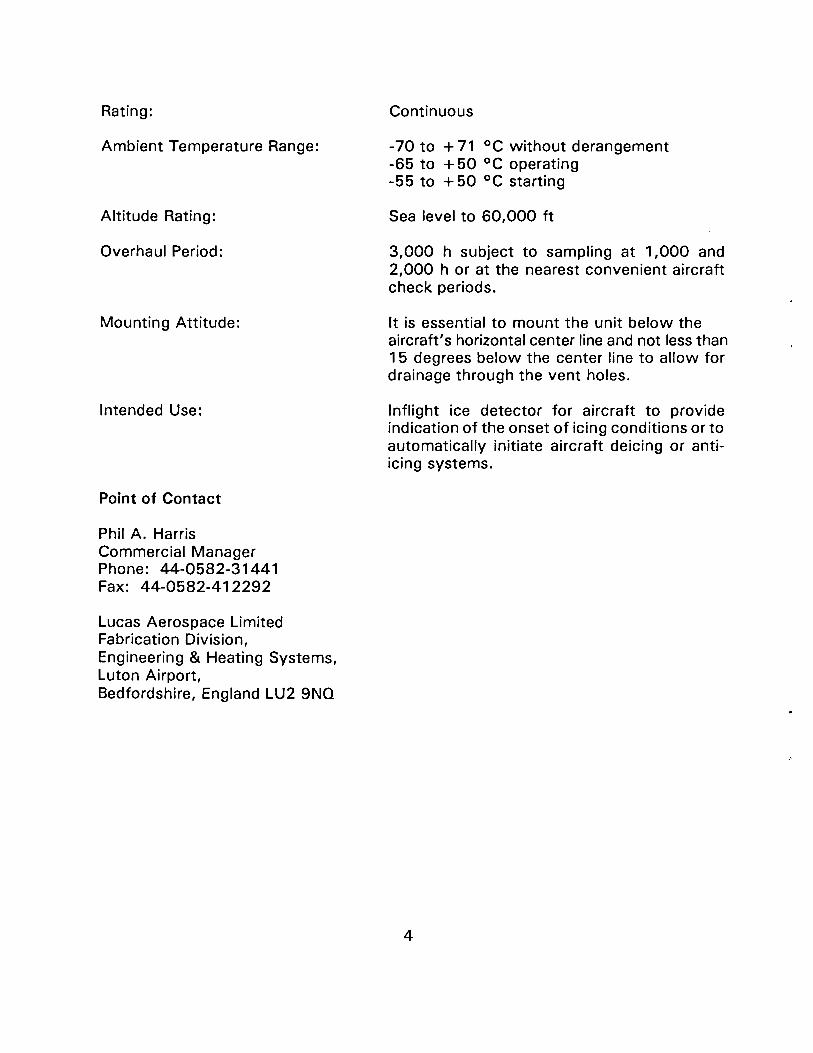
The Lucas Mk 3 series ice detectors consist of a small electrically driven cylinder upon which ice may collect. Part of the cylinder is exposed to the supercooled icing airflow. The presence of ice is detected by a knife-edged cutter that operates close to the rotating cylinder. The ice buildup initiates a shaving action which increases the torque on the electric motor that is driving the cylinder. The torque on the motor under non-icing conditions is negligible. The shaving action however, causes the motor to rotate slightly within its mounting against a spring pressure. This movement of the motor operates a micro-switch, the signal from which may be used to light a warning lamp or other signal or to initiate the operation of a deicing or anti-icing system. This unit is capable of continuous operation or may be switched on or off at the pilot's discretion. The collecting head is self-cleaning and requires no heating.
Data
Weight:
Overall Dimensions:
Fixing Holes:
Design Specifications No.:
Voltage:
Power Consumed:
2. 751b approx.
Length 8. 75 in consisting of a 2.25 in cylinder with a 3.25 in x 0.125 in thick end mounting plate. The rotating cylinder and cutter project 1.25 in from the mounting plate. Two 3-pin polyether- sulphone terminal blocks are fitted to the main body and project 0.66 in from it.
Four 0.1935in diameter holes equally spaced around the end mounting plate at 2. 7in diameter.
N.E.S. 377 Lucas Aerospace Limited.
1 04-126 V 380-420 cps ac single phase. 18-29 Vdc
18 w
3
Rating:
Ambient Temperature Range:
Altitude Rating:
Overhaul Period:
Mounting Attitude:
Intended Use:
Point of Contact
Phil A. Harris Commercial Manager Phone: 44-0582-31441 Fax: 44-0582-412292
Lucas Aerospace Limited Fabrication Division, Engineering & Heating Systems, Luton Airport, Bedfordshire, England LU2 9NO
Continuous
-70 to + 71 °C without derangement -65 to +50 °C operating -55 to +50 °C starting
Sea level to 60,000 ft
3,000 h subject to sampling at 1,000 and 2,000 h or at the nearest convenient aircraft check periods.
It is essential to mount the unit below the aircraft's horizontal center line and not less than 1 5 degrees below the center line to allow for drainage through the vent holes.
lnflight ice detector for aircraft to provide indication of the onset of icing conditions or to automatically initiate aircraft deicing or antiicing systems.
4
Motor
Spring . Air Flow
Micros witch
Figure 1 - LUCAS (Mk3)
Normalair-Garrett Limited
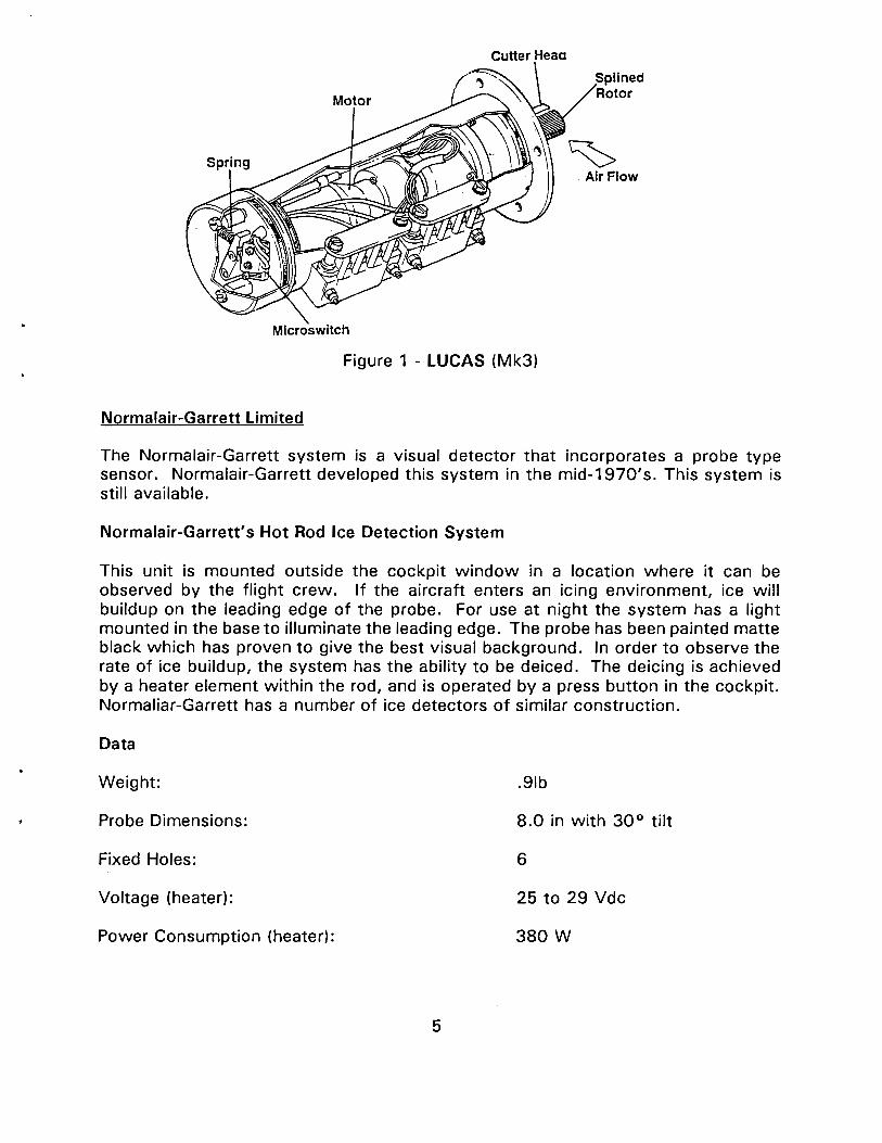
The Normalair-Garrett system is a visual detector that incorporates a probe type sensor. Normalair-Garrett developed this system in the mid-1970's. This system is still available.
Normalair-Garrett's Hot Rod Ice Detection System
This unit is mounted outside the cockpit window in a location where it can be observed by the flight crew. If the aircraft enters an icing environment, ice will buildup on the leading edge of the probe. For use at night the system has a light mounted in the base to illuminate the leading edge. The probe has been painted matte black which has proven to give the best visual background. In order to observe the rate of ice buildup, the system has the ability to be deiced. The deicing is achieved by a heater element within the rod, and is operated by a press button in the cockpit. Normaliar-Garrett has a number of ice detectors of similar construction.
Data
Weight: .91b
Probe Dimensions: 8.0 in with 30° tilt
Fixed Holes: 6
Voltage (heater): 25 to 29 Vdc
Power Consumption (heater): 380 w
5

Point of Contact
Mike Bednall Head of Marketing Phone: 44-0935-75181 Fax: 44-0935-27600
Normalair-Garrett Limited Yeovil, Somerset, England BA20 2YD
Figure 2- NORMALAIR-GARRETT (Hot Rod Ice Detector)
Penny and Giles Avionic Systems Limited
The Penny and Giles system uses a probe type sensor that measures ice buildup in terms of Liquid Water Content (LWC). This system was designed specifically for use on helicopters and is available for all turbine-powered helicopters.
The Penny and Giles Ice Detector
·The Penny and Giles Ice Detector uses an annular jet aspirator powered by engine compressor bleed air to entrain the supercooled water droplets. The water droplets in the ambient air freeze out on a low-thermal-inertia probe in the detector while it is continuously monitored by a solid state photocell. The icing severity, in terms of LWC, is electronically computed from the rate of beam-blockage of the infrared photocell as the probe collects ice. Once iced, the low-thermal-inertia probe is rapidly heated to remove the ice and then cooled to begin another cycle.
6

Data
Liquid Water Content:
Airspeed:
Air Temperature:
Altitude:
Response Time:
Accuracy:
Power: Indicator lamps (28 Vdc) Ice detector ( 115V 400 Hz)
Bleed Air Pressure:
Bleed Air Temperature:
Operating Temperature:
Storage Temperature:
Reliability:
Weight:
Point of Contact
Kevin Rayment Technical Sales Engineer Phone: (0202) 476621 Fax: (0202) 4 70070
7
0 to 2.0 g/m3
0 to 200 kn
0 to -25 °C (32 to -13 °F)
Sea level to 15,000 ft
2 s LWC 1.0 g/m3
±10%
30W 2 W continuous/360 W intermittent
350 ± 100 kPa (50 ± 15 psi) or 170 ± 70 kPa (25 ± 1 0 psi)
operating 50 to 200 °C (120 to 390 °F) max. 200 °C (390 °F)
-57to +71 0°C(-70to +160°F)
-62 to + 85 °C (-80 to + 185 °F)
Electronics: 10,850 h MTBF
Ice detector 0.9 kg (2.0 lbO) Meter 0.34 kg (0. 75 I b)

Penny and Giles Avionic Systems Ltd 1 Airfield Road, Christchurch Dorset BH23 3th United Kingdom
Figure 3 - PENNY AND GILES ICE DETECTOR
Rosemount Incorporated
Rosemount has developed two ice detection technologies that can be used for inflight ice detection. Both the Magnetostrictive and the Heat of Transformation Ice Detection Systems can be used for fixed and rotor wing aircraft and both take the form of a probe type sensor when used for inflight applications. (Although the Model 871 CV and the Model 8738 ice detectors are listed below, Rosemount produces ice detectors for many aircraft locations and applications.)
Magnetostrictive Ice Detection Systems
The sensing probe is driven magnetostrictively to vibrate at its resonant frequency of 40,000 Hz. As the ice detector enters an icing environment, ice collects on the sensing probe. The added mass of the accreted ice causes the frequency of the sensing probe to decrease in accordance with the laws of classical mechanics.
The electronic processor's circuitry utilizes a microcontroller to monitor the probe frequency. When the probe's vibrational frequency decreases by an amount
8

corresponding to a preset thickness of ice accumulation, the ice detector generates an icing signal and deices itself through internal heating elements in both the strut and probe. Deicing takes approximately five to seven seconds. Once deiced, the sensing probe cools, and is ready to sense ice formation again. When ice re-accretes on the sensing probe to the preset ice thickness trip point, another signal will be issued. Should this occur before the previous signal has timed out, the icing signal will be continuous. This cyclic process is repeated as long as the ice detector remains in an icing environment.
Heat of Transformation Ice Detection Systems
The Heat of Transformation Ice Detection System (HOT) uses a patented Thin Film Platinum Resistance Thermometer (TFPRT) technology. Periodically, the TFPRT sensing element is heated with constant power input until a cutoff temperature is reached. Then power to the element is removed. The element cools down and remains at ambient temperature until it is pulsed for the next cycle. During each sensing cycle, microprocessor electronics measure the time between two set point temperatures. When no ice is present on the TFPRT element, the temperature rise is steady and the times will be constant. In icing conditions, ice forms on the sapphire surface of the TFPRT element. When the sensing element is pulsed, the sapphire surface begins to heat up. When the sapphire surface reaches 0°C, any accumulated ice starts melting at the ice-sapphire interfaces. This melting absorbs considerable energy and substantially reduces the rate of temperature rise. After the accumulated ice melts and the water runs off, the rate of temperature rise returns to the some rate as before melting commenced. When the cutoff temperature is reached, power is removed from the sensing element.
To determine if ice is present during the heating cycle, the microprocessor electronics monitor the time interval required to pass through two set point temperatures. If the time interval required to pass through both temperatures is greater than the time interval in non-icing conditions, then ice is present.
Data (Model 871 CV Magnetostrictive Ice Detector)
Height:
Width:
Depth:
Weight:
Standard Trip Point:
Temperature:
9
4.1 in approx.
3.84 in
3.94 in
2.0 lb max.
Nominally 0.020 in ice thickness
-55 to + 70 oc

Altitude:
Duration of Icing Signal:
Power Requirements:
Power Consumption:
Data (Model 8738 Heat of Transformation Ice Detector)
Height:
Width:
Weight:
Temperature:
Altitude:
Humidity:
Icing Signal:
Power Requirements:
Point of Contact
Richard Feely Marketing Engineer Phone: (612) 892-4381 Fax: (612) 892-4430
Rosemount Incorporated Aerospace Division 143000 Judicial Rd. Burnsville, MN 55337
10
-1000 to + 50,000 ft
60s ± 10 s
28 Vdc and/or 11 5 Vac, 400Hz per MIL-STD-704A
350 W max.in deicing mode 15 W max.in sensing mode
8.9 in
2.25 ±0.25 in
1.5 lb approx.
-67 to + 160 °F
80,000 ft max.
1 00% rh at 11 0 ° F
60s ± 10 s
28 Vdc ± 4 Vdc (heater) 5 W (idle and detection) 400 W (deicing mode)

Figure 4- ROSEMOUNT (Model 871 CV Magnetostrictive Ice Detector)
Sunstrand Corporation
The Sunstrand Ice Detection System use a probe type sensor and can be used on fixed wing and rotor wing aircraft.
Sunstrand Data Control's Ice Detector System
The Sunstrand system uses a mounted probe with a sensing surface facing the airstream. Beta particles are released from a Strontium 90 Radiation Source and are collimated by a specially shaped window in the probe housing. These particles pass across the sensing surface to a Geiger-Muller tube. High voltage is applied to the Geiger-Muller tube to enable it to detect the radiation emitted by the Strontium 90 source. Ice accretion on the probe decreases the beta particles detected by the tube. When the particle count drops below a pre-set level, a pulse rate discriminating amplifier energizes an icing signal visible to the flight crew. At this time a heater inside the probe is activated, the ice is removed from the probe, and the probe is ready to begin another icing cycle.
In the event of an overheat, the second relay is energized, breaking the power to the heater. A lock-on circuit keeps the second relay energized until the system can be reset.
11

Data (Ice Detector Probe)
Height:
Length:
Width:
Weight:
Radiation Source:
capsule
Structural Integrity:
Point of Contact
Greg Francois Marketing Product Manager Phone: (206) 885-8576 Fax: Message Return (206) 885-2061
Sunstrand Corporation Sunstrand Aerospace 15001 N.E. 36th Street P.O.Box 97001 Redmond, Washington 98073-9701
SOURCE ---+11
5.35 in max.
2.75 in max.
2.50 in max.
Less than 1 lb
50 microcurries of Strontium in hermetically sealed
Will withstand 1450 ft•lb ice ball impact
SHAPED PROBE WINDOWS /'}--::r.-f--SENSING SURFACE
SETA PARTICLE BEAM
PROBE
POWER I
SUPPLIESbl
115V 400Hz
I
OUTPUT SIGNAL
RELAY
L ________ _j PULSE RATE OISCRIMINA TING AMPLIFIER
CONTROLLER
Figure 5 - SUNSTRAND ICE DETECTOR
12

Vibro-Meter Corporation
Vibro-Meter's Ice Detection Sensor can be used on fixed and rotor wing aircraft. This probe has a flush-mounted sensor that is placed in the direct airflow to detect an icing environment. (Although the Model EW134 will be described below, the technology may be configured to many shapes.)
Vibro-Meter Model EW134
The Vibro-Meter method is based upon the principle that the resonant frequency of a solid body will change with a change in mass or stiffness. Ice is detected using a continuously vibrating sensor diaphragm which is forced into oscillation at its resonant or natural frequency by a piezoelectric material. The piezoelectric material is driven by an electronic oscillator. The resonant frequency is ultrasonic (above 70 kHz) and the maximum oscillation amplitude very small (under 1 micrometer) so that effectively there are no moving parts.
Ice accretion on the sensor diaphragm increases its stiffness and mass, hence increasing the natural frequency. Water or liquid contaminants increase the sensor diaphragm mass without increasing the stiffness thus decreasing the natural frequency. This sensor is designed to extend into the free stream air flow.
Data
Height: Probe Electronics housing
Width:
Weight:
Material: Probe and sensor All other external parts
Temperature: Operating Survival
Altitude:
13
3.149 in 5.511 in
3.5 in approx.
1.55 lb
Stainless steel Aluminum alloy with yellow Alodine coating
-67 to + 160 °F -7 6 to + 1 8 5 ° F
80,000 ft max.

Humidity:
Shock:
Power requirements:
Point of Contact
Charles Witt Vice President Phone: (310) 320-8410 Fax: (310) 618-9670
Vibro-Meter Corporation 22109 South Vermont Ave. Torrance, CA 90502
AIRFLOW . '::/!;;
mounting flange
electronics housing ~
100% rh at 110 °F
Saw tooth pulse 20 g, 11 ms duration, 6 shock axis
11 5 Vac ± 15 Vac, 400 Hz generally to RTCA D0-1 60C or specific user requirements
Figure 6 - VIBRO-METER (Model EW134)
14

PROMISING TECHNOLOGIES (lnflight)
Simmonds Precision
Simmonds Precision has developed two separate ultrasonic Ice Detection and Measuring Systems (IOMS). These systems use flush-mounted sensors and can be used on rotor or fixed wing aircraft with use of as many as eight sensor heads.
Simmonds Precision Ultrasonic Ice Presence Measurement System
This system uses a pulse-amplitude technique. A piezoelectric ceramic crystal (PCC) acts as a transmitter and launches an ultrasonic pulse through a delay line to the surface being monitored. After initial excitation, the PCC acts as a receiver and detects an echo returning from the surface. The delay line guarantees that the PCC has recovered from the initial excitation before it receives the returning echo. When an air interface is present at the surface being measured (no ice), a maximum amount of energy is reflected. When ice is present, approximately 30 percent of the transmitted ultrasonic energy propagates in the ice, thus reducing the level of the reflected signal the PCC receives. This level reduction provides an indication of the presence of thin ice layers. Once the ice has exceeded the threshold thickness, the sensor continues to detect the presence of ice regardless of the accretion of additional ice.
Simmonds Precision Ultrasonic Ice Thickness Measurement System
This system uses a pulse-echo technique. There are two PCC's. One acts as a pulse transmitter, and the other acts as a pulse echo receiver. The signal conditioner sends a high-frequency excitation signal to the first PCC, which transmits an acoustic pulse toward the sensing surface. Either the sensing face or the surface of the ice, when ice is present, reflects the acoustic pulse. The second PCC receives the returning echo. The signal conditioner measures the transit time between excitation and receipt of the returning echo, thereby determining the amount of accumulated ice.
Data (Ice Presence Measuring System)
Ultrasonic Sensor
Size: 1 . 3 55 in x 1 . 1 00 in
Weight: 0.14 lb
Power requirements: 28V; 5W (when deicing heater is activated)
Temperature ranges: -55 to + 200° C
15

Reliability: 4 72,000 h MTBF
Signal Conditioner
Length: 8.10 in
Width: 4.50 in
Height: 1.69 in
Weight: 2.5 lb
Power requirements: 28 V; 5 W
Temperature ranges: -55 to + 74 °C (commercial) -55 to + 95 °C (military)
Reliability: 51,000 h MTBF
System Accuracy:
0.010 in ± 0.005 in (ice detection mrnrmum thickness threshold) for temperatures of -20 to 0 °C and liquid water content levels between 0.2 to 2 g/m3.
Data (Ice Thickness Measuring System)
Ultrasonic Sensor:
Length:
Width:
Weight:
Power Requirements:
Temperature Ranges:
Reliability:
Ice Thickness Measuring Range:
Accuracy:
16
1.0 in
0.6 (or per customer specifications)
Less than 0.15 lb
7 W (for heater, when included)
-55 to + 150 °C (operating) -55 to + 300 °C (non-operating)
100,000 h MTBF
0.025 in to 0.150 in
Set point ± 0.005 in
Signal Conditione-r:
Length:
Width:
Weight:
Power Requirements:
Temperature Ranges:
Reliability:
Point of Contact
Derek Van Dyke Director Commercial Marketing Phone: (802) 877-4421 Fax: (802) 877-3996
Simmonds Precision Aircraft Systems Division Panton Road Vergennes, VT 05491
17
7.0 in
4.5 in, 2.5 in thick (or per customer specifications)
2.5 lb
28V; 5W
-55 to + 75 °C (commercial) -55 to + 95 °C (military)
31,000 h MTBF

ONGROUND ICE DETECTION SYSTEMS
Finn air
Fin nair has developed a clear ice detector to aid in the visual inspection of upper wing surfaces for ice buildup.
Finnair Clear Ice Detector
These indicators have been designed for clear ice inspection during the pilot's walk around check. If no clear ice or a negligible amount of ice exists, five equal fivemillimeter-wide stripes which are painted alternating red and yellow are visible to the observer. If clear ice exists, one or more of the strips will not be visible to the observer. Thickness of clear ice can be estimated knowing that each stripe is five millimeters thick.
Data
Height:
Length:
Weight:
Materials:
Point of Contact
Jouko Haime Manager Project Engineering Phone: (358-0) 8286192 Fax: (358-0) 8186797
Finnair Helsinki Airport 01530 Vantaa Finland
25 mm (5 sections 5 mm each)
75 mm
75 g
2.03 mm thick cres steel 321
18

KELTAIN£N;y£LLOW) \
I \
\
fPUNAINEN I (R£0)
I
I I
I -----~- ____ ;___ __
~: ------- ----- -~ ___________ I f-- --- ~-
Figure 7 - FINNAIR ICE DETECTOR
McDonnell Douglas Corooration
FWD
I I
McDonnell Douglas has developed the use of painted stripes to detect clear and rough ice.
McDonnell Douglas Clear Ice Detector
This system uses non-slip black painted stripes that are installed on the upper wing surface. The physical check for wing upper surface ice may be made with an inspection pole. The wing surface is rough where stripes are painted black, and smooth between the black paint stripes. When the wing's surface in the area of the black painted stripes has a consistent texture, either rough or smooth, ice may be present and further checking of the wing surface is required. Only the rough-smoothrough contrast felt with an inspection pole indicates no ice is present.
Data
Stripe Size: 3 in
Over All Length: 5 ft
Over All Width: 4ft
19

Point of Contact
Lars Rosenbiad Senior Engineer Phone: (31 0) 593-6931 Fax: (310) 593-7352
McDonnell Douglas 3855 lakewood Blvd. Mail code 36-50 long Beach, CA 90846
Figure 8 - McDonnell Douglas Clear Ice Detector
O'Connor ladder Company Inc.
The O'Connor ladder Company manufactures a ladder that is designed specifically to aid in the visual detection of ice that is attributable to cold soaked fuel on the surface of aircraft wings.
The O'Connor 412-9-SP Aircraft ladder
This ladder was designed primarily for wing ice inspection on the MD 80 aircraft, however it may be used for other tasks. The ladder is made from aluminum with curved rubber pads where the ladder comes in contact with the wing surface. The ladder rests on the leading edge of the wing at a 20° slope. The ladder is designed to be used either alone to aid in the touching of airfoil surfaces, with other visual ice detection devises, or with user supplied ice detection devices. American Airlines has developed a pole that is used in conjunction with this ladder. This pole is seven feet
20

in length, is made from half inch schedule 40 PVC pipe, and has a hand grip at one end. This pole is attached to the ladder and can be detached to inspect the icing tufts on the upper wing surface.
Data
Weight:
Over all Length:
Over all Width at Top:
Over all Width at Bottom:
Point of Contact
Vart Barsamian President Phone: (818) 579-0127 Fax: (818) 579-7268 Outside Calif: 1-800-367-1579
The O'Connor Ladder Company Inc. 1703 Floradale Ave. South El Monte, CA 91734
30 lb per unit
1 04 in (available in longer lengths)
19.5 in
28.5 in
Figure 9 - O'CONNOR LADDER COMPANY (Model 412-9-SP) (pole not shown)
21

Rosemount Incorporated
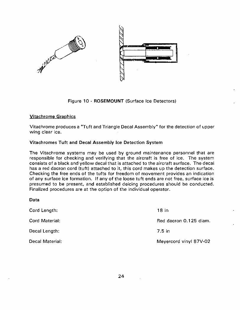
Rosemount offers two surface-mounted ice detection technologies. The Rosemount Surface Solid-State Ice Detector (SSSID) is based on the TFPRT technology. The Rosemount Magnetosrictive Surface Sensor utilizes a magnetostrictive oscillator (MSO) circuit to detect the accretion of ice on a diaphragm mounted flush with the surrounding surface.
Magnetostrictive Ice Detection Systems
The Rosemount magnetostrictive surface ice sensor detects the accumulation of ice on a flush-mounted sensing surface. The sensing surface has a thin annular ring diaphragm section. The center of the sensing surface is rigid and is attached to a standard Rosemount magnetostrictive sensor tube. This tube expands and contracts under the influence of a varying magnetic field. The metallurgical properties of the sensor tube have been selected to minimize the effect of temperature on the overall accuracy of the sensor. The magnetic field is provided by a drive coil surrounding the lower half of the tube. An MSO circuit is created with the addition of a pickup coil and an operational amplifier. The axial movement of the tube, which results from the activation of the drive coil, causes a current to be induced in the pickup coil. This current from the pickup coil drives the operational amplifier which provides the signal for the drive coil.
In an icing situation, ice will accrete on the sensing surface. In accordance with the laws of classical mechanics, a layer of ice across the thin annular ring diaphragm section will increases the stiffness of the system, and therefore the natural frequency will increase, in direct proportion to the thickness of ice present. The accumulation of .010 inches thickness of ice on the sensing surface will cause the vibrational frequency of the system to increase by approximately 330Hz. When the electronics, which constantly monitor the sensor's frequency, measure the frequency change corresponding to the preselected ice thickness accumulation, an icing signal is issued.
Heat of Transformation Ice Detection Systems
The Rosemount SSSID uses a TFPRT element to sense the presence of icing conditions and/or snow accumulations. The SSSID uses microprocessor-based electronics with the ability to modify measurement parameters to fit the individual applications. The sensitivity of the sensor can be adjusted for varying ice thickness trip points and possibly differentiation between "wet" and "dry" snow measurements.
The TFPRT element consists of a thin film of platinum deposited on one side of a sapphire substrate. Supercooled water droplets and/or snow accumulate on the sapphire surface providing the basis for detection. The resistance element of the TFPRT functions both as a temperature sensor and a heater. Periodically, the element is heated by pulsing approximately three watts of power through the platinum grid causing the element's temperature to rise at a rate of 500 °F per second. Once the
22

cut-off temperature is reached, the power input ceases until it is pulsed for the next cycle. During each sensing cycle, microprocessor electronics measure the time between two set point temperatures. When no ice or snow is present on the TFPRT element, the temperature rise is steady and the time duration between cycles is constant.
When the sensor is pulsed during ice or snow conditions, the ice or snow accumulated on the sapphire surface will start melting once the sensor temperature reaches 0 °C. This melting absorbs considerable energy and substantially reduces the rate of temperature rise during the frozen to liquid water phase transition period. After the ice or snow is melted, the rate of temperature rise returns to the same rate as before melting commenced. To determine if ice or snow is present during the heating cycle, the microprocessor electronics monitor the time interval required for the heated element to pass through two set temperature points. The sensor's temperature quickly rises to the ice melting point, passing through the first temperature and triggering the ice counter. The TFPRT element temperature plateaus near 0 °C while the heat melts the accumulated ice. After the ice is completely melted, the element temperature quickly rises and passes through the second set point temperature, shutting off the internal ice counter. If the time interval required to pass through both temperatures is greater than in a non-icing conditions, then ice or snow is present.
Data
Both the Magnetostrictive Surface Ice Detection (Models 870) and the Heat of Transformation (Models 875) Ice Detection Systems are customized for each specific application.
Point of Contact
Richard Feely Marketing Engineer Phone: (612) 892-4381 Fax: (612) 892-4430
Rosemount Incorporated Aerospace Division 14300 Judicial Rd. Burnsville, MN 55337
23
~ ~ " ~
~ -v I ,.....
"" ' '"'Il'-\ ~ ~ I>
Figure 10 - ROSEMOUNT (Surface Ice Detectors)
Vitachrome Graphics
Vitachrome produces a "Tuft and Triangle Decal Assembly" for the detection of upper wing clear ice.
Vitachromes Tuft and Decal Assembly Ice Detection System
The Vitachrome systems may be used by ground maintenance personnel that are responsible for checking and verifying that the aircraft is free of ice. The system consists of a black and yellow decal that is attached to the aircraft surface. The decal has a red dacron cord (tuft) attached to it, this cord makes up the detection surface. Checking the free ends of the tufts for freedom of movement provides an indication of any surface ice formation. If any of the loose tuft ends are not free, surface ice is presumed to be present, and established deicing procedures should be conducted. Finalized procedures are at the option of the individual operator.
Data
Cord Length: 18 in
Cord Material: Red dacron 0.125 diam.
Decal Length: 7.5 in
Decal Material: Meyercord vinyl 87V-02
24

Point of Contact
David MacDonald Aerographics Account Manager Phone: (310) 692-9200 Fax: (31 0) 692-9055
Vitachrome Graphics 11517 Los Nietos Road Santa Fe Springs, CA 09670
AREA Of EASY ACCESS fOR PHYSICAL CHECK BY HAND TOUCH
- SH Kcw•l2168
WINO LOCATIONS OF CLEAR ICE FORMATION
Figure 11 - VITACHROME (Tuft and Decal)
Wahl Instruments Incorporated
The Wahl systems uses an infrared thermometer gun to detect the presence of ice on an aircraft.
Wahl Heat Spy
The Wahl system is based on the principle that all solid objects emit infrared energy above absolute zero. The Heat Spy directs this energy, by means of fixed focus optics, to a sensitive detector. The energy is amplified and processed by the computer to give temperature readings in°F or °C. To use the Wahl system to detect ice it is necessary to have a bare aluminum surface and a painted aluminum surface in close proximity to each other. The temperature is take from both areas of aluminum. If there is no ice present, the Heat Spy senses the infrared energy of the
25

atmosphere as reflected by the unpainted aluminum. The painted aluminum, however, does not reflect in the infrared range. Therefore the energy detected is the energy emitted by the painted surface, giving the temperature of the surface, not the atmosphere. This means that if no ice is present the two readings may differ in temperature (greater than 10 °F). However, if there is ice present the infrared signal will not be reflected from the bare aluminum surface and will provide the temperature of the surface. If readings from the bare aluminum surface and the painted aluminum surface are similar (closer than 5 °F) and both temperatures are below 32 °F, then ice is present.
Data (Model DHS-24X)
Temperature Range:
Accuracyat77 °F ±5°:
Ambient Operational Temperature:
Response Time to 95% of Reading:
Target Size at Focal Point:
Practical Working Distance:
Sighting System:
Operating Time Per Battery:
Weight:
Point of Contact
Herm Rudman Western Regional Manager Phone: 1-800-421-2853 Fax: (213) 670-2840
Wahl Instruments, Inc. 5750 Hannum Avenue Culver City, CA 90231
0 to 1000 °F
±0.3% FS
25 to 125 °F
1 s
1 in diam. at 2 ft
0 to 40ft
Enclosed Sight or Laser
40 h (Laser 5 h)
2.2 lb
26

Figure 12 - WAHL (Heat Spy)
27

PROMISING TECHNOlOGIES (Onground)
Airborne CCTV
The Airborne system is an infrared video wing ice detector. Airborne has used this base technology for detection of fires in the cargo area and in passenger cabin security applications.
Airborne CCTV Infrared Video Wing Ice Detection System
The Airborne system is a self-contained Closed Circuit Television system based on Silicon (Si) Charge Coupled Device (CCD) image technology. The color CCD cameras have a spectral response of ultra-violet through near infrared (IR). The system consists of six line Replaceable Units (lRUs) that are interconnected. The system utilizes near infrared spectrum illumination (.9 micron wavelength) which is directed toward the upper wing surface. The IR is reflected by the subject surface, detected by a silicon chip CCD television camera, and displayed as a black and white image on a cockpit mounted lCD display. This image provides a clear "go/no go" indication. An optical filter switching device permits the camera to operate in the visual light spectrum as well and provides a full color display. The Monitor Display Unit utilizes a seven inch LCD display and provides a menu-driven display to select and view cameras and adjust system parameters.
Each Camera Head Unit has an associated Camera Control Unit (CCU). The CCU translates the video signal from the CCD camera into a usable composite video signal. The CCU also contains camera location identification data and BITE logic, and transmits this data along with the video signal during the vertical interval to the Central Processing Unit. The proposed installation would have the camera mounted in the fuselage wall looking through a 1.5 inch circular window down at the wing surface. The optics provide a field of view from approximately .5 square ft to the entire upper wing surface.
Data
Camera Size:
Camera Weight:
Power Requirement:
28
Less than 1 in3
90 g approx.
< 35 W during system operations < 5 W in standby mode

Total System Weight:
Point of Contact
Thomas D. Henderson President Phone: (714) 263-5750 Fax: (714) 757-0705
Airborne CCTV 4220 Van Karmen Ave. Newport Beach, CA 92660
Bolvad Communications
14.3 lb (not including interconnect cables)
The Bolvad system is a hand held unit which is used by touching it to the surface to be tested.
Bolvad IDSS-1
The IDSS-1 system consists of a custom made sensor which detects the presence and thickness of ice as soon as the sensor touches the surface. It operates by measuring the travel of the tip. The electronic module obtains the readings, analyzes them against the preset values, displays them, and stores them for future tracking. Ice thickness measurements of up to 0.002 inch resolution are detected. By touching the surface, the operator obtains positive indication of ice buildup and its thickness. The IDSS-1 system stores all the readings. At the end of the inspection, the readings could be down-loaded to a centralized system for diagramming, further analysis, or verification. Set points can be securely programmed in as well. All readings are stored in non-volatile memory even when the primary power is removed.
Data
Supply Voltage: 115 Vdc, 0.5 W
Operating Voltage: 15Vdc,0.5A
Operating Temperature: -25 to 65 °C
Storage Temperature: -40 to 80 °C
Maximum Ice Thickness: 0.4 in
Accuracy: 0.002 in
29

Weight: sensor meter
Warmup Time:
Maximum Surface Test Time:
User Memory Capacity:
Program Memory Capacity:
Minimum Number of Readings Stored: non-volatile memory
Maximum Number of Readings Stored:
Point of Contact
David Boyarsky Phone: (609) 428-4315
Bolvad Communication 139 Ashley Court Cherry Hill, NJ 08003
FMC Corporation
0.51b 11b
5 min.
2 s
64 kb
32 kb
8000 readings
30,000 readings
The FMC Ice Detection System is an external video system that consists of a special camera, an image processor, and a video monitor.
FMC Ice Imaging System
The FMC camera forms an image of the aircraft which is transformed by the image processor and then displayed as a pseudocolor video image. Distinctive colors highlight patches of ice on the display screen. The system discriminates ice from water by exploiting the natural spectral shift which occurs when water freezes. The spectral signatures (reflectance spectra) of water and ice are not identical, even though both substances appear transparent to the eye. The differences are in the non-visible portions of the spectrum.
30

In the FMC system, specially prepared filters are used in conjunction with panspectral imaging arrays. Each filter is selected to admit light only within a predetermined pass band. Ratios of the reflected energies are made at a large number of points over the electronically sampled image. The ratiometric data are transformed into a displayable image which is used to highlight areas of interest on a conventional video image.
Data
No specific data exists at this time.
Point of Contact
Doug Robertson Engineering Manager Phone: (407) 850-2858 Fax: (407) 857-9180
FMC Airline Equipment Division 7300 Presidents Drive Orlando, FL 32809
lnstrumar Limited
lnstrumar has proposed a system that uses a flush-mounted sensor for use on fixed wing aircraft.
lnstrumar Aircraft Ice Detector
The lnstrumar prototype has a 60 mm diameter and has been designed to measure ice layers from 0.2 mm to 5 mm in thickness. The sensor is constructed of a material with similar thermal and structural properties to those of aircraft wings. The sensor is designed for detection, thickness, and characterization of ice and snow. It will be able to distinguish ice from de/anti-icing fluids, and to provide a measure of the state of the fluids. The sensor establishes electric fields close to its surface with a series of electrodes to measure and identify existing accretions. These fields are characterized by sensor attributes such as the number of electrodes, their size and configuration, sensor material dimensions and electrical properties, electrode drive voltage levels, and operating frequency. The sensor's response to the presence of different surface accretions is modeled by representing the accretion with one or more stratified layers characterized by their respective electrical properties and thicknesses.
31

Data
Maximum Ice Thickness:
Accuracy:
Sensor Head Diameter:
Sensor Mounting:
Operating Temperature:
Storage Temperature:
Sensor Update Time:
Point of Contact
Robert Vivian Vice President of Marketing Phone: (709) 726-8460 Fax: (709) 726-8613
lnstrumar limited P.O. Box 13246 Station 'A' St. John's, Newfoundland, A 18 4A5
32
5 mm
0.1 mm for ice < 1 mm linearly varying to 0.5 mm for ice at 5 mm
60 mm
Flush
-55 to + 85 °C
-65 to + 100 °C
Less than 4 s

COMBINED ONGROUND AND INFLIGHT ICE DETECTION SYSTEMS
Dataproducts New England, Inc.
The Dataproducts system is available in three different sensor forms: probe, remote probe, and flat sensor. This system was designed in 1979 for use on military and commercial aircraft.
Dataproduct's System for Ice Detection
The Dataproducts New England (DNE) system utilizes the unique thermal quality of ice, where 80 calories of heat are required at 0 °C to change one gram of ice into water. A nickel wire that is in-grooved on a narrow cylindrical probe forms the detection surface. A quantity of energy in the form of a short current pulse (every 2.5 seconds) is introduced into a resistance wire that has been wound on the surface of the icing sensor. This causes the wire to increase in temperature at a rate proportional to the energy dissipated by the wire. The increase in temperature in the wire results in a corresponding change in resistance. By measuring the resistance change and knowing the temperature coefficient of the conductor, the increase in wire temperature can be calculated. As ice accretes, the thermal characteristics change and substantially reduce the conductor temperature rise. This difference in thermal characteristics is compared to an internal reference and an icing signal is generated in the cockpit. The signal also can be used to activate the aircraft ice protection system.
The DNE system is equipped with an integral deicing heater to clear the sensor for the next detection cycle. The DNE system has self-test circuitry and programming that may be activated by an external switch to validate the detector system on the ground, or while airborne.
Data (Model 6316-5)
Probe Length: 2.55 in
Ice Warning Point: 0.006 in
Electronic Pulse: Every 2.5 s
Detection Signal: Within 5 s
Reliability: 23,000 hat 100 °C MTBF
Operating Power: 28 Vdc
33

Point of Contact
Bob Freedman Phone: (203) 265-7151 Fax: (203) 265-9101
Dataproducts Corporation Dataproducts New England, Inc. 50 Barnes Park North P.O. Box 30 Wallingford, Connecticut 06492
Figure 13 - DATAPRODUCTS (6316-9)
Vibro-Meter Corporation
The Vibro-Meter Overwing Ice Detection System was designed for fixed wing aircraft. (Although the system described below is for overwing use almost any shape can be realized to accommodate many applications for both inflight and onground operations.)
34

Vibro-Meter Overwing Ice Detector
The Vibro-Meter method of measuring ice is based upon the principle that the resonant frequency of a solid body will alter with a change in mass or stiffness. Ice is detected using a continuously vibrating sensor diaphragm which is forced into oscillation at resonant frequency. The resonant frequency is ultra-sonic and the maximum oscillation amplitude is very small (under 1 micrometer) so that effectively there are no moving parts. Ice accretion on the sensor diaphragm increases both the stiffness and mass, thereby increasing the resonant frequency. (The effect of the increased stiffness is much greater than that of the increased mass.) Water or liquid contaminants increase the mass without increasing the stiffness thus decreasing the natural frequency.
If a predetermined thickness of ice is detected on the surface of the sensor while the aircraft is on the ground then an indication in the aircraft cockpit will alert the flight crew that deicing action should be taken.
Data
Length:
Weight:
Material:
Operating Temperature:
Power Requirements:
Power Consumption:
Point of Contact
Charles Witt Vice President Phone: (31 0) 320-8410 Fax: (310) 618-9670
Vibro-Meter Corporation 22109 South Vermont Ave. Torrance, CA 90502
35
2.71 in
1.03 lb
Corrosion resistant alloy
-67 to + 171 ° F
28 Vdc
Less than . 5 W in flight Less than . 7 W on ground

Figure 14 - VIBRO-METER OVERWING ICE DETECTOR
36

PROMISING TECHNOLOGIES (combined Onground and lnflight)
Ideal Research Incorporated
This Ideal system is intended as an early warning indicator of icing for use on fixed wing aircraft equipped with Hot Wing Deicers. (Although Ideal Research invented and developed the technology, the patents for this system are owned by the University of Maryland Research Foundation.)
Microwave Ice Accretion Measurement Instruments
The Microwave Ice Accretion Measurement Instruments (MIAMI) system uses a microwave transducer that is mounted in the wing's leading edge or other aircraft part flush with the surface being monitored. The transducer appears as a small white rectangular window conforming to the shape of the aircraft surface. The window is transparent to low levels of microwave energy which pass through the window. The presence of ice (0.003 inches) causes a shift in the resonant microwave frequency of the transducer. This initial shift is detected by a microprocessor-controlled system which then generates the signals required to illuminate the annunciator panel. The microprocessor continues to monitor this shift and uses this information to compute ice thickness, icing rate, and change in icing rate. The effect of ice on the transducer is different from other substances such as free water, oil, grease, insects, or other contaminants and can be recognized by the microprocessor.
Ideal Research also proposes two other forms of the MIAMI system. The MIAMI-PB is a flush-mounted system that is placed under a Pneumatic Boot Deicer. The MIAMIUS is designed for use with unprotected aircraft surfaces.
Data (MIAMI-HW)
Weight: Less than 3 lb
Power Requirements: 6 W at 28 V
Minimum Ice Thickness: 0.003 in
Maximum Ice Thickness: 0.2 in
Microwave Transducer Temp. Range: Non-operating: -55 to + 235 °C Operating: -40 to +40 °C
Temperature All Other Components: -55 to +85 °C
37

Point of Contact
Bertram Magenheim President Phone: (301) 984-5694
Ideal Research Incorporated 1181 0 Parklawn Drive Rockville, MD 20852
38

RELATED TECHNOLOGIES
Dataproducts Corporation
Dataproduct's meteorological ice detectors employ fundamentally the same probe, sensing techniques, and self-deicing features that are used in aircraft versions.
Dataproducts Meteorological Ice Detectors
This system uses a probe that is oriented vertically, providing omnidirectional exposure of the sensor. The pulse and measurement characteristics of the electronics module have been altered to accommodate ground surface environmental conditions. The sensing probe is placed on top of a smooth aluminum mast which is equipped at the bottom with a thread for attachment to standard pipe. The connections for the sensor wire and the integral deicing heater are provided by a 15 inch pigtail through the pipe fitting.
A nickel wire is placed in grooves around the probe to create the sensing surface. The wire is electronically pulsed every 2.5 seconds. If ice forms on the wire, the electrothermal properties of the wire change as heat generated by the pulse melts the ice. Once ice has been detected, an internal heater is activated to melt the remaining ice.
Data
Size: Probe:
Controller:
Weight:
Power Requirements:
39
16 in length, 3 in diam. (at the base, 1. 38 in sensing surface) 10.7 in length, 9 in width, 6.1 in height
Max. 25 lb
150 W max. input voltage internally selected for 115 Vac, 210 Vac, and 230 Vac.

Point of Contact
Bob Friedman Phone: (203) 265-7151 Fax: (203) 265-9101
Dataproducts Corporation Dataproducts New England Inc. 50 Barmes Park North P.O.Box 30 Wallingford, CT 06492
lnstrumar limited
lnstrumar has developed the IM 101 Ice Monitor to detect conditions of surface ice accumulation.
lnstrumar ModeiiM101 Ice Monitor
The sensor functions through measurement of the surface electrical impedance and temperature of a proprietary ceramic probe. This data is combined to sense the surface condition of the probe. A default icing window is programmed into each device and when the parameters fall within this window, an "icing" signal is triggered. The sensor then initiates an optional self-deicing cycle and/or control signal output. The cycle time between initiating a deicing event and returning to a temperature receptive to icing is typically 5 to 10 minutes depending on ambient conditions.
An RS-232 serial interface is provided for data acquisition and computer-based control. An optional power-line monitor can sense the activity of the internal heater for remote applications where it is unsuitable to run an RS-232 data line. The sensor also provides a low-power relay contact closure output.
Data
Overall Height:
Housing Diameter:
Tip Dimensions:
Probe Tip:
Housing Finish:
40
258 mm
84 mm nominal
9.5 mm x 73 mm
Beryllium oxide with Alumina finish
Anodized aluminum

Weight:
Power Consumption:
Line Requirements:
Probe Output:
Probe Programming Mode:
Deicing Cycle Time (typical):
Programmable Sensitivity:
Operating Temperature:
Storage Temperature:
Point of Contact
Robert Vivian Vice President of Marketing Phone: (709) 726-8460 Fax: (709) 726-8613
lnstrumar Limited P.O. Box 13246 Station 'A' St. John's, Newfoundland, A 1 B 4A5
Normalair-Garrett Limited
1.5 kg
6 W (idle) 0-1 00 W heater power
110/220 Vac, 50-60 Hz
Relay closure and RS-232
Terminal keyboard entry; automatically prompts user on power up for changes in probe parameters.
5-10min.
0.1-1mm at -1 °C
-40 to +50 °C (detection inactive below -20°C)
-50to +85 °C
The Normalair-Garrett system is comprised of a humidity and temperature sensor and a signal conditioner and power supply unit.
41

Normalair-Garrett Humidity Detection System.
The sensing unit is comprised of a plastic wafer with an electrically conductive surface and a non-conducting substrate. A thermistor mounted integrally with the sensor provides temperature compensation. The conductive surface of the sensor responds to changes in humidity and the output passes to the signal conditioner unit. If the relative humidity is outside preset limits a relay is energized to provide a warning signal.
Data
Size: Sensor: Signal conditioner/power supply:
Power Requirements:
Consumption (steady state):
Temperature Range: Operating: Without derangement:
Humidity Range: Preset: Operating without derangement:
Point of Contact
Mike Bednall Head of Marketing Phone: 44-0935-75181 Fax: 44-0935-27600
Normalair-Garrett Limited Yeovil, Somerset, England BA20 2YD
Rosemount Incorporated
0.38 lb 2.6 lb
11 5 V 400 Hz single phase ac 20 W max.
-10to30°C -60 to 90°C
70% ± 3% rh (adjustable control 100% rh)0-1 00%
Rosemount employs the same operating theory in its meteorological/ground and ground turbine engines that is used in their aircraft ice detectors.
42

Rosemount Ice Warning Systems
The sensing element is an external probe which vibrates ultrasonically in an axial direction at a resonant frequency of 40 kHz. When ice accretes on the probe the frequency of vibration decreases due to mass loading. At a preset frequency shift, an icing signal is automatically activated. Most Rosemount ice detectors are preset to provide a signal which corresponds to 0.020 inches of ice accretion.
Model number 872DE/524AA is designed for ground turbine engines and stationary devices and Model number 872B/524B is used for radar, television, and radio towers and antennas. Both systems use the same ice sensing principle described above.
Data
Model 872DE/524AA Operating temperature:
Model 872B/524B Operating temperature:
Point of Contact
Richard Feely Marketing Engineer Phone: (612) 892-4381 Fax: (612) 892-4430
Rosemount Incorporated Aerospace Division 14300 Judicial Rd. Burnsville, MN 55337
-54° to + 84 °C
-40 to + 1 60 o C
43 *U.S. GOVERNMENT I'RINTING OffiCE: 1993-704-078/80055