façade system trimoterm ftv invisio - ibea.fr invisio/td64_façade syste… · no.64/v-3/10-2011 3...
TRANSCRIPT
Façade System Trimoterm FTV INVISIO
Technical document No. 64/ Version 3 / October 2011

CONTENT
1.0 Technical description of the Facade system with Hidden Fixing - INVISIO [1] 1.1 General [1] 1.2 Panel profile [2] 1.3 Panel Composition [3] 1.4 Technical data [3] 1.4.1 Basic Technical Data [3] 1.4.2 Coatings [4]
2.0 Design Procedure [5] 2.1 Panel Thickness Selection of Trimoterm FTV INVISIO [5] 2.2 Allowed distances and Minimal Bearing Area of the Panel [5] 2.3 The Manner of Fixing [5] 2.3.1 Fixing in Vertical Installations [6] 2.3.2 Fixing in Horizontal Installations [7] 2.3.3 Intermediate Fixing [8] 2.3.4 Edge Fixing [9] 2.3.4.1 Edge Fixing - Vertical Installation [9] 2.3.4.2 Edge Fixing with an HF102 Aluminium Profile - Horizontal Installation [9] 2.3.4.3 Edge Fixing with a Panel Mask - Horizontal Installation [10] 2.3.4.4 Screw Material [10] 2.3.5 Types of Structure or Sub-structures [11]
3.0 Typical details of system INVISIO [12] 3.1 Vertical installation [12] 3.1.1 Connection to the main beam [12] 3.1.2 Extension of a facade [12] 3.1.3 Top End Support [13] 3.1.4 Top End Support with attics [13] 3.1.5 External corner with flashing [14] 3.1.6 Corner with pre-fabricated corner panels [14] 3.2 Horizontal installation [15] 3.2.1 Connection to the main beam [15] 3.2.2 Panel Extension with a Mask [15] 3.2.3 Edge Fixing with an HF102 Aluminium Profile [16] 3.2.4 Attics [18] 3.2.5 Corner finish with corner lining [18] 3.2.6 Corner finish [19] 3.3 Window and other openings [20] 3.4 Curved INVISIO Façade [21] 3.4.1 Panel Curving at the Joint [21] 3.4.2 INVISIO Segment Panels [22] 4.0 Recommendations for installation [23] 4.1 Preparing Element Prior to Installation [23] 4.1.1 Removing Protective Foil [23] 4.1.2 Elements Cutting [23] 4.2 Base requirements and tolerances for Trimoterm FTV INVISIO [24] 4.3 The Installation of Intermediate Support [25] 4.4 Manipulation and lifting panels [26] 4.4.1 Vertical Installation [26] 4.4.2 Horizontal Installation [27]
5.0 Packing, Transport and Storing [28]
6.0 Maintenance of Buildings [28] 6.1 Annual Service Inspection of Façade [28] 6.2 General Recommendations [28]
7.0 Warranty [28]
We reserve the right to make technical changes. Latest version of the document can be found on the website www.trimo.eu.

No.64/V-3/10-2011 1
1
2
3
1.0 TechnicaldescriptionoftheFacadesystemwithHiddenFixing-INVISIO
1.1 General
The INVISIO façade system includes a fire-proof façade panel, Trimoterm FTV INVISIO, with an invis-ible intermediate fixing designed for multi- field installation of panels sized up to 14 m, with no visible intermediate fixing. The final appearance of the façade is uniform with the architecture of clear shapes. The construction is extremely fast and economical, with few fittings and secondary finishing. The intermediate fixing has a high level of load-bearing capacity and utilises the load-bearing capacity of the panel to the fullest, without any weakening caused by fixing. The system is designed for vertical and horizontal installation (Fig. 1 and 2).
Trimoterm panels FTV HL (hereinafter referred as FTV INVISIO) are fixed to the intermediate supports of steel façade constructions or concrete constructions with installed steel profiles by means of a purpose-built line gasket. The line gasket serves to divide the loading capacity to a larger bearing area. The longitudinal edge of the adjacent panel covers the line gaskets and screws of the attached panel in such a manner that they are not visible on the fin-ished façade. The fixing point is shown in cross-section in Fig. 6. The line gasket is attached with a single or dou-ble screw according to the thickness of the sub construction and static conversion.
The INVISIO system of façades ensures excellent technical characteristics, long life span and a high level of crea-tivity in designing the façade. The range of use of the INVISIO facades is extremely wide. They are appropriate for business, commercial, representative and industrial facilities.
Fig. 1: Vertical installation Fig. 2: Horizontal installation
Fig. 3: Fixing in the thick wall construction Figure 4: Fixing in the thin wall construction
2
3
1
1 Panel Trimoterm FTV INVISIO2 Self-tapping screws3 Extension element

No.64/V-3/10-20112
L
MS
123
1 Outside steel sheet (side A)2 Inside steel sheet (side B)3 Core of mineral wool
Fig. 5: Shapes of Trimoterm FTV INVISIO panels
Profile Type Side A Side B
S - profile • •
V - profile (v) • •
V - profile (v2) • •
Smooth (g, G) • •
Micro lined (m) •
Micro lined (m2) •
Micro lined (m3) •
Multi vario (X01) •
Section view of Trimoterm FTV INVISIO panel
side A
side B
Microlined profile (m)
Multi vario profile (X01)
7.5 7.5
Microlined profile (m2)
10 10 201.0
Microlined profile (m3)
15 151.5
30
S - profile (standard profile)
V - profile (v)
V - profile (v2)
6.2
6.2
Smooth profile (G, g)
Shape of profile
1.2 Panel profile

No.64/V-3/10-2011 3
Table 1: Technical data for Trimoterm FTV INVISIO
Technical data INVISIO FTV HL50
FTV HL 60
FTV HL80
FTV HL 100
FTV HL 120
FTV HL 133
FTV HL 150
FTV HL 172
FTV HL 200
FTV HL 240
Panel thickness [mm] 50 60 80 100 120 133 150 172 200 240
Weight [kg/m2] Fe 0,6/Fe 0,6 16.5 17.7 20.1 22.5 24.9 26.5 28.5 31.2 34.5 39.3
U Thermal conductivity [W/m2K] (EN 14509:2006) 0.76 0.61 0.47 0.39 0.32 0.30 0.26 0.23 0.20 0.17
EI fire resistance class (EN 1364-1, EN 13501-2) EI 30 EI 60 EI 90 EI 120 EI 180 EI 240
Combustibility(EN 13501-1) Non-combustible mineral wool core, class A1
Rw Sound reduction [dB][EN ISO 140-3]*
30 32
Panel width [mm] 1000
Panel length [m] up to 14
1.3 Panel Composition
1.4 Technical data
1.4.1 Basic Technical Data
The fire-proof Trimoterm FTV INVISIO panels are composed of two shallow profiled, galvanised and colour-coated steel sheets (0.6 mm or 0.7 mm thick). The sheet metal is glued to the panel core made of non-combustible laminated mineral wool of the A1 (En ISO 11 82) type, which ensures excellent thermal and sound insulation of panels as well as the highest fire resistance. All three layers are bonded to form a composite element (in a thickness of 50 to 240 mm) that fulfils the required load-bearing capacities, tightness and wide construction possibilities.
A polythene foil is glued to the surface of the panels, functioning as protection during handling, transport and mounting. After the mounting is completed, the foil is removed. The length of the panels is up to 14 m.

No.64/V-3/10-20114
1.4.2 Coatings
The sheet metal is coated with an anti-corrosive protection of 275 g of hot zinc layer (Zn)/m2 (EN 10142, EN 10147) and a protective colour applied with the “Coil Coating” procedure. The protective colour can be selected according to the use and level of protection. The coating thickness limits the maximum thickness of the sheet metal. Types of protection and individual thicknesses of sheet metal are shown in Table 2.
The surfaces must be checked and cleaned at intervals, depending on the level of air pollution and aggressiveness, within the framework of regular maintenance and in accordance with the instructions on maintenance, or at least once a year.
Table 2: Basic properties of an individual type of protection
Note: •••• suitable without reservations ••• very suitable •• suitable • suitable with reservations/contact Trimo - unsuitable
* Temperature must not fall below condensation point when cleaning. See table for details: Condensation point temperature is shown at specific ambient temperature and relative humidity. In case of cooling down, working temperature must be 3° C above condensation point. ** Corrosion categories are defined by climatic conditions of external and internal building environment. Standard external climatic conditions: C1, C2, C3, C4, C5-M and C5-1. Example: outside atmosphere C3 --> steel sheet of corrosion category RC3 or RC4 is selected.*** Recommended for use North of 45th parallel latitude and maximum temperature 70° C.
TYPE OF CORROSION PROTECTION SP SP PVDF PVDF+ PUR PVC(P) PVC+F
Corrosion classification [DIN 55928-8] II III III III III III III
Total organic thickness (my) [EN 13523-1] 15 25 25 35 50 max. 175 max. 175
Maximum steel sheet thickness [mm] 0.7 0.7 0.7 0.7 0.7 0.6 0.6
Corrosion resist-ance category **
External EN 10169-2 — RC3 RC3 RC4 RC5 RC5 —
Internal EN 10169-3 CPI2 CPI3 — CPI4 CPI5 CPI4 CPI5
Type
s of
ou
tdoo
r at
mos
pher
e /
cor-
rosi
vity
cat
egor
y [E
N10
169
-2]
Rural - normal C2 — ••• ••• ••• ••• •*** —
Urban and industrial C3 and C4 — •• ••• •••• ••• •*** —
Marti-tame
0 < 10 km from sea C5 - M — — •• ••• ••• •*** —
10 < 20 km from sea C4 — • •• ••• •••• •*** —
Severe industrial C5 - I — — — • • •*** —
Type
s of
indo
or a
tmos
pher
e /c
orro
sivi
ty c
ateg
ory
[EN
1016
9-3
]
Non-corrosive atmosphereRoutine upkeep - normalLow humidity
Ai1-40°Cà25°C0% - 40%*
•• •• — •• ••• •• •••
Non-corrosive atmosphereRoutine upkeep - normalMedium humidity
Ai20°Cà25°C
40% - 60%*•• •• — •• ••• •• •••
Non-corrosive atmosphereNon-intensive cleaningHigh humidity
Ai30°Cà25°C
60% - 80%*— • — •• ••• •• •••
Slightly corrosive atmosphereNon-intensive cleaningHumid (risk of condensation)
Ai40°Cà30°C60% - 80%*
— — — •• ••• •• •••
Corrosive atmosphereIntensive cleaningVery humid (frequent risk of condensation)
Ai50°Cà35°C
80% - 90%*— — — — — — ••
Highly corrosive atmosphereHighly intensive cleaningSatureted (permanent risk of condensation)
Ai60°Cà40°C
90% - 100%*— — — — — — —
Temperture resistance (°C) +70 +80 +110 +110 +110 +70 +70
UV resistance category [EN 13523-10] — Ruv3 Ruv4 Ruv4 Ruv4 Ruv2 —
Flexibility •• •• ••• •••• •••• •••• ••••
Staining resistance •• ••• •••• •••• •••• •• ••••

No.64/V-3/10-2011 5
2.0 DesignProcedure
2.2 Allowed distances and Minimal Bearing Area of the Panel
The façade element requires a static evidence of the load-bearing capacity in accordance with EN 14509:2006 or national provisions. The conversion must be performed for a concrete installation and loads. To help you with the selection and design of the façade, a Table of allowed distances has been produced, listing the allowed distances and minimal bearing areas for construction. The allowed distances are listed in the annex of the instructions and are intended for informational purposes. The detailed distances between supports need to be calculated individually for each facility. The conversion of allowed distances is available on the Trimo Technical Service web site.
The main factors for determining the fixing are:1. Wind load: - Basic wind load, - Height of the façade above the terrain, - Position on the façade (edge areas).2. Temperature load: - Panel colour (group I, II or III).3. Static system of panel laying: - Single-field, double-field, multi-field.4. The manner of panel mounting - Horizontal installation, - Vertical installation, - Single-field, double-field, multi-field.
Considering the listed factors, the façade can be subjected to various loads. The allowed distances or the sub construction and the fixing manner must be adapted to the loads.
2.1 Panel Thickness Selection of Trimoterm FTV INVISIO
Based on the investor’s wish, the Trimoterm FTV INVISIO panel, fixing and the required sub construction for fixing is determined in accordance with the legislation.
The basic information required for designing is:1. Information on the facility (location, type of the facility, purpose of the facility, desired appearance of the facility, thermal insulation, etc.)2. Information on the façade element: - Panel thickness - Type of sheet metal and panel (sheet metal thickness and colour) - Modular width - Panel length3. Determining the type of mounting and execution of details
On the basis of input data, the following is determined:1. The load on the panel and sub construction2. Sub construction and type of fixing: - Allowed distances or the range of the panel - Minimum bearing area of the panel - Fixing
2.3 The Manner of Fixing
Fixing of the FTV INVISION panel is a combination of edge and intermediate fixing. The intermediate fixing is the same for horizontal and vertical installation. Edge fixing depends on the manner of installation and comes in various forms.

No.64/V-3/10-20116
Fig. 7: Vertical installation with edge fixing
Fig. 6: Vertical installation without edge fixing
2.3.1 Fixing in Vertical Installations
Vertical mounting is performed on the prefabricated foundation girder to which a panel is positioned. The weight of the panel is transferred on the foundation girder. Two types of fixing are used: vertical mounting with edge fixing (Fig. 6) and vertical mounting without edge fixing (Fig. 7). In the system without edge fixing, the minimum distance of fixing in the joint must be at least x = 600 mm from the edge in order to ensure appropriate load-bearing capacity of fixing in the joint. In that case, the load-bearing capacity of the panel in an overhanging position must be checked statically.
1 Panel Trimoterm FTV INVISIO2 Self tapping screw3 Expansion element
1
3
2
Fixing to an intermediate support
21
3
4
2
Edge fixing
Fixing to an intermediate support
Edge fixing
1 Panel Trimoterm FTV INVISIO2 Self tapping screw with washer3 Self tapping screw without washer4 Expansion element

No.64/V-3/10-2011 7
2.3.2 Fixing in Horizontal Installations
Fig. 9: Horizontal installation with HF102 fixing profile
1 Panel Trimoterm FTV INVISIO2 Self tapping screw without washer3 Self tapping screw with washer 4 Expansion profile5 Rectangular tube6 Installation Z profile7 Aluminum fixing profile HF102
Two basic types of fixing or transversal extension of the façade for horizontal installation are used: horizontal installation with mask (Fig. 8) and horizontal installation with fixing by means of Al profile with the HF102 label (Fig. 9). In the case of façade extension with mask, the edge panel is attached with two screws on each side. Edge screws transfer the weight of the panel and wind load.
Fig. 8: Horizontal instillation with mask
1 Panel Trimoterm FTV INVISIO2 Self tapping screw without washer3 Self tapping screw with washer4 Expansion element5 Panel mask
The façade extension is performed with a HF102 fixing profile, which has a function of edge fixing as well, but only for wind load. In order to transfer the load of the panel’s weight, the back sheet metal of the panel must be additionally screwed to prevent the settlement of the entire façade. The fixing of interior sheet metal is performed in various manners described in Chapter 4.3.
Edge fixing
Fixing to an intermediate support
42
3
1
5
Edge fixing of back steel sheet
Fixing to an intermediate support
42
71
Spacer profile
5
63

No.64/V-3/10-20118
1 Self tapping screw without washer2 Expansion element
1 Panel Trimoterm FTV INVISIO2 Self tapping screw without washer3 Expansion element4 Line gasket
In general, the minimum required bearing area on the intermediate support for an appropriate positioning on a sub construction is 60 mm or is determined by static conversion (Fig. 12). In the case of fixing for a thick wall sub construction, the line gasket is attached with two screws. In this case, the minimal required surface of the sub construction is 80 mm or is determined by static conversion (Fig. 13). Number of screws is determined calculation of statics. It is dependent on the load and the thickness of the sub-structure.
2.3.3 Intermediate Fixing
Intermediate fixing is a combination of screw and expansion element (Fig. 10, 11) and a (sub) construction. The line gasket takes over one load direction through the screw and the sub construction takes over the other load direction. Intermediate fixing is fully functional when both panels are in contact (Fig. 10). Noncorroding screws without a washer should be used for fixing.
Fig. 12: Attach a single screw Fig. 13: Two screws fixing
Fig. 10: Fixing to an intermediate support detail Fig.11: Expansion element detail

No.64/V-3/10-2011 9
Fig. 15: Edge fixing with HF102 profile directly into steel construction Fig. 16: Edge fixing with HF102 profile indirectly into tube 40 x 40 x 2
Fig. 17: Edge fixing with HF102 profile indirectly into tube 40 x 40 x 2
22
In the case of fixing through the panel (edge support), stainless steel screws (Fig. 14) with a stainless steel washer (19 mm in diameter) and an EPDM gasket should be used exclusively. The fixing should be performed at least 25 mm from the edge of the panel.
Fig. 14: Detail of edge fixing through a panel
1 Panel Trimoterm FTV INVISIO2 Self tapping screw with washer
Edge fixing in a horizontal installation with a purpose-built HF102 profile is performed by means of fixing of the profile to the steel construction. The profile is screwed directly into the flange if it is not thicker than 12 mm (Fig. 15) and is within the prescribed tolerance, or through a spacing profile, welded to the construction (Fig. 16, 17). Screw lengths according to panel thickness are listed in Table 3.
2.3.4 Edge Fixing
2.3.4.1 Edge Fixing - Vertical Installation
2.3.4.2 Edge Fixing with an HF102 Aluminium Profile - Horizontal Installation
1 Aluminium profile HF1022 Gasket EPDM 6 x 303 Self-tapping screw 4 Thermal insulation5 Tube 40x40x26 Bulb tite rivet7 HPO Z 40x38x40x28 Sealing tape 3x159 Self-tapping screws10 HOP U 20x40x20x311 HOP Z 40x18x40x120x212 Installation sheet metal13 PE gasket 14 Sealing tape

No.64/V-3/10-201110
Table 3: Screw lengths for attaching Trimoterm FTV panels
ThicknessFTV INVISIO
(mm)
Type of screw used for various of attachment
Attachment in the hidden joint1)
Attachment through the panel2)
Attachment through profile HF1023)
Attachment through profile HF1024)
50 6.3/6.5 x 50 / 6.3/6.5x80 6.3/6.5 x 60
60 6.3/6.5 x 75 6.3/6.5 x 90 6.3/6.5 x 32 6.3/6.5 x 64
80 6.3/6.5 x 100 6.3/6.5 x 100 6.3/6.5 x 51 6.3/6.5 x 76
100 6.3/6.5 x 100 6.3/6.5 x 127 6.3/6.5 x 64 6.3/6.5 x 100
120 6.3/6.5 x 127 6.3/6.5 x 152 6.3/6.5 x 76 6.3/6.5 x 115
150 6.3/6.5 x 178 6.3/6.5 x 178 6.3/6.5 x 115 6.3/6.5 x 150
200 6.3/6.5 x 178 6.3/6.5 x 230 6.3/6.5 x 152 6.3/6.5 x 200
240 6.3/6.5 x265 6.3/6.5 x200 6.3/6.5 x270 6.3/6.5x 270
Note:1) This is true for secondary attachment in the hidden joint.2) This is true for attachment through the whole panel thickness3)This is true for attachment of panels using the HF102 aluminium profile without the additional square pipe 40 x 40 x 24)This is true for attachment of panels using the HF102 aluminium profile with the additional square pipe 40 x 40 x 2
The screw length depends on the panel thickness, type of detail and type of sub construction in accordance with the instructions of the screw producer (Table 3). Special attention is needed when tightening the screws in order to ensure that they are not under- or over-tightened.
Table 4: Drilling diameter for the screw depending on the substructure
Substructure thickness[ mm ]
Drilling diameter [ mm ]
2.0 - 3.0 (Tip A) 5.00
3.0 - 3.9 5.05
4.0 - 4.9 5.35
5.0 - 5.9 5.65
6.0 - 10.0 5.80
>10.0 5.85
Screws of types A and B are used for fixing to a steel substructure; a hole of a suitable diameter is to be drilled thought a panel and substructure in accordance with the instructions of the screw producer. Table 4 presents examples of required hole sizes by the producer SFS Stadler. Preliminary drilling of bore holes is not allowed for screws of type C.
Fig.19: Fixing screw types
Type A Type B Type C
Edge fixing with a panel extension for horizontal installations is performed through the entire panel (Fig. 18). Screw lengths according to panel thickness are listed in Table 3.
2.3.4.3 Edge Fixing with a Panel Mask - Horizontal Installation
2.3.4.4 Screw Material
1 Extension of panel mask2. Panel spacer3 Sealing tape 4 Thermal insulation5 Self-tapping screws6 False rivet 4 x 10⁷ Butyl tape on aluminium foil 75 x 1.58 PE Gasket9 Mastic seal
Fig. 19: Detail of edge fixing with panel mask

No.64/V-3/10-2011 11
Fig. 21: Steel structure and steel structure with levelling sub-structure
Fig. 22: Concrete structure with two types of levelling structure
a) steel b) steel with quick-assembling levelling sub-structure
a) concrete with quick-assembling levelling structure b) concrete with a levelling profile
The classic steel sub-structure (Fig. 21a) is suitable for fixing INVISIO façade elements within the permissible tolerances. If the sub-structure is not within the permissible tolerances an aligning sub-structure must be used (Fig. 21b).
The fixing method is selected according to the type of structure.INVISIO façade panel are fixed:1. Directly onto steel structures (if the structure is within permissible tolerances) or2. If the sub-structure is not within the permissible tolerances an aligned sub-structure must be used.
Two methods of fixing are used for concrete structures:1. Using levelling sub-structures2. Using a wide levelling profile
2.3.5 Types of Structure or Sub structures
No.64/V-3/10-201112
1
43
11
1210
3.1 Vertical Installation
3.1.1 Connection to the main beam
3.1.2 Extension of a façade
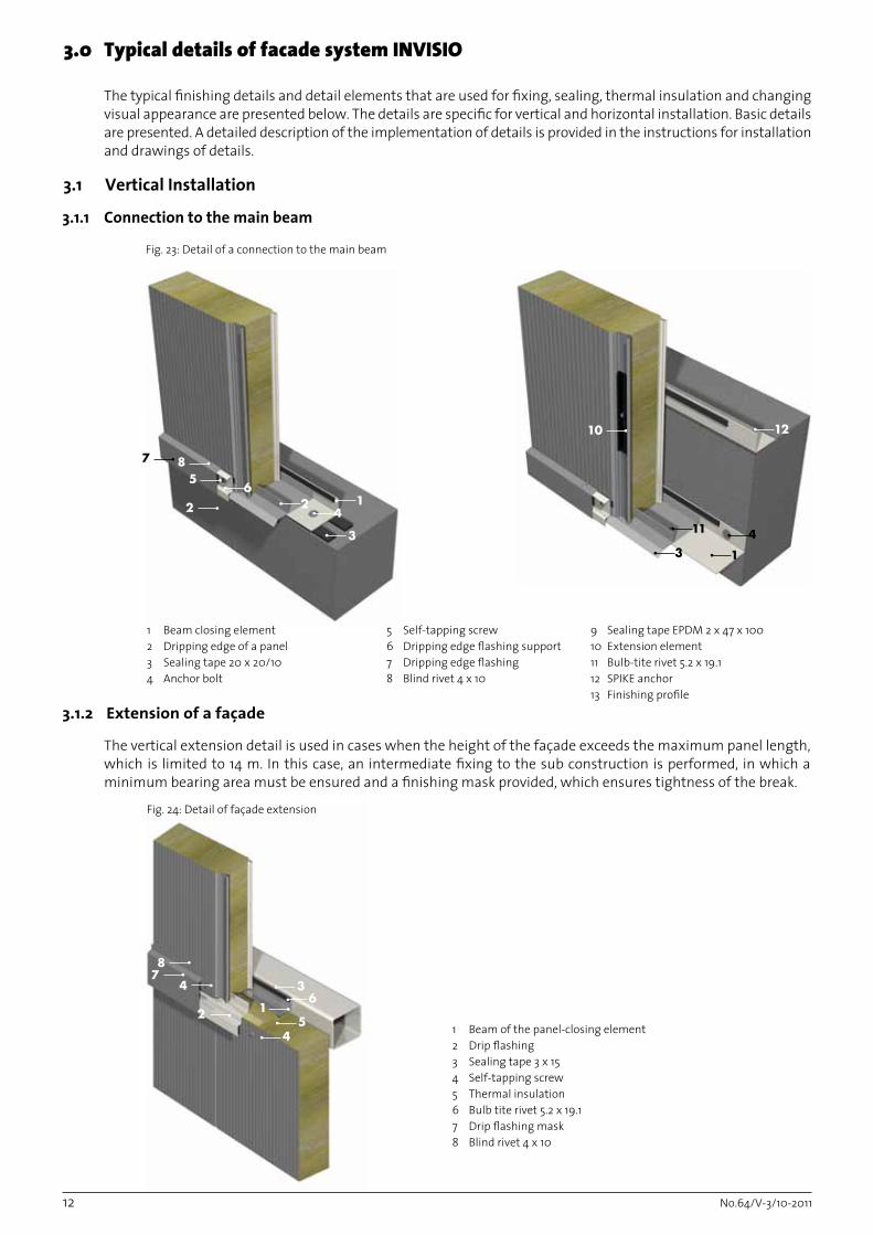
1 Beam closing element2 Dripping edge of a panel3 Sealing tape 20 x 20/104 Anchor bolt
3.0 TypicaldetailsoffacadesystemINVISIO
The typical finishing details and detail elements that are used for fixing, sealing, thermal insulation and changing visual appearance are presented below. The details are specific for vertical and horizontal installation. Basic details are presented. A detailed description of the implementation of details is provided in the instructions for installation and drawings of details.
The vertical extension detail is used in cases when the height of the façade exceeds the maximum panel length, which is limited to 14 m. In this case, an intermediate fixing to the sub construction is performed, in which a minimum bearing area must be ensured and a finishing mask provided, which ensures tightness of the break.
Fig. 23: Detail of a connection to the main beam
1 Beam of the panel-closing element2 Drip flashing3 Sealing tape 3 x 15 4 Self-tapping screw 5 Thermal insulation6 Bulb tite rivet 5.2 x 19.1 7 Drip flashing mask 8 Blind rivet 4 x 10
622
3
4
5
1
7 8
7
2
4
1
3
8
6
5
4
5 Self-tapping screw6 Dripping edge flashing support7 Dripping edge flashing8 Blind rivet 4 x 10
9 Sealing tape EPDM 2 x 47 x 10010 Extension element11 Bulb-tite rivet 5.2 x 19.112 SPIKE anchor 13 Finishing profile
Fig. 24: Detail of façade extension

No.64/V-3/10-2011 13
4
51
3
3
1
3
2
Figure 25: Detail of fixing to the top end support
Figure 26: Detail of fixing to the top end support with attics
3.1.3 Top End Support
3.1.4 Top End Support with attics
1 Self tapping screw2 Blind rivet 4 x 10³ Sealing tape 3 x 154 Attics cap5 Parapet cap carrier
6 Extension element7 Self-tapping screw8 Sealing tape EPDM 6 x 309 Thermal insulation
1 Self tapping screw2 Thermal insulation3 Sealing tape 3 x 154 Attics cap5 Parapet cap carrier
75
2
3
74
6
1
1
39
5
8
8
No.64/V-3/10-201114
1
3
4
1
5 5
2
4
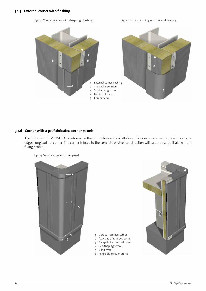
1 External corner flashing2 Thermal insulation 3 Self-tapping screw 4 Blind rivet 4 x 10 5 Corner beam
3.1.5 External corner with flashing
Fig. 27: Corner finishing with sharp edge flashing
3.1.6 Corner with a prefabricated corner panels
The Trimoterm FTV INVISIO panels enable the production and installation of a rounded corner (Fig. 29) or a sharp-edged longitudinal corner. The corner is fixed to the concrete or steel construction with a purpose-built aluminium fixing profile.
Fig. 29: Vertical rounded corner panel
1 Vertical rounded corner2 Attic cap of rounded corner 3 Parapet of a rounded corner4 Self-tapping screw5 Blind rivet6 HF102 aluminium profile
Fig. 28: Corner finishing with rounded flashing
2
35
1
6
4

No.64/V-3/10-2011 15
3.2.1 Connection to the main beam
Fig. 30: Detail of attachment to the base beam
Fig. 31: Detail of horizontal facade installation with panel mask at edge support
3.2.2 Panel Extension with a Mask
5
21
3
7
4
8
1
2 36
71 Panel support2 U profile 3 Anchor screw4 Sealing tape 3 x 155 L profile6 Blind rivet 4 x 10⁷ SPIKE anchor8 Bulb tite rivet
3
6
9
8
57
1
4
3.2 Horizontal installation
Classic extension is performed by fixing through the panels at both ends with at least two screws or in accordance with the static conversion. The joints are sealed with sealing tape and a mask, which is screwed to the exterior sheet metal of the panel (Fig. 31). The channel of the exterior joint is sealed with sealing putty and PE gasket.
1 Panel mask at edge support3 Sealing tape4 Thermal insulation5 Self-tapping screw6 Blind rivet 4 x 10⁷ Butyl tape on Alu foil 75 x 1.58 PE gasket9 Sealing putty
No.64/V-3/10-201116
2
16, 7
5
4
3
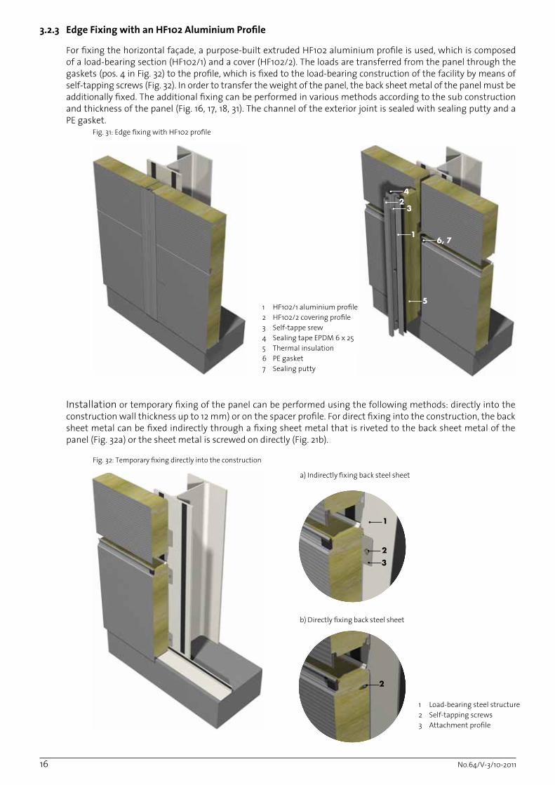
For fixing the horizontal façade, a purpose-built extruded HF102 aluminium profile is used, which is composed of a load-bearing section (HF102/1) and a cover (HF102/2). The loads are transferred from the panel through the gaskets (pos. 4 in Fig. 32) to the profile, which is fixed to the load-bearing construction of the facility by means of self-tapping screws (Fig. 32). In order to transfer the weight of the panel, the back sheet metal of the panel must be additionally fixed. The additional fixing can be performed in various methods according to the sub construction and thickness of the panel (Fig. 16, 17, 18, 31). The channel of the exterior joint is sealed with sealing putty and a PE gasket.
3.2.3 Edge Fixing with an HF102 Aluminium Profile
Fig. 31: Edge fixing with HF102 profile
1 HF102/1 aluminium profile2 HF102/2 covering profile3 Self-tappe srew4 Sealing tape EPDM 6 x 255 Thermal insulation 6 PE gasket7 Sealing putty
Fig. 32: Temporary fixing directly into the construction
1 Load-bearing steel structure2 Self-tapping screws3 Attachment profile
Installation or temporary fixing of the panel can be performed using the following methods: directly into the construction wall thickness up to 12 mm) or on the spacer profile. For direct fixing into the construction, the back sheet metal can be fixed indirectly through a fixing sheet metal that is riveted to the back sheet metal of the panel (Fig. 32a) or the sheet metal is screwed on directly (Fig. 21b).
a) Indirectly fixing back steel sheet
b) Directly fixing back steel sheet
1
23
2

No.64/V-3/10-2011 17
Indirectly fixing back steel sheet into spacer
Fig. 34: Indirectly fixing back steel sheet into spacer
1 Load-bearing steel structure2 Self-tapping screws3 Attachment profile4 Welded tube 40 x 40
In the case of Installation fixing in thick constructions, a spacer profile with the dimensions of 40 x 40 x2 or 40 x 20 x2, depending on the thickness of the panel appropriate for fixing is welded to the basic construction (Fig. 34). In this case, the back sheet metal is fixed directly through the Z-profile (Fig. 35), which is riveted to the interior sheet metal of the panel.
The shape of the Z-profile depends on the thickness of the panel or spacer profile (Fig. 35a, 35b, 35c).
Figure 35: Installation attachment
a) FTV 100 - FTV 240 HOP Z 40/40/40/2
b) FTV 60 - FTV 80 HOP Z 40/30/40/2
c) fastening without spacers profile (b < 12mm)
1 Panel Trimoterm FTV INVISIO2 Profile HOP Z40x_x23 Blind rivet 4 x 10
4
1
23
2
3
12
1
32
3
1

No.64/V-3/10-201118
4 2
8
3.2.4 Attics
1 Attics cap 2 Attics trim3 Finishing profile4 Self taping screw 6,3x25 Blind rivet 4 x 10⁶ Sealing tape EPDM 3x20
Attics in a horizontal layout panels is needed to be attached additional on middle support. The sub construction must be which is a mid-term fixing panel (Fig. 36). The closure is carried out by a combination of final borders, which look aesthetic complete facades.
3.2.5 Corner finish with corner lining
1 Angle of the panel - external2 Thermal insulation3 Self-tapping screw4 Blind rivet 4 x 10⁵ Corner support6 Corner beam
Fig. 37: Detail of corner finish with corner lining
Fig. 36: Detail attics
1
3
4
56
63
1
24
5

No.64/V-3/10-2011 19
3.2.6 Corner finish
Fig. 38: Detail of a sharp edge corner
Fig. 39: Detail of a round edge corner
1
2
3
1
2
3
1 Vertical corner2 Alu profile HF1023 Thermal insulation
1 Vertical corner2 Alu profile HF1023 Thermal insulation

No.64/V-3/10-201120
Fig. 41: Installation of window in to Al profile frame
Fig. 40: Performance of window dripping edges and flashing
The openings for installation of windows, doors and penetrations to the INVISIO façade system are finished with a classic mask (Fig. 40) or with a prefabricated aluminium profile with integrated thermal separation (Fig. 41).
1 Alu profile with thermal bridge2 Window3 Supporting structure4 Thermal insulation5 Flashing6 Sealing material7 Screw material
1 Window2 Bottom dripping edge3 Top dripping edge4 Flashing support5 Dripping edge flashing6 Sealing material7 Screw material
3.3 Window and other openings
3
24
1
5
42
3
3
4
1
2
5
3
5
No.64/V-3/10-2011 21
3.4 Curved Façade system INVISIO
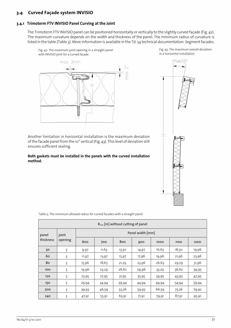
Rmin [m] without cutting of panel
panel thickness
joint opening
Panel width [mm]
600 700 800 900 1000 1100 1200
50 3 9,97 11,63 13,30 14,97 16,63 18,30 19,96
60 3 11,97 13,97 15,97 17,96 19,96 21,96 23,96
80 3 15,96 18,63 21,29 23,96 26,63 29,29 31,96
100 3 19,96 23,29 26,62 29,96 33,29 36,62 39,95
120 3 23,95 27,95 31,95 35,95 39,95 43,95 47,95
150 3 29,94 34,94 39,94 44,94 49,94 54,94 59,94
200 3 39,93 46,59 53,26 59,93 66,59 73,26 79,92
240 3 47,91 55,91 63,91 71,91 79,91 87,91 95,91
Fig. 42: The maximum joint opening in a straight panel with INVISIO joint for a curved façade
3.4.1 Trimoterm FTV INVISIO Panel Curving at the Joint
The Trimoterm FTV INVISIO panel can be positioned horizontally or vertically to the slightly curved façade (Fig. 42). The maximum curvature depends on the width and thickness of the panel. The minimum radius of curvature is listed in the table (Table 3). More information is available in the Td. 54 technical documentation: Segment facades.
Table 5: The minimum allowed radius for curved facades with a straight panel
Fig. 43: The maximum overall deviation in a horizontal installation
Another limitation in horizontal installation is the maximum deviation of the facade panel from the 10° vertical (Fig. 43). This level of deviation still ensures sufficient sealing.
Both gaskets must be installed in the panels with the curved installation method.

No.64/V-3/10-201122
Table 6: The minimum radius of a longitudinally curved panel
The Trimoterm FTV INVISIO segment panels can be prefabricated segment curved panels for positioning in a semi-circular form. The panels can be curved only around their longitudinal axis or parallel to the profile of the panel in +R or -R, as shown in the Figures (Fig. 44, Fig. 45). The length of the segment panel can be up to 14 m.
The marking of the Trimoterm FTV INVISIO segment panel is RV+ (Fig. 42) for convex and RV- (Fig. 43) for concave longitudinally curved panel.
Panel thickness Minimal radius [m]
60 1.5 m
80 1.9 m
100 2.4 m
120 2.9 m
150 3.5 m
200 4.8 m
Outside shape Aesthetic suitability
G *
X ***
m **
s **
v *
v1) ***
* Worse** Middle good*** Well
Table 7: Suitability of the profile of a longitudinally curved panel
3.4.2 Trimoterm FTV INVISIO Segment Panels
Fig. 44: Convex segment façade
Fig. 45: Concave segment façade

No.64/V-3/10-2011 23
4.0 Recommendationsforinstallation
NOTE:- If façade panels are stored for a long period of time, the foil should be removed within three months, at the latest.- If the façade panels are to be stored in the open, they should be protected against the sun; otherwise the complete removal of foil is no longer possible. - During assembly, the foil must be removed from all joints of the façade panel.
A protective foil for the protection of varnished surfaces against any possible damage caused during transport, handling, and assembly, is applied to INVISIO façade panels on both sides. Immediately before placement of the INVISIO façade panels to the assembly location it is necessary to:1. Completely remove the protective foil on the element’s internal side 2. Partially remove the protective foil on the element’s front side, that is on fixing locations, both longitudinal joints, under edges, etc. (Fig. 46 ).
4.1.1 Removing Protective Foil
NOTE:- Marking and scratching with nails or similar sharp objects that can damage the protective paint layer is strictly prohibited.- Use of any disc grinding machines and welding devices destroys the anti-corrosion protection.- Small metal particles that appear as a result of cutting and drilling MUST be immediately removed from the surfaces of panels by completion of the day’s work at the latest (metal particles exposed to moisture cause corrosion).
Invisio façade panel are made in accordance with project requirements and their cutting is generally not required! In case cutting is needed, only the use of sheet metal shears and saws that do not overheat the panel is allowed (Fig. 47). Use of a circular saw is recommended.
4.1.2 Elements Cutting
4.1 Preparing Element Prior to Installation
Fig 46: Removal of the protective foil
Fig. 47: Elements cutting is allowed sheet metal shears and saws
Restricted use
Recommended use

No.64/V-3/10-201124
4.2 Base requirements and tolerances for Trimoterm FTV INVISIO
The base onto which the panel can be attached is a concrete wall, skeletal concrete structure, steel structure or brick wall. Trimoterm FTV INVISIO panels can be attached directly to steel if substructure accuracy is sufficient and the substructure is less than 12 mm thick.
Before installation, check the measurements of the (sub) structure to which panels Trimoterm FTV INVISIO is attached. The structure must be within a +/- mm tolerance of the two extreme edges of the panel by length (Fig. 48).
The steel structure to which the panels are attached must adhere to ENV 1090-1 or internal Trimo requirements. This means that the construction can deviate from ideal project lines by no more than +/- 5 mm.
Fig. 48: Structure tolerances based on distances between two fields
The most important thing when designing and beginning the installation is, in addition to the above mentioned, deviation of the base beam. The base beam must be aligned and can deviate by a maximum of 5 mm at a distance of a single multi-field panel (Fig. 49). Otherwise, the panel will not be horizontal, which will cause deformation of the bottom joint. The load bearing profile of the base beam must be levelled using a spirit level.
Fig. 49: Tolerances of the concrete base beam
Detailed tolerance information is available in Trimo Technical Document No. 41 - Tolerances when installing in steel and concrete buildings.
No.64/V-3/10-2011 25
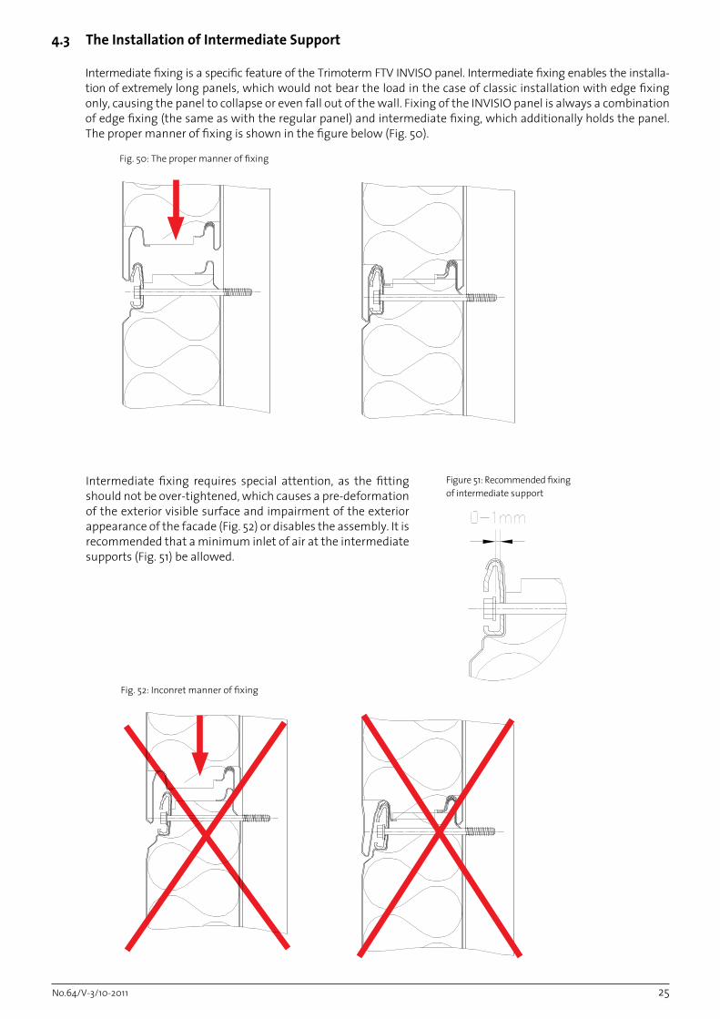
Fig. 50: The proper manner of fixing
Figure 51: Recommended fixing of intermediate support
4.3 The Installation of Intermediate Support
Intermediate fixing is a specific feature of the Trimoterm FTV INVISO panel. Intermediate fixing enables the installa-tion of extremely long panels, which would not bear the load in the case of classic installation with edge fixing only, causing the panel to collapse or even fall out of the wall. Fixing of the INVISIO panel is always a combination of edge fixing (the same as with the regular panel) and intermediate fixing, which additionally holds the panel. The proper manner of fixing is shown in the figure below (Fig. 50).
Fig. 52: Inconret manner of fixing
Intermediate fixing requires special attention, as the fitting should not be over-tightened, which causes a pre-deformation of the exterior visible surface and impairment of the exterior appearance of the facade (Fig. 52) or disables the assembly. It is recommended that a minimum inlet of air at the intermediate supports (Fig. 51) be allowed.

No.64/V-3/10-201126
The installation begins in the edge axis of the individual façade. Prior to the commencement of the installation of panels, it is necessary to check the geometric correctness of the sub construction, which is a prerequisite for a quality execution. Any possible geometric irregularities must be corrected by a suitable cutting of initial and end panels. The panels are leaned against the base frame, which partially bears the vertical loads.
For lifting and positioning the panel to the installation spots in the event of vertical or horizontal façade, the use of vacuum grips is recommended (Fig. 53, Fig. 54). Prior to lifting, the protective foil must be removed from the spots where the panel is sucked by the vacuum grip. A special grippers is also designed for vertical in horizontal installation (Fig. 55, 56).
The dimensions of the grip and pins must be determined aesthetically according to the thickness and weight of the panels.
Fig. 53: Vertical lifting with mechanical gripper Fig. 54: Vertical lifting with vacuum gripper
For lifting the panels with a thickness of 60, 80 and 100 mm, grips with pins φ 12 mm are used, and for panels with a thickness of more than 100 mm, gripper with pins φ 16 mm are used (Table 8). Bores for pins are made on spots that are later covered with masks.
INVISIO Typ of gripper
1 50 PVF - 50
2 60 PVF - 60
3 80 PVF - 80
4 100 PVF - 100
5 120 PVF - 120
6 133 PVF - 133
7 150 PVF - 150
8 172 PVF - 172
9 200 PVF - 200
10 240 PVF - 240
Table 8: Dimension of mechanical gripper
4.4 Manipulation and lifting panels
4.4.1 Vertical Installation

No.64/V-3/10-2011 27
Fig. 56: Horizontal lifting with vacuum gripper
Panel thickness Typ of gripper Max. panel Length
1 50 PHL - 50 (left, right) 12 m
2 60 PHL - 60 (left, right) 12 m
3 80 PHL - 80 (left, right) 12 m
4 100 PHL - 100 (left, right) 10 m
5 120 PHL - 120 (left, right) 10 m
6 133 PHL - 133 (left, right) 8 m
7 150 PHL - 150 (left, right) 8 m
Table 9: Dimension of mechanical gripper
Fig. 55: Horizontal lifting with mechanical gripper
4.4.2 Horizontal Installation
For lifting panel INVISIO can be used mechanical gripper (Figure 55). One pair of grippers is designed for lifting panel with a maximum weight of 300 kg. Type of gripper is determined by the thickness of the panel (Table 9). Instructions for using gripper is described in document TD 65.
No.64/V-3/10-201128
5.0 Packing,TransportandStoring
The guarantee and warranty conditions are listed in the warranty statement.
6.0MaintenanceofBuildings
6.1 Annual Service Inspection of Façade
The service inspection of the entire building and façade should be performed at least once per year. The purpose of the annual service inspection is detection and repairing of eventual deficiencies and thus prolonging the façade’s life-span. The annual service inspection includes:- Cleaning of all dirt and, if necessary, washing of the façade.- Eventual damage to the façade must be repaired immediately when noticed. The damaged spots are mechanically cleaned with fine abrasive cleaner (Scotch breit M600), dusted and digressed (cleansing alcohol, isopropyl alcohol). Then a layer of foundation paint is applied to the surface (air-dried coating based on epoxy binders and Zn pigments) and after that the final protection (air-dried coating based on polyurethane or acrylic binders).
6.2 General Recommendations
- Use of the aggressive substances for cleaning façades is not allowed since they may cause damage to the anti-corrosion protection.- Use of disc grinding machines (disc-cutting machines) near the panel is strictly forbidden, to prevent hot particles from damaging the varnish of panels.- In the case of any additional questions regarding building maintenance or eventual necessity of damage repairs, consult the Trimo Service Department.
7.0 Warranty
Information about packaging,transport and storage can be found in document no. 9 Packaging, Transport and Storage.

Publ
ishe
d by
: TRI
MO
d.d
., EN
, 11/
2011