fabcon guide specification - fabcon precast · 10.2 guide specification for...
TRANSCRIPT
Latest revision date: 12/20/12
10.2 GUIDE SPECIFICATION FOR
ARCHITECTURAL/STRUCTURAL PRECAST CONCRETE
Guideline Specifications
1. General
1.01 Description
A. Work included:
1. The specifications establish general criteria for materials, production,
erection and evaluation of precast concrete as required for subsequent
related sections of these specifications. The work to be performed shall
include all labor, material, equipment, related services, and supervision
required for the manufacture and erection of the architectural precast
concrete units shown on the contract drawings and schedules.
B. Related work specified elsewhere:
1. Concrete reinforcement: : Section _________________.
2. Cast-in-place reinforcement: Section_______________.
3. Precast, prestressed concrete: Section______________.
4. Structural steel framing: Section__________________.
5. Water repellent coatings: Section_________________.
6. Insulation: Section_____________________________.
7.Flashing and sheet metal: Section_________________.
8. Sealants and caulking: Section___________________.
9. Painting: Section______________________________.
10. Glass and glazing: Section______________________.
11. Glazing accessories: Section____________________.
C. Work installed but furnished by others.:
1. Counter flashing receivers or reglets: Section_______.
1.01.A Local standard practice may indicate that responsibility for
erection may not be included.
1.01.B.1 Architectural /Structural precast concrete reinforcing steel
requirements are different from cast-in-place reinforcement and should
be specified in this section
1.01.B.2 For placement of anchorage devices in cast-in-place concrete for precast concrete panels.
1.01.B.3 For precast floor and roof slabs, beams, columns and other structural elements. Some items, such as prestressed wall panels on industrial buildings, could be included in either specification, depending on the desired finish and tolerance expectation.
1.01.B.4 For steel supporting structure, attachment of anchorage
devices on steel for precast concrete panels, and sometimes loose
anchors/connectors.
1.01.B.5 For exposed face of panels. Delete when specified in this
section.
1.01.B.6 For insulation that is job-applied to precast concrete panels.
Insulation cast in precast concrete panels during manufacture should be
specified in this section.
1.01.B.7 For counter flashing inserts and receivers, unless included in
this section.
1.01.B.8 For panel joint caulking and sealing.
1.01.B.9 For field touch-up painting. Delete when specified in this
section.
1.01.B.10 For glazing of precast concrete panels in plant. Delete when
specified in this section.
1.01.B.11 For reglets used with structural glazing gaskets. Delete when
specified in this section.
1.01.C Delete when furnished by precast concrete manufacturer. Add
additional items as may be required for the particular project.
Notes to Specifiers
This Guide Specification is intended to be used as a foundation for the development of an office master specification or in the preparation of specifications for a particular project. In each
case, this Guide Specification must be modified to fit the conditions of use. Individual attention should be given to the deletion of inapplicable provisions and all essential items related to a
particular project should be included. Also, fitting requirements should be added where blank spaces have been provided. The Guide Specifications are on the left. Notes to Specifiers are
on the right.
Latest revision date: 12/20/12
Guideline Specifications 2. Inserts or attachments for:________ Section________.
D. Testing agency provided by owner or special inspection.
1.02 Quality Assurance
A. Manufacturer qualifications:
The precast concrete manufacturing plant shall be certified by the
Precast/Prestressed Concrete Institute Plant Certification Program, the
National Precast Concrete Association plant certification program, or other qualified
third party certification prior to start of fabrication of this project. Precast
concrete manufacturer must have produced product similar to what is being
specified for a minimum of five years. Manufacturer shall be certified at the time of
bidding. Certification shall be in the following product groups and categories:
___________ .
{OR}
Acceptable manufacturers:
1. ______________________________________
2. ______________________________________
B. Erector qualifications:
Regularly engaged for at least________ years in erection of architectural
precast concrete units similar to those required on this project.
C. Welder qualifications:
In accordance with AWS D1.1
D. Testing:
In general compliance with testing provisions in MNL-116 and MNL-117,
Manual for Quality Control for Plants and Production of Architectural
Precast Concrete Products.
PCI MNL-116, Manual for Quality Control for Plants and Production of
Precast and Prestressed Concrete Products, and
PCI MNL-116 and MNL-117, and
“Fabcon Design Guidelines for Precast Concrete Wall Panels”, current
version.
E. Testing agency:
1. Not less than ______ years experience in performing concrete tests of
type specified in this section.
2. Capable of performing testing in accordance with ASTM E 329.
3. Inspected by Cement and Concrete Reference Laboratory of the
National Institute of Standards and Technology.
F. Requirements of regulatory agencies:
Manufacture and installation of architectural/structural precast concrete
to meet requirements of______________________________________.
*ASTM Specifications—as referred to in Part 2, Products.
*AWS D1.1—Structural Welding Code—Steel
*ACI 318—Building Code Requirements for Reinforced Concrete
1.01.C.2 May include inserts/attachments for window or door frames,
window washing equipment, etc.
1.01.D Delete when testing agency is provided by precast concrete
manufacturer or general contractor. Coordinate with appropriate
section of Division 1, General Conditions.
1.02.A Groups and categories: (A1), (AT), (G). See Sect. 9.5 for
definitions. It is recommended that the architect approve individual
precast concrete manufacturers who meet the Quality Assurance
Specification at least ten days prior to the bid date, or identify approved
manufacturers in the specification. It is not appropriate to specify
structural products with architectural finishes in this section
1.02.B Usually 2 to 5 years.
1.02.C Certified within the past year. Delete when welding is not
required.
1.02.E Delete when provided by owner.
1.02.E.1 Usually 2 to 5 years.
1.02.F Local building code or other governing code relating to precast
concrete. For projects in Canada, standards from the Canadian
Standards Association should be listed in addition to or in place of the
U.S. standards.
Notes to Specifiers
Latest revision date: 12/20/12
Guideline Specifications G. Allowable tolerances:
H. 1. Manufacture and install wall panels so that each panel after erection
complies with the dimensional tolerances listed in MNL 116 OR MNL-
117 depending on product type expected.
I. Job mockup:
1. After standard samples are accepted for color and texture, submit full
-scale unit meeting design requirements as required.
2. Mockup to be standard of quality for architectural precast concrete
work, when accepted by architect/engineer.
3. Incorporate mockup into work in a location reviewed by architect/
engineer after keeping mockup in plant ______ for checking purpose.
I. Source quality control:
1. Quality control and inspection procedures to comply with applicable
sections of MNL-116/117.
2. Water absorption test on unit shall be conducted in accordance with
MNL-116/117.
1.03 Submittals
A. Samples:
1. Submit samples representative of finished exposed face showing
typical range of color and texture prior to commencement of production.
2. Sample size: Approximately 12 in. x 12 in. and of appropriate
thickness, representative of the proposed finished product.
B. Shop Drawings:
1. Erection drawings:
A. Member piece marks and completely dimensioned size
and shape each member.
B. Plans and/or elevations locating and defining all products
furnished by manufacturer.
C. Sections and details showing connections, cast-in items
and their relation to the structure.
D. Relationship to adjacent material.
E. Joints and openings between members.
F. Description of all loose, cast-in and field hardware.
1.02.G Dimensional tolerances apply to both manufacturing and after
manufacturing. The tolerances listed in PCI MNL-116 & MNL-117 are
also listed in Chapter 8 of the PCI Handbook. Most manufacturers can
meet closer tolerances, if required, but closer tolerances normally
increase costs. The normal tolerances of the support system should also
be recognized.
1.02.H.1 Full-scale samples or inspection of the first production unit may
be requested, especially when a new design concept or new
manufacturing process or other unusual circumstance indicates that
proper evaluation cannot otherwise be made. It is difficult to assess
appearance from small samples. Mockups are rarely required for
structural prestressed concrete.
1.02.H.2 Use to determine range of acceptability with respect to color
and texture variations, surface defects and overall appearance. Mockup
should also serve as testing areas for remedial work. It should also be
stated in the contract documents who the accepting authority will be.
1.02.H.3 Delete when mockup is not to be included in work. State how
long unit should be kept. Mockup is normally incorporated in the
building, at least for production units.
1.1.03.A Number of samples and submittal procedures should be
specified in Division 1. All approved samples should be initialed by the
architect. pre-bid samples should be submitted a minimum of 10 days
prior to bid date.
1.03.A1 If the back face of a precast concrete unit is to be exposed,
samples of the workmanship, color, and texture of the backing should
be shown as well as the facing.
1.03.B State the number of copies required for approval. Current
practice usually calls for three prints of shop drawings to be submitted
for approval. Submittal with architect/engineer to conform with allotted
shop drawing approval time shown on the precast concrete supplier’s
order acknowledgment. When erection drawings contain all
information sufficient for design approval, production drawings, except
for shape drawings, need not be submitted for approval, except in
special cases. However, record copies are frequently requested
Guidelines requested. for the preparation of drawings are given in the
PCI Drafting Handbook—Precast and Prestressed Concrete, Second
Edition, MNL-119-90.
1.03.B.1.D Details, dimensional tolerances and related information of
other trades affecting precast concrete work should be furnished to
precast concrete manufacturer.
Notes to Specifiers
Latest revision date: 12/20/12
Guideline Specifications G. Location, dimensional tolerances, and details of anchorage
devices that are embedded in or attached to structure or
other construction.
H. Erection sequences, when required to satisfy stability, and
handling requirements.
I. Reaction or loads to be identified in details as required.
2. Production drawings:
A. Member shapes (elevations and sections) and dimensions.
B. Sections and details to indicate quantities and position of
reinforcing steel, anchors, inserts, etc.
C. Handling devices.
D. Finishes.
E. Joint and connection details.
F. Methods for storage and transportation.
C. Design calculations:
Submit, on request, structural design calculations performed by an
engineer, registered in the state where the project is located,
experienced in the design of architectural/structural precast concrete.
D. Design modifications:
1. Submit design modifications necessary to meet performance
requirements and field coordination.
2. Variations in details or materials shall not adversely affect the
appearance, durability or strength of units.
3. Maintain general design concept without altering size of members,
profiles and alignment.
E. Test reports:
Submit, on request, reports on materials, compressive strength tests on
concrete and other tests on units.
1.04 Product delivery, storage and handling
A. Delivery and handling:
1. Deliver all architectural precast concrete units to project site in such
quantities and at such times to ensure continuity of erection.
2. Handle and transport units in a position consistent with their shape
and design in order to avoid stresses which would cause cracking or
damage.
3. Lift or support units only at the points shown on the shop drawings.
4. Support units during shipment w/shimming/dunnage material.
5. Do not place units directly on ground.
B. Storage at jobsite:
1. Store and protect units to prevent contact with soil, staining, and
physical damage.
2. Store units, unless otherwise specified, using adequate
supports located in same positions as when transported.
3. Store units on firm, level, and smooth surfaces.
4. Place stored units so that identification marks are discernible, and so
that product can be inspected.
1.03.B.1.G Drawings normally prepared by precast concrete
manufacturer and provided to general contractor for work by other
trades.
1.03.B.1.h If the sequence of erection is critical to the structural stability
of the structure, or for access to connections at certain locations, it
should be noted on the contract plans and specified.
1.03.D. 1-3 Modification should be agreed upon by all parties. Some
modifications may be necessary because of limitations from
manufacturing or structural complications.
1.03.E The number and/or frequency of each type of test should be
clearly stated in the specifications by listing the required testing or by
reference to applicable standards, such as PCI MNL-116/117. Schedule
of required tests, number of copies of test reports, and how distributed
are included in Testing Laboratory Services, Section ______ .
1.04.A Erector should coordinate arrival of precast concrete units and
provide for possible storage and for erection in a safe manner within the
agreed schedule and with due consideration for other trades. Handling
procedures, including type and location of fastenings, should normally
be left to the precaster. Erector can be manufacturer also.
1.04.B The ideal sequence of precast concrete erection is the
unloading of units directly to their proper location on the structure
without storing on the jobsite. If on-site storage is an absolute necessity
to enable the erector to operate at the speed required to meet the
established schedule leaving the precast concrete units on the trailer
eliminates extra handling or possible damage caused by improper on-
site storage techniques.
Notes to Specifiers
Latest revision date: 12/20/12
Guideline Specifications
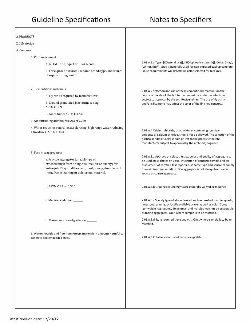
2. PRODUCTS
2.01Materials
A. Concrete:
1. Portland cement:
A. ASTM C 150, type I or III or blend.
B. For exposed surfaces use same brand, type, and source
of supply throughout.
2. Cementitious materials:
A. Fly ash as required by manufacturer
B. Ground granulated blast furnace slag:
ASTM C 989
C. Silica fume: ASTM C 1240.
3. Air entraining admixtures: ASTM C260
4. Water reducing, retarding, accelerating, high range water reducing
admixtures: ASTM C 494
5. Face mix aggregates:
a. Provide aggregates for each type of
exposed finish from a single source (pit or quarry) for
entire job. They shall be clean, hard, strong, durable, and
inert, free of staining or deleterious material.
b. ASTM C 33 or C 330.
c. Material and color: ______.
d. Maximum size and gradation: ______.
6. Water: Potable and free from foreign materials in amounts harmful to
concrete and embedded steel.
2.01.A.1.a Type: [I(General use)], [III(High early strength)]. Color: (gray),
(white), (buff). Gray is generally used for non-exposed backup concrete.
Finish requirements will determine color selected for face mix.
2.01.A.2 Selection and use of these cementitious materials in the
concrete mix should be left to the precast concrete manufacturer
subject to approval by the architect/engineer The use of fly ash a
and/or silica fume may affect the color of the finished concrete.
2.01.A.4 Calcium chloride, or admixtures containing significant
amounts of calcium chloride, should not be allowed. The selection of the
particular admixture(s) should be left to the precast concrete
manufacturer subject to approval by the architect/engineer.
2.01.A.5.a Approve or select the size, color and quality of aggregate to
be used. Base choice on visual inspection of concrete sample and on
assessment of certified test reports. Use same type and source of supply
to minimize color variation. Fine aggregate is not always from same
source as coarse aggregate.
2.01.A.5.b Grading requirements are generally waived or modified.
2.01.A.5.c Specify type of stone desired such as crushed marble, quartz,
limestone, granite, or locally available gravel as well as color. Some
lightweight Aggregates, limestones, and marbles may not be acceptable
as facing aggregates. Omit where sample is to be matched.
2.01.A.5.d State required sieve analysis. Omit where sample is to be m
matched.
2.01.A.6 Potable water is ordinarily acceptable.
Notes to Specifiers
Latest revision date: 12/20/12
Guideline Specifications
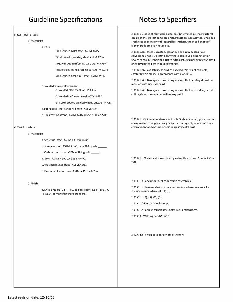
B. Reinforcing steel:
1. Materials:
a. Bars:
1) Deformed billet steel: ASTM A615
2)Deformed Low-Alloy steel: ASTM A706
3) Galvanized reinforcing bars: ASTM A767
4) Epoxy coated reinforcing bars ASTM A775
5) Deformed axel & rail steel: ASTM A966
b. Welded wire reinforcement:
(1)Welded plain steel: ASTM A185
(2)Welded deformed steel: ASTM A497
(3) Epoxy coated welded wire fabric: ASTM A884
c. Fabricated steel bar or rod mats: ASTM A184
d. Prestressing strand: ASTM A416, grade 250K or 270K.
C. Cast-in anchors:
1. Materials:
a. Structural steel: ASTM A36 minimum
b. Stainless steel: ASTM A 666, type 304, grade ______.
c. Carbon steel plate: ASTM A 283, grade ______.
d. Bolts: ASTM A 307 , A 325 or A490.
E. Welded headed studs: ASTM A 108.
F. Deformed bar anchors: ASTM A 496 or A 706.
2. Finish:
a. Shop primer: FS TT-P-86, oil base paint, type I, or SSPC-
Paint 14, or manufacturer’s standard.
2.01.B.1 Grades of reinforcing steel are determined by the structural
design of the precast concrete units. Panels are normally designed as c
crack-free sections or with controlled cracking, thus the benefit of
higher grade steel is not utilized.
2.01.B.1.a(1) State uncoated, galvanized or epoxy coated. Use
galvanizing or epoxy coating only where corrosive environment or
severe exposure conditions justify extra cost. Availability of galvanized
or epoxy coated bars should be verified.
2.01.B.1.a(2) Availability should be checked. When not available,
establish weld ability in accordance with AWS D1.4.
2.01.B.1.a(3) Damage to the coating as a result of bending should be
repaired with zinc-rich paint.
2.01.B.1.a(4) Damage to the coating as a result of mishandling or field
cutting should be repaired with epoxy paint.
2.01.B.1.b(3)Should be sheets, not rolls. State uncoated, galvanized or
epoxy coated. Use galvanizing or epoxy coating only where corrosive
environment or exposure conditions justify extra cost.
2.01.B.1.d Occasionally used in long and/or thin panels. Grades 250 or
270.
2.01.C.1.a For carbon steel connection assemblies.
2.01.C.1.b Stainless steel anchors for use only when resistance to
staining merits extra cost. (A),(B).
2.01.C.1.c (A), (B), (C), (D).
2.01.C.1.D For cast steel clamps.
2.01.C.1.e For low-carbon steel bolts, nuts and washers.
2.01.C.8 f Welding per AWDS1.1
2.01.C.2.a For exposed carbon steel anchors.
Notes to Specifiers
Latest revision date: 12/20/12
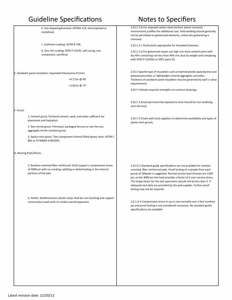
Guideline Specifications b. Hot-dipped galvanized: ASTMA 123, electroplated or
metallized.
c. Cadmium coating: ASTM B 766.
d. Zinc rich coating: DOD-P-21035, self curing, one
component, sacrificial.
E. Sandwich panel insulation: Expanded Polystyrene R (min)
=4.17/in @ 40°
=3.85/in @ 75°
F. Grout:
1. Cement grout: Portland cement, sand, and water sufficient for
placement and hydration.
2. Non-shrink grout: Premixed, packaged ferrous or non-ferrous
aggregate shrink-resistant grout.
3. Epoxy-resin grout: Two-component mineral-filled epoxy-resin: ASTM C
881 or FS MMM-A-001993.
G. Bearing Pads/Shims:
2. Random oriented fiber reinforced: Shall support a compressive stress
of 3000 psi with no cracking, splitting or delaminating in the internal
portions of the pad.
4. Plastic: Multimonomer plastic strips shall be non-leaching and support
construction loads with no visible overall expansion.
2.01.C.2.b For exposed carbon steel anchors where corrosive
environment justifies the additional cost. Field welding should generally
not be permitted on galvanized elements, unless the galvanizing is
removed.
2.01.C.2.c Particularly appropriate for threaded fasteners.
2.01.C.2.d For galvanized repair use high zinc-dust content paint with
dry film containing not less than 94% zinc dust by weight and complying
with DOD-P-21035A or SSPC paint 20.
2.01.E Specify type of insulation such as foamed plastic (polystyrene and
polyisocyanurate), or lightweight mineral aggregate concretes.
Thickness of sandwich panel insulation may be governed by wall U-value
requirements.
2.01.F Indicate required strengths on contract drawings.
2.01.F.2 Grout permanently exposed to view should be non-oxidizing
(non-ferrous).
2.01.F.3 Check with local suppliers to determine availability and types of
epoxy-resin grouts.
2.01.G.2 Standard guide specifications are not available for random
oriented, fiber reinforced pads. Proof testing of a sample from each
group of 200pads is suggested. Normal service load stresses are 1500
psi, so the 3000 psi test load provides a factor of 2 over service stress.
The shape factor for the test specimens should not be less than 2. If
adequate test data are provided by the pad supplier, further proof
testing may not be required.
2.0.1.G.4 Compression stress in use is not normally over a few hundred
psi and proof testing is not considered necessary. No standard guide
specifications are available
Notes to Specifiers
Latest revision date: 12/20/12
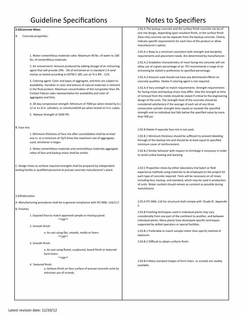
Guideline Specifications 2.02Concrete Mixes
A. Concrete properties:
1. Water-cementitious materials ratio: Maximum 40 lbs. of water to 100
lbs. of cementitious materials.
2. Air entrainment: Amount produced by adding dosage of air entraining
agent that will provide 19% - 3% of entrained air in standard 1:4 sand
mortar as tested according to ASTM C 185; our air % is 8% - 11%.
3. Coloring agent: Color and types of aggregate, and tints are subject to
availability. Variation in color and texture of natural materials is inherent
in the final product. Maximum concentration of tint not greater than 3%.
Contact Fabcon sales representative for availability and color of
aggregates and tints.
4. 28-day compressive strength: Minimum of 7000 psi when tested by 6 x
12 or 4 x 8 in. cylinders; or minimum6250 psi when tested on 4 in. cubes.
5. Release Strength of 3500 PSI.
B. Face mix:
1. Minimum thickness of face mix after consolidation shall be at least
one in. or a minimum of !Q/S times the maximum size of aggregates
used, whichever is larger.
2. Water-cementitious materials and cementitious materials-aggregate
ratios of face and backup mixes shall be similar.
C. Design mixes to achieve required strengths shall be prepared by independent
testing facility or qualified personnel at precast concrete manufacturer’s plant:
2.03Fabrication
A. Manufacturing procedures shall be in general compliance with PCI MNL-116/117.
B. Finishes:
1. Exposed face to match approved sample or mockup panel.
**OR**
2. Smooth finish:
a. As cast using flat, smooth, molds or liners.
**OR**
3. Smooth finish:
a. As cast using fluted, sculptured, board finish or textured
form liners.
**OR**
4. Textured finish:
a. Achieve finish on face surface of precast concrete units by
extrusion use of screeds.
2.02.A The backup concrete and the surface finish concrete can be of
one mix design, depending upon resultant finish, or the surface finish
(face mix) concrete can be separate from the backup concrete. Clearly
indicate specific requirements for each face of the product or allow
manufacturer’s option.
2.02.A.1 Keep to a minimum consistent with strength and durability
requirements and placement needs. Are determined by manufacturer.
2.02.A.2 Gradation characteristics of most facing mix concrete will not
allow use of a given percentage of air. PCI recommends a range of air
entraining be stated in preference to specified percentage.
2.02.A.3 Amount used should not have any detrimental effects on
concrete qualities. Delete if coloring agent is not required.
2.02.A.4 Vary strength to match requirements. Strength requirements
for facing mixes and backup mixes may differ. Also the strength at time
of removal from the molds should be stated if critical to the engineering
design of the units. The strength level of the concrete should be
considered satisfactory if the average of each set of any three
consecutive cylinder strength tests equals or exceeds the specified
strength and no individual test falls below the specified value by more
than 500 psi.
2.02.B Delete if separate face mix is not used.
2.02.B.1 Minimum thickness should be sufficient to prevent bleeding
through of the backup mix and should be at least equal to specified
minimum cover of reinforcement.
2.02.B.2 Similar behavior with respect to shrinkage is necessary in order
to avoid undue bowing and warping.
2.02.C Proportion mixes by either laboratory trial batch or field
experience methods using materials to be employed on the project for
each type of concrete required. Tests will be necessary on all mixes
including face, backup, and standard, which may be used in production
of units. Water content should remain as constant as possible during
manufacture.
2.03.A PCI MNL-116 for structural shall comply with ‘Grade B’, Appendix
C.
2.03.B Finishing techniques used in individual plants may vary
considerably from one part of the continent to another, and between
individual plants. Many plants have developed specific techniques
supported by skilled operators or special facilities.
2.03.B.1 Preferable to match sample rather than specify method of
exposure.
2.03.B.2 Difficult to obtain uniform finish.
2.03.B.4 Many standard shapes of form liners or screeds are readily
available.
Notes to Specifiers
Latest revision date: 12/20/12
Guideline Specifications
**OR**
5. Exposed aggregate finish:
a. Apply even coat of retardant to face of mold.
b. Remove units from molds after concrete hardens.
C. Expose coarse aggregate by washing and brushing or
lightly sandblasting away surface mortar.
d. Expose aggregate to produce a ______exposure.
**OR**
6. Sandblasted finish:
a. Sandblast away cementitious materials sand matrix to
produce a ______ exposure.
**OR**
7. Veneer faced finish:
a. Cast concrete over tile, brick, terra cotta or natural stone
placed in the bottom of the mold.
b. Connection of natural stone face material to concrete shall
be by mechanical means.
8. ______back surfaces of precast concrete units after striking surfaces
flush to form finish lines.
C. Cover:
1. Provide at least E/F in. cover for reinforcing steel.
2. Do not use metal chairs, with or without coating, in the finished face.
3. Provide embedded anchors, inserts, plates, angles and other cast-in
items with sufficient anchorage and embedment for design
requirements.
2.03.B.5.d (light) (medium) (deep). Finishes obtained vary from light
etch to heavy exposure, but must relate to the size of aggregates. Matrix
can be removed to a maximum depth of one-third the average diameter
of coarse aggregate but not more than one-half the diameter of smallest
sized coarse aggregate.
2.03.B.6.a (light) (medium) (deep). Exposure of aggregate by
sandblasting can vary from Q/AH in. or less to over E/K in.
Remove matrix to a maximum depth of one-third the average diameter
of coarse aggregate but not more than one-half the diameter of smallest
sized coarse aggregate. Depth of sandblasting should be adjusted to suit
the aggregate hardness and size.
2.03.B.7.a Full scale mockup units with natural stone in actual
production sizes, along with casting and curing of the units under
realistic production conditions are essential for each new or major
application or configuration of the natural stones.
2.03.B.7.b Provide a complete bond breaker between the natural stone
face material and the concrete. Ceramic tile, brick and terra cotta are
bonded to the concrete.
2.03.B.8 (Smooth float finish), (Smooth steel trowel), (Light broom),
(Stippled finish). Use for exposed back surfaces of units.
2.03.C.1 Increase cover requirements when units are exposed to
corrosive environment or severe exposure conditions. For exposed
aggregate surfaces, the E/F in. cover should be from bottom of
aggregate reveal to surface of steel.
2.03.C.2 If possible, reinforcing steel cages should be supported from
the back of the panel, because spacers of any kind are likely to mar the
finished surface of the panel. For smooth cast facing, stainless steel
chairs may be permitted. The wires should be soft stainless steel and
clippings should be completely removed from the mold.
Notes to Specifiers
Latest revision date: 12/20/12
Guideline Specifications
D. Molds:
1. Use rigid molds to maintain units within specified tolerances
conforming to the shape, lines and dimensions shown on the
approved shop drawings.
2. Construct molds to withstand vibration method selected.
E. Concreting:
1. Convey concrete from the mixer to place of final deposit by methods
which will prevent separation, segregation or loss of material.
2. Consolidate all concrete in the mold by high frequency vibration,
either internal or external or a combination of both, to eliminate
unintentional colds joints, honeycomb and to minimize entrapped air on
vertical surfaces.
F. Curing:
1. Precast concrete units shall be cured until the compressive strength is
high enough to ensure that stripping does not have an effect on the
performance or appearance of the final product.
G. Panel identification:
1. Mark each precast panel to correspond to identification mark on shop
drawings for panel location.
2. Mark each precast panel with date cast.
H. Acceptance:
Architectural precast units which do not meet the color and texture
range or the dimensional tolerances may be rejected at the option of
the architect, if they cannot be satisfactorily corrected.
2.03.D.2 Molds for architectural precast concrete should be built to
provide proper appearance, dimensional control and tightness. They
should be sufficiently rigid to withstand pressures developed by plastic
concrete, as well as the forces caused by consolidation. Unless
otherwise agreed in the contract documents, the molds are the
property of the precast concrete manufacturer.
2.03.E.2 The prime objective is to consolidate the concrete thoroughly,
producing a dense, uniform product with fine surfaces, free of
imperfections. Bonding between backup and face mix should be
ensured if backup concrete is cast before the face mix has attained its
initial set.
2.03.F A wide variation exists in acceptable curing methods, ranging
from no curing in some warm humid areas, to carefully controlled
moisture-pressure-temperature curing. Consult with local panel
manufacturers to avoid unrealistic curing requirements.
2.03.F.1 Stripping strength, which could be as low as 2000 psi, should be
set by the plant based on the characteristics of the product and plant
facilities. It is the responsibility of the precaster to verify and document
the fact that final design strength has been reached.
2.03.H It should be stated in the contract documents who the accepting
authority will be—contractor, architect, engineer of record, owner or
jobsite inspector.
Notes to Specifiers
Latest revision date: 12/20/12
Guideline Specifications 2.04Concrete Testing
A. Make one compression test at 28 days for each day’s production of each type of
concrete.
B. Specimens:
1. Provide two test specimens for each compression test.
2. Obtain concrete for specimens from actual production batch.
3. 6 in. x 12 in. or 4 in. x 8 in. concrete test cylinder, ASTM C 31.
**OR**
3. _________ sized concrete cube, ______________________.
4. Cure specimens using the same methods used for the precast
concrete units until the units are stripped, then moist cure specimens
until tested.
C. Keep quality control records available for the architect upon request for two
years after final acceptance.
3. EXECUTION
3.01 Inspection
A. Before erecting architectural precast concrete, the general contractor shall
verify that structure and anchorage inserts required to support panels are
within tolerances.
B. Determine field conditions by actual measurements.
3.02Erection
A. Clear, well-drained unloading areas and road access around and in the
structure (where appropriate) shall be provided and maintained by the
general contractor to a degree that the hauling and erection equipment for
the architectural precast concrete products are able to operate under their
own power.
B. General contractor shall erect adequate barricades, warning lights or signs to
safeguard traffic in the immediate area of hoisting and handling operations.
C. Set precast units level, plumb, square and true within the allowable
tolerances. General contractor shall be responsible for providing lines, center
and grades in sufficient detail to allow installation. General contractor shall
verify that bearing surfaces comply with specifications and, if not in
compliance, shall make necessary corrections prior to start of erection.
2.04.A This test should be only a part of an in-plant quality control
program.
2.04.B.3 Specify size. Cube specimens are usually 4 in. units, but 2 in. or
6 in. units are sometimes required. Larger specimens give more
accurate test results than smaller ones. Source: (molded individually),
(sawed from slab).
2.04.C These records should include mix designs, test reports,
inspection reports, member identification numbers along with date
cast, shipping records and erection reports.
3.0.1.B Any discrepancies between design dimensions and field
dimensions which could adversely affect installation in accordance with
the contract documents should be brought to the general contractor’s
attention. If such conditions exist, installation should not proceed until
they are corrected or until design requirements are modified. Beginning
of installation can mean acceptance of existing conditions.
3.02.A General contractor should coordinate delivery and erection of
precast concrete products with other jobsite operations.
3.02.C Controlled reference lines should be used because the
characteristics of precast concrete make a surface elevation difficult to
define. Where thickness is not of exact concern, lines used in erection
should be controlled from exposed exterior precast concrete surfaces.
Notes to Specifiers
Latest revision date: 12/20/12
Guideline Specifications D. Provide temporary supports and bracing as required to maintain position,
stability and alignment as units are being permanently connected.
E. Tolerances for location of precast units shall be in accordance with Chapter 8
of this Handbook.
F. Set non-load bearing units dry without mortar, attaining specified joint
dimension with steel or plastic spacing shims.
G. Fasten precast units in place by bolting or welding, or both, completing dry
packed joints, grouting sleeves and pockets, and/or placing cast-in-place
concrete joints as indicated on approved erection drawings.
H. Temporary lifting and handling devices cast into the precast concrete units
shall be completely removed or, if protectively treated, left in place unless
they interfere with the work of any other trade.
3.03 Repair
A. Repair exposed exterior surface to match color and texture of surrounding
concrete and to minimize shrinkage.
B. Adhere large patch to hardened concrete with bonding agent.
3.04Cleaning
A. After installation and joint treatment: ___________ shall clean soiled precast
concrete surfaces with detergent and water, using fiber brush and sponge, and
rinse thoroughly with clean water in accordance with precast concrete
manufacturer’s recommendation.
**OR**
B. After installation and joint treatment: Clean precast concrete panels with
____________.
C. Use acid solution only to clean particularly stubborn stains after more
conservative methods have been tried unsuccessfully.
D. Use extreme care to prevent damage to precast concrete surfaces and to
adjacent materials.
E. Rinse thoroughly with clean water immediately after using cleaner.
3.05 Protection
A. All work and materials of other trades shall be adequately protected by the
erector at all times.
B. A fire extinguisher, of an approved type and in operating condition, shall be
located within reach of all burning and welding operations at all times.
C. The erector shall be responsible for any chipping, spalling, cracking or other
damage to the units after delivery to the jobsite unless damage is caused in
site storage by others. After installation is completed, any further damage
shall be the responsibility of the general contractor
3.02.F Shims should be near the back of the unit to prevent their causing
a spall on face of unit when shim is loaded. The selection of the width
and depth of field-molded sealants, for the computed movement in a
joint, should be based on the maximum allowable strain in the sealant.
3.02.G The erector should protect units from damage caused by field
welding or cutting operations and provide non-combustible shields as
necessary during these operations. Structural welds should be made in
accordance with the erection drawings which should clearly specify
type, extent, sequence and location of welds. Adjustments or changes in
connections, which could involve additional stresses in the products or
connections, should not be permitted without approval by the architect/
engineer. Precast concrete units should be erected in the sequence
indicated on the approved erection drawings.
3.03.A Repair is normally accomplished prior to final cleaning and
caulking. It is recommended that the precaster execute all repairs or
approve the methods proposed for such repairs by other qualified
personnel. The precaster should be compensated for repairs of any
damage for which he is not responsible. Repairs should be acceptable
providing the structural adequacy of the product and the appearance
are not impaired. All repairs and remedial work should be documented
and kept in job record files.
3.03.B Bonding agent should not be used with small patches because of
the greater likelihood of discoloring the patch.
3.04.A State whether erector or precaster should do cleaning under the
responsibility of general contractor. Use cleaning materials or processes
which will not change the character of exposed concrete finishes.
3.04.B (acid-free commercial cleaners), (steam cleaning), (water
blasting), (sandblasting). Select cleaners with a non-chloride base. Use
sandblasting only for units with original sandblasted finish. Ensure that
materials of other trades are protected when cleaning panels.
3.05.C After erection of any portion of precast concrete work to proper
alignment and appearance, the general contractor should make
provisions to protect all precast concrete from damage and staining.
Notes to Specifiers