fabric defect detection using modified local binary patterns · on using these features is proposed...
TRANSCRIPT
Hindawi Publishing CorporationEURASIP Journal on Advances in Signal ProcessingVolume 2008, Article ID 783898, 12 pagesdoi:10.1155/2008/783898
Research ArticleFabric Defect Detection Using Modified Local Binary Patterns
F. Tajeripour,1 E. Kabir,1 and A. Sheikhi2
1 Department of Electrical Engineering, Tarbiat Modarres University, P.O. Box 14115-111, Tehran, Iran2 Department of Electrical and Electronics Engineering, Shiraz University, P.O. Box 71348-51154, Shiraz, Iran
Correspondence should be addressed to Farshad Tajeripour, [email protected]
Received 24 December 2006; Revised 22 May 2007; Accepted 4 October 2007
Recommended by Liang-Gee Chen
Local binary patterns (LBPs) are one of the features which have been used for texture classification. In this paper, a method basedon using these features is proposed for fabric defect detection. In the training stage, at first step, LBP operator is applied to animage of defect free fabric, pixel by pixel, and the reference feature vector is computed. Then this image is divided into windowsand LBP operator is applied to each of these windows. Based on comparison with the reference feature vector, a suitable thresholdfor defect free windows is found. In the detection stage, a test image is divided into windows and using the threshold, defectivewindows can be detected. The proposed method is multiresolution and gray scale invariant and can be used for defect detectionin patterned and unpatterned fabrics. Because of its simplicity, online implementation is possible as well.
Copyright © 2008 F. Tajeripour et al. This is an open access article distributed under the Creative Commons Attribution License,which permits unrestricted use, distribution, and reproduction in any medium, provided the original work is properly cited.
1. INTRODUCTION
Defect detection is an important problem in fabric qualitycontrol process. Cost reduction in production and inspectionprocess is also an important objective for textile manufac-turers. At present the quality inspection process is manuallyperformed by experts. Typical fabrics are 1–3 m wide and aredriven with speeds ranging from 20 to 200 m/min. Expertscannot detect more than 60% of the overall defects if the fab-ric moves faster than 30 m/min or wider than 2 m [1]. Likeother inspection processes, it has depended on workers’ ex-perience until now. The development of a flexible, efficient,reliable, and integrated real-time vision system for industrialapplication is an essential issue in quality control process fortextile manufacturers. In particular, if there is a defect, it re-duces the price of the fabric by 45%–65%. To increase theoverall quality, the homogeneity of fabric, and reliability, anautomated visual inspection system is needed for better pro-ductivity. Therefore, automation of visual inspection taskscan increase the efficiency of production lines and improvequality of the products as well. The previous works in thefield of automatic defect detection are mainly done on paper[2], steel roll [3], wood [4, 5], carpet [6], and textile [7–11].Most of the automatic fabric inspection systems are offlineand have detection speed up to 100 m/min. An importantpoint regarding these systems is that each of them can only
detect specific types of the defects. Therefore, detection speedand the range of the detectable defects are two main issues inthe field of automatic fabric inspection.
Many attempts have been made in the past three decadesto solve these problems. These attempts have been based onthree different approaches: statistical, spectral, and modelbased. In statistical approach, gray-level texture features ex-tracted from cooccurrence matrix [12], mean and standarddeviations of subblocks [13], autocorrelation of subimages[14], and Karhunen-Loeve (KL) transform [15] have beenused for the detection of fabric defects. Bodnarova et al.[16] made use of normalized cross-correlation functions fordetecting defects in fabrics. There exist many model-basedtechniques for fabric defect detection. For example, Cohen etal. [17] used a Markov random field (MRF) model for defectinspection of fabrics. Chen and Jain [18] used a structuralapproach to detect defects in textured images. Atalay [19] hasimplemented an MRF-based method on TMS320C40 paral-lel processing system for real-time defect inspection of fab-rics. Methods that use low-order MRF are not capable of de-tecting all kinds of the defects in fabric texture. In order todetect all kinds of the defects, the order of the model shouldbe increased. This yields an increase in computational com-plexity of the algorithm. There also exist many spectral ap-proaches for fabric defect detection. For example, Kumarand Pang [20] proposed a method for defect detection using
2 EURASIP Journal on Advances in Signal Processing
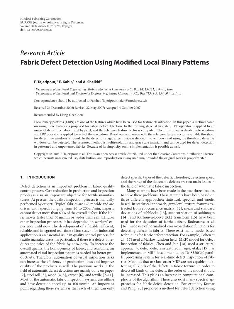
Unpatterned plain fabric Large repetitive unit(flower)
Patterned fabric
Repetitive pattern
Fabric
Dot patterned fabric
Figure 1: Classification of fabrics [23].
Gabor filters which needs a large amount of computations.They also developed a method for defect detection using onlyimaginary part of Gabor filters. Chan and Pang [21] offereda method for defect detection in textile fabrics using Fourieranalysis. Since Fourier bases are of infinite length, the con-tribution from each of the spectral components is difficultto quantify. Therefore, Fourier analysis is not suitable fordetecting local defects. Kumar and Pang [22] developed amethod for defect detection in textile fabrics using optimizedfilters.
It should be noted that most of the researches about fab-ric defect detection are made on unpatterned fabrics andonly a few works for defect detection in patterned fabricshave been reported. For example, Ngan et al. [23] used awavelet-based method for defect detection in patterned fab-rics. A patterned fabric is defined with repetitive patternedunits in its design. Under the class of patterned fabric, thereare many categories. Patterned fabrics that are used in thisresearch are Jacquard patterned fabrics. In these types of fab-rics a flower or a graphical logo may appear on the fabric.The repetitive unit can range from the simplest charter box,dots, to the most complicated multiple flower, animals, orother designed patterns. Besides there are a lot of subcate-gories under patterned fabric. Figure 1 illustrates a classifica-tion of fabrics [23].
The researches in this area can be divided into two dif-ferent categories. In the first category, all attempts are con-ducted to increase the range of the defects to be detected,while they need a large amount of computations. References[20–22] belong to this category. In the second one, increasingdetection speed is the aim, while a restricted range of defectscan be detected. References [12–19] belong to the second cat-egory.
In this paper, a simple and straightforward method fordetecting irregularities in fabric texture is proposed, whichcan detect a wide range of the defects. In this method, localbinary patterns (LBPs) are used. It should be noted that LBPis used for texture classification [24] but in this paper for thefirst time it is used for detecting textural defects in fabric. LBPis theoretically very simple, yet efficient approach for texture
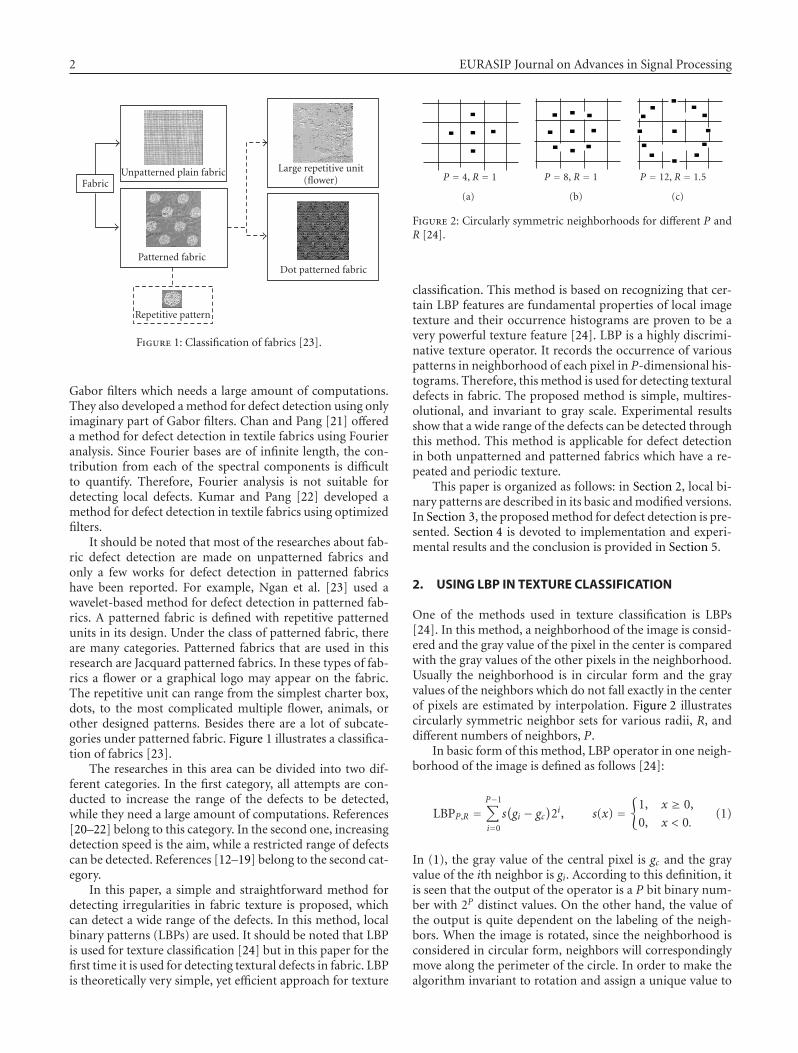
P = 4, R = 1
(a)
P = 8, R = 1
(b)
P = 12, R = 1.5
(c)
Figure 2: Circularly symmetric neighborhoods for different P andR [24].
classification. This method is based on recognizing that cer-tain LBP features are fundamental properties of local imagetexture and their occurrence histograms are proven to be avery powerful texture feature [24]. LBP is a highly discrimi-native texture operator. It records the occurrence of variouspatterns in neighborhood of each pixel in P-dimensional his-tograms. Therefore, this method is used for detecting texturaldefects in fabric. The proposed method is simple, multires-olutional, and invariant to gray scale. Experimental resultsshow that a wide range of the defects can be detected throughthis method. This method is applicable for defect detectionin both unpatterned and patterned fabrics which have a re-peated and periodic texture.
This paper is organized as follows: in Section 2, local bi-nary patterns are described in its basic and modified versions.In Section 3, the proposed method for defect detection is pre-sented. Section 4 is devoted to implementation and experi-mental results and the conclusion is provided in Section 5.
2. USING LBP IN TEXTURE CLASSIFICATION
One of the methods used in texture classification is LBPs[24]. In this method, a neighborhood of the image is consid-ered and the gray value of the pixel in the center is comparedwith the gray values of the other pixels in the neighborhood.Usually the neighborhood is in circular form and the grayvalues of the neighbors which do not fall exactly in the centerof pixels are estimated by interpolation. Figure 2 illustratescircularly symmetric neighbor sets for various radii, R, anddifferent numbers of neighbors, P.
In basic form of this method, LBP operator in one neigh-borhood of the image is defined as follows [24]:
LBPP,R =P−1∑
i=0
s(gi − gc
)2i, s(x) =
{1, x ≥ 0,
0, x < 0.(1)
In (1), the gray value of the central pixel is gc and the grayvalue of the ith neighbor is gi. According to this definition, itis seen that the output of the operator is a P bit binary num-ber with 2P distinct values. On the other hand, the value ofthe output is quite dependent on the labeling of the neigh-bors. When the image is rotated, since the neighborhood isconsidered in circular form, neighbors will correspondinglymove along the perimeter of the circle. In order to make thealgorithm invariant to rotation and assign a unique value to
F. Tajeripour et al. 3
each neighborhood, the output of LBP operator is rotatedand the minimum value is selected:
LBPriP,R = min
{ROR
(LBPP,R, i
) | i = 0, 1, . . . ,P − 1}. (2)
In (2), a P-bit number is rotated i times and the minimumvalue between resulting numbers for i between 0 to P − 1 isselected. In (2), ROR is the abbreviation of rotate right.
In modified version of LBP [24], at first a uniformitymeasure, U , is defined as the number of spatial transitionsbetween 1 s and 0 s in the pattern. Then patterns that haveuniformity measure less than UT are defined as uniform pat-terns. The modified LBP is defined as follows:
LBPriuTP,R =
⎧⎪⎪⎨⎪⎪⎩
P−1∑
p=0
s(gp − gc
)if U ≤ UT ,
P + 1 otherwise.
(3)
Equation (3) shows that modified LBP assigns labels from 0to P to uniform neighborhoods and label P + 1 to nonuni-form ones. After applying this operator to the image, theprobability of encountering a specific label can be approxi-mated by the ratio of the number of neighbors which havethat label to the number of all neighbors. Therefore, at theend of this process P+2 probabilities will be computed. Theseprobabilities can be used as powerful features for texture clas-sification. For classification task, the log-likelihood ratio isused. The sample under test belongs to class K if the com-puted probabilities minimize the following ratio:
L(S,K) =P+1∑
i=0
Si log(
SiMiK
). (4)
In (4), MiK is the probability of encountering label i in thepatterns of class K , and Si is the probability of encounteringlabel i found from the sample under test. According to (3),it is obvious that any monotonic change in gray values doesnot change the pattern and this method is invariant to grayscale changes.
3. THE PROPOSED ALGORITHM FORTEXTILE DEFECT DETECTION
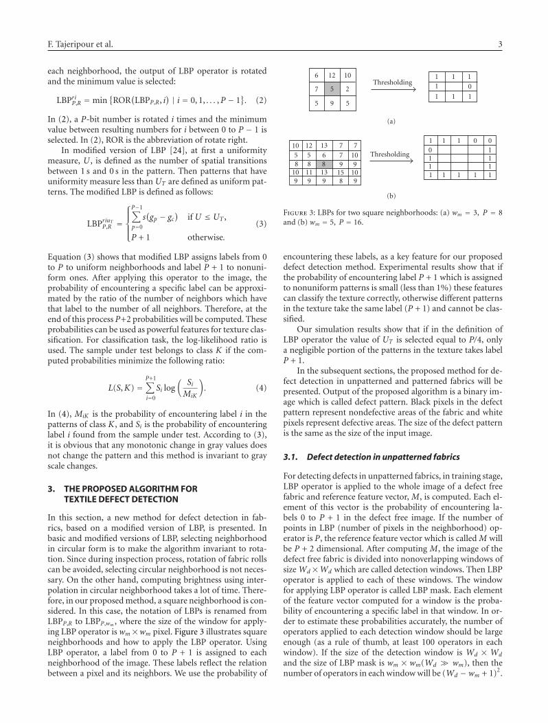
In this section, a new method for defect detection in fab-rics, based on a modified version of LBP, is presented. Inbasic and modified versions of LBP, selecting neighborhoodin circular form is to make the algorithm invariant to rota-tion. Since during inspection process, rotation of fabric rollscan be avoided, selecting circular neighborhood is not neces-sary. On the other hand, computing brightness using inter-polation in circular neighborhood takes a lot of time. There-fore, in our proposed method, a square neighborhood is con-sidered. In this case, the notation of LBPs is renamed fromLBPP,R to LBPP,wm , where the size of the window for apply-ing LBP operator is wm×wm pixel. Figure 3 illustrates squareneighborhoods and how to apply the LBP operator. UsingLBP operator, a label from 0 to P + 1 is assigned to eachneighborhood of the image. These labels reflect the relationbetween a pixel and its neighbors. We use the probability of
6 12 10
7 5 2
5 9 5
Thresholding1 1 11 0
1 1 1
(a)
10 12 13 7 7
5 5 6 7 108 8 8 9 9
10 11 13 15 109 9 9 8 9
Thresholding
1 1 1 0 00 11 11 11 1 1 1 1
(b)
Figure 3: LBPs for two square neighborhoods: (a) wm = 3, P = 8and (b) wm = 5, P = 16.
encountering these labels, as a key feature for our proposeddefect detection method. Experimental results show that ifthe probability of encountering label P + 1 which is assignedto nonuniform patterns is small (less than 1%) these featurescan classify the texture correctly, otherwise different patternsin the texture take the same label (P + 1) and cannot be clas-sified.
Our simulation results show that if in the definition ofLBP operator the value of UT is selected equal to P/4, onlya negligible portion of the patterns in the texture takes labelP + 1.
In the subsequent sections, the proposed method for de-fect detection in unpatterned and patterned fabrics will bepresented. Output of the proposed algorithm is a binary im-age which is called defect pattern. Black pixels in the defectpattern represent nondefective areas of the fabric and whitepixels represent defective areas. The size of the defect patternis the same as the size of the input image.
3.1. Defect detection in unpatterned fabrics
For detecting defects in unpatterned fabrics, in training stage,LBP operator is applied to the whole image of a defect freefabric and reference feature vector, M, is computed. Each el-ement of this vector is the probability of encountering la-bels 0 to P + 1 in the defect free image. If the number ofpoints in LBP (number of pixels in the neighborhood) op-erator is P, the reference feature vector which is called M willbe P + 2 dimensional. After computing M, the image of thedefect free fabric is divided into nonoverlapping windows ofsize Wd×Wd which are called detection windows. Then LBPoperator is applied to each of these windows. The windowfor applying LBP operator is called LBP mask. Each elementof the feature vector computed for a window is the proba-bility of encountering a specific label in that window. In or-der to estimate these probabilities accurately, the number ofoperators applied to each detection window should be largeenough (as a rule of thumb, at least 100 operators in eachwindow). If the size of the detection window is Wd × Wd
and the size of LBP mask is wm × wm(Wd � wm), then thenumber of operators in each window will be (Wd −wm + 1)2.
4 EURASIP Journal on Advances in Signal Processing
Therefore, if the minimum number of operators applied ineach window is 100, then Wd ≥ 9 + wm.
It should be noted that the features extracted by LBP op-erator can describe fabric texture correctly if the textures ap-peared in detection windows are similar to fabric texture.Therefore, the size of the detection window (Wd ×Wd) cre-ated on the image should be greater than the size of the repet-itive unit of fabric texture. However, in unpatterned fabricsthe only condition for window size is Wd ≥ 9 + wm. As thesize of the detection window increases, the capability of thealgorithm in detecting small defects and the resolution of thedefect pattern decrease. By applying LBP operator to each ofthese windows, vector Sk which is P + 2 dimensional is com-puted. The log-likelihood ratio for each of these windows willbe computed as follows:
Lk(Sk,M
) =P+1∑
i=0
Sik log(SikMi
), k = 1, 2, . . . ,N. (5)
In (5), N is the number of detection windows. Since the min-imization of log-likelihood ratio shows the similarity to aspecific class, the maximum value between these ratios willbe used as a threshold for defect-free windows as follows:
T = Max(Lk), k = 1, 2, . . . ,N. (6)
After computing reference feature vector M and thethreshold T , in the detection stage, the test image is dividedinto the detection windows and log-likelihood ratio is com-puted for each of these windows. If log-likelihood ratio ex-ceeds the threshold, the relevant window belongs to the de-fective areas of the fabric. In order to increase the detectioncapability of the algorithm, a large area of the detection win-dow should be occupied by the defect. Therefore, in the de-tection stage, image is divided into overlapping windows. Ac-cording to the simulation results, if the overlapping step ofthe detection windows is Wd/2, the proposed algorithm hasappropriate detection power. Increasing overlapping step willdecrease detection speed.
3.2. Defect detection in patterned fabrics
For detecting defects in patterned fabrics which have a peri-odic texture, in training stage, as it was mentioned in the pre-vious sections, at first LBP operator is applied to the wholeimage of a defect free sample then the image is divided intothe detection windows and LBP operator will be applied toeach of these windows. Since the fabrics are patterned if thesize of the window is less than the size of the repetitive unitin the fabric texture, then the texture in the detection win-dows will be different. So, the size of the detection windowshould be much greater than the repetitive unit of the fab-ric texture. Increasing the size of the detection window willincrease computational complexity and decreases the resolu-tion of the defect pattern. In order to solve this problem, thesize of the detection window will be chosen a little greaterthan the size of the repetitive unit in the fabric texture and inorder to take into account the interaction between all pixelswith their neighbors, the image is divided into overlapping
windows. In this case, if the size of LBP mask is wm × wm
pixel, overlapping step of wm − 1 between detection win-dows is sufficient to take into consideration the interactionbetween all pixels in different detection windows (interactionbetween pixels in the last column and the last row of a win-dow with pixels in the first column and the first row of theadjacent window). Using these types of windows, the thresh-old is computed as in (5) and (6). The remaining stages are asfor unpatterned fabrics. It should be noted that this methodis a multiresolution and the results of selecting different win-dows can be combined easily as follows:
LNK =N∑
n=1
LK(SnK ,Mn
), (7)
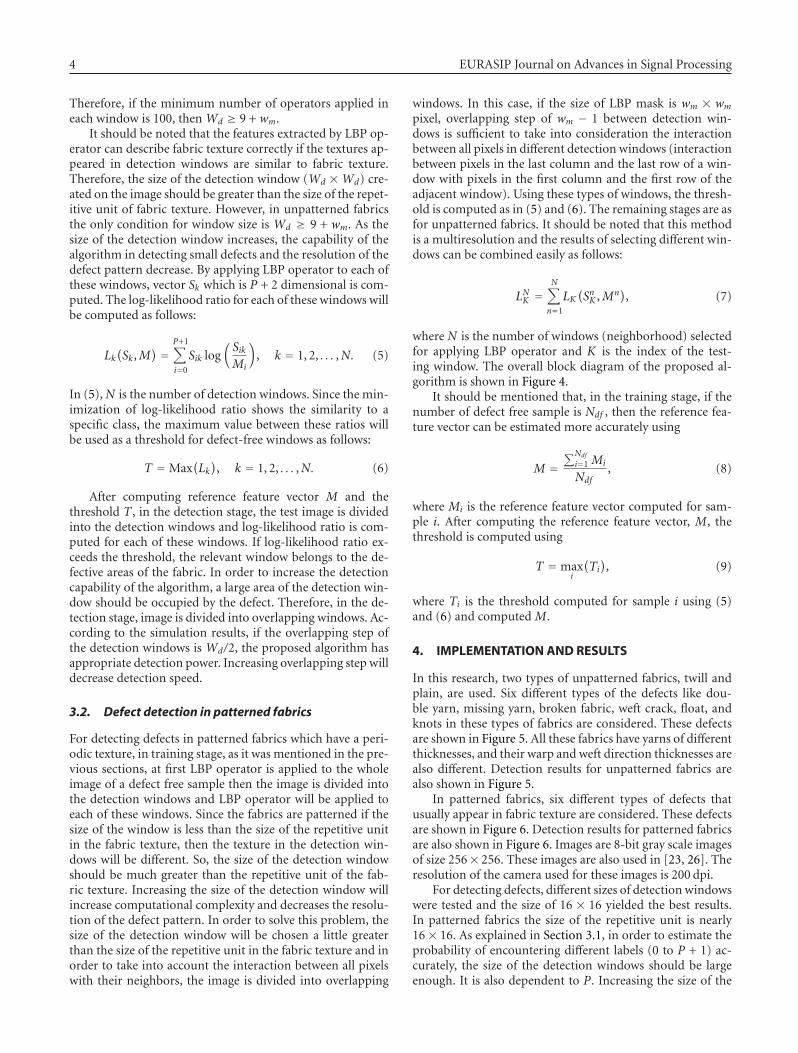
where N is the number of windows (neighborhood) selectedfor applying LBP operator and K is the index of the test-ing window. The overall block diagram of the proposed al-gorithm is shown in Figure 4.
It should be mentioned that, in the training stage, if thenumber of defect free sample is Ndf , then the reference fea-ture vector can be estimated more accurately using
M =∑Ndf
i=1 Mi
Ndf, (8)
where Mi is the reference feature vector computed for sam-ple i. After computing the reference feature vector, M, thethreshold is computed using
T = maxi
(Ti), (9)
where Ti is the threshold computed for sample i using (5)and (6) and computed M.
4. IMPLEMENTATION AND RESULTS
In this research, two types of unpatterned fabrics, twill andplain, are used. Six different types of the defects like dou-ble yarn, missing yarn, broken fabric, weft crack, float, andknots in these types of fabrics are considered. These defectsare shown in Figure 5. All these fabrics have yarns of differentthicknesses, and their warp and weft direction thicknesses arealso different. Detection results for unpatterned fabrics arealso shown in Figure 5.
In patterned fabrics, six different types of defects thatusually appear in fabric texture are considered. These defectsare shown in Figure 6. Detection results for patterned fabricsare also shown in Figure 6. Images are 8-bit gray scale imagesof size 256× 256. These images are also used in [23, 26]. Theresolution of the camera used for these images is 200 dpi.
For detecting defects, different sizes of detection windowswere tested and the size of 16 × 16 yielded the best results.In patterned fabrics the size of the repetitive unit is nearly16× 16. As explained in Section 3.1, in order to estimate theprobability of encountering different labels (0 to P + 1) ac-curately, the size of the detection windows should be largeenough. It is also dependent to P. Increasing the size of the

F. Tajeripour et al. 5
Applying LBPmask on image
Defect free image
Calculating referencefeature vector, M
Dividing imageinto detection
windows
Computing log likelihoodratio, L for each detection
window
Finding the
threshold, T
(a) Training stage
Test sampleDividing imageinto detection
windows
Computing log likelihoodratio, L for each detection
window using M
If L > T , label window asdefective else non defective
M T
(b) Testing stage
Figure 4: Overall block diagram of the proposed algorithm.
(a) (b) (c) (d) (e)
Figure 5: (a) Images of defective unpatterned fabrics from top to bottom: double yarn, missing yarn, broken fabric, weft crack, float, andknot. Detection results in the form of defect pattern using (b) LBP8,3, (c) LBP16,5, (d) LBP24,7, and (e) LBP8,3+16,5.
detection windows decreases the capability of the algorithmin detecting small size defects. Experimental results show thatif there are at least 100 operators in each detection window,the probability of encountering different labels can be esti-
mated accurately. Since the maximum size of LBP mask inthe proposed algorithm is 7× 7, the size of 16× 16 for detec-tion windows is sufficient for estimating these probabilitiesaccurately.
6 EURASIP Journal on Advances in Signal Processing
(a) (b) (c) (d) (e)
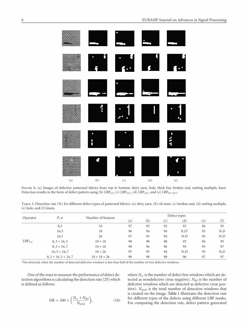
Figure 6: (a) Images of defective patterned fabrics from top to bottom: dirty yarn, hole, thick bar, broken end, netting multiple, knot.Detection results in the form of defect pattern using (b) LBP8,3, (c) LBP16,5, (d) LBP24,7, and (e) LBP8,3+16,5.
Table 1: Detection rate (%) for different defect types of patterned fabrics: (a) dirty yarn, (b) oil stain, (c) broken end, (d) netting multiple,(e) hole, and (f) knots.
Operator P,w Number of featuresDefect types
(a) (b) (c) (d) (e) (f)
LBPP,w
8,3 10 97 95 95 92 96 95
16,5 18 96 94 94 N.D1 95 N.D
24,7 26 97 95 94 N.D 95 N.D
8, 3 + 16, 5 10 + 18 98 98 98 95 96 95
8, 3 + 24, 7 10 + 26 98 96 96 94 95 97
16, 5 + 24, 7 18 + 26 97 95 94 N.D 95 N.D
8, 3 + 16, 5 + 24, 7 10 + 18 + 26 98 98 98 96 97 971Not detected, when the number of detected defective windows is less than half of the number of true defective windows.
One of the ways to measure the performance of defect de-tection algorithms is calculating the detection rate [25] whichis defined as follows:
DR = 100×(Ncc + Ndd
Ntotal
), (10)
where Ncc is the number of defect free windows which are de-tected as nondefective (true negative). Ndd is the number ofdefective windows which are detected as defective (true pos-itive). Ntotal is the total number of detection windows thatis created on the image. Table 1 illustrates the detection ratefor different types of the defects using different LBP masks.For computing the detection rate, defect pattern generated

F. Tajeripour et al. 7
Table 2: Detection rate (%) for different defect types of unpatterned fabrics: (a) Double Yarn, (b) Missing Yarn, (c) Broken Fabric, (d) WeftCrack, (e) Float, and (f) Knots.
Operator P,w Number of featuresDefect types
(a) (b) (c) (d) (e) (f)
LBPP,w
8,3 10 97 85 95 92 94 95
16,5 18 98 90 93 90 94 93
24,7 26 95 N.D 93 90 93 90
8, 3 + 16, 5 10 + 18 98 98 98 95 97 97
8, 3 + 24, 7 10 + 26 98 96 96 94 95 95
16, 5 + 24, 7 18 + 26 97 N.D 94 92 95 94
8, 3 + 16, 5 + 24, 7 10 + 18 + 26 99 98 98 96 97 97
(a) (b) (c) (d)
Figure 7: (a) Images of defective fabrics, (b) defect pattern generated by the method of [26], (c) defect pattern generated by proposedalgorithm (overlapping step 8 pixels), and (d) defect pattern generated by proposed algorithm (overlapping step 15 pixels).
by the algorithm is divided into 16× 16 windows and a win-dow that contains at least one white pixel is considered asdefective. Since images are of size 256 × 256, Ntotal is 256. Inour image dataset of patterned fabrics, there exist sixty im-ages of dot patterned Jacquard fabrics. Half of these imagesare defect free. Training stage is done using only five sam-ples of defect free images. In testing stage all of the defect freesamples are classified correctly. On the other hand, for each
type of the defects there exist five different images in our dataset. The detection rate listed in Table 1 is the average of thedetection rates for all of the defective images in the database.In Table 2 detection rates for different types of the defects inunpatterned fabrics are listed.
As shown in Figures 5 and 6, a 3 × 3 mask for apply-ing LBP operator, LBP8,3, detects almost all kinds of the de-fects, but the defect pattern found for patterned fabrics is not
8 EURASIP Journal on Advances in Signal Processing
Table 3: Detection rate (%) of proposed algorithm and algorithm of [26] tested on dot patterned fabrics: (a) dirty yarn, (b) hole, (c) oilstain, (d) knot, (e) broken end, and (f) netting multiple.
AlgorithmDefect type
Average detection rate(a) (b) (c) (d) (e) (f)
Reference [26] 96 97 94 95 95 94 95.1
Proposed1 98 95 97 94 97 93 95.8
Proposed2 98 96 98 94 98 95 96.51Overlapping step 8 pixels.
2Overlapping step 15 pixels.
continuous and exact in unpatterned fabrics. Therefore, thefeatures of 3×3 mask are combined with the features of 5×5and 7 × 7 masks using (7). On the other hand, using 5 × 5and 7× 7 (LBP16,5 and LBP24,7) masks for detection as illus-trated in Table 1 do not detect defects like netting multipleand knots. Table 1 shows that combination of features of 3×3and 5 × 5 masks (LBP8,3+16,5) has an appropriate detectionrate (more than 95%).
4.1. Performance comparison
In the subsequent subsections, the performance of the pro-posed algorithm is compared with the performance of simi-lar algorithms. For performance comparison two criteria areused:
(1) defect detection accuracy,(2) computational complexity and speed.
For comparing the detection accuracy of the algorithms,the defect patterns generated by different algorithms arecompared visually. The detection rate is also used to comparethe detection accuracy.
In order to compare the computational complexity, thenumber of operations required for processing a test sampleis considered.
4.1.1. Patterned fabrics
In order to make a comparison between the proposedmethod and the existing methods for defect detection in pat-terned fabrics, the results of the proposed method are com-pared with the results of methods in [26, 27]. These methodsare the two newest methods for detecting defects in patternedfabrics. In the training stage of the method of [26], a win-dow of a defect free sample is selected. The size of this win-dow should be greater than the size of the repeated part offabric texture. This window will be moved on a defect freesample image pixel by pixel. At each point, difference be-tween gray values of pixels in the window and gray valuesof pixels in the underlying window on the image is com-puted. The average of absolute value of differences is com-puted for each point. By defining a suitable threshold, de-fective points can be detected. Images of patterned fabricsin both methods are the same. Comparison of the resultsin Figure 7 reveals that in some specific types of the defectslike knot and hole, the method of [26] yields more accuratedefect pattern; and in some other types like dirty yarn, oil
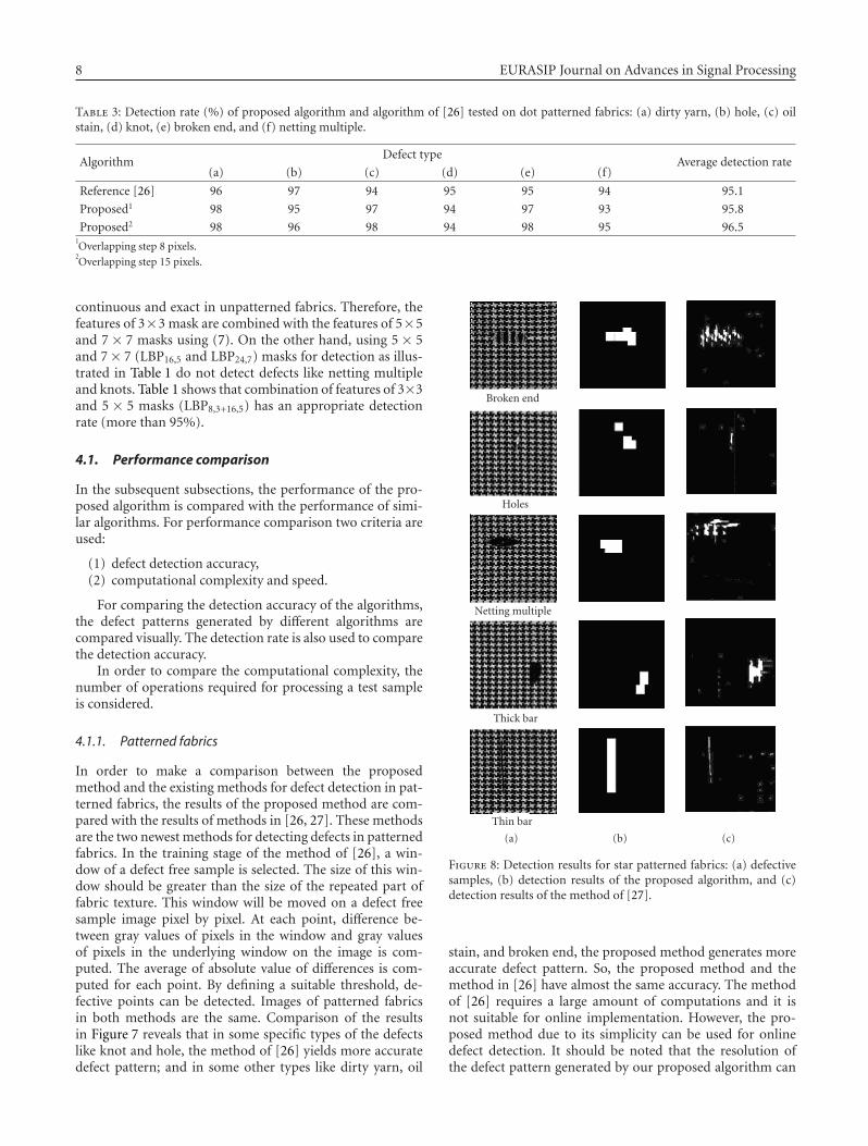
Broken end
Holes
Netting multiple
Thick bar
Thin bar
(a) (b) (c)
Figure 8: Detection results for star patterned fabrics: (a) defectivesamples, (b) detection results of the proposed algorithm, and (c)detection results of the method of [27].
stain, and broken end, the proposed method generates moreaccurate defect pattern. So, the proposed method and themethod in [26] have almost the same accuracy. The methodof [26] requires a large amount of computations and it isnot suitable for online implementation. However, the pro-posed method due to its simplicity can be used for onlinedefect detection. It should be noted that the resolution ofthe defect pattern generated by our proposed algorithm can
F. Tajeripour et al. 9
Table 4: Detection rate (%) of proposed algorithm and algorithm of [27] tested on star patterned fabrics: (a) thin bar (dirty yarn), (b) hole,(c) thick bar (oil stain), (d) broken end, and (e) netting multiple.
AlgorithmDefect type
Average detection rate(a) (b) (c) (d) (e)
Reference [27] 95 95 94 93 96 94.6
Proposed1 97 97 96 98 96 96.8
Proposed2 98 97 99 98 95 97.41Overlapping step 12 pixels.
2Overlapping step 24 pixels.
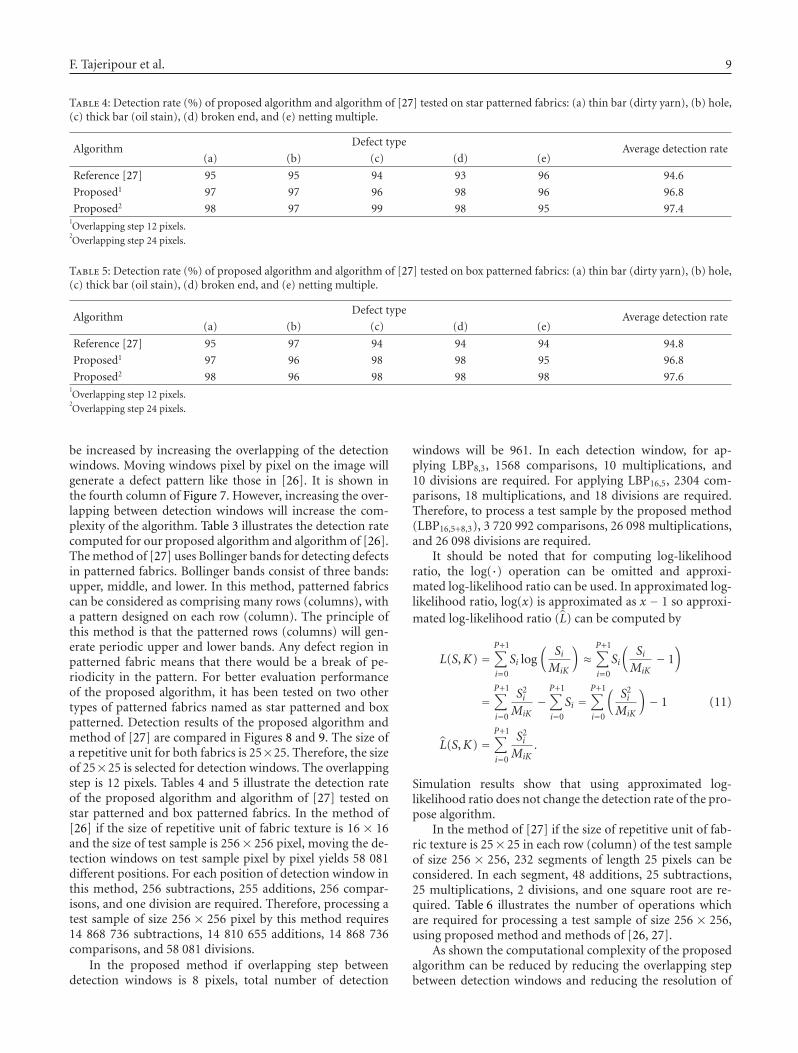
Table 5: Detection rate (%) of proposed algorithm and algorithm of [27] tested on box patterned fabrics: (a) thin bar (dirty yarn), (b) hole,(c) thick bar (oil stain), (d) broken end, and (e) netting multiple.
AlgorithmDefect type
Average detection rate(a) (b) (c) (d) (e)
Reference [27] 95 97 94 94 94 94.8
Proposed1 97 96 98 98 95 96.8
Proposed2 98 96 98 98 98 97.61Overlapping step 12 pixels.
2Overlapping step 24 pixels.
be increased by increasing the overlapping of the detectionwindows. Moving windows pixel by pixel on the image willgenerate a defect pattern like those in [26]. It is shown inthe fourth column of Figure 7. However, increasing the over-lapping between detection windows will increase the com-plexity of the algorithm. Table 3 illustrates the detection ratecomputed for our proposed algorithm and algorithm of [26].The method of [27] uses Bollinger bands for detecting defectsin patterned fabrics. Bollinger bands consist of three bands:upper, middle, and lower. In this method, patterned fabricscan be considered as comprising many rows (columns), witha pattern designed on each row (column). The principle ofthis method is that the patterned rows (columns) will gen-erate periodic upper and lower bands. Any defect region inpatterned fabric means that there would be a break of pe-riodicity in the pattern. For better evaluation performanceof the proposed algorithm, it has been tested on two othertypes of patterned fabrics named as star patterned and boxpatterned. Detection results of the proposed algorithm andmethod of [27] are compared in Figures 8 and 9. The size ofa repetitive unit for both fabrics is 25×25. Therefore, the sizeof 25×25 is selected for detection windows. The overlappingstep is 12 pixels. Tables 4 and 5 illustrate the detection rateof the proposed algorithm and algorithm of [27] tested onstar patterned and box patterned fabrics. In the method of[26] if the size of repetitive unit of fabric texture is 16 × 16and the size of test sample is 256× 256 pixel, moving the de-tection windows on test sample pixel by pixel yields 58 081different positions. For each position of detection window inthis method, 256 subtractions, 255 additions, 256 compar-isons, and one division are required. Therefore, processing atest sample of size 256 × 256 pixel by this method requires14 868 736 subtractions, 14 810 655 additions, 14 868 736comparisons, and 58 081 divisions.
In the proposed method if overlapping step betweendetection windows is 8 pixels, total number of detection
windows will be 961. In each detection window, for ap-plying LBP8,3, 1568 comparisons, 10 multiplications, and10 divisions are required. For applying LBP16,5, 2304 com-parisons, 18 multiplications, and 18 divisions are required.Therefore, to process a test sample by the proposed method(LBP16,5+8,3), 3 720 992 comparisons, 26 098 multiplications,and 26 098 divisions are required.
It should be noted that for computing log-likelihoodratio, the log(·) operation can be omitted and approxi-mated log-likelihood ratio can be used. In approximated log-likelihood ratio, log(x) is approximated as x − 1 so approxi-mated log-likelihood ratio (L) can be computed by
L(S,K) =P+1∑
i=0
Si log(
SiMiK
)≈
P+1∑
i=0
Si
(SiMiK
− 1)
=P+1∑
i=0
S2i
MiK−
P+1∑
i=0
Si =P+1∑
i=0
(S2i
MiK
)− 1
L(S,K) =P+1∑
i=0
S2i
MiK.
(11)
Simulation results show that using approximated log-likelihood ratio does not change the detection rate of the pro-pose algorithm.
In the method of [27] if the size of repetitive unit of fab-ric texture is 25× 25 in each row (column) of the test sampleof size 256 × 256, 232 segments of length 25 pixels can beconsidered. In each segment, 48 additions, 25 subtractions,25 multiplications, 2 divisions, and one square root are re-quired. Table 6 illustrates the number of operations whichare required for processing a test sample of size 256 × 256,using proposed method and methods of [26, 27].
As shown the computational complexity of the proposedalgorithm can be reduced by reducing the overlapping stepbetween detection windows and reducing the resolution of

10 EURASIP Journal on Advances in Signal Processing
Table 6: Number of different operations which are required to process a test sample using different algorithms.
Algorithm Size of repetitive unit of fabric texture Addition subtraction Multiplication comparison division Square root
Proposed1 16× 16 23064 0 26098 3720992 26098 0
Proposed2 25× 25 8424 0 9072 3657312 9072 0
[26] 16× 16 14810655 14868736 0 14868736 58081 0
[26] 25× 25 33586176 33640000 0 33640000 53824 0
[27] 16× 16 3701760 1974272 1974272 0 123392 123392
[27] 25× 25 5701632 2969600 2969600 0 118784 1187841Overlapping step of 8 pixels between detection windows.
2Overlapping step of 12 pixels between detection windows.
Broken end
Holes
Netting multiple
Thick bar
Thin bar
(a) (b) (c)
Figure 9: Detection results for box patterned fabrics: (a) defectivesamples, (b) detection results of the proposed algorithm, and (c)detection results of the method of [27].
the defect pattern, which cannot be done in similar algo-rithms.
4.1.2. Unpatterned fabrics
For evaluating performance of the algorithm in detecting de-fects of unpatterned fabrics, the detection results of the pro-
(a) (b) (c)
Figure 10: (a) Defective fabric images, (b) detection results usingour proposed algorithm, and (c) detection results using Gabor fil-ters.
posed algorithm are compared with those of the defect de-tection using Gabor filters [28]. Defect detection using Ga-bor filters is one of the most accurate methods [29]. In thismethod [28], an image of a defect free sample is passedthrough a bank of Gabor filters. Transfer function of eachfilter is obtained by changing scale and orientation of the Ga-bor functions. In the method selected for comparison, there
F. Tajeripour et al. 11
exist 16 filters in the filter bank, which are obtained by chang-ing the orientation and scale of Gabor functions to four ori-entations and four scales. Output of each filter is thresholdedand combined with the output of the other filters using animage fusion technique. So, for each filter in the filter bank, aset of suitable parameters are computed. Passing test samplethrough these filters will generate a defect pattern that detectsand localizes the irregularities in fabric texture. Figure 10 il-lustrates the detection results of the proposed algorithm andthe detection results using Gabor filters. Some of the imagesof unpatterned fabrics were scanned from album of standarddefects in textile industry [30] and the others were collectedfrom textile mills around TamilNadu state of India. Theseimages are gray-scale images with 8 bits long and with thesize of 256× 256. If we use a procedure for computing detec-tion rate like what was used for patterned fabrics, the aver-age detection rate for proposed algorithm will be 97.1% andfor Gabor filters will be 98%. The methods that have beenbased on Gabor filters use the idea of multichannel filteringwhich takes a lot of time. Therefore, these methods have alittle chance for online implementation.
5. CONCLUSION
In this paper, a new method for detecting textural defectsin fabrics based on modified local binary patterns has beenpresented. The proposed method has an acceptable detec-tion rate (more than 95%) in all kinds of the defects whichis more than that of human experts in both unpatterned andpatterned fabrics. Furthermore, detecting all kinds of the de-fects needs considering different windows which can be easilydone using the multiresolution property of this method.
This method is a useful tool for textile industries to in-spect, identify, and localize local defects in textile products.The proposed method is simple, gray-scale invariant, andmultiresolution. According to the performance comparisonand implementation results, it is evident that the proposedmethod can detect and localize defects in patterned fabrics,more accurately than similar algorithms. The computationalcomplexity of the proposed algorithm is less than similar al-gorithms. Therefore, it can be used in online defect detection.
In spite of low-resolution defect pattern, the defect pat-tern generated by the proposed method is suitable for a widerange of the defects. It should be mentioned that, practically,the detection rate and detection speed are of higher privilegethan the resolution of the defect pattern generated by the al-gorithm.
The proposed method is implemented on three typesof patterned fabrics: dot patterned, box patterned, star pat-terned and two types of unpatterned fabrics: twill and plain.Six different types of patterned fabric defects and six differenttypes of unpatterned fabrics are considered in this research.Implementation results show that the proposed method iscapable of detecting all kinds of the defects in both types ofthe fabrics. It should be noted that this method can be usedfor defect identification too. It can also be used for defect de-tection in products which have regular and periodic texturessuch as timber or plastic.
ACKNOWLEDGMENTS
The authors would like to thank Henry Y. T. Ngan and Indus-trial Automation Research Laboratory, Department of Elec-trical and Electronic Engineering, The University of HongKong, for providing the database of patterned fabrics. Theyalso would like to thank S. Arivazhagan for providing somesamples of unpatterned fabrics.
REFERENCES
[1] C.-S. Cho, B.-M. Chung, and M.-J. Park, “Development ofreal-time vision-based fabric inspection system,” IEEE Trans-actions on Industrial Electronics, vol. 52, no. 4, pp. 1073–1079,2005.
[2] J. W. Roberts, S. D. Rose, G. A. Jullian, et al., “PC based real-time defect imaging system for high speed web inspection,” inMachine Vision Applications in Industrial Inspection, vol. 1907of Proceedings of SPIE, pp. 164–176, San Jose, Calif, USA,February 1993.
[3] J. Laitinen, “Image quality in automated visual web inspec-tion,” in Machine Vision Applications in Industrial InspectionV, vol. 3029 of Proceedings of SPIE, pp. 78–89, San Jose, Calif,USA, February 1997.
[4] R. W. Conners, C. W. McMillin, K. Lin, and R. E. Vasquez-Espinosa, “Identifying and locating surface defects in wood:part of an automated lumber processing system,” IEEE Trans-actions on Pattern Analysis and Machine Intelligence, vol. 5,no. 6, pp. 573–583, 1983.
[5] E. Young, “Use of linescan cameras and a DSP processing sys-tem for high-speed wood inspection,” in Machine Vision Ap-plications, Architectures, and Systems Integration IV, vol. 2597of Proceedings of SPIE, pp. 259–264, Philadelphia, Pa, USA,October 1995.
[6] L. Siew, R. M. Hodgson, and E. J. Wood, “Texture measures forcarpet wear assessment,” IEEE Transactions on Pattern Analysisand Machine Intelligence, vol. 10, no. 1, pp. 92–105, 1988.
[7] S. H. Sheen, H. T. Chien, W. P. Lawrence, and A. C. Raptis,“Ultrasonic imaging system for in-process fabric defect detec-tion,” U.S. Patent no. 5665 907, September 1997.
[8] L. Dorrity and G. Vachtsevanos, “In-process fabric defect de-tection and identification,” in Proceedings of Mechatronics,Skovde, Sweden, September 1998.
[9] C.-H. Chan and G. K. H. Pang, “Fabric defect detection byFourier analysis,” IEEE Transactions on Industry Applications,vol. 36, no. 5, pp. 1267–1276, 2000.
[10] H. Sari-Sarraf and J. S. Goddard Jr., “Vision system for on-loom fabric inspection,” IEEE Transactions on Industry Appli-cations, vol. 35, no. 6, pp. 1252–1259, 1999.
[11] A. Kumar and G. Pang, “Fabric defect segmentation usingmultichannel blob detectors,” Optical Engineering, vol. 39,no. 12, pp. 3176–3190, 2000.
[12] I.-S. Tsai, C.-H. Lin, and J.-J. Lin, “Applying an artificial neu-ral network to pattern recognition in fabric defects,” TextileResearch Journal, vol. 65, no. 3, pp. 123–130, 1995.
[13] X. F. Zhang and R. R. Bresee, “Fabric defect detection andclassification using image analysis,” Textile Research Journal,vol. 65, no. 1, pp. 1–9, 1995.
[14] E. J. Wood, “Applying fourier and associated transforms topattern characterization in textiles,” Textile Research Journal,vol. 60, no. 4, pp. 212–220, 1990.
12 EURASIP Journal on Advances in Signal Processing
[15] M. Unser and F. Ade, “Feature extraction and decision proce-dure for automated inspection of textured materials,” PatternRecognition Letters, vol. 2, no. 2, pp. 181–191, 1984.
[16] A. Bodnarova, M. Bennamoun, and K. K. Kubik, “Defect de-tection in textile materials based on aspects of the HVS,” inProceedings of IEEE International Conference on Systems, Manand Cybernetics (SMC ’98), vol. 5, pp. 4423–4428, San Diego,Calif, USA, October 1998.
[17] F. S. Cohen, Z. Fan, and S. Attali, “Automated inspection oftextile fabrics using textural models,” IEEE Transactions onPattern Analysis and Machine Intelligence, vol. 13, no. 8, pp.803–808, 1991.
[18] J. Chen and A. K. Jain, “A structural approach to identify de-fects in textured images,” in Proceedings of IEEE InternationalConference on Systems, Man, and Cybernetics (SMC ’88), vol. 1,pp. 29–32, Beijing, China, August 1988.
[19] A. Atalay, “Automated defect inspection of textile fabrics usingmachine vision techniques,” M.S. thesis, Bogazici University,Istanbul, Turkey, 1995.
[20] A. Kumar and G. K. H. Pang, “Defect detection in texturedmaterials using Gabor filters,” IEEE Transactions on IndustryApplications, vol. 38, no. 2, pp. 425–440, 2002.
[21] C.-H. Chan and G. K. H. Pang, “Fabric defect detection byFourier analysis,” IEEE Transactions on Industry Applications,vol. 36, no. 5, pp. 1267–1276, 2000.
[22] A. Kumar and G. K. H. Pang, “Defect detection in texturedmaterials using optimized filters,” IEEE Transactions on Sys-tems, Man, and Cybernetics, Part B, vol. 32, no. 5, pp. 553–570,2002.
[23] H. Y. T. Ngan, G. K. H. Pang, S. P. Yung, and M. K. Ng,“Defect detection on patterned jacquard fabric,” in Proceed-ings of the 32nd Applied Imagery Pattern Recognition Work-shop (AIPR ’03), pp. 163–168, Washington, DC, USA, October2003.
[24] T. Ojala, M. Pietikainen, and T. Maenpaa, “Multiresolutiongray-scale and rotation invariant texture classification with lo-cal binary patterns,” IEEE Transactions on Pattern Analysis andMachine Intelligence, vol. 24, no. 7, pp. 971–987, 2002.
[25] A. Bodnarova, M. Bennamoun, and K. K. Kubik, “Suitabilityanalysis of techniques for flaw detection in textiles using tex-ture analysis,” Pattern Analysis and Applications, vol. 3, no. 3,pp. 254–266, 2000.
[26] H. Y. T. Ngan, G. K. H. Pang, S. P. Yung, and M. K. Ng,“Wavelet based methods on patterned fabric defect detection,”Pattern Recognition, vol. 38, no. 4, pp. 559–576, 2005.
[27] H. Y. T. Ngan and G. K. H. Pang, “Novel method for patternedfabric inspection using Bollinger bands,” Optical Engineering,vol. 45, no. 8, Article ID 087202, 15 pages, 2006.
[28] S. Arivazhagan, L. Ganesan, and S. Bama, “Fault segmentationin fabric images using Gabor wavelet transform,” Machine Vi-sion and Applications, vol. 16, no. 6, pp. 356–363, 2006.
[29] A. Latif-Amet, A. Ertuzun, and A. Ercil, “Efficient method fortexture defect detection: sub-band domain co-occurrence ma-trices,” Image and Vision Computing, vol. 18, no. 6-7, pp. 543–553, 2000.
[30] Graniteville Company, “Manual of Standard Fabric Defects inthe Textile Industry,” Graniteville, SC, USA, 1975.