name fabricatio… · 9.3. cut-outs 9.3.1. cut-outs – factory made 9.3.2. cut-outs ... essastone...
TRANSCRIPT

The undersigned acknowledges receipt of this manual
Customer Details
Company:
Address:
Telephone Number:
Name:
Signature:
Date: / /
Laminex
Name:
Signature:
Date: / /
Registration Number:
(as shown on the spine of the manual)
Please forward to:Laminex essastone Technical ManagerPO Box 407Doncaster VIC 3108
Issue: V5.00 – April 2016
essastone technical and fabrication manual receiptLaminex copy (please return to Laminex)
essastone® technical and fabrication manual receipt

Issue: V5.00 – April 2016
essastone technical and fabrication manual receiptcustomer copy
essastone® technical and fabrication manual receipt
The undersigned acknowledges receipt of this manual
Customer Details
Company:
Address:
Telephone Number:
Name:
Signature:
Date: / /
Laminex
Name:
Signature:
Date: / /
Registration Number:
(as shown on the spine of the manual)
Section/Date Section/Date
Updated:
1. introduction 1.1. purpose of the manual 1.2. the company behind essastone
2. safety guidelines 2.1. personal safety equipment 2.2. general safety protocols
3. applications 3.1. interior applications 3.2. exterior applications
4. product specifications 4.1. product composition
5. inspection identification/logistics 5.1. visual inspection 5.2. batch/lot identification 5.3. colour matching from different batches/lots 5.4. material handling and storage 5.5. material transport
6. design guidelines 6.1. cabinet requirements 6.2. benchtop support 6.2.1. full perimeter support 6.2.2. full substrate support 6.3. span and overhang support 6.3.1. spans 6.3.2. dishwashers 6.3.3. overhang support 6.4. internal corners 6.4.1. benchtops 6.4.2. cut-outs 6.5. joint location 6.5.1. “U”, “L” and angle-shaped fabrications 6.5.2. joint location for sink and appliance cut-outs 6.6. exposed edge profiles 6.7. expansion gap and dimensional tolerances 6.8. splashbacks – design considerations 6.9. splashbacks – installation 6.9.1. splashback installation requirements 6.9.2. splashback installation guidelines 6.9.3. powerpoint installation
7. preparation, templating and measurement 7.1. general guidelines 7.2. levelling 7.3. key considerations
8. adhesive method to substrate 8.1 substrate – benchtops
Issue: V5.00 – April 2016
contents
contents
Laminex. A division of Laminex Group Pty Limited ABN 98 004 093 092. essastone is marketed and distributed byLaminex. essastone is a registered Trademark of Laminex. ASW 979897 – 4/16
Issue: V5.00 – April 2016
contents
contents
9. fabrication 9.1. basic guidelines 9.2. cutting 9.3. cut-outs 9.3.1. cut-outs – factory made 9.3.2. cut-outs – on-site 9.4. internal corners 9.4.1. benchtops 9.4.2. cut-outs 9.5. edge profiles 9.5.1. laminations 9.5.2. waterfall ends 9.6. edge polishing 10. sinks, cook tops, and appliances 10.1. sinks 10.1.1. drop-in sinks 10.1.2. under-mount sinks 10.2. laundry tubs & taps 10.3. washing machine/dryer installation 10.4. external use barbeques 11. installation
12. repairs
13. care and maintenance
14. key considerations for your essastone project
15. warranty 14.1. typical responsibilities of the stone fabricator 14.2. 15-year limited warranty general terms and conditions
16. MSDS – material safety data sheets
1. introduction
intro
ductio
n
Issue: V5.00 – April 2016
introduction1.1. purpose of the manual
introduction 1
A key purpose of this manual is to guide fabricators of the essastone product in ensuring the finished article iscompliant with the 15 year limited essastone warranty.
Throughout this manual the symbol will appear against any specific instructions that are linked tocompliance or voiding the essastone warranty.
essastone quartz surfaces are manufactured by a group of the world’s leading manufacturers of engineeredstone, made from the finest natural quartz and silica, using the latest and most advanced manufacturingtechniques. essastone is a non-porous surface material that is stain and scratch resistant.
This manual has been developed to allow designers, fabricators and installers who work with essastone toachieve excellent performance standards and meet the expectations of the purchaser for both domesticand commercial applications.
There are many brands of engineered quartz surfaces on the market and each brand has its own individualproduct characteristics, so it is important to note that all fabrication techniques described in this manualare those recommended for use with essastone. Any variation from these guidelines may create unexpectedperformance problems and may void the limited warranty.
Users of this manual should adhere to all recommendations specified. All health and safety guidelines must beunderstood before commencing any work with essastone. Fabricators should also ensure that they are awareof and comply with all local, state and federal health and safety regulations.
essastone has been developed for a wide range of applications using a variety of design methods. Anymethod of design, fabrication or installation not detailed in this manual must be discussed with Laminex prior tofabrication. In this situation, approval must be sought in writing from Laminex or the limited warranty may be void.
To make this manual easy-to-use and navigate, information is provided in sections. Each section can be readindependently and some repetition will be evident. Each section provides comprehensive information ondifferent aspects of the design, measurement, fabrication and installation of essastone; however, this manualshould be viewed as a complete document.
While every precaution has been taken in the preparation of this document, Laminex assumes no responsibilityfor errors or omissions, or for damages resulting from the use of information contained in this document. In noevent shall Laminex be liable for any loss of profit or any other loss or damage caused or alleged to have beencaused directly or indirectly as a result of any person relying upon any information contained in this document.
The information contained in this manual is provided as a guide for the design, measurement, fabrication andinstallation of essastone. Except as required by law, no warranty, however expressed or implied, is given inrelation to the procedures outlined in this document.
Content in this manual is subject to change at any time without notice. Consult with your local essastonerepresentative for access to the latest technical updates.
This manual is not for general distribution. It has been developed for essastone fabricators and essastone installers.
Other essastone information available includes:• Product Sample folder• Product brochure • Material Safety Data Sheets (MSDS) - attached in this manual in section 15.
W

essastone is the most colour and design relevant brand of quartz surfaces on the market. essastone wasdeveloped in Australia for Australian preferences using the knowledge and colour leadership of Laminex,Australia’s leading marketer, distributor and manufacturer of decorative surfaces.
Laminex conducted extensive research into market trends and manufacturing technology before enteringthe engineered quartz surface market and continues to engage in wide consultation across the design andconstruction industry to ensure the essastone range remains market relevant. The result is a product thatreflects all the beauty of nature, without some of the complexities of natural stone. The latest advancementsin both the manufacturing process, produce a virtually maintenance-free surface.
As an industry leader, Laminex is well aware of the need to offer both the fabricator and customers clearguidelines for the design, fabrication, installation and ongoing care and maintenanceof essastone.
For more information, or to contact your local sales representative, please call 132 136 or visitwww.essastone.com.au
Issue: V5.00 – April 2016
1.2. the company behind essastone
introduction 1

2. safety guidelines
safe
ty guid
elin
es

essastone should be handled with care to ensure the safety of staff and others who may be in the vicinity ofthe work area. When handling essastone products, ensure all relevant safety procedures are followed andappropriate personal protective equipment, such as gloves, safety footwear, glasses, respiratory and hearingprotection is used. Always consider foreseeable hazards and adhere to all applicable regulations regardingoccupational health and safety.
When handling the product always consider its weight and dimensions. Always follow the recommendationsprovided by manufacturers of lifting equipment. If unsure, check with the equipment manufacturer beforecommencing work.
Engineered quartz products are safe and are not hazardous as shipped from the manufacturing plant.However, operations such as cutting, shaping or grinding will generate silica dust. Exposure to silica dust inquantities exceeding exposure standards can cause adverse health effects.
When working with essastone, the use of WET cutting, shaping and polishing is essential. It is also importantto ensure adequate cross-flow ventilation to minimise the exposure to airborne dust contaminants.Mechanical extraction units and dampeners may assist to maintain airborne concentrations within exposurestandards.
Note: Refer to the MSDS for the additional information on the correct storage, fabrication and handlingrequirements in section 15 of this manual.
2.1. personal safety equipment
All personnel involved in handling or fabricating essastone materials must be equipped with the adequatesafety equipment, including:
• steel capped rubber soled boots or shoes (AS/NZS 2210)• respiratory particle filter dust mask to approved (AS/NZS 1715 and 1716) when processing/fabricating• safety glasses (AS/NZS 1337) when processing/fabricating• ear plugs/ear muffs (AS/NZS 1269) when processing/fabricating• heavy duty protective gloves for general handling• any additional site specific safety equipment.
W
Issue: V5.00 – April 2016
safety guidelinesgeneral guidelines
safety guidelines 2
• Read all of the applicable MSDSs prior to commencing any work. The essastone MSDS is available fromyour sales representative, from any of the Laminex branches, or call 132 136 or visit essastone.com.au. Acopy is also contained within this manual (see section 15).
• Use all safety protocols and equipment.• Identify potential hazards, evaluate risks and follow safety control plans.• Always use approved safety methods for lifting and handling materials and ensure adequate pedestrian
escape zones are maintained between stored materials and within operational crane and forklift zones.• Never exceed the lifting equipment capacity, and always consider equipment manufacturer’s
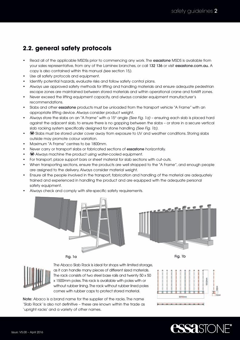
recommendations.• Slabs and other essastone products must be unloaded from the transport vehicle “A Frame” with an
appropriate lifting device. Always consider product weight.• Always store the slabs on an “A Frame” with a 15° angle (See Fig. 1a) – ensuring each slab is placed hard
against the adjacent slab, to ensure there is no gapping between the slabs – or store in a secure verticalslab racking system specifically designed for stone handling (See Fig. 1b).
• Slabs must be stored under cover away from exposure to UV and weather conditions. Storing slabsoutside may promote colour variation.
• Maximum “A Frame” centres to be 1800mm.• Never carry or transport slabs or fabricated sections of essastone horizontally.• Always machine the product using water-cooled equipment.• For transport, place support bars or sheet material for slab sections with cut-outs.• When transporting sections, ensure the products are well strapped to the “A Frame”, and enough people
are assigned to the delivery. Always consider material weight.• Ensure all the people involved in the transport, fabrication and handling of the material are adequately
trained and experienced in handling the product and are equipped with the adequate personalsafety equipment.
• Always check and comply with site-specific safety requirements.
W
W
The Abaco Slab Rack is ideal for shops with limited storage,as it can handle many pieces of different sized materials.The rack consists of two steel base rails and twenty 50 x 50x 1500mm poles. This rack is available with poles with orwithout rubber lining. The rack without rubber lined polescomes with rubber caps to protect stored material.
Note: Abaco is a brand name for the supplier of the racks. The name‘Slab Rack’ is also not definitive – these are known within the trade as‘upright racks’ and a variety of other names.
Issue: V5.00 – April 2016
2.2. general safety protocols
safety guidelines 2
Fig. 1a Fig. 1b
3. applications
applic
atio
ns

essastone is suitable for interior applications. Exposure to direct sunlight for extended periods can causecolour fading which is a condition excluded from the essastone limited warranty.
essastone can be used for: kitchen and vanity benchtops, splashbacks, furniture components, internalcladding, wet-area partitioning, flooring, stairwells, fireplace surrounds, and many other interior vertical andhorizontal applications.
Note:When used for splashback applications, the installation must conform to the minimum Australian/NewZealand Standards for installation behind gas cook tops, for clearances in relation to appliances generatingheat. Please refer to AS/NZS 5601 Gas installations and AS/NZS 4386 Domestic kitchen assemblies – Installation.In flooring applications ensure that the slip requirements relate to your state or territory are understood andmet.
W
Issue: V5.00 – April 2016
applications
3.1. interior applications
applications 3
essastone quartz surfaces are not recommended for use in exterior applications where the product isexposed to direct sunlight outside the roof area, and its use in these applications will void the limited warranty(See Fig. 2). Direct roof area is that which is covered by the formal roofline of the property. Vergola or similaropening roof applications, acrylic sheeted roof products, sail &/or textile coverings are not considered aformal roof for this application.
W
3.2. exterior applications
essastone insideroof line
Alfresco Area
essastone outsideroof line
Fig. 2

4. product specifications
pro
duct s
pecific
atio
ns

essastone quartz surfaces are composed of natural quartz and silica based aggregates, high quality resinsand pigments to provide a non-porous homogeneous material.
Note: The actual composition of each stone slab will vary marginally between colours due to the quartzparticulate design and dimensions.
Issue: V5.00 – April 2016
product specifications4.1. product composition
product specifications 4

5. inspectionidentification/logistics
inspectio
nid
entific
atio
n/lo
gis
tics
Prior to delivery, all essastone products are subjected to many visual and mechanical inspections to ensurethe highest quality standards are met. However, it remains the responsibility of the fabricator to conducttheir own visual and other quality control inspections before accepting the material. If collecting essastonefrom Laminex or receiving a delivery from Laminex, it is essential that before the goods are accepted a visualinspection is carried out. This visual inspection should be carried out in good light conditions.
Goods should be inspected with any protective plastic film removed before processing. Small defects canbe disguised with the plastic film intact and will not be recognised as a claim if the plastic is not removed forinspection. The protective film should not be left on the surface of the essastone for extended periodsparticularly if exposed to UV conditions through adjacent window as this may cause discolouration of thestone surface.
Before commencing the fabrication, check for the following:• Correct items (size, colour, thickness, etc)• Consistent colour match (ensure that colours for the same fabrication have the same batch/lot number,
and inspect for colour compatibility) • Defects, such as: chips, scratches, quartz particulate irregularities, excessive pigmentation spots,
unacceptable product deflection (length and width), evidence of transport cracks, general quality of thesurface finish and quality of the edge.
It is extremely important to check each slab prior to the commencement of fabrication for correct batchnumbering, colour compatibility or for any visual defects that may be outside the written specification,
as replacement or compensation for area loss will not be considered once the slabs have been cut.
When inspecting each slab, please keep in mind that essastone products are manufactured from naturalquartz. Variations in colour, pattern and shade will exist, and are unique characteristics that are inherent innatural quartz. Small blotches or “off-colour” particulate or irregular particulate distribution will also occurwith engineered quartz surfaces, and are not considered to be imperfections or defects, and therefore arenot covered under the limited warranty criteria.
However, if it is considered that any of the above surface variations are evident and are excessive,thenconsultation with a representative of Laminex must be undertaken prior to the commencementof fabrication. No claims will be honoured for partly or fully fabricated slabs which are found to havevisual defects.
W
W
W
W
Issue: V5.00 – April 2016
inspection identification/logistics5.1. visual inspection
inspection identification/logistics 5

Laminex has established a unique batch numbering system that makes it easier for fabricators to conductthe slab selection, and manage possible slab colour variation. The batch number is detailed on the label ofeach slab and printed continuously along the back of the slab.
• Y edges should be kept together (labelling of slab edges prior to cutting is recommended)
• X edges should be kept together (labelling of slab edges prior to cutting is recommended)
• Z edges should be kept together (labelling of slab edges prior to cutting is recommended)
• X to Y or X to Z or Y to Z adjacent butting may not always match with consistent colour or agglomerates.
• X to X or Y to Y or Z to Z adjacent butting is preferred and recommended.
Issue: V5.00 – April 2016
5.2. batch/lot identification
inspection identification/logistics 5
Fig. 5a Fig. 5b
For applications where stone pieces are joined together to complete an installation, material from differentbatches should not be used.
Note: Visual/colour variation between batches will not be recognised under the essastone limited warranty.
Whilst the slab grading at the plant is highly regulated in both colour matching and quality inspection, the fabricatoris still required to check for any colour variance between slabs prior to the commencement of any fabrication.
The agglomerate will also vary to some degree in each slab & within each slab & therefore we do notrecommend adjacent installation of opposite sides or ends of the slab.
W
5.3. colour matching from different batches/lots
Example of full slab set-out
Unusable area
Laminationstrips cut
adjacently
X Y
X Z Z Y
XY
Y
X

Laminex is committed to supplying essastone products in good order and condition; however, it is equallyimportant that all personnel involved in the handling of material take the necessary precautions to ensure itsintegrity during all phases of the project.
This includesall essastone slabs (& offcuts if to be reused) must be stored undercover away from UV light whilstawaiting fabrication. Material noted as stored outside at customer's premises will not be subject to the
essastone warranty once cut and installed.• Ensure product surfaces and edges are well protected when transporting, storing, fabricating and
installing essastone.• Take all relevant safety precautions when handling essastone.• essastone slabs must be transported and stored vertically, ensuring the slabs are well supported at the top
and bottom of the storage and racking system. At all times each slab must be positioned hard against theadjacent slab. Failure to comply with these requirements may lead to the slabs bowing or cracking.
• Slabs and components should be loaded and unloaded from transport vehicles with appropriate liftingdevices (See Fig. 6).
• Whilst unloading or handling slabs or components using clamps (See Fig. 7) or any other device, alwaysfollow equipment supplier’s recommendations and ensure relevant safety procedures are followed.
essastone products must be stored under cover awayfrom direct sunlight and external weather conditions, ona storage system that is perfectly level and provides fullsupport to the entire length and width of the slab (SeeFig. 8). This should prevent any warping or edge damageto the slabs whilst in storage. • The slabs should be stored on a series of “A” frames
or vertical racks designed for stone storage.• Slabs must be aligned against each other in
the rack.• When storing products consider ease of access to
slabs to enable adequate visual inspections.• The surface of the slabs should not be exposed to direct sunlight.• Avoid extreme weather or temperature conditions in excess of 55°C.• Slabs should be stored back-to-back or face-to-face to avoid damage to the polished surface.
W
Issue: V5.00 – April 2016
5.4. material handling and storage
inspection identification/logistics 5
Fig. 8
Fig. 7Fig. 6

It is extremely important to take precautionary measures when handling and transporting essastone slabs andfabricated items.
Consider the following points:• Always follow recommended safety procedures when handling essastone.• Where possible use, mechanical equipment, such as a fork lift or a gantry crane to move essastone.
Always consider the material weight (minimum of 55kg per m2) and follow the recommendations of liftingequipment manufacturers.
• Secure all essastone slabs with approved strapping before transportation. When collecting material fromLaminex, Laminex will not be held responsible for securing the load. Ensure the load is properly strappedand secure.
• It is the responsibility of the transport driver to ensure the load conforms to the legal carrying capacity,and restraining requirements of the vehicle. As a guide, the weight of each essastone slab isapproximately 235kg for 20mm thick and 330kg for 30mm thick, plus any additional framing andpackaging equipment, or other unrelated goods that may be on the vehicle.
• All straps and protective devices must remain grit & burr free and be suitable for direct contact with thepolished surface of essastone. Claims for damage due to unsuitable transport straps/chains abradingthe surface of essastone slab will not be recognised.
W
Issue: V5.00 – April 2016
5.5. material transport
inspection identification/logistics 5

6. design guidelines
desig
n g
uid
elin
es

The successful installation and performance of any essastone benchtop will be influenced by the design andconstruction of the cabinets and benchtop supports.
Installation of an essastone benchtop should only proceed if all aspects of the design and constructionconform to all relevant product guidelines and the minimum requirements as described in this manual.• The cabinets must be constructed from solid panels (16mm thick minimum), ensuring the weight transfer
from the benchtop to the floor is carried out through each end or division.• Cabinets should be installed directly to concrete or other solid floor, not onto floating floors to ensure
stability and load transfer. • Rail support is imperative, with both the front and back rails having minimum dimensions of 90mm wide x 18mm thick.• All cabinets must be level to ensure that the essastone benchtop is installed flat and level. Failure to
level the benchtop will void the warranty.
W
Issue: V5.00 – April 2016
design guidelines6.1. cabinet requirements
design guidelines 6
In addition to adequate cabinetry, essastone benchtops require a level and sturdy surface area to supportthe weight of the material. The benchtop support will reduce the risk of the stone warping or cracking underload during normal use. A maximum out-of-level tolerance is 1.5mm per 3000mm.
The top support must be able to take the material weight (55kg per m2 for 20mm, 80kg per m2 for 30mm) plusany additional load the benchtop could be subject to. Typical loads applied to benchtops could exceed100kg per m2. Any appliance weighing more than 5kg should not be supported directly by the essastone butbe adequately supported by the cabinet frames. Cracks occurring in the essastone product will not berecognised where inadequate support of an appliance is found.
When placing a fabricated essastone benchtop onto cabinets, there are two main methods that can beused to provide substrate support: Full Perimeter Support and Full Substrate Support.
6.2.1. full perimeter support (rails) – 20mm and 30mm
The perimeter support method requires the use of rails around the front and back edge of the cabinet andevery 600mm in centres. A board of suitable length should be used for these rails. These can be made from19mm MR (moisture resistant) Plywood, particularly where there is a likelihood of water penetration. However, ifthe application does not have the potential for water ingress, then the use of 18mm MR Particleboard or MRMDF of the same rail width is acceptable.
6.2.2. full substrate support – 20mm
The full substrate support method involves the placement of a substrate under the complete surface area ofthe essastone benchtop. essastone recommends the use of 19mm Plywood, 18mm MR MDF or Particleboard.Full substrate support is not required for 30mm.
W
6.2. benchtop support

6.3.1. spans
Depending on the design and dimension specification for the base cabinets, where the cabinet widthexceeds 1000mm, the inclusion of a full MR Plywood, MR Particleboard or MR MDF substrate is recommended.
6.3.2. dishwashers
To protect against both heat transfer from the appliance andpossible movement, a full width substrate of MR Plywood, MRParticleboard or MR MDF substrate or similar must be employedover dishwasher openings (See Fig. 9). Thermal shock cracks in theessastone benchtop above the dishwasher may occur due todirect contact/heat transfer to the stone.
Failure to correctly install the dishwasher may result in a non compliant installation finding on any resultingthermal damage, where the essastone warranty will not apply.
6.3.3. overhang support
Depending on the project, the design may call for the provision of an overhanging top, such as abreakfast bar. The following chart provides guidelines for designing overhanging benchtop sections.
W
Cracks occurring where overhangs are greater than the tolerances specified and not adequatelysupported will not be recognised under the essastone warranty.W
Issue: V5.00 – April 2016
6.3. span and overhang support
design guidelines 6
overhang size 20mm material guidelines
Less than 300mm No additional support required
300mm and largerThe fitting of vertical support to the floor, such as legs or similar, orsteel bracing beneath the benchtop.
Note: Dishwasher not to scale.
essastone Substrate
Fig. 9
Any overhang exceeding 300mm shall require 10mm thick, 70mm wide steel flat bar or equivalent placed underneaththe bench-top. These should be placed at 600mm centres.
Any overhang exceeding 300mm shall require 10mm thick, 70mm wide steel flat bar or equivalent placed underneaththe bench-top. These should be placed at 600mm centres.
overhang size 30mm material guidelines
Less than 450mm No additional support required
450mm and largerThe fitting of vertical support to the floor, such as legs or similar, orsteel bracing beneath the benchtop.

6.4.1. benchtops
When designing the benchtop layout plan, it is notpermitted to incorporate any one piece “L” or angle-shaped sections, as any undue movement orstressing at the corner bi-section may lead to stresscracking (See Fig. 8. Installation of any L shapebenchtop, which includes any benchtop with a 90degree or square cut out from any external edgewill void the essastone warranty. Cracks that mayoccur in the vicinity of the L shape cut out will notbe recognised as a claim.
6.4.2. cut-outs
The internal corners in cut-outs, must beradiused, and fabricated with the largestradius possible ( diameter), as this is asafeguard against the possibility of stresscracking (See Fig. 11). Any cracks occurringfrom an appliance cut out will be checked fora smooth edge, free of jags and with asuitable radius. Failure to adhere to theserequirements may result in a non-compliantfinding and no warranty will apply.
W
W
Issue: V5.00 – April 2016
6.4. internal corners
design guidelines 6
Fig. 8
Water cool core drill corners before cutting(minimum drill diameter = 12mm)
D
NO NOT Overcut
Fig. 11
One piece “L”-shaped orangle sections not permitted.
Sink Cutout
Infil PieceC
oo
ktop
Cu
tou
t
Join
�Join
Join
Raised Servery Top
Sink Cutout
Co
okto
p C
uto
ut
Heat Expansion
No
He
at Exp
an
sion
Heat from the sun
Stress Points
Stress Points
Raised Servery Top
Stress Points
�
�
�
�
�
�
Fig. 9 Fig. 10

6.5.1. “U”, “L” and angle-shaped fabrications
The placement of joins in any benchtop should be plannedcarefully to ensure optimum performance of the material andprotection against fracturing.
For angle-shaped corner fabrications, such as “L” or “U” shapes,the use of a single piece of stone is not permitted, as the risk ofcracks appearing in the surface increases. No essastonewarranty is offered for any application where an L shape or Ushape piece of stone is installed in one piece.
The preferred method for all internal corner intersections involvesindividual butt-joined benchtop lengths (See Fig. 12).
6.5.2. joint locations for sink and appliance cut-outs
Consideration of the appliance and sink locations is required when evaluating the project plans. This shouldbe carried out prior to the commencement of template manufacture.
Consider the following recommendations: • In an application where the appliance will generate heat (under bench, oven, hot plate, dishwasher), the deck
join is ideally located not less than 150mm from the cut-out (See Fig. 13). Joins are not permitted to be locatedthrough any cutout or immediately above a heat generating device (hotplate underbench oven, oven,dishwasher. To do so will void the warranty for any heat related cracks occuring in the vicinity of the join.
• In an application where an appliance does not generate heat, such as a top mounted sink, joins may beplaced in the cut-out area.
• Irrespective of the appliance to be used, cut-outs should be designed to have a front and back rail.The dimension of the front and back rail should be no less than 70mm. Therefore where an appliancerequirement makes this dimension less than 70mm, consideration should be given to designing deeperbenchtops in these locations (See Fig. 13) or the addition of stronger rail support (e.g. steel or aluminium).Failure to leave a min of 70mm stone rail front and back of any appliance voids the warranty as the areais not sufficiently supported. Any appliance weighing in excess of 5kg shall also require additionalsupport rails around the opening.
W
W
W
Issue: V5.00 – April 2016
6.5. joint location
design guidelines 6
Ideally150mm +
Ideally150mm +
Ideally70mm +
Ideally70mm +
Fig. 13
Recommended methods for fabricating ‘‘L’’ shaped
or angle tops.
Fig. 12
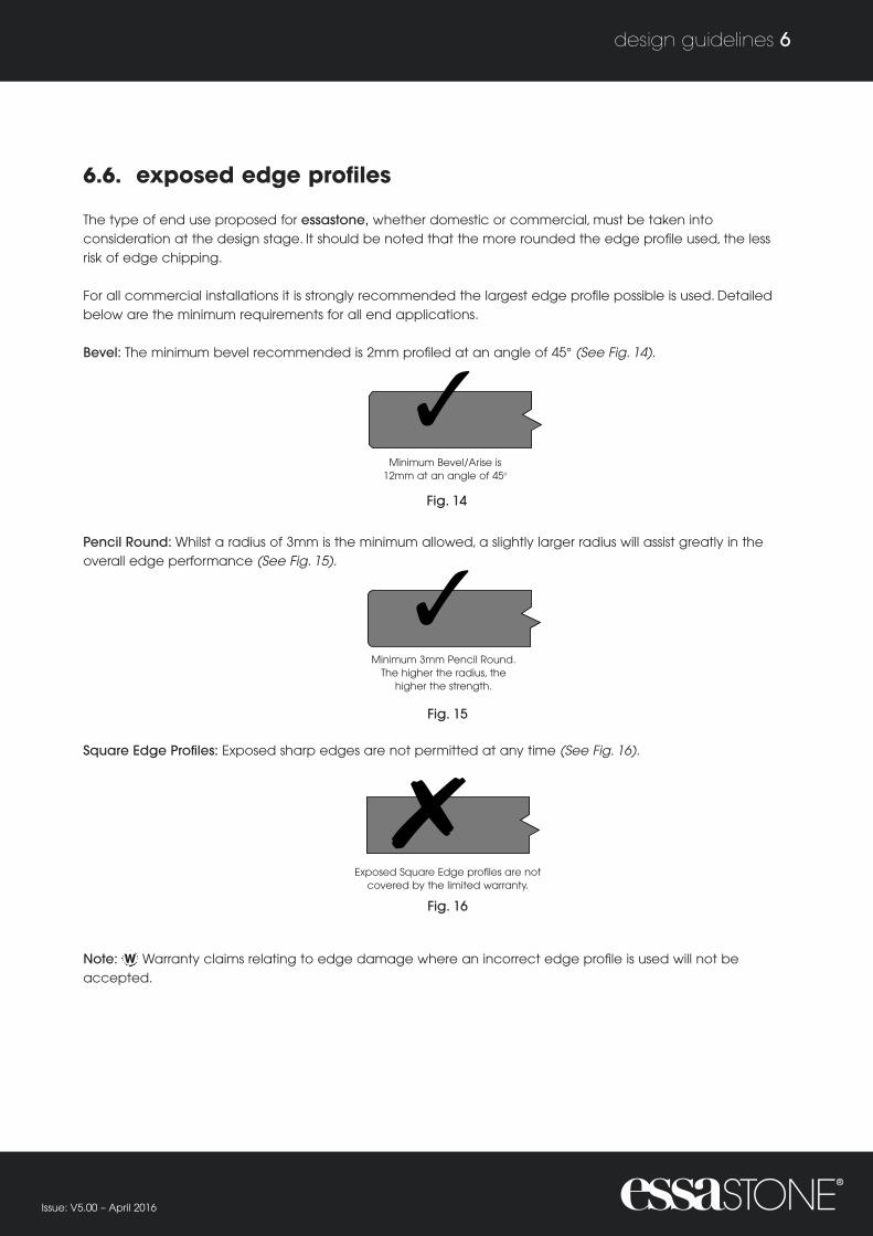
The type of end use proposed for essastone, whether domestic or commercial, must be taken intoconsideration at the design stage. It should be noted that the more rounded the edge profile used, the lessrisk of edge chipping.
For all commercial installations it is strongly recommended the largest edge profile possible is used. Detailedbelow are the minimum requirements for all end applications.
Bevel: The minimum bevel recommended is 2mm profiled at an angle of 45° (See Fig. 14).
Pencil Round:Whilst a radius of 3mm is the minimum allowed, a slightly larger radius will assist greatly in theoverall edge performance (See Fig. 15).
Square Edge Profiles: Exposed sharp edges are not permitted at any time (See Fig. 16).
Note: Warranty claims relating to edge damage where an incorrect edge profile is used will not beaccepted.
W
Issue: V5.00 – April 2016
6.6. exposed edge profiles
design guidelines 6
Exposed Square Edges profiles arenot covered by the limited warranty
Minimum 3mm Pencil Round.The higher the radius the
higher the strength.
E
Minimum Bevel / Ariseis 2mm at an angle of 45º
M
Fig. 14
Fig. 15
Fig. 16
Minimum Bevel/Arise is12mm at an angle of 45o
Minimum 3mm Pencil Round.The higher the radius, the
higher the strength.
Exposed Square Edge profiles are notcovered by the limited warranty.

Variations in ambient temperature will cause wall and cabinet materials to expand and contract.
An expansion gap between the wall and the benchtop is required (See Fig. 17). As a rule, a 3mm to 5mm gapwill be sufficient for normal installations. Expansion gaps of less than 3mm will void the warranty.W
Issue: V5.00 – April 2016
6.7. expansion gap and dimensional tolerances
design guidelines 6
Support rail
Supp
ort r
ail
Rear support rail
Rear
sup
port
rail
supp
ort
Benchtop Wall Substrate
A 3mm to 5mm expansiongap must be present around
the benchtop installation.
Fig. 17
Run
supp
ort r
ail fu
ll len
gth
Supp
ort r
ail

When designing an area where essastone will be used as a splashback, there is a requirement to conform tothe minimum Australian/New Zealand Standards for splashback installation behind gas cook tops. Refer to AS5601 Gas Installations and AS NZS 4386.2 Domestic Kitchen Assemblies-Installation.
The following points should also be considered during the design phase.• Correct distance from a heat-generating appliance to the splashback surface, minimum 200mm from the
edge of a gas burner to the splashback surface.• Correct wall cladding to be installed behind the splashback fixing locations.• Joint line between the benchtop and the splashback should be designed with the use of silicone
adhesive in mind.• All cut outs for GPO's (electrical outlets) must have radiused internal corners and must not occur less than
150mm from any finished edge of the stone. Cracks occuring from square cut internal corners will not berecognised under warranty.
Please note:When installing essastone as a splashback material you must always follow the appropriateAustralian/New Zealand Standards in regard to clearances, especially when installed behind cooktop appliances.
Please refer to the following standards: • AS 5601 Gas Installations • AS/NZS 4386.2 Domestic Kitchen Assembles - Installation • Specific installation requirements as provided by the cooktop appliance manufacturer • Any wall or other construction methods should be conducted in accordance with the relevant industry
guidelines and building codes.
6.9.1. splashback installation requirements
• Electric Cooktops and Induction Cooktops – Installation of essastone as a splashback must be installed with aminimum distance of 50mm from the back edge of the cooktop to the front of the essastone splashback andalso in accordance to any specific installation instructions from the appliance manufacturer (See Fig. 18).
• Gas Cooktops – essastone splashbacks must be installed at a minimum of 200mm from the back edge ofthe rear burners (as per AS 5601) and according to any specific installation instructions from theappliance manufacturer (See Fig. 19).
• All wet areas (kitchens, laundries, bathrooms etc) – install as per your required design and according toAS/NZS 4386.2 Domestic Kitchen Assemblies – Installation. Ensure all joins are adequately sealed withsilicone for waterproofing requirements.
Issue: V5.00 – April 2016
6.8. splashbacks – design considerations
design guidelines 6
6.9. splashbacks – installation
50mm
WALL WALL
50mm
200mm
200mm
WALL WALL
Fig. 18 Fig. 19

6.9.2. splashback installation guidelines
All wall and other construction methods should be as per relevant industry guidelines and building codes. • Timber-framed wall construction should use fibre cement sheeting behind essastone splashback
applications. • Brick wall construction should use cement-based render behind essastone splashback applications.
“L” shapes should not be fabricated in one solid piece, as this does not allow for movement due to thermalexpansion. Cracks occurring from L shape sections will not be recognised under warranty. This includescheck outs around window posts and overhead cabinets.
6.9.3. powerpoint installation
Powerpoint and other item cut-outs must be core drilled to produce radius internal corners minimum of 12mmdiameter. Cross cutting should be avoided at all times (See Fig. 20). Cracks occurring from square cutinternal corners will not be recognised under warranty. Cut outs for GPO/Powerpoint outlets must be at least150mm from the nearest edge of the stone.
The use of silicone is recommended for bonding the splashback to the wall cladding for sealing the joins.
W
W
Issue: V5.00 – April 2016
design guidelines 6
Water cool core drill corners before cutting(minimum drill diameter = 12mm)
Fig. 20

7. preparation, templating and measurement
pre
para
tion, te
mpla
ting
and m
easu
rem
ent
Before any templating, fabricating or installation is considered, it is important that the tradesperson is suitablyexperienced and well aware of the product design requirements. In addition, all relevant information for theinstallation site should be confirmed. It is also important to consider all relevant safety requirements beforecommencing any work.
The initial site inspection should confirm that all cabinets have been adequately installed and fixed.Cabinets must be level in a true plane in every direction.
To eliminate costly errors, the location of electrical, plumbing and any other obvious obstructions that will havean influence on the installation of the essastone benchtop or splashback should be noted on the fabricationplans and templates.
When inspecting the site consider the following: • Accessibility to the construction site, paying particular attention to any obstacles that may create
handling problems during the installation.• Cabinet construction and clearances (refer to section 6 for further details).• All surrounding areas where installation is to occur, particularly where the cabinets have been installed on
existing timber floors. Floors must be stable, rigid and capable of accepting the weight of the essastonebenchtop. The weight of the stone will be 55kg per m2 for 20mm or 80kg per m2 for 30mm plus anyadditional loads. Typical loads may exceed 100kg per m2.
• All cabinets must be adequately fixed to the walls (where free-standing island units are installed they mustbe adequately fixed to the floor and any other part of the rooms’ construction which is to support thefinished installation). Ensure that there is absolutely no movement within the total cabinet installation.
• The installation over floating floors is inherently unstable and is not permitted under the essastonewarranty.
• Electrical and plumbing positioning is located as specified on the working drawings and allows for theinstallation of the essastone benchtop and or splashback. Please check that planned tap holes and cutouts meet the minimum distances descibed in this manual.
• Cabinets and benchtop substrate/support meet the minimum essastone specifications as described insection 6 of this manual.
• Availability of sink(s), cook tops and any other appliances that are to be installed into the benchtop.
W
Issue: V5.00 – April 2016
preparation, templating and measurement7.1. general guidelines
preparation, templating and measurement 7

During the site preparation, either at the time of templating or installation, one of the most important tasks is toensure all the cabinets are levelled. Do this by using a long straight edge. Accurate levelling will help preventstress cracking of the essastone benchtop. • Cabinets must be installed on a true (same) plane.• Cabinets must be levelled to a maximum variation of 1.5mm over a 3000mm run.
Note: Variations up to 1.5mm can be corrected by packing the benchtop to the cabinets, preferably with a dense material (See Fig. 21). Should a level variation exceed 1.5mm over a 3000mm run, or if any other cabinet installation problem is detected at this stage, ensure this is rectified well before the bench-top installation.
Issue: V5.00 – April 2016
7.2. levelling
preparation, templating and measurement 7
Silicone Packing
Fig. 21a

Once design templates have been produced, it is important to check that all the major requirements havebeen met, including:• Accessibility to the construction site.• Cabinet construction, fixing and levelling meets the minimum requirements.• Electrical and plumbing positioning is acceptable.• Substrate and overhang supports are adequate.• Appliance cut-out specifications have been confirmed and cut-outs align correctly.• Where splashbacks or vertical panels are to be installed, ensure correct wall cladding has been fitted, and
comply to the relevant standards.
Ensure that the benchtop support meets all design requirements listed in section 6. Installation should notproceed if support for the benchtop is inadequate.
Warranty claims will not be recognised where insufficient support mechanisms contribute to the failure ofthe essastone material.W
Issue: V5.00 – April 2016
7.3. key considerations
preparation, templating and measurement 7

8. adhesives
adhesive
s

Due to the requirement for the slab to move with materials affected by atmospheric change or exposure toheat from appliances or utensils, the use of a flexible glue line is required for bonding between the substrateand the essastone benchtop components.
Therefore the only adhesive recommended for this application and the application of splashbacks is neutralcure silicone, ensuring there is an adhesive thickness of approximately 1.0mm to allow easy movementbetween the substrate and the benchtop slab once cured (See Fig. 22).
Issue: V5.00 – April 2016
adhesive method to substrate8.1. substrate – benchtops
adhesives 8
Indicates neutral cure silicone adhesive application
Sink Cutout
Co
okt
op
Cu
tou
t
Fig. 22

9. fabrication
fabric
atio
n

Failure to comply with the standards set out in this manual will void warranty claims. However, if you arerequired to fabricate a design or application not covered in this manual, consult with your essastonerepresentative to obtain advice on the proposed fabrication techniques that could satisfy thedesign/fabrication requirements, and retain the 15-year limited warranty.
Always consider safety guidelines when fabricating essastone.
Issue: V5.00 – April 2016
fabrication9.1. basic guidelines
fabrication 9
As with all products, it is advisable to consult with your machinery and tool suppliers to obtain the best cuttingtools for your specific stone working machinery, and conduct testing with these suppliers before commencingany new and untried fabrication applications.
Cutting must be carried out using water-cooled equipment. Evidence of dry cutting will void the essastonewarranty. For cut outs that are unavoidable at the site of installation, it is essential that these are water cooled.Dry cutting leads generates excess heat within the cutout area and may lead to cracking. Evidence of drycutting failures will not be supported by the essastone warranty.
W
9.2. cutting

All cut-outs for sinks and appliances should be completed in the factory environment where a water-cooledprocess can be employed. Water-cooled cutting is essential.
9.3.1. cut-outs – factory made
• Determine the cut-out dimensions, ensuring there is at least 3mm clearance around the entireappliance perimeter.
• Depending on the appliance flange allowance, allow for the internal corner radius to be as large aspossible. A 6mm radius (12mm diameter core drill) should always be the smallest radius (See Fig. 23).
• The finished machined cut-out edges should be as smooth as possible.• Any appliance installed into the essastone material weighing greater than 5kg will require additional
support rails around the underside of the opening.• Evidence of cross cutting, square non radiused corners or jags left behind that contribute to cracks
occurring from within the cutout will not be recognised under warranty.
W
Issue: V5.00 – April 2016
9.3. cut-outs
fabrication 9
NO NOT Undercut NO NOT Overcut
W
Water cool core drill corners before cutting(minimum drill diameter = 12mm)
D
NO NOT Overcut
W
Water cool core drill corners before cutting(minimum drill diameter = 12mm)
NO NOT Overcut
W
Water cool core drill corners before cutting(minimum drill diameter = 12mm)
Hot Plate
Cut-Out
Top Support Top Support
70mm + Cooktop Cut-Out 70mm +
Silicone PackerSiliconePacker
Fig. 23a
Fig. 24
Fig. 23b
Fig. 23c

9.3.2. cut-outs – on-site
It is suggested that the following points are taken into consideration before performing on-site cut-outs.• Cutting on site should be kept to a bare minimum and if possible avoided.• Use all the necessary safety equipment and take all the necessary precautions.• Only experienced installers should perform on-site cut-outs.• It is essential to use water-cooled tools to avoid overheating of the slab and to avoid dust.• Place fully on support, such as old slab/off-cut and drill/cut completely through top piece. • Determine the location for the cut-out and affix masking tape to give a clear line at the cut location;
the tape will also assist in reducing the chance of edge “chip out” (See Fig. 25).• Select the largest diameter core drill and drill the four internal corner locations. (Minimum 6 mm radius)
(See Fig. 26).• Cut along the marked lines with the water-cooled appropriate stone tool, ensuring the cut is made
towards the internal core hole.• Smooth out any rough cutting along the cut-out edges (See Fig. 26).
Note: Ensure that the saw cuts do not run past the internal corner radius. Stress cracks linked to cross cuts,jags or roughly sawn uneven edges will not be accepted under the essastone limited warranty (See Fig. 27).W
Issue: V5.00 – April 2016
fabrication 9
DO NOTcrosscut or undercut
corners
Fig. 25
Fig. 27
Water cool core drill corners before cutting(minimum drill diameter = 12mm)
D
Fig. 26
Water cool core drill corners before cutting(minimum drill diameter = 12mm)

9.4.1. benchtops
When designing the benchtop layout plan, it is not permitted to incorporate any one-piece “L” or angle-shaped sections as undue movement or stressing at the corner bi-section may lead to stress cracking.The corner radius must be 6mm or more (See Fig. 28). No check outs around window posts, upright cabinets,high tops or similar resulting in a 90 degree or L shape cut out are permitted in one piece. Cracksoccurring from the corner of any such installation will not be recognised under warranty.
9.4.2. cut-outs
The internal corners in cut-outs must be radiused and fabricated with the largest radius possible(minimum 6mm radius), as this is a safeguard against the possibility of stress cracking.
Note:When core drilling for internal cut-out corners, the use of water as a cooling agent is required (See Fig. 29).
W
Issue: V5.00 – April 2016
9.4. internal corners
fabrication 9
Recommended methods for fabricating ‘‘L’’ shaped
or angle tops.
Fig. 28
Fig. 29
One piece “L”-shaped or anglesections not permittted.
Approved methods for fabricating “L”-shaped
or angle tops.
Water cool core drill corners before cutting(minimum drill diameter = 12mm)

9.5.1. laminations
When the design of the edge is larger than 30mm in thickness, there are strict guidelines to follow in both thejoin design and location. These are detailed below.• Ensure the strip to be laminated is obtained from the same slab batch, preferably obtained from an
off-cut from the same slab (See Fig. 30).• Always use 45° mitres for all corners (See Fig. 31).• To reduce the chance of joint detection, where possible, all lamination should be of the same length as
the benchtop section. • If the lamination has insufficient length to the benchtop, whilst not preferable, any butt join must have a
45° mitre (See Fig. 32).
Joins not recommended are: • Corner butt joins – corner mitre joins are recommended (See Fig. 33).• Butt joins along the length of the build-down – mitre joins along the length (See Fig. 34).
When the edge profile design allows, we strongly recommend a mitred edge build-up in place of anylaminations exceeding 40mm (or 60mm if using 30mm thick material) in depth. • Where the lamination edge is to be bonded on its edge to the benchtop, then the edge and face
component should be mitred at 45° profile. The edges to be bonded must be machined smooth toreduce the chance of detecting the glue line after fabrication.
• Variations in the colour, thickness or appearance of the glue line in a laminated edge, or failures inbonding are related to fabrication and are not recognised as a product fault in the essastone warranty.W
Issue: V5.00 – April 2016
9.5. edge profiles
fabrication 9

Issue: V5.00 – April 2016
fabrication 9
Not recommended
N
Not recommended
E
Where overall length isin excess of 3l/m, laminated
edge must be mitred at butt join
Exposed end detail. Use mitre joins for all corners.
W
le a
Fig. 30
Fig. 35a
Fig. 31
Fig. 33
Fig. 34
Where possible, use full length lamination.
Where overall length is in excess of 31/m, laminated
edge must be mitred at butt join.
Mitered Join
Fig. 35b
Square Edged
9.5.2. waterfall ends
essastone is not self supporting on the vertical axis. No waterfall end in stone not affixed to the cabinetsshould be used as a support mechanism for a benchtop.
This is the method for the fabrication of waterfall ends.
Both methods require accurate measurements to ensure tensioning of the join is prevented. The waterfall end
must be glued to the side of the cabinet and the load transferred fully to the floor.
Waterfall ends cannot be installed on floating floors due to the potential of movement, which may result in
opening of the joins or cracking of the benchtop. Waterfall ends must only be glued to the floor using neutral
cure silicone to allow for flexibility. Evidence of hard set epoxy style adhesives will void any claims for
cracking occurring due to rigid installation.
Any GPO (electrical outlet) cutouts in a waterfall end must have
a radius in all 4 internal corners, and be set at least 150mm from
the top (horizontal) edge and 150mm min from all vertical edges.
Cracks which occur where these minimum standards are not
employed will not be recognised as a claim.
W
W
Support
Fig. 32
Min. 150mm
Min.150mm

The use of water-cooled polishing tools is essential, as any excessive heat generated will weaken the physicalstructure of the material, as well as giving a dull, flat and/or chalky appearance to the finished polishededge profile and avoid generation of dust particles.
In general, the quality of the machined profiles will ultimately determine the grit sequences to be used, butconduct a trial first with a full set of grits, to ensure finish is acceptable.
Finished profile must be within acceptable tolerances, size and finish.
Note: It is essential to gradually process through the grits listed above. If short cuts are employed by jumpingover grit size sequence, the final polished finish will show scratches and appear dull. Consult with machine andpolishing disk manufacturers for further advice.
For edge polishing of non gloss essastone surfaces please refer to technical bulletins and updates issued byLaminex for this purpose.
Issue: V5.00 – April 2016
9.6. edge polishing
fabrication 9

10. sinks, cook tops, appliances and
washing machine/dryers
sin
ks, c
ook to
ps,
and a
pplia
nces

Before the commencement of the fabrication it is important to have the sink that will be installed in the final
installation available, to obtain the cut-out dimensions, and to confirm that the sink can be located in the
designated cabinet.
Regardless of the square corners of some sink designs, the cut out must employ the radius corners as
detailed below. Failure to do so will void any claims for cracking from the sink precinct.
Drop in or under-mount sink openings of 600mm wide or greater must employ additional under-bench rail
support on all 4 sides. Support rails must be minimum of 19mm MR Plywood
10.1.1. drop-in sinks• Cut-out rail width dimensions should not be narrower than 70mm at both the front and rear of the
benchtop (See Fig. 37 a and b). • The quality of the machined cut-out must be smooth and have a minimum internal corner radius of
6mm (See Fig. 38).• Care must be taken with the sink clip design, as mechanical fixing into the underside of the slab is
not permitted.• Any holes for independent taps, water filters or similar devices must be a minimum of 50mm from the
closest side of the hole to the closest edge of the sink opening. • Cracks occurring where these minimums are not met will not be recognised.
W
W
Issue: V5.00 – April 2016
sinks, cook tops, and appliances10.1. sinks
sinks, cook tops, appliances and washing machine/dryers 10
SiliconeSilicone
70mm + 70mm +essastone rail essastone rail
S
Fig. 38
Fig. 37aThe larger theinternal corner
radius, the greaterthe strength.
SiliconeSilicone
70mm + 70mm +essastone rail essastone rail
Wall
Silicone
Wall Support
Substrate Support Substrate Support
Fig. 37b

10.1.2. under-mount sinks
Whilst the installation instructions are very similar, there are three additional requirements for the installation of
an under-mount sink (See FIg. 39b).
• With under-mount sinks, there is usually a requirement to machine the tap hole or holes through the slab,
therefore sufficient room must be designed into the sink back rail to ensure adequate strength. A minimum
set back of 50mm between the sink cut-out and the closest edge of the tap hole is required to maintain
structural integrity of the benchtop. If more than one hole is to be machined, then it is preferable to
fabricate additional strengthening support under the benchtop.
• The exposed edges of the sink cut-out must be machined and polished to the quality of the fabricated
edges and slightly arrised around the bottom face.
• Prior to locating and bonding, place locating blocks around the sink perimeter with hot melt adhesive,
to ensure the sink does not slip out of position when clamped.• Any holes for independent taps, water filters or similar devices must be a minimum of 50mm from the
closest side of the hole to the closest edge of the sink opening.
Note: All drilled holes and exposed edges must have clean smooth edges.
Issue: V5.00 – April 2016
Silicone
Timber LocatingBlock
Silicone
Timber LocatingBlock
70mm + 70mm +essastone rail essastone rail
S
Fig. 39a
sinks, cook tops, appliances and washing machine/dryers 10
10.2. laundry tubs & taps
Applications in laundry installations vary widely. There is a typical use of 45 litre tubs which when filled weigh
50kg approx. essastone surfaces are not a construction material and are not designed to support this weight
without the cabinets being reinforced. Supporting cabinet rails must be employed around all laundry tub/sink
openings to assist the weight distribution.
Where double bowls/tubs are installed, front to back vertical support rails underneath the bench-top must be
used to support the weight. 19mm MR plywood is recommended.
Where the essastone is required to span across an opening greater than 600mm (eg across under-bench
appliances or double tubs), additional upright vertical support rails in the cabinet must be used. Failure to
support the material adequately will result in no recognition of claims from cracks occurring in the area.
All stone rails between and in front and behind laundry tub cut-outs must be a minimum of 70mm wide.
Independent tap holes must be a minimum of 50mm from the sink edge to the closest edge of the tap hole
and a minimum of 70mm from the closest edge of the bench-top. Cracks occurring from fixtures not
employing these minimum widths will not be recognised.
W
W

Issue: V5.00 – April 2016
sinks, cook tops, appliances and washing machine/dryers 10
10.3. washing machine/dryer installation
essastone is not suitable to be used as a support to on-bench appliances due to excessive weight and heatgenerated.
Wall Fixed Dryers should be wall mounted well away from the essastone bench-top – a minimum distance of
450mm is required.
Under-bench Dryers need to be considered carefully as substantial heat generation occurs when in use.
Some appliances exhaust heat from the front of the unit, whilst others are from the back or ducted.
The use of under bench washing machine and/or dryers requires a substrate to be employed above the
appliance to protect from direct heat and thermal load underneath the essastone bench top in the same
manner as for a dishwasher. Thermal shock may occur if protection is not provided, and resulting cracks
from this condition are not recognised under the essastone warranty.
W
Fig. 40 SupportPanels
Vertical Supportat the junction ofthe cabinet doors
600mmMaximum
Front to back railbetween bowls
to support weight
Vertical Rail

Issue: V5.00 – April 2016
10.4. external use barbeques
essastone can be used in external applications where a gas or electric inbuilt BBQ is used, with strictadherence to the following requirements:
• The installation must not be in direct sunlight outside the roof area, it is only permitted in alfrescoapplications inside the roof line (See Fig. 2)
• All makes and specifications for BBQs are different, and the heat output will vary with the manner in whichthey are used, the energy output from the burners and whether the BBQ has a hood or not. No BBQ, Plate,Grill or heating apparatus can come into direct contact. with the essastone benchtop. The BBQ must bemounted using isolated metal mounting points supported entirely by the cabinet frame, not from thebenchtop.
• A minimum air gap of 10mm must beobserved around all BBQ installations toprevent conduction of energy into theessastone and to allow for adequateventilation. Failure to maintain this gap mayresult in heat cracks, which are not coveredby warranty.
• A stainless steel or ceramic trim (minimumwidth 25mm) should be installed around theperimeter of the BBQ (without directcontact to the BBQ itself) to assist inreflecting or reducing radiated heat awayfrom the essastone benchtop.
• Heat protective mats (ceramic trivets,wooden cutting boards etc) must be usedto rest hot platters or cast iron grills. Theseshould be positioned on the surface of thestone immediately adjacent to the cookingsurface to protect against thermal shock.
Damage due to thermal shock around aBBQ is not warranted.
• No temperature exposure to essastoneshould exceed 70° above ambienttemperature.
• essastone may not be used underneath theBBQ or heating/cooking device and maynot be used to line the upright sidesadjacent to either side of the BBQ unless amin gap of 100mm is employed from thefront face of the essastone to the closestedge of the BBQ.
• Where multiple cut outs are required for sideby side grill/cooking panels, a minimum railof 70mm must be left between each cutout. Additional rail supports must beprovided for any individual applianceweighing greater than 5kg.
W
Stainless steel or
ceramic trim(25mm min
width)
S
Minimum front rail
width 70mmInbuilt design, no front access
Air gap, minimum
10mm
A
Fig. 41a
Stainless steel or
ceramic trim(25mm min
width)
M
Air gap, minimum
10mm
Inbuilt design, front controls
Fig. 41b
Air gap, minimum 10mm
Mounting brackets
Stainless steel orCeramic trim
Fig. 42
sinks, cook tops, appliances and washing machine/dryers 10

11. installation
insta
llatio
n

The following should be carried out prior to installation:
• Check, measure and ensure the correct cabinets are in their correct locations.
• Ensure all cabinets are level and on a true (same) plane.
• Ensure good weight transfer from the top through the ends (gable) or divisions to the floor.
• All cabinets must be firmly attached to the wall/s, and island cabinets must be well fixed to the floor.
• Cabinet rails meet the minimum specifications.
• Adequate benchtop support is in place.
Note: Should the benchtops be installed on evidently non-complying cabinets and the stone installation
fails, no post-installation warranty claims will be recognised by Laminex. Check sections 6 and 16 of this
manual for further details.
Installation to be completed with silicone blobs as per Fig. 43.
W
Issue: V5.00 – April 2016
installation
installation 11
Indicates neutral cure silicone adhesive application
Sink CutoutC
oo
kto
p C
uto
ut
Fig. 43

12. repairs
repairs

Whilst handling the material during the fabrication, transportation and installation, there is the risk of minor
damage occurring. Therefore, it is important to take all the necessary precautions to eliminate this risk.
Should minor handling damage occur, the following points may assist in carrying out minor repairs, which are
only authorised on the fabricated edges and faces of the essastone. No repairs, fill or repolishing to the
factory supplied (original finished essastone surface as supplied by Laminex) is authorised and to do so
without consultation will void any claims under warranty arising from the result.
Laminex maintains an endorsed group of specialist technicians (non stone masons) that are used for minor
repairs and repolishing under warranty conditions. Please report any non standard condition of the original
finished essastone surface before cutting and processing to your local essastone representative.
W
Issue: V5.00 – April 2016
repairs
repairs 12

13. care and maintenance
care
and
main
tenance

routine care and maintenanceFor routine cleaning, use small quantities of non-bleach, non-abrasive cleaners together with warm water anda damp cloth or sponge. Liquid spills including fruits, vegetables, food colourings and curries, should be wipedup immediately and cleaned with a mild detergent and water immediately after detection.
preventing heat damageProtective trivets and heat pads must always be used underneath cookware such as skillets, saucepans, potsor dishes when removing hot items directly from any heat source (oven cooktop or microwave) and placingonto the essastone surface. Prolonged or sudden extreme temperature changes can create thermal shockcracks which are excluded from the essastone warranty.
It is recommended that stone fabricators inform all trade customers, builders and consumers of the risk ofthermal shock as it is a common misconception that stone can withstand high temperatures.
Additional care should be taken around hotplates as oversize cooking accessories (eg extra wide frypans)can overhang the appliance and conduct radiant heat directly onto the surface of the stone, risking thermaldamage.
preventing scratchesThe use of cutting boards and taking care not to drop or move heavy objects on the surface will help toensure the long lasting beauty of essastone. The resilient surface of essastone has been designed to withstandnormal daily use. Whilst it is resistant to scratches, cuts and chipping, do not cut directly on the essastonesurface. Scratches and chips to the edge or primary surface of essastone are not protected under warranty.
preventing chemical damageThere are some strong chemicals and solvents that can cause damage to essastone. Paint remover, paintand stain strippers, nail polish removers, concentrated bleach (such as undiluted Domestos), furniturecleaners, oil soaps, permanent markers or inks, oven cleaners, drain cleaners and chemicals with high alkalinepH levels are examples of products that could damage the surface. If a strong chemical or solvent comes intocontact with your essastone surface, rinse immediately with plenty of water then follow with normal cleaningprocedures. Evidence of chemical damage or colour change is not protected under warranty.
removing difficult spills and stainsFor gloss surfaces, if routine cleaning procedures do not remove stubborn or dried spills/stains, use a non-abrasive cleaning pad such as a household sponge, along with a glass and surface cleaner. Should chewinggum, nail polish, or similar substances adhere to the surface, they can be removed with a plastic scraper.Gently scrape off the substance, then follow the routine cleaning procedures listed above.
Please note: many cream cleansers have been found to contain abrasives that may damage the polishedsurface of essastone and are not endorsed for use.
For matt/honed/textured surfaces (NOT GLOSS), if routine cleaning procedures do not remove stubborn ordried spills/stains, the careful use of ‘Jif Cream Cleanser with micro-particles’ can be used in conjunction withthe following procedure. The essastone surface must be wet with water and a small amount of ‘Jif CreamCleanser with micro-particles’ applied with a damp soft cloth. Only use light pressure and clean with a swirlingmotion. Keep the area wet with small amounts of water to allow the fine cleaning particles to gently removethe stain. Wash and wipe the surface to remove the cleaning agent and dry with a soft cloth.
For all surface finishes, red wine and other tannin based stains can be removed with a diluted bleach solution(a 50:50 mix of ‘Domestos Regular cleaner’ and water). Do not allow the bleach to remain on the surface forlonger than one minute. Wash with water to remove the diluted bleach and dry with a soft cloth. Repeat theprocess with the diluted bleach if not successful.
For all surface finishes, should paint spots/stains persist after following the above procedures then, as a lastalternative, the spot use of acetone may be successful. However, colour change or surface damage resultingfrom the use of acetone is not recognised under warranty, so this should be used as a last resort. Testing on aninconspicuous area first is highly recommended.
General comments essastone requires no sealing or special cleaning products. essastone is made fromnatural quartz, therefore variations in colour and patterns may occur. Small surface spots and blotches aretypical in engineered quartz surfaces.
For more information visit essastone.com.au or call 132 136.
Issue: V5.00 – April 2016
care and maintenance
care and maintenance 13

14. key considerations foryour essastone project
Key c
onsid
era
tions fo
r yo
ur e
ssasto
ne p
roje
ct

• If you are in the planning and design stage of your essastone project there are some important points that
you should consider to ensure your beautiful essastone installation meets the compliance requirements for
the essastone warranty.
• ‘The Design Guidelines for essastone’ is a separate document found on the essastone website
www.essastone.com.au which provides a more detailed set of information to assist.
A quick checklist:
• Are my cabinets built suitably for a stone surface? Minimum support rails and maximum unsupported
overhangs on breakfast bars apply.
• Is there a substrate panel installed over my dishwasher opening to ensure the thermal load from the
appliance does not damage the stone?
• Is the minimum distance (50mm) used between any tap holes and the nearest sink or basin opening?
• Is the minimum distance (70mm) used for any front/back rails of my sink or hotplate cut out?
• Has the countertop been designed to avoid any “L” Shape Benchtops installed in one piece? A join should
be used wherever the countertop changes direction.
• Have I got cut outs around my windows in the kitchen that form an “L” shape or 90 degree cut out in the
stone? (These should be avoided and an extra join used).
• Correctly placed joins in your stone surface act as expansion joints and will protect against cracks forming.
Issue: V5.00 – April 2016
key considerations for your essastone project
key considerations for your essastone project 14

15. warranty
warra
nty

essastone is covered by a 15-year limited warranty. This provides peace of mind to the customer that theirimportant investment is protected for years to come.
essastone is manufactured from natural quartz and silica. Variations in colour, pattern and shade will exist, andare unique characteristics inherent in natural quartz. Small blotches or off-colour particulate (chips) or irregularparticulate distribution will occur in engineered quartz surfaces, and are not covered under the productlimited warranty.
15.1. typical responsibilities of the stone fabricator
The following is a non-exhaustive list of items that will void the essastone limited warranty. These are areas
outside of the control of Laminex. The stone fabricator is cautioned that these areas remain their responsibility
and failure to comply with the essastone fabrication requirements will not be recognised in warranty claims.• Colour variation due to the use of slabs from different lots/batches in the same fabrication.• Obvious faults in the finished fabricated items that were visible in the essastone slab at the
commencement of the fabrication. It is the fabricator’s responsibility to inspect the products beforecommencement of any job.
• Any re-polishing or repair of the original supplied surface finish.• Where insufficient perimeter clearance of at least 3mm on all sides of a bench-top abutting a wall or solid
fixture, including joining to another benchtop.• Failure of the product due to inadequate support of the material.• Installation onto cabinets where the finished essastone surface is out of level by more than 1.5mm per
3000mm length.• Performance issues as a result of design or applications not recommended in this manual or not approved
in writing by Laminex.• Reduced performance as a result of any mechanical reduction in the slab thickness performed by the
stone mason.• Claims for visual appearance of the join line or for inadequate selection/application of adhesives.• Claims for the failure of any adhesive or caulking, whether as a join or otherwise. • Design/applications outside relevant national or local building regulations or that do not comply with
relevant Australian Standards.• General damage through poor fabrication or installation techniques.• The installation of “L”-shaped benchtops, or “L”-shaped cut outs or L shaped sections, or sections installed
in one continuous piece.• The use of cut-outs for any application that do not employ the designated corner radius.• Tap holes installed less than 50mm min from the edge of the sink or laundry tub.• Non-compliance with the essastone fabrication requirements as set in this manual and technical literature
as supplied by Laminex.
W
Issue: V5.00 – April 2016
warranty
warranty 15

Issue: V5.00 – April 2016
15.2.15-year limited warranty general terms and conditions
warranty 15
1 Subject to the conditions and limitations set out
in this warranty below, Laminex Group Pty
Limited, trading as Laminex, warrants to the
original purchaser of essastone products for
interior residential and commercial use that
Laminex will, at its option, repair or replace that
product without charge if it fails directly as a
result of a defect in its manufacture or material
used in its manufacture, during the first 15 years
after initial installation (proof of purchase will be
required). Subject to paragraph 9, this limited
warranty terminates at the expiration of 15 years
from the date of installation of the essastone
product.
2 This limited warranty does not cover any
defect/damage caused by:
(a) any act of God, any natural occurrence or
any other circumstance beyond Laminex’s
control; or
(b) physical abuse, negligence, vandalism,
misuse , accidents, exposure to excessive heat,
exposure to excessive moisture, the use of
solvents or inappropriate cleaning
products/materials, improper maintenance,
exposure to chemical products, and/or
normal ‘wear and tear’, including, without
limitation, fractures, burns, scratches, stains,
chipping, cuts, wipe marks and scuffs on the
product; or
(c) failure to follow the Care and Maintenance
instructions of the product; or
(d) exposure to direct sun light including general
fading and discolouration;
(e) variations in colour, pattern and shade of the
material against the sample material, displays
and/or printed illustrations; or
(f) thermal shock, excessive heat, or excessive
weight;
(g) failure to follow any procedures
recommended by Laminex for the fabrication
and installation of essastone products;
(h) failure of any adhesive, caulk, or other
accessory, or failure of any caulked or filled
joins or seams;
(i) faulty workmanship by any person subsequent
to the supply of the essastone product from
Laminex.
3 This warranty also does not cover:
(a) anything which has been disclosed as a
feature or limitation of the essastone product
in any literature published or distributed by
Laminex; or
(b) outdoor application; or
(c) where the defect is trivial or insubstantial; or
(d) where, as at the date of notification of the
defect to Laminex, the type or colour of the
alleged defective product no longer forms
part of Laminex’s standard stock range and
the person complaining of the defect does
not agree to the supply of a replacement
which is as close a type or colour match as is
possible for Laminex’s then prevailing stock
range.
4 This limited warranty applies only to essastone
colours from the 2010 range which;
(a) have been purchased from Laminex after 1
March 2010, for interior residential or
commercial use in Australia;
(b) have not been moved from their original
place of installation;
(c) have been designed, fabricated and installed
according to procedures recommended by
Laminex in the essastone Technical &
Fabrication Manual and related literature; and
(d) have been installed, maintained, used and
protected in the manner recommended by
Laminex in its published literature concerning
those products, a copy of which may be
obtained, free of charge, from the fabricator
named below or by writing directly to
Laminex at the address given below; and
(e) where Laminex has been notified of the
defect within seven days of the first person to
become aware of it.
5 This limited warranty will cover reasonable labour
charges, which are necessary for the repair or
replacement of any essastone product covered
by this warranty.
6 Laminex may determine that a replacement
product may not be reasonably available in the
same colour or shape as the original essastone
product covered by this limited warranty. If
Laminex determines that a replacement product
of the same colour or shape is not reasonably
available, Laminex reserves the right to provide a
replacement product of as close a shape and
colour match as is reasonably possible from
Laminex’s then current stock range in satisfaction
of its obligations under this limited warranty.
7 Please fill out the attached registration card and
mail directly to Laminex at the address given
below.
8 Except as expressly provided in paragraphs 1
and 9, all terms, conditions, warranties,
undertakings, inducements and representations,
whether expressed or implied, statutory or
otherwise relating to any essastone product are
excluded. Without limiting the generality of the
preceding sentence, Laminex will not be under
other liability in respect of any loss or damage
(including consequential loss or damage)
however caused (whether by negligence or
otherwise) which may be suffered or incurred or
which may arise directly or indirectly in respect
of any essastone product.
9 Where any applicable legislation implies any
term, condition or warranty in Laminex’s
relationship with a person who has acquired any
essastone product, or otherwise gives that
person a particular remedy against Laminex,
and that legislation or any legislation voids or
prohibits any provision excluding, or modifying
the application of, or the exercise of, any liability
under such term, condition, warranty or remedy
shall be deemed to be in or, as the case may
be, apply to that relationship. However, Laminex’s
liability for any breach of such term, condition,
warranty, or under such remedy, shall be limited,
at Laminex’s option, in any one or more of the
ways permitted by the legislation where so
permitted:
(a) if the breach relates to any essastone
product;
(i) the replacement of that essastone
product or supply of similar product; or
(ii) the repair of that essastone
product; or
(iii) the payment of the cost of
replacing that essastone product with
similar product; or
(iv) the payment of the cost of having
the essastone product repaired; and
(b) if the breach relates to services:
(i) the supply of the services again; or
(ii) the payment of the cost of having
the services supplied.
10 Please note that the law may confer on you
rights arising out of the essastone products in
addition to those set out in this limited warranty.
This limited warranty should therefore not be
read as an exhaustive statement of the rights of
the original purchaser or any person.
11 The warranty does not cover any other product
used or installed in connection with the
essastone product.
12 This warranty is not transferable or assignable.
13 Any questions regarding this warranty should be
addressed to Laminex at the address given
below:
Laminex
essastone Warranties
PO Box 407, Doncaster, VIC, 3108.
16. MSDS – material safetydata sheets
MS
DS
– m
ate
rial
safe
ty data
sheets

Material Safety Data Sheetessastone Page 1 of 8

Material Safety Data Sheetessastone Page 2 of 8

Material Safety Data Sheetessastone Page 3 of 8

Material Safety Data Sheetessastone Page 4 of 8
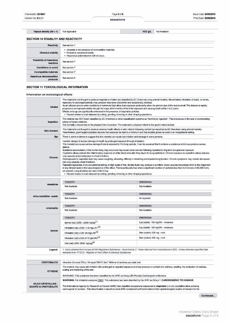
Material Safety Data Sheetessastone Page 5 of 8

Material Safety Data Sheetessastone Page 6 of 8

Material Safety Data Sheetessastone Page 7 of 8

Material Safety Data Sheetessastone Page 8 of 8