fabrication and qualification procedure for multi-project...
TRANSCRIPT

Departmental Materials Specification DMS-7305
Materials and Tests Division 1 – 30 Effective Date: January 2019
DMS-7305
Fabrication and Qualification Procedure for Multi-Project Fabrication Plants of Precast Concrete Drainage Structures Effective Date: January 2019
1. DESCRIPTION
This Specification governs the fabrication requirements and qualification processes for fabrication plants producing precast concrete drainage structures listed in Article 7305.4 of this Specification for Department projects. Precast concrete drainage units must meet the requirements of this Specification and the pertinent Items of the Department’s Standard Specifications for Construction and Maintenance of Highways, Streets, and Bridges.
2. DEFINITIONS AND ABREVIATIONS
The following definitions apply to this Specification.
ACI. American Concrete Institute.
ACPA. American Concrete Pipe Association.
Cosmetic Damage. Any damage with a maximum depth of 3/8 in.
Diameter. The internal diameter of round pipe. For arch and elliptical pipe reference Item 464, “Reinforced Concrete Pipe,” to determine the design size using the equivalent diameter.
Design Strength. The minimum concrete compressive strength at 28 days.
Dry Cast Concrete. Fresh concrete having a relative zero slump.
Engineer. The Chief Engineer of the Department or the authorized representative of the Chief Engineer.
Formed Precast Units. Precast drainage units fabricated with wet cast (conventional or SCC) concrete.
Machine-Made Precast Units. Precast drainage units fabricated with dry cast concrete.
Multi-Project Fabrication Plant. A facility at an offsite location fabricating precast members. This definition also applies to single-contract offsite facilities.
NPCA. National Precast Concrete Association.
Precast Units. Precast drainage units fabricated by a process utilizing either dry or wet cast concrete.
Self-Consolidating Concrete (SCC). Wet cast concrete meeting the slump flow requirements of Item 421 and is highly workable, flows through densely reinforced or complex structural elements under its own weight, and adequately fill voids without segregation or excessive bleeding without the need for vibration.
Temperature Probe. Thermocouple for measuring concrete temperature or air temperature.
Temperature Recording Device. Data logger for recording temperatures from the temperature probes.
Wet Cast Concrete. Fresh concrete meeting the placement slump or slump flow requirements of Item 421, “Hydraulic Cement Concrete.”
3. MATERIAL PRODUCER LIST
For the precast concrete drainage structures listed under Article 7305.4, the Materials and Tests Division (MTD) maintains the Material Producer Lists (MPLs) of fabrication plants conforming to the requirements of this Specification. Precast drainage structures produced by fabricators appearing on the applicable MPL

Departmental Materials Specification DMS-7305
Materials and Tests Division 2 – 30 Effective Date: January 2019
require no further Department inspection and testing unless deemed necessary by the Department project engineer or MTD. Precast concrete drainage structures used on Department projects must be produced by fabrication plants listed on the applicable MPL.
4. PRECAST CONCRETE DRAINAGE STRUCTURES
Precast concrete drainage structures include:
Concrete Box Culverts (formed precast and machine-made precast) referenced in Item 462, “Concrete Box Culverts and Drains,”
Junction Boxes, Manholes, and Inlets (formed precast and machine-made precast) referenced in Item 465, “Junction Boxes, Manholes, and Inlets,” and
Reinforced Concrete (RC) Pipe (formed precast and machine-made precast) referenced in Item 464, “Reinforced Concrete Pipe.”
5. BIDDERS’ AND SUPPLIERS’ REQUIREMENTS
Use of pre-qualified product does not relieve the Contractor of the responsibility to provide product that meets this Specification. The Department may inspect or test material at any time and reject any material that does not meet the specifications.
6. PRE-QUALIFICATION PROCEDURE
Pre-Qualification Request. Submit a request for evaluation under DMS-7305 to [email protected]. 6.1.
Include the following information in the request:
company and fabrication plant name;
physical and mailing addresses;
contact person, titles, phone number, and email address;
list of precast products (box culvert, RC pipe, junction boxes, manholes, or inlets);
written plant quality control (QC) and production procedures for each production method (i.e. formed precast or machine-made precast, SCC, vibratory, centripetal, etc.) for each product as defined in Article 7305.4;
list of all on-site QC personnel with copies of current QC certification(s) and a detailed description of their QC related experience, as required by Article 7305.12;
list of welding shops fabricating the supplied welded steel grates and frames (if applicable);
National Precast Concrete Association (NPCA) Plant Certification (Texas Version) (for box culvert and RC pipe fabrication plants). NPCA Plant Certification (Texas Version) is required for fabrication plants of precast concrete junction boxes, manholes, and inlets. Conditional Plant Certification will not be recognized; and
copy of the most recent NPCA audit report, with the Texas addendum included, and written response to any specific deficiencies noted in the NPCA audit report and the Texas addendum. The Engineer must approve any proposed deviations from the specifications required in NCPA plant certification program.
Evaluation. MTD will review the qualification request documentation. If the qualification request includes the 6.2.required information, MTD will perform an initial Department-directed plant audit for each product type to ensure compliance with this Specification. The Department will evaluate all fabrication plants for adequate equipment, processes, production methods, organization, experience, knowledge, and competent personnel to produce specification compliant product.
6.2.1. Qualification. If the required submittals and audit(s) verify compliance with this Specification, the Department will list the fabrication plant on the applicable MPL. This approval is limited to the type of product and production method submitted in accordance with Section 7305.6.1. Discrepancies identified in the audit

Departmental Materials Specification DMS-7305
Materials and Tests Division 3 – 30 Effective Date: January 2019
must be adequately addressed in a manner acceptable to the Department prior to being placed on the MPL. MTD reserves the right to perform additional audits (announced or unannounced) at its discretion for the plant to remain on the MPL as an approved fabrication plant of precast concrete drainage structures.
Fabrication plants listed on the MPL must annually attain and submit the following in order to maintain approval status:
current NPCA Plant Certification (Texas Version) for the applicable precast concrete drainage structures. Conditional Plant Certifications will not be recognized;
copy of the most recent NPCA audit report, with the Texas addendum, included and written response to any specific deficiencies noted in NPCA’s audit report and the Texas addendum;
successful completion of any Department-directed audits and any follow-up plant audits by adequately implementing corrective actions for all deficiencies; and
copies of current QC personnel certifications for on-site QC personnel when changes occur.
Fabrication plants must also perform the following in order to maintain approval status:
maintain the laboratory, equipment, and batch plant in adequate condition to function properly for the intended use; and
perform 2 internal compliance audits per year (summer and winter) using TxDOT furnished audit checklist. Compliance audits must be completed within 14 days from the start of an audit and performed by qualified QC personnel approved by the Department. Consecutive internal audits must be performed at intervals of 5 to7 months. Submit audit findings and corrective actions for each deficiency which must be implemented within 15 days from the completion of the audit.
Failure to promptly comply with the above may result in disqualification, which includes removal from the MPL.
6.2.2. Failure. Fabrication plants not qualified under this Specification may not furnish precast concrete drainage structures for use on Department projects and must show evidence of correction of all deficiencies before reconsideration for qualification.
Random Inspection and Testing. The Department reserves the right to inspect, sample, test, conduct 6.3.random audits and review documentation at any time to ensure compliance with this Specification. Provide facilities and access to allow for inspection of materials, the process of fabrication, and the finished precast concrete drainage structures. Coordinate the scheduling of any inspections the Department requests to perform.
Disqualification. Any fabricator failing to comply with the requirements of this Specification is subject to 6.4.disqualification, which includes removal from the MPL. A disqualified fabricator is prohibited from furnishing product to Department projects and may not bid any work let during the disqualification period. The disqualification period will be a minimum of 30 days or as determined by MTD.
Causes for disqualification and removal from the MPL may include, but are not limited to:
repetitive poor quality and workmanship;
falsification of or incomplete documentation;
lack of certified or qualified QC personnel;
not following approved QC and production procedures; or
certifying or furnishing product not meeting specifications.
If a fabricator has been disqualified, all previously produced products will be subject to review and possible removal from assigned projects. If the Department disqualifies a fabricator, the Department may permit subcontracting remaining product quantities for active projects to another Department-approved fabrication plant for the specific product.

Departmental Materials Specification DMS-7305
Materials and Tests Division 4 – 30 Effective Date: January 2019
Re-Qualification. Once the disqualification period established by MTD has elapsed, the fabricator may begin 6.5.the re-qualification process by providing the Department with an implemented reconciliation plan including, at a minimum:
evidence of corrected deficiencies and corrective measures to prevent reoccurrences;
passing an additional NPCA and Department-directed audit; and
ensuring compliance with all requirements in this Specification.
The disqualified fabricator will bear all costs associated with re-qualification.
Inactive Fabricator. If a fabricator does not furnish any precast concrete drainage structures to Department 6.6.projects for a period of 2 years, MTD may remove the fabricator from the MPL due to inactivity.
MTD will consider future qualification after the fabricator is awarded a Contract to furnish precast concrete drainage structures to a Department project and complies with this Specification.
7. MATERIALS
Aggregate. Maintain aggregates above saturated surface dry condition when using mixer moisture probes. 7.1.Sprinkle and/or shade aggregates as needed.
Concrete. Provide concrete and component materials in accordance with Item 421, “Hydraulic Cement 7.2.Concrete” except as otherwise noted in this Specification. Furnish Class H concrete with the following stipulations:
use one of the mix design Options 1-8 meeting the requirements in Item 421.4.2.6, “Mix Design Options;”
when the cementitious material content does not exceed 520 lbs./cu.yd., Class C fly ash may be used instead of Class F fly ash for mix design Option 1;
use coarse aggregate grades 3-8 for formed precast RC pipe and box culverts;
aggregate gradation requirements will not apply for machine-made precast units; and
proportion the concrete materials with a water to cementitious (w/c) ratio between 0.28 and 0.45 and with an allowable variation during production of ± 0.02 from the approved mix design.
Provide concrete meeting the approved mix design.
When sulfate resistant concrete (SRC) is required, furnish concrete meeting the Class “X” (SRC) requirements listed in Table 8 of Item 421. Do not use Class C fly ash in SRC.
Aggregate hoppers or storage bins for fine and coarse aggregate must be equipped with electric moisture probes for SCC unless approved by the Engineer.
7.2.1. Mixing of Concrete. Volumetric mixers may be permitted if approved by the Engineer. Do not use volumetric mixers for self-consolidating concrete (SCC). Do not place discharged concrete back into the concrete mixer.
7.2.1.1. Formed Precast Units. Mix concrete for a period of 1 min. for 1 cu. yd. and 15 sec. for each additional cu. yd. of rated capacity of the mixer. Count the mixing time from the time all materials are in the drum. Increase mixing time, if necessary, to achieve a uniform mix.
7.2.1.2. Machine-Made Precast Units. Mix concrete for a period of 35 sec. for 1 cu. yd. and 15 sec. for each additional cu. yd. of rated capacity of the mixer. Count the mixing time from the time all materials are in the drum. Increase mixing time, if necessary, to achieve a uniform mix.
7.2.2. Concrete Trial Batches. Provide a work plan, preliminary, and final trial batch data for proposed concrete mix designs per Tex-703-I for precast units.

Departmental Materials Specification DMS-7305
Materials and Tests Division 5 – 30 Effective Date: January 2019
Submit Form PC-342-R for proposed concrete mix designs for all precast units prior to use.
Reinforcing Steel. Provide and store reinforcing steel in accordance with Item 440, “Reinforcement for 7.3.Concrete.” Base metal rod to be cold-drawn for helical RC pipe cage production must comply with Item 6, “Buy America” requirements but does not need to be furnished by a Department-approved reinforcing steel mill.
Hydraulic Cement Concrete Curing Materials. Furnish concrete curing compounds conforming to 7.4.DMS-4650, “Hydraulic Cement Concrete Curing Materials and Evaporation Retardants.”
8. FABRICATION
Provide precast drainage structures conforming to the design shown on the plans and to the following, except as otherwise noted in this specification:
ASTM C 76 or ASTM C 655, unless otherwise shown on the plans, for circular pipe,
ASTM C 478 for circular reinforced manhole structures,
ASTM C 506 for arch pipe,
ASTM C 507 for horizontal elliptical pipe, and
ASTM C 1577, for box culverts, unless otherwise shown on the plans.
Maintain on file Department-approved shop drawings for precast drainage structures when required.
Equipment. 8.1.
8.1.1. Batch Plant. Provide concrete plants and mixing equipment, hauling equipment, and testing equipment in accordance with Item 421.3, “Equipment.” Truck mixers are not permitted for machine-made precast units. Volumetric mixers will not be permitted unless approved by the Engineer. Check batching accuracy of volumetric water batching devices in accordance with National Ready Mixed Concrete Association (NRMCA) guidelines.
8.1.2. Forms. Maintain forms free from dents, grease, or other foreign materials that may affect the appearance of the member, and clean forms thoroughly before each casting operation and immediately before applying a form-release agent. Provide external forms complying with the requirements of Item 424.4.2.1.1, “External Forms.”
8.1.3. Temperature Recording Equipment. Concrete temperature probes, curing enclosure air temperature probes, and temperature recording devices referenced in Item 424 must meet the following.
Temperature recording devices must be able to generate a graphic displaying the temperature profile of the entire curing period at intervals not to exceed 15 min.
Calibrate temperature recording devices at least once per year, or more frequently, if recommended by the manufacturer. Temperature recording devices must be accurate to within ±2°F in the range of 0–200°F. The graph generated by the temperature recording device must be readable to within 5°F.
Provide a minimum of one standby temperature recording device in the plant for emergency use.
Placing Reinforcing Steel. Place reinforcing steel in accordance with the plans, Item 440, and the required 8.2.ASTM standard, if applicable.
Concrete Placement. Place concrete only when its temperature at time of placement is a minimum of 45°F 8.3.and a maximum 95°F.
8.3.1. Consolidation of Concrete. Consolidate concrete in accordance with Item 424.4.2.5.3., except that concrete for machine-made RC pipe may be consolidated by other approved compaction methods. Do not consolidate SCC with vibration.

Departmental Materials Specification DMS-7305
Materials and Tests Division 6 – 30 Effective Date: January 2019
Curing of Concrete. Cure concrete to promote early cement hydration by providing adequate moisture on 8.4.exposed surfaces and by maintaining the required concrete temperature or curing enclosure air temperature at the concrete surface. Begin curing after form removal and maintain adequate moisture on the surfaces to prevent shrinkage that may cause cracking. Provide interim curing, when conditions warrant, that will not damage the concrete surface. Make immediate corrections to provide effective curing when shrinkage cracks on the surface indicate poor curing practices.
Cure precast units in accordance with Item 424.4.2.7, “Curing of Concrete” with the following stipulations:
Ambient temperature at the concrete surface may be monitored in lieu of the internal concrete
temperature as specified in Table 2 of Item 424. Maintain enclosure or concrete temperature at or above 45°F during the curing period.
Cure machine-made precast units using steam, water, membrane curing compound or a combination thereof. Other methods must be approved by the Engineer.
For machine-made precast units cured with steam or water, cure for a sufficient duration to prevent plastic shrinkage cracks and so the concrete will develop the specified compressive strength at 28 days or less, or the specified D-load will be obtained, whichever is applicable.
For machine-made precast units cured using a membrane curing compound, leave the membrane intact until all concrete strength requirements are met or the specified D-load is obtained, whichever is applicable.
When steam curing precast units, use a minimum of one temperature recording device per day per the following:
Every 250-pipe sections, or fraction thereof,
Every 30-sections, or fraction thereof, for all other precast units.
When accelerated curing is used, enclosure temperature must be raised uniformly at a maximum rate of 40°F per hour.
Provide curing enclosures with unique identification numbers that do not allow steam to escape. When probes are not placed in all steam enclosures each day, rotate the placement of probes so each enclosure is monitored at least once every two weeks.
Workmanship. Repair damaged precast units in accordance with the applicable Annex of this Specification, 8.5.except for the following:
cosmetic damage as defined in Article 7305.2, and
membrane curing compounds meeting the requirements of DMS-4650, “Hydraulic Cement Concrete Curing Materials and Evaporation Retardants,” may be used in lieu of moist curing for repairs.
Prior to certification of product, remove:
concrete, paste, dirt, oil, or other bond-breaking substances from exposed reinforcing steel, and
laitance, dirt, oil, or other bond-breaking substances from concrete surfaces to be in contact with cast-in-place concrete.
Storage of Precast Units. Store precast units on a level surface and in a manner preventing damage to the 8.6.members. Do not place any load on box culverts until design strength is reached and curing is completed.
Shipping. 8.7.
8.7.1. Machine-Made Precast RC Pipe. Do not ship machine-made precast pipe fewer than 3 days after casting unless a representative three-edge bearing (3EB) test is performed prior to shipping confirming D-Load strength compliance. Concrete core or cylinder compression testing may be performed in lieu of 3EB testing for 66-in. diameter and larger machine-made precast pipe.
Departmental Materials Specification DMS-7305
Materials and Tests Division 7 – 30 Effective Date: January 2019
8.7.2. All Other Precast Units. Ship precast units after design strength, curing, and all other requirements have been met. Test for design strength in accordance with Table 1.
Marking. Mark each precast unit with the following by indenting, or painting with waterproof paint: 8.8.
name or trademark of fabricator and plant location;
ASTM designation and product designation (when applicable);
date of manufacturer,
product size,
designation “TX” for precast units fabricated under DMS-7305,
fabricator’s designated approval stamp for each approved unit, and
designation “SR” meeting sulfate-resistant concrete plan requirements (when applicable).
Note: Place the “TX” designation the day after casting or immediately after form removal. All product markings for precast units must be legible until the time of shipment.
8.8.1. Precast Box Culverts Marking. Mark box culverts with the following in addition to the product markings specified in Section 7305.8.8.
provide a unique identification number for each unit during fabrication,
minimum and maximum fill heights,
match mark for proper installation, when required per Section 7305.8.11.3,
boxes to be used for jacking and boring (when applicable), and
for box culverts without lifting holes, mark one end of each box section on the inside and outside walls to indicate the top and bottom as it will be installed.
8.8.2. RC Pipe Marking. Mark RC pipe with the following in addition to the product markings specified in Section 7305.8.8.
class or D-Load of pipe, and
RC pipe to be used for jacking and boring (when applicable).
Clearly mark 1 end of each section during the process of manufacture or immediately thereafter for pipe with elliptical reinforcement. Mark the pipe on the inside and outside of opposite walls to show the location of the top or bottom of the pipe as it should be installed, unless the external shape of the pipe clearly indicates the correct position of the top and bottom.
Lifting Holes. 8.9.
8.9.1. Precast Box Culverts. Provide no more than four lifting holes in each section. Lifting holes may be cast, cut into fresh concrete after form removal, or drilled. Provide lifting holes of sufficient size for adequate lifting devices based on the size and weight of the box section. Do not use lifting holes larger than 3 in. in diameter. Do not displace more than 5 in. in any direction of reinforcement per layer for lifting holes. Repairs must be per the applicable Annex of this specification.
8.9.2. RC Pipe. Do not place more than two holes for lifting and placing in each section of precast pipe. Cast, cut, or drill the lifting holes in the wall of the pipe. The maximum hole diameter is 3 in. at the inside of the pipe wall and 4 in. at the outside surface. Do not displace more than 5 in. in any direction of reinforcement per layer for lifting holes. Repairs must be per the applicable Annex of this specification.
Physical Testing Requirements. For physical test requirements, refer to Table 1, supplemented by the 8.10.following.
8.10.1. All Precast Units with the Exception of Machine-Made RC Pipe. Concrete strength may be determined with cores when 28-day concrete cylinders fail to achieve the minimum required compressive design strength. Obtain three cores from three different sections selected at random from the lot represented by the

Departmental Materials Specification DMS-7305
Materials and Tests Division 8 – 30 Effective Date: January 2019
failed cylinders. Cores must be obtained, prepared, and tested for compressive strength in accordance with ASTM C 497. For material acceptance, the average of the three cores must obtain 100% of the required compressive design strength as specified in the Contract plans. Failed test results from compressive strength cores will be cause for rejection of the lot.
8.10.2. Machine-Made RC Pipe. Test for the load to produce a 0.01-in. crack or 15% in excess of the required D-Load, whichever is less. Three-edge bearing test specimens meeting the requirements of this Specification, including Annex A1, may be certified for use.
8.10.2.1. Machine-Made RC Pipe 66 in. Diameter and Larger. As an alternate to the three-edge bearing test, concrete pipe 66 in. in diameter and larger may be accepted on the basis of compressive strength cylinders or cores cut from the wall of the pipe. Plug and seal cores holes in the pipe wall after testing. For acceptance, cylinder and core test results must obtain 100% of the required compressive design strength as specified in the Contract plans.
If the compressive strength of the cylinders or the compressive strength of the original cores do not meet 100% of the design strength, obtain three cores from three different sections selected at random from the lot represented by the original failed test specimens. Cores must be obtained, prepared, and tested for compressive strength in accordance with ASTM C 497. For material acceptance, the average of the three cores must obtain 100% of the required compressive design strength as specified in the Contract plans. Failed test results from compressive strength cores will be cause for rejection of the lot.
Tolerances. 8.11.
8.11.1. Precast Circular Manholes. Ensure circular manholes meet the following:
permissible variations listed in ASTM C 478, and
for wall thicknesses in excess of plan requirements, proper jointing is not affected.
8.11.2. Precast Junction Boxes and Inlets. Ensure junction boxes and inlets meet the following:
dimensional, squareness, slab and wall thickness tolerances listed ASTM C 913, with the following stipulations:
the maximum tolerance for dimensions over 20 ft. is ±1/2 in.,
the maximum squareness tolerance for measured lengths over 20 ft. is ±3/4 in., and
for slab and wall thicknesses in excess of plan requirements, proper jointing is not affected.
8.11.3. Precast Box Culverts. Ensure box culvert sections meet the following:
permissible variations listed in ASTM C 1577,
for slab and wall thicknesses in excess of plan requirements, proper jointing is not affected, and
the sides of the section at each end must not vary from being perpendicular to the top and bottom by more than 1/2 in. when measured diagonally between opposite interior corners. Deviations from this tolerance will be acceptable if the sections can be fitted at the plant and joint openings at any point do not exceed 1 in. Use match marks for proper installation on sections accepted in this manner.
8.11.3.1. Boxes for Jacking Operations. For boxes to be used for jacking operations (as defined in Item 476, “Jacking, Boring, and Tunneling Pipe or Boxes,”) meet the following additional requirements:
box ends must be square with no point deviating more than 3/8 in. from any plane placed on the end of the box perpendicular to the box sides, and
slab and wall thickness must not be less than specified on the plans and must not exceed the specified thickness by more than ½ in.
8.11.4. RC Pipe. Ensure RC pipe meets the permissible variations of the applicable ASTM specification.

Departmental Materials Specification DMS-7305
Materials and Tests Division 9 – 30 Effective Date: January 2019
9. QUALITY CONTROL AND PRODUCTION PROCEDURES
Maintain and electronically submit for approval QC and production procedures, including the following, at minimum, to ensure product compliance with Department specifications. Quality Control and Production Procedures must include sufficient detail to provide instructions to plant personnel on how and when to perform duties.
work plan, trial batch, and pilot test data for proposed concrete mix designs per Tex-703-I (except slump, air content, unit weight, yield, and initial set of concrete does not apply for dry cast concrete).
maintaining and cleaning forms;
sampling aggregate for free moisture/absorption testing;
storing reinforcing steel;
verifying correct reinforcing steel cages are constructed and provided for each unit (reference Item 440.3, “Construction,” for formed precast junction boxes and inlets and ASTM C 478, “Standard Specification for Circular Precast Reinforced Concrete Manhole Sections” for precast manhole circular sections);
procedures for verifying steel cage designs meet the appropriate ASTM and Department specifications for box culverts and RC pipe prior to fabrication;
delivery of concrete;
properly positioning and maintaining reinforcing steel and embedment placement before and during casting;
placing and consolidation of concrete for precast units;
maintaining concrete placement temperatures within specified limits;
finishing unformed concrete surfaces;
protecting concrete from inclement weather during placement;
procedures for minimizing damage, including repetitive damage to finished product during stripping, handling, and transporting;
curing concrete for precast units;
storing precast sections in accordance with Section 7305.8.6 and in a manner that prevents damage to the members;
inspecting finished product, including dimensions, to ensure compliance with the contract plans, approved shop drawings (if applicable), and standard drawings;
minimizing repetitive fabrication issues or damage to units (such as concrete grout leakage, open texture, honeycombing, and spalling);
identifying and marking deficient units (repairable and unacceptable units), and isolating unacceptable units (including removal of the fabricator’s approval stamp); and
verifying product is marked with fabricator’s approval stamp, is properly identified, and is not damaged or in need of repair at time of shipping.
Submit updated procedures for approval prior to use when requesting changes to the approved Quality Control and Production Procedures. Include date of revision and highlight changes for each submittal.
10. DOCUMENTATION
At a minimum, maintain the following documentation and make available to the Department. Submit electronically when requested
General. The following documentation is required to be maintained on file by precast concrete drainage 10.1.structure fabrication plants.
personnel certifications (retain until superseded)
appropriate special provisions and general notes (project specific or statewide) and approved shop drawings (when required) or project specific contract plans (retain until final acceptance of project);

Departmental Materials Specification DMS-7305
Materials and Tests Division 10 – 30 Effective Date: January 2019
certifications and shipping invoices for concrete component materials (documentation must have the pertinent material information as listed on the Department’s MPL) (minimum 1-year retention);
certifications and shipping invoices for each lot number of repair materials (documentation must have the pertinent material information as listed on the Department’s MPL) (minimum 1-year retention);
mill test reports and shipping invoices for reinforcing steel. Renforcing steel must be produced by Department approved mills listed on the Department’s MPL. (minimum 1-year retention);
aggregate test results for materials sampled at the fabrication plant or ready mix plant for formed precast units (minimum 6 months retention);
moisture correlation test results for aggregate bin moisture probes (minimum 6 month retention);
completed Department Form PC-8, “Precast Concrete Worksheet” (minimum 7-year retention);
current concrete mix designs and accompanying preliminary trial batches and final trial batch test data using Department Form D9-PC-342R). (minimum 7-year retention after final use) ;
certifications for approved concrete repair materials (minimum 1-year retention);
current NRMCA certification or current inspection report in accordance with Item 421.3.1, “Concrete Plants and Mixing Equipment” (retain until superseded);
for volumetric mixers, if approved, test data for Tex-472-A and a certification of compliance with ASTM C 685 (retain until superseded);
current calibration records for concrete plant scales (reference Item 421.3.1.1, “Scales”) (retain until superseded);
plant laboratory qualification documentation, as required in the applicable sections of Tex-237-F and Tex-498-A (retain until superseded);
Department Form 596, “Concrete Batch Ticket,” or equivalent (minimum 3-months retention);
current inspection report for truck mixers and agitators, when used (reference Item 421.3.1, “Concrete Plants and Mixing Equipment” for precast formed units); (retain until superseded)
current calibration records for compression testing machines and other equipment (retain until superseded);
current list of certified QC personnel including copies of their certifications as required in Section 7305.12 of this Specification.
internal audit findings and corrective actions (minimum 1-year retention).
Precast Concrete Box Culverts and RC Pipe. The following additional documents must be maintained on 10.2.file by fabrication plants of precast box culverts and RC pipe:
shop drawings for box culverts, when required, approved by the Department per Article7305.8 (minimum 2-year retention or until superseded);
mill test reports and shipping invoices received for reinforcing steel rod to be subsequently cold-drawn during helical RC pipe cage production (minimum 2-year retention);
all required test results (including tensile strength, bend, and reduction of area) for circumferential wire reinforcement cold-drawn during helical RC pipe cage production at the fabricator’s facility (minimum 2-year retention). Test circumferential wire in the cold-drawn state;
completed reinforcing steel cage inspection worksheets for RC pipe for each pipe size, class, and wall design at the start of each production run and a minimum of one additional check after 6 hours of production. If discrepancies exist, increase minimum cages inspected to four or more until discrepancies are resolved (minimum 2-year retention);
completed reinforcing steel inspection worksheets for box culverts for each size, and fill height(s) at the start of each production run and a minimum of one additional check after 6 hours of production. If discrepancies exist, increase minimum cages inspected to four or more until discrepancies are resolved (minimum 2-year retention);
completed post-pour inspection worksheets for RC pipe. Measure and document post-pour dimensional inspections for a minimum two pipe sections per size, class, wall design, and cast date. If discrepancies exist, increase minimum sections inspected to four or more until discrepancies are resolved (minimum

Departmental Materials Specification DMS-7305
Materials and Tests Division 11 – 30 Effective Date: January 2019
2-year retention). Provide visual post pour inspection of all RC pipe prior to performing any repairs including repairs to cosmetic damage;
completed post-pour inspection worksheets for box culverts. Measure and document post-pour dimensional inspections for a minimum two box sections per size, fill height(s), and cast date. If discrepancies exist, increase the minimum sections to four or more until discrepancies are resolved (minimum 2-year retention). Provide visual post pour inspection of all boxes prior to performing any repairs including repairs to cosmetic damage;
welded splice test results for RC pipe steel reinforcement (minimum 2-year retention);
Precast Concrete Junction Boxes, Manholes, and Inlets. The following additional documents must be 10.3.maintained on file, with copies furnished to the project site, by fabrication plants of precast junction boxes, manholes, and inlets:
mill test reports and certifications for frames, grates, rings, and covers. Maintain copies of these documents with a completed FORM-D-9-USA-1 (Department Form 1818) “Material Statement” on file. (retain until final acceptance of project);
galvanizing certifications for galvanized steel and iron items. Maintain copies of these certifications on file. (retain until final acceptance of project); and
manufacturer’s certification stating frame, grate, ring, and cover castings meet the proof-load testing requirements of AASHTO M 306 for traffic service castings (reference Item 471.2.3, “Documentation”). (retain until final acceptance of project).
11. CERTIFICATION OF PRODUCT
QC personnel must, at a minimum, within 14 days of the product cast date:
verify product conformance with the shop drawings (when required) and all Contract requirements;
verify inspections and repairs are complete. Place an identifying mark on products indicating the inspections and repairs are complete;
mark completed and approved precast concrete products by placing the fabricator’s approval stamp on each member within 14 days of product cast date or when required concrete compressive strength has been met. Place this marking on precast products after all specification requirements have been met. The Department-approved stamp must be legible and listed on the MPL prior to use.;
mark unacceptable precast concrete products with a permanent mark, acceptable to the Engineer, near the product identification marks, or remove the “TX” designation from the product marking.
Note: The identification requirements for unacceptable precast units also apply to product damaged in the storage yard.
Sign Department Form PC-8 certifying material, inspections, documentation, repairs (if applicable), and final product acceptance were properly performed and inspected immediately after all specification requirements have been met including concrete compressive strength.
12. QUALITY CONTROL PERSONNEL AND TESTING
Provide an adequate number of qualified personnel to ensure all fabrication operations meet Department specifications and to perform all required inspections in Section 7305.12.5.1, and the testing in Table 1. QC personnel must be on-site and independent of production personnel, as determined by the Engineer. QC personnel must be proficient in utilizing the applicable specifications and test methods and in verifying compliance with the QC and production procedures referenced in Article 7305.9. Personnel performing these duties are subject to Department approval. Immediately contact MTD when Quality Control personnel changes occur.
Quality Control Supervisor (On-Site). QC Supervisors must be on-site working primarily in the production 12.1.areas directly overseeing the QC technicians and performing routine inspection during production operations. QC Supervisors must have the authority and management’s support to make general inspection-related
Departmental Materials Specification DMS-7305
Materials and Tests Division 12 – 30 Effective Date: January 2019
decisions. QC Supervisors must maintain the certifications required for the specific drainage structures produced, and fabrication process used, as stated below:
12.1.1. Box Culverts and RC Pipe Fabrication Plants.
ACI Concrete Field Testing Technician – Grade I;*
ACI Aggregate Testing Technician Level 1; *
ACI Concrete Strength Testing Technician; and
PCI Level I Quality Control Technician or NPCA Production and Quality School Level II QA/QC certification or ACPA Quality School certification. (Re-certification required every 5-yrs.)
Note – (*) Not required for fabricators of machine-made precast box culverts and RC pipe.
12.1.2. Junction Boxes, Manhole, and Inlet Fabrication Plants.
ACI Concrete Field Testing Technician – Grade I;*
ACI Aggregate Testing Technician Level 1;*
ACI Concrete Strength Testing Technician; and
PCI Level I Quality Control Technician or NPCA Production and Quality School Level II QA/QC or ACPA Quality School certification; (Re-certification required every 5-yrs.)
Note – (*) Not required for fabricators of machine-made precast junction boxes, manholes, and inlets.
Quality Control Technicians (On-Site). QC Technicians must maintain the certifications required for the 12.2.specific drainage structures produced, and fabrication process used, as stated below:
12.2.1. Box Culverts and RC Pipe Fabrication Plants.
ACI Concrete Field Testing Technician – Grade I, for QC personnel performing fresh concrete testing per Table 1;*
ACI Aggregate Testing Technician Level 1, for QC personnel performing aggregate testing per Table 1;
ACI Concrete Strength Testing Technician for QC personnel performing compressive strength tests per Tex-418-A (ASTM C39), “Compressive Strength of Cylindrical Concrete Specimens”;
PCI Level I Quality Control Technician, or ACPA Quality School certification required for QC personnel performing the required inspections of box culverts; and
PCI Level I Quality Control Technician or NPCA Production and Quality School Level I, or ACPA Quality School certification for QC personnel performing three-edge bearing tests and the required inspections of RC pipe. (Re-certification required every 5-yrs.)
Note –
(*) For fresh concrete temperature testing, PCI Level I Quality Control Technician, ACPA Quality School, or NPCA Production and Quality School Level I certification is acceptable.
12.2.2. Junction Boxes, Manholes, and Inlets Fabrication Plants.
ACI Concrete Field Testing Technician – Grade I for QC personnel performing fresh concrete testing per Table 1;
ACI Aggregate Testing Technician Level 1 for QC personnel performing aggregate testing per Table 1;
ACI Concrete Strength Testing Technician for QC personnel performing compressive strength tests per Tex-418-A (ASTM C39), “Compressive Strength of Cylindrical Concrete Specimens”; and
PCI Level I Quality Control Technician, or NPCA Production and Quality School Level I, or ACPA Quality School certification for QC personnel performing the required inspections. (Re-certification required every 5-yrs.)
Fabricator Safety Point of Contact. Designate a safety point of contact. Fabricator must adhere to 12.3.applicable safety regulations and own safety program.

Departmental Materials Specification DMS-7305
Materials and Tests Division 13 – 30 Effective Date: January 2019
Commercial Laboratories. The fabrication plant may use commercial laboratory personnel or facilities to 12.4.perform the testing in Table 1 provided they meet the following requirements:
technicians must possess the following:
current ACI Concrete Strength Testing Technician certification, for QC personnel performing concrete compressive strength testing; and
current ACI Aggregate Testing Technician Level 1 certification, for personnel performing aggregate testing per Table 1.
for testing performed at the commercial lab, the lab must be AASHTO-accredited in the specific test(s) to be conducted.
Responsibilities. QC is solely the responsibility of the fabricator. Perform the following activities, at a 12.5.minimum, to ensure the quality and acceptability of the fabricated products.
12.5.1. Inspection. QC personnel must follow approved procedures and verify correct fabrication processes for each member and will inspect all finished products. QC personnel must ensure at a minimum:
proper preparation or evaluation of concrete mix designs per Tex-703-I;
proper form dimensions, condition, cleanliness, and placement;
proper placement of reinforcing steel and embedments;
proper procedures for batching, mixing, placing, consolidating, finishing, and curing of concrete;
proper procedure for final inspection of product;
proper procedure for damage evaluation and repairs in accordance with this Specification and the Department’s Concrete Repair Manual;
proper procedures for storage of applicable component materials;
proper handling, storage, and loading of members, including verifying unacceptable units are marked in accordance with Article 7305.11, and
acceptable product is properly and legibly marked, stamped approved, and product is not damaged or in need of repair in storage and prior to shipping.
13. PLANT TESTING EQUIPMENT
Laboratory Testing Equipment. Laboratory equipment must comply with applicable section of Tex-237-F 13.1.and Tex-498-A and is subject to Department approval. Calibrate all equipment and house it on-site in a weatherproof enclosure. Recalibrate equipment at the Contractor’s expense per Tex-498-A and as follows:
as required by the manufacturer, or
when suspect results, malfunction, repair work occurs, or
as directed by the Engineer.
Concrete Compression Testing Machine and Three-Edge Bearing Testing Machine. Calibrate the 13.2.concrete compression testing machine and three-edge bearing testing machine in accordance with ASTM C497. Calibrate at least once every 12 mo. or whenever accuracy is questioned.

Departmental Materials Specification DMS-7305
Materials and Tests Division 14 – 30 Effective Date: January 2019
Table 1 Contractor Minimum Materials QC Sampling and Testing Frequencies
Material Test Method Frequency
Fine Aggregate
SieveAnalysis1 per Tex-401-A All Formed Precast Units - 1 per 1,000 cu. yd. of concrete production,
minimum 1 biweekly per source 2 All Machine-Made Precast Units – Not Required.
Fineness Modulus1 per Tex-402-A
Sand Equivalent1 per Tex-203-F
Specific Gravity and Absorption3 per Tex-403-A
1 per 6 mo. and when the material source changes Unit Weight3 per Tex-404-A
Moisture Content1 or 9 per Tex-409-A, Tex-425-A, or ASTM C 566
1 before the first batch of concrete placed each day and when there is an apparent change4
Coarse Aggregate
Sieve Analysis1 per Tex-401-A All Formed Precast Units - 1 per 1,000 cu. yd. of concrete production, minimum 1 biweekly per source 2
All Machine-Made Precast Units – Not Required. Decantation1 per Tex-406-A
Specific Gravity and Absorption3 per Tex-403-A
1 per 6 mo. and when the material source changes Unit Weight3 per Tex-404-A
Moisture Content1 or 9 per Tex-409-A, or ASTM C 566
1 before the first batch of concrete placed each day and when there is an apparent change4
Reinforcing Steel
(RC Pipe only)
ASTM A 1064 when base metal rod is cold – drawn during helical cage production. Required tests: tensile, bend, and reduction of area. Test in the cold drawn state.
per ASTM A 1064
ASTM A 370 or C 497 for Welded Lap Splices14 not lapped to a minimum
20 diameters for deformed bars & wire or 40 diameters for plain bars & wire
once every 6 months per wire diameter
Non-Self-Consolidating
Concrete (Conventional or Dry Cast Concrete)
Unit Weight5 per ASTM C 138 Formed Precast - 1 per month per mix design and when a new mix
design is established 7 Machine-Made Precast – Not Required.
Slump5 per ASTM C 143
Formed Precast Units - 1 from first concrete batch, 1 for each set of compressive strength cylinders, and 1 from another concrete batch.6
and 16 Machine-Made Precast – Not Required.
Temperature5 or 13 per ASTM C 1064
1 for the first batch of concrete placed and 1 for each set of compressive strength cylinders6 and 16 Record a minimum of 1 temperature reading during most extreme air temperature condition during casting.
Make Test Cylinders per Tex-447-A5 for formed precast or ASTM C 49713 and 19 for precast machine-made units Cure Test Cylinders Formed Precast - per Tex-704-I Section 4.2.2. Machine-Made Precast Units & Concrete Fittings
and Transitions - in the same manner and for the same duration as the units they represent until tested.
Formed Precast Units - 1 set during last 25% of casting and in accordance with Tex-704-I. Cylinders may be made prior to the last 25% of casting when curing with membrane curing compound.
Machine-Made Precast Units Except Machine-Made RC Pipe- a minimum of 6 test specimens for each day’s production, mix design, and curing condition.
Machine-Made RC Pipe – see Footnote 18. Box Culvert & RC Pipe Concrete Fittings and Transitions – a
minimum of two test specimens for each mix design per month15
Compressive Strength8 per ASTM C 39 Box Culverts, Junction Boxes, Manholes, and Inlets – a minimum of 1 set consisting of 2 cylinder test specimens per each day’s production run, mix design, and curing method; retests per Section 7305.8.10.1

Departmental Materials Specification DMS-7305
Materials and Tests Division 15 – 30 Effective Date: January 2019
RC Pipe – Formed Precast – a minimum of 1 set consisting of 2 cylinder test
specimens per each day’s production lot; retests per Section 7305.8.10.2.1
Machine-Made Precast RC Pipe – a) RC pipe ˂ 66 in. diameter – material acceptance is determined
by 3EB test b) RC pipe ≥ 66 in. diameter – see Footnote 18.
Box Culvert & RC Pipe Concrete Fittings and Transitions – a minimum of 1 set consisting of 2 test specimens per month10 and 15
Initial Time of Set5 per ASTM C 403 Formed Precast Units - when a new mix design with accelerating admixture is established or accelerated curing will be used, and as directed
Self-Consolidating
Concrete (SCC)
Slump Flow and VSI Rating5 per ASTM C 1611 1 for each of the first 2 batches of concrete placed, 1 for every 5th continuous batch (not delivered load) thereafter, and 1 for each set of compressive strength cylinders6 and 16
Temperature5 per ASTM C 1064
1 for the first batch of concrete placed and 1 for each set of compressive strength cylinders6 and 16 Record a minimum of 1 temperature reading during most extreme air temperature condition during casting.
Unit Weight5 and 11
per ASTM C 138 1 per month and when a new mix design is established7
Make Test Cylinders per Tex-447-A5. Cure Test Cylinders per Tex-704-I Section 4.2.2.
1 set during last 25% of casting and in accordance with Tex-704-I. Cylinders may be made prior to the last 25% of casting when curing with membrane curing compound.
Compressive Strength8 per ASTM C 39
a minimum of 1 set consisting of 2 test specimens per each day’s production lot; retests per Section 7305.8.10.1
T-505 per ASTM C 1611
2 per year (summer and winter) and when a new mix design is established20
Passing Ability (J-ring)5 per ASTM C 1621
Segregation Column5 per ASTM C 1610
Bleeding5 and 11 per ASTM C 232
Initial Time of Set5 and 11 per ASTM C 403 when a new mix design with accelerating admixture is established or accelerated curing will be used, and as directed
RC Pipe18 (circular, arch, and elliptical)
Three Edge Bearing Test 12 and 13 or Concrete Cores8 per Section 7305.8.10.2 and per ASTM C 497
Formed Precast – Not Required. Acceptance based on cylinder strength test results.
Machine-Made Precast - a) RC pipe ˂ 66 in. diameter – material acceptance must be
determined by 3EB test per NPCA and a minimum of 1 test per year. Retests per the applicable ASTM.
b) RC pipe ≥ 66 in. diameter – 1 3EB test for every 100 sections and a minimum of 1 test per year for each size, class and curing method or 1 core from each day’s production run, mix design, and
curing method17
1. QC personnel with current ACI Aggregate Testing Technician Level 1 must perform these tests. 2. For new aggregate sources and after a failing test for existing sources, increase testing frequency to 1 per 500 cu. yd. of concrete production, tested prior to use, until obtaining 3 consecutive passing tests. Do not use failed aggregate in the concrete without approval. 3. QC personnel with current ACI Aggregate Testing Technician Level 1 must perform these tests or aggregate material suppler may perform the test and provide certified test results. Use results from these tests to proportion new concrete mix designs and to adjust existing concrete mix designs. 4. When aggregate weighing hopper or storage bins are equipped with properly maintained electric moisture probes for continuous moisture determination, these moisture tests are not required daily. Electric moisture probes, however, must be verified weekly against Tex-409-A, or ASTM C 566 test results to ensure the compared values do not vary more than 0.3%. The sample for moisture verification test must be representative of the material located where the electric moisture probe is registering moisture readings. Electric moisture probes are required for SCC unless approved by the Engineer. If approved, test moisture content every 4 hours and when there is an apparent change while SCC is being
Departmental Materials Specification DMS-7305
Materials and Tests Division 16 – 30 Effective Date: January 2019
produced. 5. QC personnel with current ACI Concrete Field Testing Technician – Grade I certification must perform these tests. 6. Per mix design per cast date. 7. When the fresh unit weight of concrete varies from the established value by more than ± 2 lb. per cu. ft., check the air content per ASTM C 231 or ASTM C 173 first to determine if air content has changed from the initial mix design. If air content is correct, check aggregate unit weight, gradation, moisture content, specific gravity, and that the mix proportions have not changes. Verify the fresh unit weight of concrete after making adjustments. 8. QC personnel with current ACI Concrete Strength Testing Technician certification must perform this test. Commercial laboratories meeting the requirements of Article 7305.12.4 may perform this test. 9. Fabricator personnel qualified by the QC Supervisor for this particular test may perform this test. 10. The average strength of the test specimens must meet the minimum design strength requirement of the parent member (box culvert or RC pipe section). 11 Follow ASTM C 1758 for filling of test specimens. 12. Test for the load to produce a 0.01 in. crack or 15% in excess of the required D-Load, whichever is less. Test the youngest RC pipe section in the lot. 13. QC personnel with current PCI Level I Quality Control Technician or NPCA Production and Quality School Level I or II, or ACPA Quality School certification for QC personnel must perform this test. 14. Perform a minimum of three pull tests (tensile strength test). Weld splice test specimens from welded wire reinforcement must develop at least 50% of the minimum specified tensile strength of the steel referenced in ASTM A 1064. Retest must be in accordance with ASTM A 370. 15. If using the same concrete mix design as the parent members, this additional testing is not required provided no adjustments were made to the original concrete mix design. 16. If a test fails, test every delivered load until 3 consecutive tests pass. 17. When compressive strength cores fail to meet 100% of the design strength, retest in accordance with Section 7305.8.10.2.1. 18. For RC pipe 66 in. and larger in diameter, in lieu of 3EB or concrete core testing, a minimum of 5 cylinders may be prepared per day per mix design in accordance with ASTM C497. For product acceptance, test a set of 2 cylinders to verify design strength in accordance ASTM C39. When compressive strength specimens fail to meet 100% of the design strength, retest in accordance with Section 7305.8.10.2.1. Cylinder compression testing is not allowed for acceptance testing of RC pipe less than 66 in. in diameter. 19. After molding, inscribe the cylinder identification into the top of the cylinders with minimal disturbance to the surface finish, or tag each cylinder using an approved tagging system. 20. Notify MTD when this testing is to be performed. Retests not allowed. If test fails discontinue the use of the mix design, determine cause of failure, and discuss corrective actions required with MTD before fabricating additional product.

Departmental Materials Specification DMS-7305
Materials and Tests Division 17 – 30 Effective Date: January 2019
ANNEX (Mandatory Information)
CRITERIA FOR EVALUATION OF PRECAST DRAINAGE STRUCTURES
Scope. Use the following requirements to determine if the type and extent of damage will be cause for rejection. If the damage is within the defined criteria, perform repairs using the repair procedure specified. The requirements contained in this Annex do not apply to cosmetic damage as defined in Article 7305.2.
Evaluation requirements are included for the following conditions: fractures or cracks,
manufacturing defects,
spalls, and
damaged ends.
Definitions. The following definitions apply only to the Annex portion of this Specification. Slab Sections – any circular or noncircular flat section without walls.
Honeycomb. Voids that may extend deeper than the surface due to inadequate concrete consolidation, grout leakage, and/or a dry/stiff concrete mix.
Open Texture. Surface voids typically due to an insufficient amount of mortar or a dry/stiff concrete mix.
Round Sections – any circular, hollow section with a straight wall or conical shape. It includes RC pipe sections, and round shape sections for manhole and inlet structures.
Square and Rectangular Sections – any noncircular, three or four-sided shape section. It includes box culvert and junction box sections, and square/rectangular shape sections for manhole and inlet structures.
Slab Off. A separation (delamination) of freshly placed concrete, while in the plastic state that typically occurs at a steel reinforcement plane.
Spall. Physical damage (breakage) of hardened concrete that may occur during handling, storage, etc.
A1. ROUND SECTIONS A1.1. Fractures or Cracks.
A1.1.1. Causes for Rejection Due to Fractures or Cracks. Any fracture or crack passing through the wall of the section
Any fracture or crack 0.01 in. wide or greater at the surface and 12 in. or longer regardless of position in the wall of the section
Any fractures or cracks not covered above that are numerous and extensive
If a visible crack exists on the inside wall and QC is unable to observe the opposite side of the wall in question, the producer will have the option of either eliminating the obstruction or removing the section from the lot.

Departmental Materials Specification DMS-7305
Materials and Tests Division 18 – 30 Effective Date: January 2019
Figure A1.1. Rejectable Fractures or Cracks.
Condition #1— Crack passes through the wall, regardless of crack width or length.
Condition #2—Crack is at least 0.01 in. wide and at least 12 in. long, even though it does not pass through the
wall.
A1.1.2. Acceptable Conditions Due to Fractures or Cracks. Two end cracks that do not exceed the depth of the joint. If the area between the cracks is found to be sound, then no repair
is required. If the area is not sound, then remove unsound concrete and evaluate per Section A1.4.
Fractures or cracks not passing through the wall, provided they are:
less than 0.01 in. wide or
0.01 in. or greater and less than 12 in. long and are repaired with a cementitious repair material conforming to the requirements of DMS-4655.
Figure A1.2. Acceptable Fractures or Cracks.
Single end crack does not exceed depth of joint.
A1.2. Manufacturing Defects.
A1.2.1. Causes for Rejection Due to Manufacturing Defects. Any defect that indicates imperfect proportioning, mixing, or
molding, including:
offsets in form seams that would prevent adequate concrete cover over reinforcing steel,
excessive moisture in concrete causing the walls to sag during production or creating undesirable “rifling” type tool marks 1/4 in. or greater in height inside the barrel., see Figure A1.3,
delamination along the body of the pipe exceeding 4 inches in length when determined by hammer testing, or chipping to sound concrete.
B
B
Depth of Joint
Section B-B
9 inches
15 inches
A
A
Section A-A
Condition #1 passes through the wall
Condition #2 .01 inch wide or greater
12 inches long or greater
does not pass through the wall

Departmental Materials Specification DMS-7305
Materials and Tests Division 19 – 30 Effective Date: January 2019
evidence of inadequate concrete cover for reinforcing steel.
evidence of fresh concrete segregation, i.e. slick surface or sand streaking.
Figure A1.3. Rejectable Manufacturing Defects—“Rifling” Tool Marks.
If marks are 1/4 in. or greater in height
A1.2.2. Acceptable Conditions Due to Manufacturing Defects. delamination along the body of the pipe not exceeding 4 inches in length when determined by hammer testing, or chipping
to sound concrete repair, in accordance with Chapter 3 Section 2 of the Department’s Concrete Repair Manual.
A1.2.3. Causes for Rejection of Surface Defects Due to Honeycomb or Open Texture. honeycomb or open texture on the inside surface of the barrel that exposes reinforcing steel, regardless of size,
honeycomb or open texture located on the outside surface of the barrel, ,
that exceeds 18 in. in any direction, or
greater than 2 inches in depth.
open texture that causes undesirable concrete permeability, or
any less severe surface condition that affects the majority of the surface and could reduce the durability and service life of the member.
Figure A1.4. Rejectable Manufacturing Defect.
A1.2.4. Acceptable Conditions of Surface Defects Due to Honeycomb or Open Texture. Honeycomb or open texture surface conditions less severe than stated in Section A1.2.3. are acceptable if properly repaired as follows: Areas with a maximum depth of 1 in. - Repair in accordance with Chapter 3 Section 1 of the Department’s Concrete
Repair Manual, with the exception that cementitious repair materials conforming to the requirements of DMS-4655 may be used.

Departmental Materials Specification DMS-7305
Materials and Tests Division 20 – 30 Effective Date: January 2019
Areas with a depth greater than 1 in. and up to 2 in. – Repair in accordance with Chapter 3 Section 2 or Chapter 3 Section 3 of the Department’s Concrete Repair Manual.
A1.3. Slab Offs A1.3.1. Causes for Rejection Due to Slab Offs Slab off areas in less than 42 in. diameter pipe sections not repaired while the concrete is in the plastic state.
Slab off areas greater than 18 inches in any direction in 42 in. diameter or greater pipe sections not repaired while the concrete is in the plastic state.
A1.3.2. Acceptable Conditions due to Slab Offs. Slab off areas extending to the reinforcing steel may be repaired while the concrete is in the plastic state per one of the following methods: Placing the member back in the form and filling the slab off areas with concrete using standard casting techniques, or
Pipe sections with a single slab off area may be repaired by trowel-applying batched concrete from the same mix design into the slab off area if not greater than 18 in. in any direction.
For 42 in. diameter sections and greater only, slab off areas not greater than 18 in. in any direction and extending to the reinforcing steel may be repaired once concrete is no longer in the plastic state per one of the following options:
Areas with a maximum depth of 1 in. - Repair in accordance with Chapter 3 Section 1 of the Department’s Concrete Repair Manual with the exception that cementitious repair materials conforming to the requirements of DMS-4655 may be used.
Areas with a depth greater than 1 in. and up to 2 in. – Repair in accordance with Chapter 3 Section 2 or Chapter 3 Section 3 of the Department’s Concrete Repair Manual.
A1.4. Concrete Spalls A1.4.1. Causes for Rejection Due to Spalls. Any spall in the wall extending to the reinforcing steel, for sections less than 42 in. in diameter, will be cause for rejection,
except spalls at lifting holes that extend to reinforcing steel may be authorized for repair by QC per Section A1.4.2. See Figure A1.5.
Figure A1.5. Rejectable and Repairable Manufacturing Defects—Spalls.
A1.4.2. Acceptable Conditions due to Spalls. Repair spalled areas at lifting holes that extend to reinforcing steel in accordance with Chapter 3 Section 2 of the
Department’s Concrete Repair Manual.
Repair spalled areas in the wall not greater than 18 in. in any direction and not extending to the steel reinforcement, except at lifting holes, in accordance with Chapter 3 Section 1 of the Department’s Concrete Repair Manual, with the exception that cementitious repair materials conforming to the requirements of DMS-4655 may be used.
Section D-D
(Acceptable for repair)
D D
(Reject)

Departmental Materials Specification DMS-7305
Materials and Tests Division 21 – 30 Effective Date: January 2019
For 42 in. diameter sections and greater only:
Spalled areas not greater than 18 in. in any direction and extending to the reinforcing steel may be repaired while the concrete is no longer in the plastic state per one of the following options:
Spalled Areas with a maximum depth of 1 in. - Repair in accordance with Chapter 3 Section 1 of the Department’s Concrete Repair Manual with the exception that cementitious repair materials conforming to the requirements of DMS-4655 may be used.
Spalled Areas with a depth greater than 1 in. and up to 2 in. - Repair in accordance with Chapter 3 Section 2 or Chapter 3 Section 3 of the Department’s Concrete Repair Manual.
______________________________________________________________________________________________________
A1.5. Damaged Ends.
A1.5.1. Causes for Rejection for Damaged Ends. Joint end damage 1 in. and greater in depth that exceeds the length dimensions noted in Table A1.1.
Table A1.1
Permissible Repair Criteria
(End Damage 1 in. and Greater in Depth Within the Joint)
Permissible Cumulative Permissible Individual
Size (in.) Damage Length (in.) Damage Length (in.)
Designation (50% circumference maximum) (25% circumference maximum)
12 18-1/2 9
15 23-1/2 11-3/4
18 28-1/4 14
24 37-3/4 19
27 42-1/4 21-1/4
30 47 23-1/2
36 56-1/2 28-1/4
42 66 33
48 75-1/4 37-1/2
54 84-3/4 42-1/2
60 94-1/4 47
Note 1—L1 + L2 + L3 must not exceed 50% of the circumference. See example.
Note 2—L1, L2, or L3 must not exceed 25% of the circumference. See example.
Note 3—Circumference = d, where d = diameter. See example.
Example:
To determine the circumference of a 24 in. section, multiply the diameter by:
( = 3.1416), Circumference = 24 in. x 3.1416 = 75.4 in.,
Determine 50% of the circumference:
75.4 in. × 0.50 = 37.7 in. (37 ¾ in.) – permissible cumulative damage length (L1 + L2 + L3)
Determine 25% of the circumference:
75.4 in. x 0.25 = 18.85 in. (19 in.) – permissible individual damage length (L1, L2, or L3)

Departmental Materials Specification DMS-7305
Materials and Tests Division 22 – 30 Effective Date: January 2019
Figure A1.6. Damaged End—Bell End
Figure A1.7. Damaged End—Spigot End
A1.5.2. Acceptable End Damage. Damage to either the bell or spigot end of the section may be authorized for repair and accepted by QC per the following: Areas with a maximum depth of 1 in. from the end of the bell or spigot which may involve the entire joint end, - Repair in
accordance with Chapter 3 Section 1 of the Department’s Concrete Repair Manual with the exception that cementitious repair materials conforming to the requirements of DMS-4655 may be used.
Areas with a depth greater than 1 in. from the end of the bell or spigot, not exceeding the depth of the joint, and not exceeding the length dimensions noted in Table A1.1 - Repair in accordance with Chapter 3 Section 2 or Chapter 3 Section 3 of the Department’s Concrete Repair Manual.
L2
L3L1
L2
L1 L3
L2
L1
L3
L2
L3 L1

Departmental Materials Specification DMS-7305
Materials and Tests Division 23 – 30 Effective Date: January 2019
A.2. SQUARE AND RECTANGULAR SECTIONS
A2.1. Fractures or Cracks.
A2.1.1. Causes for Rejection Due to Fractures or Cracks. Any fracture or crack that passes through the wall or slab of the section.
Any fracture or crack that is 0.01 in. wide or greater at the surface and 12 in. or longer and extends beyond the first layer of steel reinforcement, regardless of the position in the wall or slab; or
Any fractures or cracks not covered above that are numerous and extensive.
If a visible crack exists on the inside wall and/or slab and QC is unable to observe the opposite side of the wall and/or slab in question, the producer must either eliminate the obstruction or remove the section from the lot.
Figure A2.1. Rejectable Fractures or Cracks.
Condition #1—Crack passes through the wall, regardless of crack width or length.
Condition #2—Crack is at least 0.01 in. wide and at least 12 in. long, extends beyond the first layer of steel
reinforcement, even though it does not pass through the wall.
A2.1.2. Acceptable Conditions Due to Fractures or Cracks. Two end cracks that do not exceed the depth of the joint are acceptable if sound, no repair is required. If the area is not
sound, then remove unsound concrete and evaluate damaged area per Section A2.4 of the Annex.
Greater than or equal to 0.01 in. wide and not extending beyond the first layer of the steel reinforcement – repair in accordance with Chapter 3 Section 2 of the Department’s Concrete Repair Manual.
Condition #1
passes through the wall
Condition #2 Section A-A
A
A
15 inches
9 inches
0.01 inch wide or greater
12 inches long or greater
does not pass through the wall
extends beyond the first layer reinforcement

Departmental Materials Specification DMS-7305
Materials and Tests Division 24 – 30 Effective Date: January 2019
Figure A2.2. Acceptable Fractures or Cracks.
Single end crack does not exceed depth of joint.
A2.1.3. Fractures or Cracks in Sections above Pipe Connections. If the area between the cracks is not sound, then remove unsound concrete and evaluate as a spall per Section A1.4.
Fracture or crack located at the area above a pipe connection of a precast base drop inlet or junction box, as shown below, must be evaluated per the following:
Fracture or crack located at a thin area that is unreinforced does not require repair.
Reinforced areas with a depth less than 3 in. – Repair fracture or crack with cementitious repair materials conforming to the requirements of DMS-4655.
Reinforced area with a depth greater than 3 in. - Evaluate fracture or crack per Section A2.1.1.
Figure A2.3. Fractures or Cracks in Areas above Pipe Connections.
A2.2. Manufacturing Defects.
A2.2.1. Causes for Rejection Due to Manufacturing Defects. Any defect that indicates imperfect proportioning, mixing, or
molding including: Offsets in form seams that would prevent adequate concrete cover over reinforcing steel,
B
B
Section B-B
Depth of Joint
No reinforcement- in area-no
repair required
Depth of area < 3”
repair w/ cementitious
repair mortar;
Depth of area > 3”
evaluate per Section
A2.1.2

Departmental Materials Specification DMS-7305
Materials and Tests Division 25 – 30 Effective Date: January 2019
Excessive moisture in concrete causing walls or slabs to sag during production,
Delamination in the body of the section when viewed from the ends or when determined from hammer testing, or
Evidence of inadequate concrete cover for reinforcing steel or
Evidence of fresh concrete segregation, i.e. slick surface or sand streaking.
A2.2.2. Causes for Rejection of Surface Defects Due to Honeycomb or Open Texture. Honeycomb or open texture on the top surface of the bottom slab that exposes reinforcing steel, regardless of size,
Open texture on the top surface of the bottom slab causing undesirable concrete permeability,
Honeycomb or open texture at locations other than the top surface of the bottom slab, extending to steel reinforcement, that exceeds 18 in. in any direction, or
Any less severe surface condition that affects the majority of the surface and could reduce the durability and service life of the member.
Figure A2.4. Rejectable Manufacturing Defect.
A2.2.3. Acceptable Conditions of Surface Defects Due to Honeycomb or Open Texture. Honeycomb or open texture surface conditions less severe than stated in Section A2.2.2. are acceptable if properly repaired. Areas with a maximum depth of 1 in. - Repair in accordance with Chapter 3 Section 1 of the Department’s Concrete Repair
Manual with the exception that cementitious repair materials conforming to the requirements of DMS-4655 may be used.
Areas with a depth greater than 1 in. and up to 2 in. – Repair in accordance with Chapter 3 Section 2 or Chapter 3 Section 3 of the Department’s Concrete Repair Manual.
__________________________________________________________________________________________________________ A2.3. Slab Offs. A2.3.1. Causes for Rejection Due to Slab Offs. Slab off areas occurring on the top surface of the bottom slab not repaired while the concrete is in the plastic state,
Slab off areas not repaired while the concrete is in the plastic state and exceeding 18 in. in any direction, or
More than two slab off areas in a section.
A2.3.2. Acceptable Conditions Due to Slab Offs. Slab off areas extending to the reinforcing steel may be repaired while the concrete is the plastic state per one of the
following methods:
Placing the member back in the form and filling the slab off area with concrete using standard casting techniques, or
Trowel-applying batched concrete from the same mix design into the slab off area if not greater than 18 in. in any direction.
Slab off areas not greater than 18 in. in any direction and extending to the reinforcing steel may be repaired once concrete is no longer in the plastic state per one of the following methods provided the affected area(s) is not at the top of the bottom slab:

Departmental Materials Specification DMS-7305
Materials and Tests Division 26 – 30 Effective Date: January 2019
Areas with a maximum depth of 1 in.- Repair in accordance with Chapter 3 Section 1 of the Department’s Concrete Repair Manual with the exception that cementitious repair materials conforming to the requirements of DMS-4655 may be used or
Areas with a depth greater than 1 in. and up to 2 in. - Repair in accordance with Chapter 3 Section 2 of the Department’s Concrete Repair Manual with the exception that batch concrete from the same mix design used in the member may be used.
Areas with a depth greater than 2 in. Repair in accordance with Chapter 3 Section 3 of the Department’s Concrete Repair Manual.
Figure A2.5. Rejectable and RepairableSlab Offs.
A2.4. Concrete Spalls. A2.4.1 Causes for Rejection Due to Spalls. More than two spalls within the same slab or wall, or
Any spall in the slab or wall section extending to the reinforcing steel that exceeds 18 in. in any direction.
A2.4.1. Acceptable Conditions due to Spalls. Spalled areas at lifting holes that extend to reinforcing steel – Repair in accordance with Chapter 3 Section 2 of the
Department’s Concrete Repair Manual or
Repair spalled areas in the wall not greater than 18 in. in any direction and not extending to the steel reinforcement, except at lifting holes, in accordance with Chapter 3 Section 1 of the Department’s Concrete Repair Manual, with the exception that cementitious repair materials conforming to the requirements of DMS-4655 may be used.
Spalled areas not greater than 18 in. in any direction and extending to the reinforcing steel may be repaired once concrete is no longer in the plastic state per one of the following methods:
Areas with a maximum depth of 1 in.- Repair in accordance with Chapter 3 Section 1 of the Department’s Concrete Repair Manual with the exception that cementitious repair materials conforming to the requirements of DMS-4655 may be used or
Areas with a depth greater than 1 in. and up to 2 in. - Repair in accordance with Chapter 3 Section 2 of the Department’s Concrete Repair Manual with the exception that batch concrete from the same mix design used in the member may be used.
Areas with a depth greater than 2 in. Repair in accordance with Chapter 3 Section 3 of the Department’s Concrete Repair Manual.
__________________________________________________________________________________________________________
C C
Section C-C
(Acceptable for repair)
(REJECT)
Departmental Materials Specification DMS-7305
Materials and Tests Division 27 – 30 Effective Date: January 2019
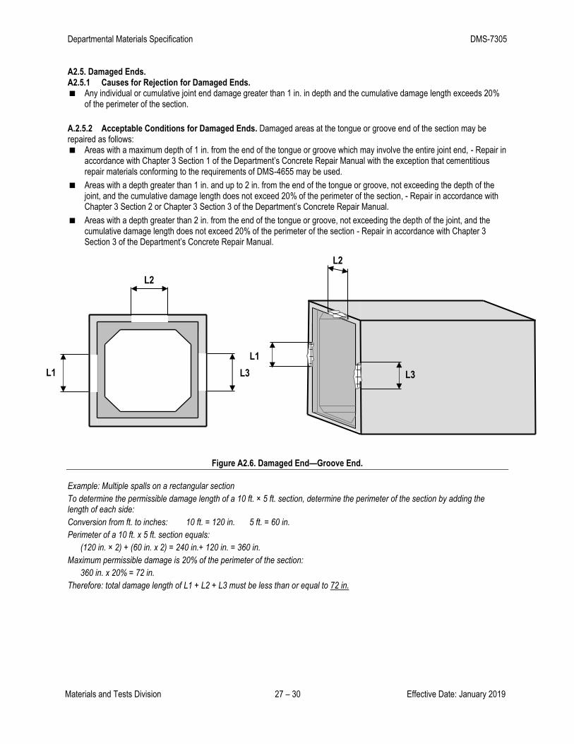
A2.5. Damaged Ends. A2.5.1 Causes for Rejection for Damaged Ends. Any individual or cumulative joint end damage greater than 1 in. in depth and the cumulative damage length exceeds 20%
of the perimeter of the section.
A.2.5.2 Acceptable Conditions for Damaged Ends. Damaged areas at the tongue or groove end of the section may be repaired as follows: Areas with a maximum depth of 1 in. from the end of the tongue or groove which may involve the entire joint end, - Repair in
accordance with Chapter 3 Section 1 of the Department’s Concrete Repair Manual with the exception that cementitious repair materials conforming to the requirements of DMS-4655 may be used.
Areas with a depth greater than 1 in. and up to 2 in. from the end of the tongue or groove, not exceeding the depth of the joint, and the cumulative damage length does not exceed 20% of the perimeter of the section, - Repair in accordance with Chapter 3 Section 2 or Chapter 3 Section 3 of the Department’s Concrete Repair Manual.
Areas with a depth greater than 2 in. from the end of the tongue or groove, not exceeding the depth of the joint, and the cumulative damage length does not exceed 20% of the perimeter of the section - Repair in accordance with Chapter 3 Section 3 of the Department’s Concrete Repair Manual.
Figure A2.6. Damaged End—Groove End.
Example: Multiple spalls on a rectangular section
To determine the permissible damage length of a 10 ft. × 5 ft. section, determine the perimeter of the section by adding the length of each side:
Conversion from ft. to inches: 10 ft. = 120 in. 5 ft. = 60 in.
Perimeter of a 10 ft. x 5 ft. section equals:
(120 in. × 2) + (60 in. x 2) = 240 in.+ 120 in. = 360 in.
Maximum permissible damage is 20% of the perimeter of the section:
360 in. x 20% = 72 in.
Therefore: total damage length of L1 + L2 + L3 must be less than or equal to 72 in.
L1
L2
L3 L1
L2
L3

Departmental Materials Specification DMS-7305
Materials and Tests Division 28 – 30 Effective Date: January 2019
A.3. SLAB SECTIONS
A3.1. Fractures or Cracks.
A3.1.1. Causes for Rejection Due to Fractures or Cracks. Any fracture or crack that passes through the slab section;
Any fracture or crack that is 0.01 in. wide or greater at the surface and 12 in. or longer and extends beyond the first layer of steel reinforcement, or
Any fractures or cracks not covered above that are numerous and extensive.
If a visible crack exists and QC is unable to observe opposite side, the producer will have the option of either eliminating the obstruction or removing the section from the lot.
Figure A.3.1. Rejectable Fractures or Cracks.
Condition #1—Crack passes through the slab, regardless of crack width or length.
Condition #2—Crack is at least 0.01 in. wide and at least 12 in. long, extends beyond the first layer of steel
reinforcement, even though it does not pass through the slab.
A3.1.2. Acceptable Conditions Due to Fractures or Cracks. Fractures or cracks not passing through the slab, provided they are:
less than 0.01 in. wide - acceptable without repair, or
0.01 in. wide or greater, regardless of length, and not extending beyond the first layer of steel reinforcement—repair with cementitious repair materials conforming to the requirements of DMS-4655.
Figure A.3.2. Acceptable Fractures or Cracks.
B
B Section B-B
Section A-A
Condition #2
0.01 in. wide or greater
12 inches long or greater
Does not pass through the wall
Extends beyond the first layer of reinforcement
Condition #1
Passes through slab

Departmental Materials Specification DMS-7305
Materials and Tests Division 29 – 30 Effective Date: January 2019
A3.2. Manufacturing Defects.
A3.2.1. Causes for Rejection Due to Manufacturing Defects. Any defect that indicates imperfect proportioning, mixing, or
molding including:
Offsets in form seams that would prevent adequate concrete cover over reinforcing steel,
Evidence of fresh concrete segregation, i.e. slick surface or sand streaking, or
Evidence of inadequate concrete cover for reinforcing steel.
A3.2.2. Causes for Rejection of Surface Defects Due to Honeycomb or Open Texture. Honeycomb or open texture extending to steel reinforcement, that exceeds 18 in. in any direction, or
Defects with a depth greater than 2 inches.
Any less severe surface condition that affects the majority of the surface and could reduce the durability and service life of the member.
Figure A.3.3. Rejectable Manufacturing Defect.
A3.2.3. Acceptable Conditions of Surface Defects Due to Honeycomb or Open Texture. Honeycomb or open texture surface conditions less severe than stated in Section A3.2.2 are acceptable if properly repaired.
Areas with a maximum depth of 1 in.- Repair in accordance with Chapter 3 Section 1 of the Department’s Concrete Repair Manual with the exception that cementitious repair materials conforming to the requirements of DMS-4655 may be used or
Areas with a depth greater than 1 in. and up to 2 in. - Repair in accordance with Chapter 3 Section 2 of the Department’s Concrete Repair Manual with the exception that batch concrete from the same mix design used in the member may be used.
A3.3. Concrete Spalls A3.3.1. Causes for Rejection Due to Spalls. More than two spalled areas in a section,
Spalls with a depth greater than 2 inches or
Any spall in the section extending to the reinforcing steel that exceeds 18 in. in any direction.
Figure A.3.4. Rejectable Spalls.
A3.3.2. Acceptable Conditions Due to Spalls. Spalled areas not greater than 18 in. in any direction and extending to the reinforcing steel may be repaired per one of the
following methods:
greater than 18 in.
greater than 18 Inches

Departmental Materials Specification DMS-7305
Materials and Tests Division 30 – 30 Effective Date: January 2019
Areas with a maximum depth of 1 in.- Repair in accordance with Chapter 3 Section 1 of the Department’s Concrete Repair Manual with the exception that cementitious repair materials conforming to the requirements of DMS-4655 may be used.
Areas with a depth greater than 1 in. and up to 2 in. - Repair in accordance with Chapter 3 Section 2 or Chapter 3 Section 3 of the Department’s Concrete Repair Manual.