fabrication, inspection, and testing of pressure vessels
DESCRIPTION
pressure vesselTRANSCRIPT
Note: The source of the technical material in this volume is the Professional Engineering Development Program (PEDP) of Engineering Services.
Warning: The material contained in this document was developed for Saudi Aramco and is intended for the exclusive use of Saudi Aramco’s employees. Any material contained in this document which is not already in the public domain may not be copied, reproduced, sold, given, or disclosed to third parties, or otherwise used in whole, or in part, without the written permission of the Vice President, Engineering Services, Saudi Aramco.
Chapter : Mechanical For additional information on this subject, contact File Reference: MEX-202.04 PEDD Coordinator on 874-6556
Engineering Encyclopedia Saudi Aramco DeskTop Standards
FABRICATION, INSPECTION, AND TESTING OF PRESSURE VESSELS
Engineering Encyclopedia Design of Pressure Vessels
Fabrication, Inspection, and Testing of Pressure Vessels
Saudi Aramco DeskTop Standards i
Content Page INTRODUCTION............................................................................................................4
EVALUATING FABRICATION DRAWINGS FOR ACCEPTABILITY..............................5
Welding Fundamentals........................................................................................6
Types of Welded Joints .....................................................................................10
Groove Welds .........................................................................................11
Fillet Welds .............................................................................................14
Plug Welds..............................................................................................15
Weld Joint Categories.............................................................................15
Welding Procedures and Welder Qualification ..................................................16
Welding Procedures................................................................................17
Welder Qualification................................................................................20
Acceptable Welding Details ...............................................................................21
Saudi Aramco Weld Detail Requirements...............................................21
ASME Weld Detail Requirements ...........................................................22
Tolerances.........................................................................................................23
Heads and Shells....................................................................................24
Plate Thickness ......................................................................................25
Alignment................................................................................................26
DETERMINING WHETHER VENDOR INSPECTION AND TESTING PLANS SATISFY SAUDI ARAMCO REQUIREMENTS...............................28
Methods of Examination ....................................................................................31
Radiographic Examination (RT) ..............................................................31
Visual Inspection (VT).............................................................................33
Liquid Penetrant Examination (PT) .........................................................33
Magnetic Particle Test (MT)....................................................................35
Engineering Encyclopedia Design of Pressure Vessels
Fabrication, Inspection, and Testing of Pressure Vessels
Saudi Aramco DeskTop Standards ii
Ultrasonic Examination (UT) ...................................................................36
Type and Extent of Required Examination ........................................................40
Pressure Test Plans ..........................................................................................41
Hardness Test Plans .........................................................................................50
Brinell Hardness Test..............................................................................51
Vickers Hardness Test............................................................................51
Hardness Test Results............................................................................51
Impact Test Plans..............................................................................................54
Applicable Codes and Standards ......................................................................56
SUMMARY...................................................................................................................57
WORK AID 1: STEPS, DRAWINGS, AND CODE (SAES-W-010) AND PROCESS REQUIREMENTS FOR EVALUATING FABRICATION DRAWINGS FOR ACCEPTABILITY ...........................58
WORK AID 2: STEPS FOR DETERMINING WHETHER VENDOR INSPECTION AND TESTING PLANS SATISFY SAUDI ARAMCO REQUIREMENTS....................................63
Work Aid 2A: Procedure for Inspection Plans...................................................63
Work Aid 2B: Procedure for Pressure Test Plans.............................................66
Work Aid 2C: Procedure for Hardness Test Plans............................................70
Work Aid 2D: Procedure for Impact Test Plans ................................................71
GLOSSARY .................................................................................................................72
Engineering Encyclopedia Design of Pressure Vessels
Fabrication, Inspection, and Testing of Pressure Vessels
Saudi Aramco DeskTop Standards iii
List of Figures
Figure 1: Typical AC Arc Welding Circuit .....................................................................7
Figure 2: Heat-Affected Zone .......................................................................................8
Figure 3: Coated Electrode Weld Deposit ....................................................................9
Figure 4: Examples of Welded Joints and Weld Types ..............................................10
Figure 5: Types of Groove Welds...............................................................................11
Figure 6: Fillet Weld at a Tee Joint.............................................................................14
Figure 7: Edge Alignment in Butt Welds.....................................................................27
Figure 8: Typical Weld Defects ..................................................................................29
Figure 9: Typical RT Setup.........................................................................................32
Figure 10: Sub-Surface Defect Along Magnetic Lines of Flux ....................................36
Figure 11: Pulse Echo UT System .............................................................................37
Figure 12: Through-Transmission UT System............................................................38
Figure 13: Summary of NDE Types............................................................................39
Figure 14: Sample Problem 1.....................................................................................46
Figure 15: Typical Shell Transitions ...........................................................................59
Figure 16: Typical Head-to-Shell Transitions .............................................................60
Figure 17: Nozzle Neck Attachment to Thinner Pipe..................................................61
Figure 18: Stiffener Ring Attachment .........................................................................61
Engineering Encyclopedia Design of Pressure Vessels
Fabrication, Inspection, and Testing of Pressure Vessels
Saudi Aramco DeskTop Standards 4
INTRODUCTION
MEX 202.02 and MEX 202.03 discussed material selection and mechanical design requirements for pressure vessels. Several items that were related to fabrication, inspection, and testing were mentioned in those modules, where necessary, without an in-depth discussion. This module discusses fabrication, inspection, and testing requirements for pressure vessels. It provides the information that is needed for Participants to evaluate fabrication drawings and testing and inspection plans that are proposed by pressure vessel manufacturers.
Engineering Encyclopedia Design of Pressure Vessels
Fabrication, Inspection, and Testing of Pressure Vessels
Saudi Aramco DeskTop Standards 5
EVALUATING FABRICATION DRAWINGS FOR ACCEPTABILITY
Welding is the most common method that is used for pressure vessel fabrication; therefore, this section focuses on welding. Welding fundamentals and details are discussed to the extent necessary for a pressure vessel engineer to achieve an adequate knowledge of welding requirements as they relate to pressure vessels. Additional welding engineering details are beyond the scope of this course.
This section also discusses dimensional tolerances which must be applied to pressure vessel components and fabrications. Adherence to relatively stringent dimensional tolerances is necessary to help achieve quality pressure vessel fabrication and acceptable long term reliability.
Saudi Aramco fabrication requirements supplement those that are contained in the ASME Code, Section VIII, Divisions 1 and 2. Saudi Aramco fabrication requirements are contained primarily in SAES-D-001, Design Criteria for Pressure Vessels; 32-SAMSS-004, Pressure Vessels; and SAES-W-010, Welding Requirements for Pressure Vessels. Relevant Saudi Aramco and ASME requirements are highlighted within the topics that are discussed in this section.
This section discusses only Division 1 requirements. Division 2 requirements are generally more stringent than those that are contained in Division 1. Participants are referred to Division 2 for additional details as required.
Engineering Encyclopedia Design of Pressure Vessels
Fabrication, Inspection, and Testing of Pressure Vessels
Saudi Aramco DeskTop Standards 6
Welding Fundamentals
A weld is defined as a localized union of metal that is achieved in plastic and molten states, with or without the addition of filler metal or the application of pressure. Welding is used in the fabrication of pressure vessels for both pressure containing parts (for example, shells and heads) and nonpressure containing parts (for example, stiffener rings, lifting lugs, and supports). Joints that are welded instead of bolted are also sometimes used for pipe-to-equipment connections in situations where the leakage potential of a bolted joint must be eliminated.
The most common welding method is called fusion welding. The fusion welding method does not require any pressure to form the weld. The seam that is to be welded is heated, usually by means of burning gas or through the use of an electric arc which is brought to fusion temperature. Additional metal, if needed, is supplied by melting a filler rod into the weld area. The filler rod is made of a material whose composition is similar to that of the pieces that are being joined. The most widely used industrial welding method is arc welding. Arc welding is the general name that is given to several welding processes that generate the heat of fusion by the use of an electric arc.
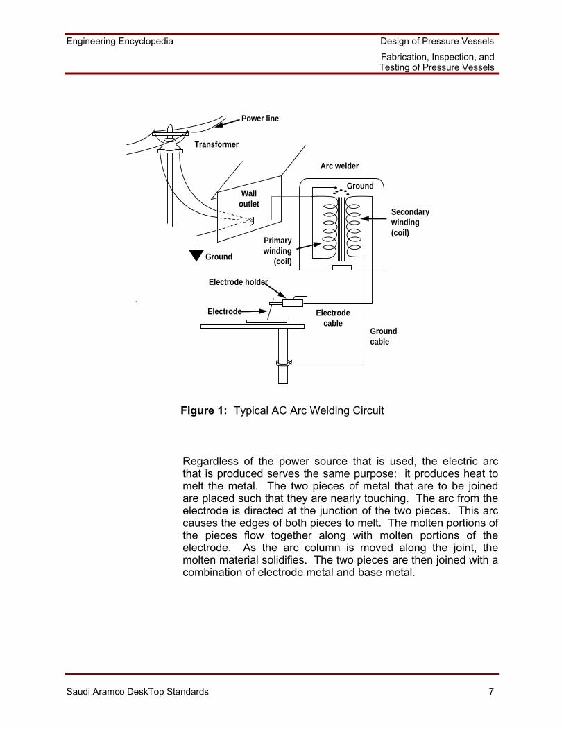
An arc welding circuit consists of the following elements:
• Power source
• Two cables (the electrode cable and the ground cable)
• Ground clamp
• Electrode holder
• Electrodes or rods
Two types of power supplies are used for arc welding: the direct current (dc) generator and the alternating current (ac) transformer. The choice of power supply depends on the particular welding that is to be done. Figure 1 shows a typical ac arc welding circuit.
Engineering Encyclopedia Design of Pressure Vessels
Fabrication, Inspection, and Testing of Pressure Vessels
Saudi Aramco DeskTop Standards 7
Power line
Transformer
Walloutlet
Arc welder
Ground
Ground
Primarywinding
(coil)
Secondarywinding(coil)
Electrodecable
Groundcable
Electrode holder
Electrode
Figure 1: Typical AC Arc Welding Circuit
Regardless of the power source that is used, the electric arc that is produced serves the same purpose: it produces heat to melt the metal. The two pieces of metal that are to be joined are placed such that they are nearly touching. The arc from the electrode is directed at the junction of the two pieces. This arc causes the edges of both pieces to melt. The molten portions of the pieces flow together along with molten portions of the electrode. As the arc column is moved along the joint, the molten material solidifies. The two pieces are then joined with a combination of electrode metal and base metal.
Engineering Encyclopedia Design of Pressure Vessels
Fabrication, Inspection, and Testing of Pressure Vessels
Saudi Aramco DeskTop Standards 8
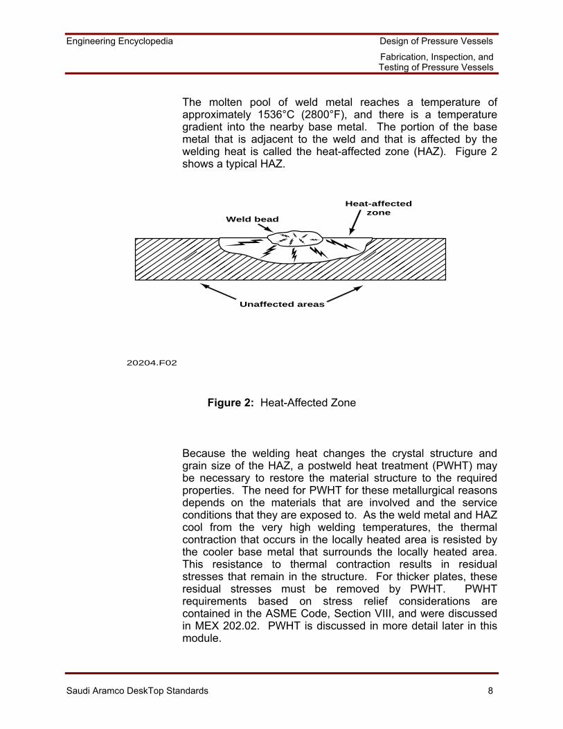
The molten pool of weld metal reaches a temperature of approximately 1536°C (2800°F), and there is a temperature gradient into the nearby base metal. The portion of the base metal that is adjacent to the weld and that is affected by the welding heat is called the heat-affected zone (HAZ). Figure 2 shows a typical HAZ.
�������������
Unaffected areas
Weld bead
Heat-affectedzone
20204.F02
Figure 2: Heat-Affected Zone
Because the welding heat changes the crystal structure and grain size of the HAZ, a postweld heat treatment (PWHT) may be necessary to restore the material structure to the required properties. The need for PWHT for these metallurgical reasons depends on the materials that are involved and the service conditions that they are exposed to. As the weld metal and HAZ cool from the very high welding temperatures, the thermal contraction that occurs in the locally heated area is resisted by the cooler base metal that surrounds the locally heated area. This resistance to thermal contraction results in residual stresses that remain in the structure. For thicker plates, these residual stresses must be removed by PWHT. PWHT requirements based on stress relief considerations are contained in the ASME Code, Section VIII, and were discussed in MEX 202.02. PWHT is discussed in more detail later in this module.
Engineering Encyclopedia Design of Pressure Vessels
Fabrication, Inspection, and Testing of Pressure Vessels
Saudi Aramco DeskTop Standards 9
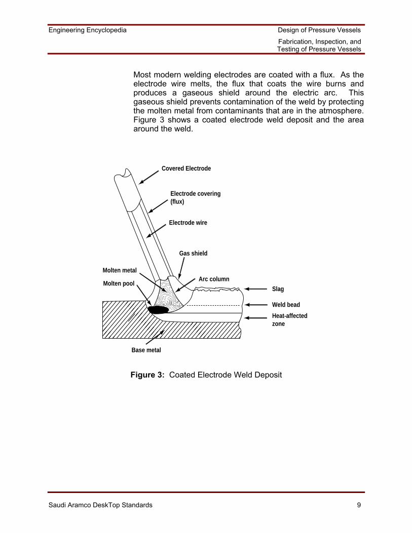
Most modern welding electrodes are coated with a flux. As the electrode wire melts, the flux that coats the wire burns and produces a gaseous shield around the electric arc. This gaseous shield prevents contamination of the weld by protecting the molten metal from contaminants that are in the atmosphere. Figure 3 shows a coated electrode weld deposit and the area around the weld.
�
���
���
���
��
Base metal
Weld bead
Heat-affectedzone��
�� Slag
Arc column
Gas shield
Molten pool
Molten metal
Electrode wire
Electrode covering(flux)
Covered Electrode
Figure 3: Coated Electrode Weld Deposit
Engineering Encyclopedia Design of Pressure Vessels
Fabrication, Inspection, and Testing of Pressure Vessels
Saudi Aramco DeskTop Standards 10
When the electrode flux melts, part of it mixes with impurities that are in the molten pool and causes these impurities to float to the top of the weld. When this mixture of impurities and flux cools, it forms a slag. The slag protects the weld bead from the atmosphere and causes the weld bead to cool more uniformly. The slag also helps to form the contour of the weld bead by acting as an insulator. The slag allows an even heat loss from the local area by insulation of the weld and HAZ. This even heat loss helps to control the grain structure of the metal. The slag is chipped away after each weld pass before slag is deposited by another weld pass; otherwise, weld defects will be caused. In order to permit later weld inspections, the slag is also chipped away when the metal has cooled after the final weld pass.
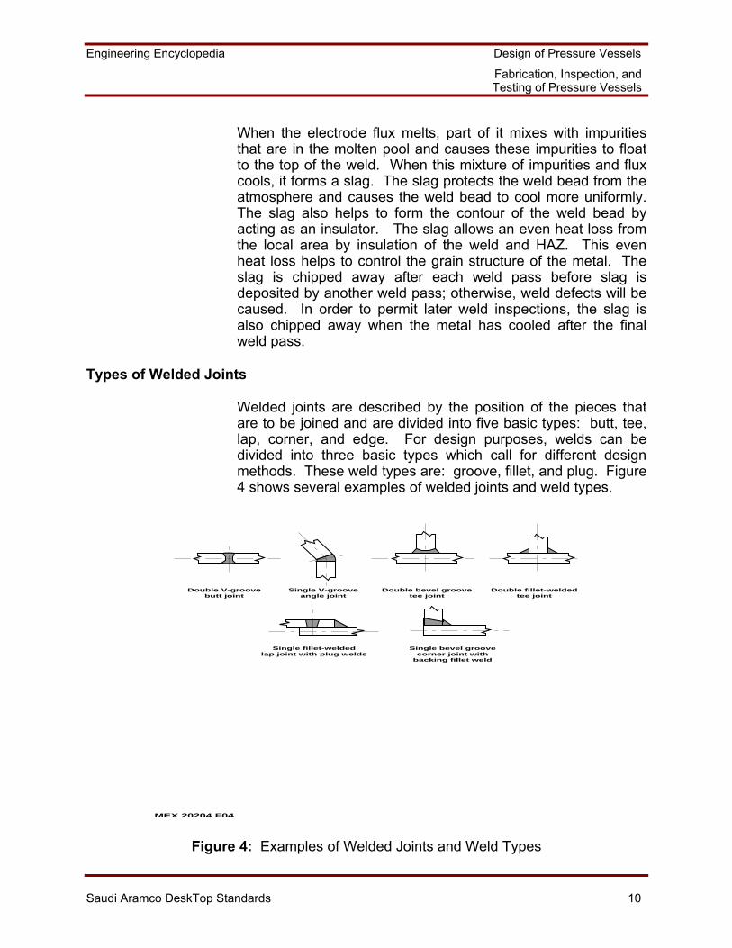
Types of Welded Joints
Welded joints are described by the position of the pieces that are to be joined and are divided into five basic types: butt, tee, lap, corner, and edge. For design purposes, welds can be divided into three basic types which call for different design methods. These weld types are: groove, fillet, and plug. Figure 4 shows several examples of welded joints and weld types.
Double V-groovebutt joint
Single V-grooveangle joint
Double bevel groovetee joint
Double fillet-weldedtee joint
Single fillet-weldedlap joint with plug welds
Single bevel groovecorner joint with
backing fillet weld
MEX 20204.F04
Figure 4: Examples of Welded Joints and Weld Types
Engineering Encyclopedia Design of Pressure Vessels
Fabrication, Inspection, and Testing of Pressure Vessels
Saudi Aramco DeskTop Standards 11
Note that, in some cases, a given joint type may employ only one weld type, such as the groove weld that is used in the butt joint. Other joint types may employ two weld types, such as the groove and fillet welds that are used in the corner joint.
The choice of the joint and weld type that is to be used in each case depends on the following:
• Saudi Aramco and ASME Code requirements. • The geometric relationship between the parts that are
being joined and the access that is available for welding. • Economic considerations.
Groove Welds
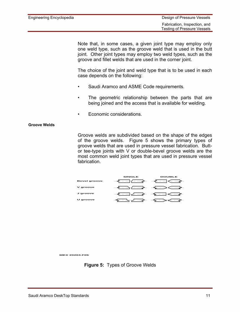
Groove welds are subdivided based on the shape of the edges of the groove welds. Figure 5 shows the primary types of groove welds that are used in pressure vessel fabrication. Butt- or tee-type joints with V or double-bevel groove welds are the most common weld joint types that are used in pressure vessel fabrication.
MEX 20204.F05
SINGLE DOUBLE
Bevel groove
V groove
J groove
U groove
Figure 5: Types of Groove Welds
Engineering Encyclopedia Design of Pressure Vessels
Fabrication, Inspection, and Testing of Pressure Vessels
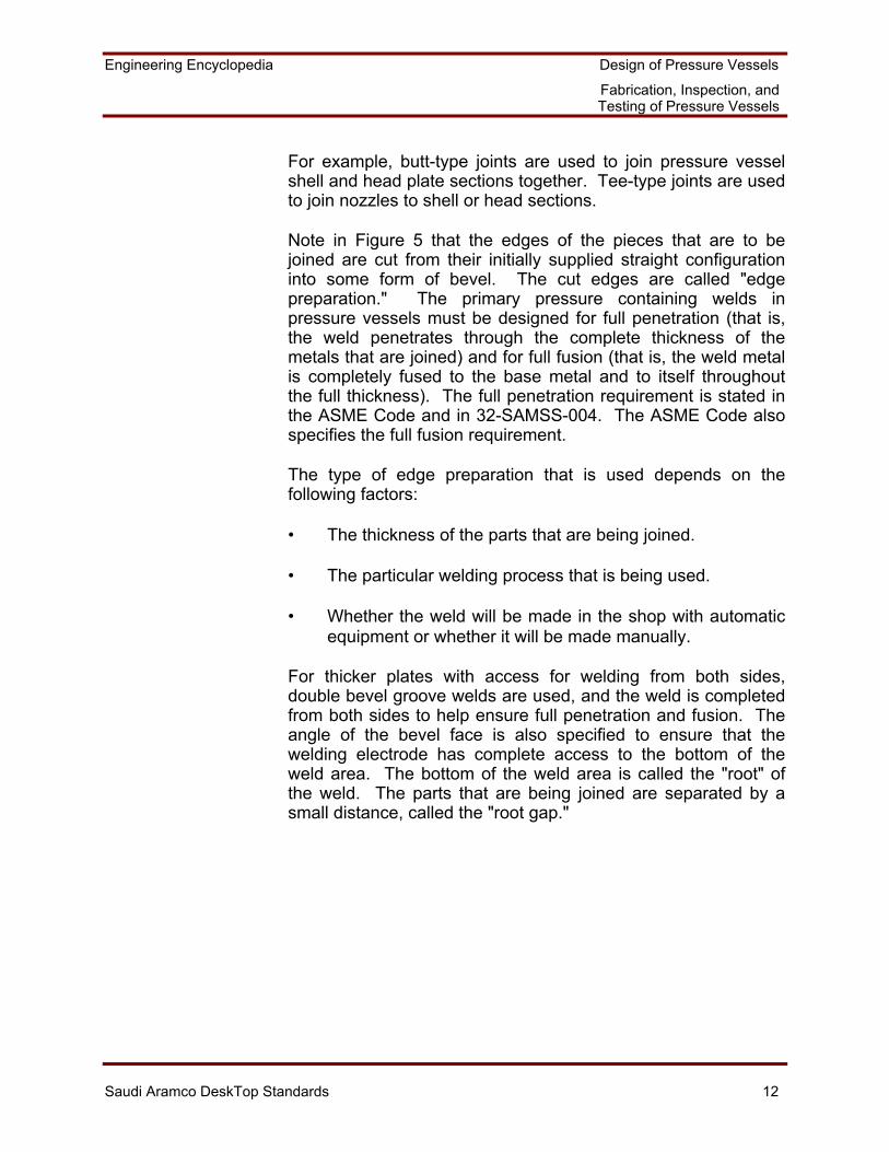
Saudi Aramco DeskTop Standards 12
For example, butt-type joints are used to join pressure vessel shell and head plate sections together. Tee-type joints are used to join nozzles to shell or head sections.
Note in Figure 5 that the edges of the pieces that are to be joined are cut from their initially supplied straight configuration into some form of bevel. The cut edges are called "edge preparation." The primary pressure containing welds in pressure vessels must be designed for full penetration (that is, the weld penetrates through the complete thickness of the metals that are joined) and for full fusion (that is, the weld metal is completely fused to the base metal and to itself throughout the full thickness). The full penetration requirement is stated in the ASME Code and in 32-SAMSS-004. The ASME Code also specifies the full fusion requirement.
The type of edge preparation that is used depends on the following factors:
• The thickness of the parts that are being joined. • The particular welding process that is being used. • Whether the weld will be made in the shop with automatic
equipment or whether it will be made manually. For thicker plates with access for welding from both sides, double bevel groove welds are used, and the weld is completed from both sides to help ensure full penetration and fusion. The angle of the bevel face is also specified to ensure that the welding electrode has complete access to the bottom of the weld area. The bottom of the weld area is called the "root" of the weld. The parts that are being joined are separated by a small distance, called the "root gap."
Engineering Encyclopedia Design of Pressure Vessels
Fabrication, Inspection, and Testing of Pressure Vessels
Saudi Aramco DeskTop Standards 13
As the thickness of the parts that are to be joined increases, the width of the open area at the surface of the weld for a V-groove weld preparation increases because the bevel angle is constant through the entire thickness. This extra width requires a larger amount of weld metal to make the closure. This extra weld metal increases the cost of fabrication for both material and labor. The J or U groove-type weld preparations are more frequently used in thick fabrications. With these J- or U-groove weld geometries, the weld root is completely accessible, but the total amount of open area that is to be filled with weld metal is reduced in comparison to the V-groove preparation. The weld preparation cost is more for a J- or U-groove weld. However, when thick components are being joined, the total weld cost is less for a J- or U-groove due to the reduced actual welding time and material.
The strength of a groove weld is based on the following:
• Cross-sectional area that is subject to shear, tension, or compression.
• Allowable stress of the weld metal (which is nearly always
the same as that of the parts that are to be joined).
Stresses in groove welds are computed through the use of standard formulas for tension, bending, and shear. The full penetration groove weld is the most reliable of all weld types. There are no significant stress concentration effects in a full penetration groove weld because there are no abrupt geometric discontinuities. The joint efficiency is specified by the ASME Code and depends on the type of weld examination that is used, as was discussed in MEX 202.03.
Engineering Encyclopedia Design of Pressure Vessels
Fabrication, Inspection, and Testing of Pressure Vessels
Saudi Aramco DeskTop Standards 14
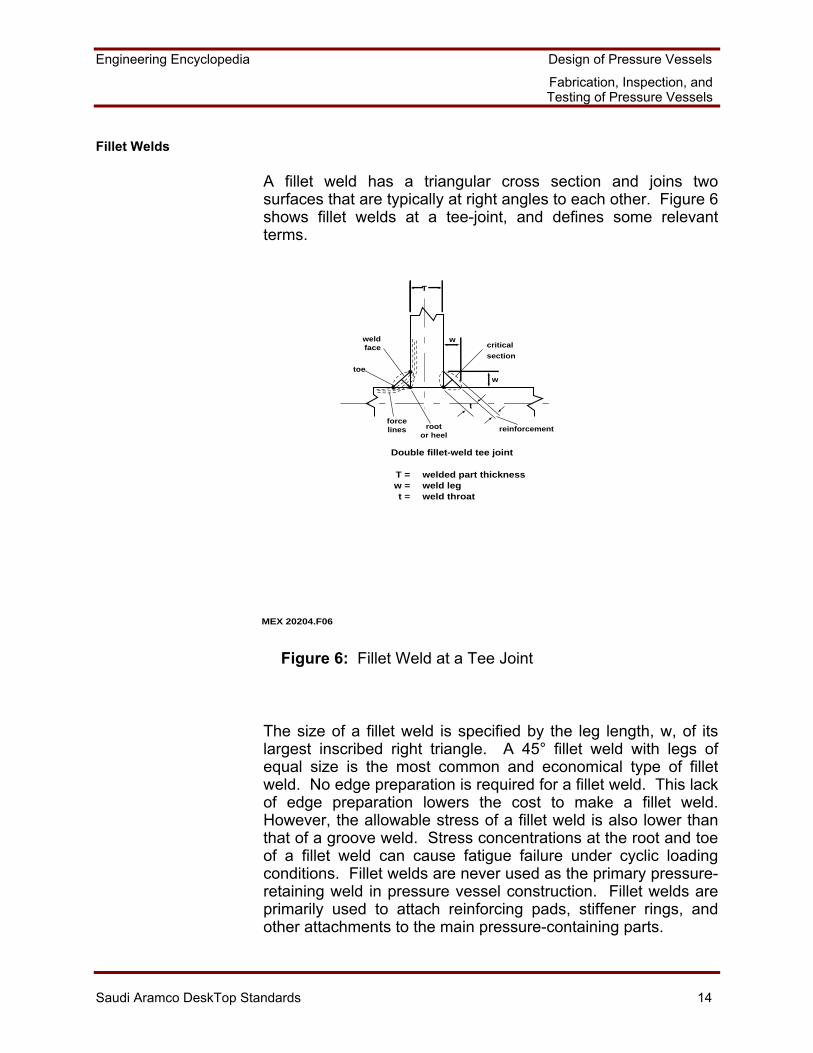
Fillet Welds
A fillet weld has a triangular cross section and joins two surfaces that are typically at right angles to each other. Figure 6 shows fillet welds at a tee-joint, and defines some relevant terms.
MEX 20204.F06
T
w
w
critical
section
weldface
toe
forcelines root
or heel
t
reinforcement
T =w =t =
welded part thicknessweld legweld throat
Double fillet-weld tee joint
Figure 6: Fillet Weld at a Tee Joint
The size of a fillet weld is specified by the leg length, w, of its largest inscribed right triangle. A 45° fillet weld with legs of equal size is the most common and economical type of fillet weld. No edge preparation is required for a fillet weld. This lack of edge preparation lowers the cost to make a fillet weld. However, the allowable stress of a fillet weld is also lower than that of a groove weld. Stress concentrations at the root and toe of a fillet weld can cause fatigue failure under cyclic loading conditions. Fillet welds are never used as the primary pressure-retaining weld in pressure vessel construction. Fillet welds are primarily used to attach reinforcing pads, stiffener rings, and other attachments to the main pressure-containing parts.
Engineering Encyclopedia Design of Pressure Vessels
Fabrication, Inspection, and Testing of Pressure Vessels
Saudi Aramco DeskTop Standards 15
The stresses in fillet welds are complex because of the eccentricity of the applied load, the weld shape, and stress concentration effects. These stresses consist of shear, tension, and compression stresses. The stress distribution is not uniform across the throat and leg of a fillet weld and varies along the length of the fillet weld. However, practical assumptions are made with regard to the fillet weld geometry and applied load in order to simplify design.
Where fillet welds are used for attachments to a pressure vessel, SAES-D-001 requires that the weld be continuous. A continuous fillet weld is required to prevent the occurrence of corrosion between the attachment and the vessel due to corrosive fluid being trapped between the two parts.
Plug Welds
A plug weld is a circular weld that is made through one member of a lap or tee-type joint. Plug weld holes in thin plates are completely filled with weld metal through the entire plate thickness. Plug weld holes are typically only partially filled in plates that are about 9.5 mm (3/8 in.) thick and over. Plug welds are most often used in pressure vessel construction to fix a corrosion-resistant strip lining into an existing vessel.
Weld Joint Categories
The ASME Code, Section VIII, Division 1, defines weld joint "categories" by the location of a joint in a vessel. The joints that are included in each category are designated as Categories A, B, C, or D. The Categories are used by the ASME Code in the specification of joint type and degree of inspection for certain welded pressure-containing joints. Recall that these categories were used in MEX 202.03 in the discussion of weld joint efficiency.
Engineering Encyclopedia Design of Pressure Vessels
Fabrication, Inspection, and Testing of Pressure Vessels
Saudi Aramco DeskTop Standards 16
As previously discussed, the ASME Code specifies, in Table UW-12, the weld joint types that may be used in each Category. The following are examples of specifications in Table UW-12:
• Buttwelded joints that are made by double-welding (i.e., welded from both sides) or by other means which will obtain the same weld metal quality on the inside and outside weld surfaces may be used for all joint categories. This is the most commonly used weld type for the weld seams of the main pressure vessel because it results in the best weld joint efficiencies. If a metal backing strip is used for this weld, the metal backing strip cannot remain in place.
• A single-welded butt joint with a backing strip also could be
used for all joint categories in the ASME Code, but such a joint achieves lower joint efficiencies. However, 32-SAMSS-004 and SAES-W-010 prohibit the use of permanent backing strips.
• The ASME Code permits the use of a single-welded butt
joint without a backing strip for Categories A, B, and C; but the code allows such a joint only for circumferential butt joints that are not over 16 mm (0.625 in.) thick and that are not over 610 mm (24 in.) in outside diameter. From a practical standpoint, the allowable weld joint efficiency is so low for this type of joint that it is typically not used for pressure vessels in refinery applications.
Economics is a consideration in the determination of what weld joint efficiency and weld type to use. Higher weld joint efficiencies reduce the required component thicknesses, which reduce material and fabrication costs. However, these cost reductions come at the expense of more expensive weld joint preparations and inspection.
Welding Procedures and Welder Qualification
The achievement of high quality pressure vessel fabrication requires the use of tested welding procedures as well as qualified welders or welding machines. The ASME Code, Section VIII contains rules for the mechanical design, fabrication, and testing of pressure vessels. The ASME Code, Section IX covers welding procedures and welder qualifications, and the use of Section IX is specified in SAES-W-010. Section IX is not covered in this section. However, several welding procedure and welder qualification requirements are highlighted in the following paragraphs.
Engineering Encyclopedia Design of Pressure Vessels
Fabrication, Inspection, and Testing of Pressure Vessels
Saudi Aramco DeskTop Standards 17
Welding Procedures
The pressure vessel designer determines the basic type and size of weld and the weld joint configuration to use in vessel fabrication. The welding engineer, on the other hand, must specify exactly how the vessel components are to be welded together, based on the following parameters:
• Material of components
• Thickness of components to be joined
• Diameter of components to be joined
• Position and direction of welding
• Type of weld bevel to use (e.g., V, U, J, one side, both sides)
• Welding process (including variables such as the welding speed, shielding gas, and flux)
• Electrode
• DC or AC electric current
• Voltage and current levels
• Manual or automatic welding
• Preheat temperature and, possibly, PWHT procedures
The welding engineer produces a welding procedure that details exactly how the weld is to be done and considers the parameters that are listed above. Each weld joint type in a pressure vessel has its own welding procedure. When a welding procedure is developed, a welder uses the procedure to weld a sample piece, and the sample weld is inspected and tested. When the sample weld is approved, the procedure is said to be "qualified": that is, the welding procedure has been shown to produce sound welds for the intended application. Pressure vessel fabricators have well established welding procedures that are available for the types of welds and materials that they normally use. Therefore, welding procedures do not have to be qualified for every new pressure vessel that is fabricated. Additional welding procedures are qualified only for new welds that the vessel fabricator has not made before.
Engineering Encyclopedia Design of Pressure Vessels
Fabrication, Inspection, and Testing of Pressure Vessels
Saudi Aramco DeskTop Standards 18
Saudi Aramco welding procedure requirements are contained in SAES-W-001, Basic Welding Requirements. Several of these SAES-W-001 requirements that go beyond the ASME Code are highlighted as follows:
• Welding procedures must be submitted to Saudi Aramco for review and approval prior to the start of work. This review and approval procedure avoids the potential problem caused by welds being made by means of unacceptable procedures and by the need to then determine whether these welds can be accepted or whether they must be remade.
• A weld map, drawing, or table that specifies exactly where
each weld procedure will be applied must be provided by the vessel manufacturer. This information simplifies the review process, helps ensure consistency between procedure and weld, and assists maintenance personnel should repairs or alterations be required later.
• Additional requirements are also specified for the test
coupon, procedure requalification requirements, procedure variables, documentation, and approval requirements.
Preheat and PWHT requirements were discussed in MEX 202.02 and must be specified in the welding procedure. Saudi Aramco preheat and PWHT requirements are specified in SAES-W-010 and are contained in Work Aid 1.
The ASME Code contains the temperature and hold time requirements when PWHT is needed for stress relief considerations. These ASME Code PWHT requirements are based on material type and thickness, as specified in Paragraph UCS-56 for carbon and low-alloy steels. The following parameters (based on the ASME Code, Section VIII, Division 1) must be controlled during PWHT:
• The minimum PWHT temperature and the minimum holding time at temperature are specified based on the material P-No. and thickness. Acceptable PWHT procedures are also specified. These requirements ensure that adequate stress relief will occur.
Engineering Encyclopedia Design of Pressure Vessels
Fabrication, Inspection, and Testing of Pressure Vessels
Saudi Aramco DeskTop Standards 19
• Heatup and cooldown rates must be controlled within specified limits in order to avoid excessive local thermal stresses within the vessel during PWHT. For carbon and low-alloy steels, these heatup and cooldown rates are as follows: - The furnace temperature must not exceed 427°C
(800°F) before the vessel or vessel part is placed in it. - Above 427°C (800°F), the heatup rate must not be
more than 222°C (400°F)/hr divided by the maximum metal thickness of the shell or head plate, in inches. In no case can the heatup rate exceed 222°C (400°F)/hr.
- During heatup, the maximum temperature variation in
the portion of the vessel that is being heated must be limited to 139°C (250°F) in any 4.6 m (15 ft.) length.
- During the temperature hold period, the maximum
difference in temperature between any two parts of the vessel that is being heated must not exceed 83°C (150°F).
- The furnace atmosphere must be controlled to avoid
any excessive surface oxidation of the vessel. - Above 427°C (800°F), cooldown must be done in a
closed furnace or cooling chamber at a maximum rate of 278°C (500°F)/hr divided by the maximum metal thickness of the shell or head plate in inches. In no case can the cooldown rate exceed 278°C (500°F)/hr. From 427°C (800°F) down, the vessel may be cooled in still air.
Engineering Encyclopedia Design of Pressure Vessels
Fabrication, Inspection, and Testing of Pressure Vessels
Saudi Aramco DeskTop Standards 20
- Except as permitted for P-No. 1, Groups 1 through 3, and P-No. 3, Groups 1 through 3 materials, vessels which have received PWHT must receive an additional PWHT after any weld repairs have been made. The concern here is that the repair welding may defeat the benefits of the original PWHT. Weld repairs may be made to these materials after the final PWHT without doing another PWHT provided that the following conditions are met:
+ The repairs are made before the vessel
hydrotest. + The PWHT is not required for service reasons. + The size of repair is within specified limits. + Specified inspections are made.
It should be noted, however, that SAES-W-010 requires that PWHT be done after all repairs are completed. As noted earlier, the ASME Code specifies PWHT based primarily on stress relief considerations. PWHT may be required based on process service considerations as well, since welded components are prone to cracking in certain process environments. SAES-W-010 requires that PWHT be done on vessels in specific process services. These PWHT requirements are summarized in Work Aid 1.
Welder Qualification
A qualified weld procedure specifies how the weld is to be made. However, the actual welds will be made either by men or machines. An unqualified welder or defective machine results in a poor quality weld, even if a qualified welding procedure is used. Therefore, the individuals or equipment that actually do the welding must be tested to confirm that they have the capability to carry out the procedure. The result of these qualifications and tests is that qualified welding procedures are performed by qualified welders.
Engineering Encyclopedia Design of Pressure Vessels
Fabrication, Inspection, and Testing of Pressure Vessels
Saudi Aramco DeskTop Standards 21
The ASME Code requires that welders and welding operators that are used to weld pressure-containing parts and to join load-carrying nonpressure parts to pressure parts be qualified in accordance with Section IX of the ASME Code. Other requirements apply for less critical welds. Methods must also be established that relate the specific welder to his work and that permit test records to be maintained.
Acceptable Welding Details
All pressure vessel welds, including the welds that attach heads, nozzles, small fittings, and nonpressure components to a shell, must conform to requirements that are specified in the SAESs, 32-SAMSS-004, and the ASME Code. Details that are used for the primary circumferential and longitudinal welds were discussed earlier in conjunction with weld joint categories. Other Saudi Aramco and ASME Code weld detail requirements are highlighted below.
Saudi Aramco Weld Detail Requirements
Saudi Aramco specifies weld detail requirements in 32-SAMSS-004 and SAES-W-010. These requirements are contained in Work Aid 1. The paragraphs that follow elaborate on two of these requirements.
• For welded connections, a 6 mm (1/4 in.) NPS weep hole is required in each nozzle reinforcing pad, saddle wear plate, or attachment pad that covers a weld seam. The weep hole permits later pressure testing of the pad attachment welds and also provides a vent during welding.
• Support skirts are to be welded to vessel heads (with the
exception of hemispherical heads) so that the centerlines of the skirt plate and the straight flange of the head line up. This alignment eliminates any additional local stresses that may be caused by eccentric application of the vessel weight loads. The weld that attaches the skirt is to have no undercut. This lack of undercut minimizes local stress intensification effects and the potential for fatigue failure under cyclic loading.
Engineering Encyclopedia Design of Pressure Vessels
Fabrication, Inspection, and Testing of Pressure Vessels
Saudi Aramco DeskTop Standards 22
ASME Weld Detail Requirements
Work Aid 1 summarizes two locations of ASME Code weld detail requirements. The paragraphs that follow provide additional comments about several of the ASME requirements. Further information related to these and other weld details is contained in the ASME Code.
Thickness of a pressure vessel head sometimes differs from the thickness of the shell it is attached to, such as when a hemispherical head is attached to a cylindrical shell. The transition between the component thicknesses must be made gradually in a taper in order to avoid an excessive local stress. The head-to-shell weld will typically be made in the cylindrical shell. However, the weld can also be located within the taper. Head-to-shell thickness transitions are illustrated in Figure 16 in Work Aid 1.
An intermediate head is attached to the inside of a cylindrical shell when the intermediate head separates two sections of the vessel. The butt weld between shell sections also attaches to the head, and a fillet weld is also located between the head and shell. The ASME Code permits elimination of the fillet weld if there is no access and if the service is noncorrosive. However, the fillet weld should generally be used for all refinery applications to avoid the potential for accelerated corrosion due to process fluid getting between the head and shell. The attachment of an intermediate head to a cylindrical shell is illustrated in Figure 16 in Work Aid 1.
In some cases, a nozzle neck that has a weld-end may be attached to a pipe that is thinner. This attachment between components of different thicknesses could occur if extra thickness was included in the nozzle neck for reinforcement or if the pipe and nozzle materials and/or allowable stresses differ. In such a case, the nozzle neck must be tapered to the pipe thickness. Tapers of similar thickness are also used to join shell sections that are of different thicknesses. Shell thickness and nozzle thickness tapers are illustrated in Figures 15 and 17 respectively in Work Aid 1.
Engineering Encyclopedia Design of Pressure Vessels
Fabrication, Inspection, and Testing of Pressure Vessels
Saudi Aramco DeskTop Standards 23
Stiffener rings may be attached to the vessel shell by continuous, intermittent, or a combination of continuous and intermittent welds. Intermittent welds must be placed on both sides of the stiffener and may be either staggered or in-line. The ASME Code specifies acceptable spacing, size, and length of the welds. Stiffener ring attachment weld options are illustrated in Figure 18 in Work Aid 1.
Tolerances
Pressure vessel components are designed for specified dimensions through the use of procedures and equations that were discussed in MEX 202.03. The actual fabrication of the individual components and the completed vessel must match the dimensions that were used in the design calculations within relatively small tolerances. These small tolerances are required for the design to be valid and for it to have the reliability that the ASME Code intends.
The ASME Code specifies acceptable dimensional tolerances for specific situations. This specification also includes allowable alignment tolerances between components that are being welded together. Excessive misalignment between welded components can result in poor quality welds, local stress intensification effects that were not considered in the design, and a reduction in long-term weld reliability. Saudi Aramco generally accepts the ASME Code tolerance requirements without additions.
Engineering Encyclopedia Design of Pressure Vessels
Fabrication, Inspection, and Testing of Pressure Vessels
Saudi Aramco DeskTop Standards 24
Heads and Shells
The following list summarizes the primary dimensional tolerance requirements for heads and shells based on the ASME Code, Section VIII, Division 1.
• Cylindrical, conical, and spherical shells that are under internal pressure must be substantially round and must meet the following requirements:
- The difference between the maximum and minimum
inside diameters at any cross section is not to exceed 1% of the nominal diameter at the cross section. Since all the design equations are based on circular cross sections, deviations beyond this value would introduce higher local stresses that were not accounted for in the design calculations.
- When the cross section either passes through an
opening, or within a distance of one inside diameter (I.D.) from the opening measured from its center, the permissible diametral difference stated above may be increased by 2% of the opening I.D.
• Cylindrical, conical, and spherical shells that are under
external pressure must meet the same dimensional tolerances noted above, plus additional dimensional tolerances that are specified in Paragraph UG-80 of the ASME Code. These additional requirements account for local geometric discontinuities, which reduce the buckling resistance of a shell. Participants are referred to the ASME Code for details.
• The inner surface of a torispherical, toriconical,
hemispherical, or ellipsoidal head cannot deviate outside of the specified shape by more than 1-1/4% of D and cannot deviate inside the specified shape by more than 5/8% of D. D is the nominal outside diameter of the vessel shell at the point of attachment. The knuckle radius cannot be less than the specified value.
Engineering Encyclopedia Design of Pressure Vessels
Fabrication, Inspection, and Testing of Pressure Vessels
Saudi Aramco DeskTop Standards 25
• A hemispherical head or any spherical portion of a torispherical or ellipsoidal head that is designed for external pressure must meet additional tolerances that are specified in Paragraph UG-81 of the ASME Code. This requirement is due to the influence that geometric shape has on the buckling characteristics of a shell.
• The difference between the maximum and minimum
diameters of head skirts is to be limited to a maximum of 1% of the nominal diameter.
Plate Thickness
For plate material that is ordered, it must be specified that the material is to be no thinner than the required design thickness. If plate is furnished with an undertolerance of no more than the smaller of 0.25 mm (0.01 in.) or 6% of the ordered thickness, it may still be used at the full design pressure for the thickness ordered.
In the extreme case, this degree of permissible plate thickness undertolerance permits at most a 6% overstress in the vessel component. This amount of overstress will still be well below a level that could cause a failure. From a practical standpoint, there will be slight variations in plate thickness so that the entire plate would not be this thin. In addition, the allowable stresses are based on minimum permissible material strength properties, and the material will typically be stronger than these minimum permissible material strength properties. Therefore, permitting a nominal plate thickness undertolerance of up to 6% is well within reasonable safety margins.
It should also be noted that, except for certain special provisions that are noted in Paragraph UG-16, the ASME Code requires that the minimum thickness for shells and heads, after they are formed, shall be 1.6 mm (1/16 in.) exclusive of any corrosion allowance. This minimum thickness requirement results in a basic degree of mechanical integrity of the vessel regardless of the actual design loads.
Engineering Encyclopedia Design of Pressure Vessels
Fabrication, Inspection, and Testing of Pressure Vessels
Saudi Aramco DeskTop Standards 26
Alignment
As noted earlier, the alignment between two parts that are being welded together must be within a reasonable tolerance in order to achieve an acceptable weld. The list that follows highlights several ASME Code requirements for alignment.
• Plates that are to be welded together must be fitted, aligned, and retained in position during the welding operation. This procedure keeps the parts from moving during welding.
• Any tack welds that are used to achieve alignment must
either be removed when they are no longer needed, or their ends must be ground and the tack weld incorporated into the final weld. Tack welds must also be made using qualified welding procedures. If qualified welding procedures are not used, a relatively poor quality tack weld could be the initiation point of a weld failure.
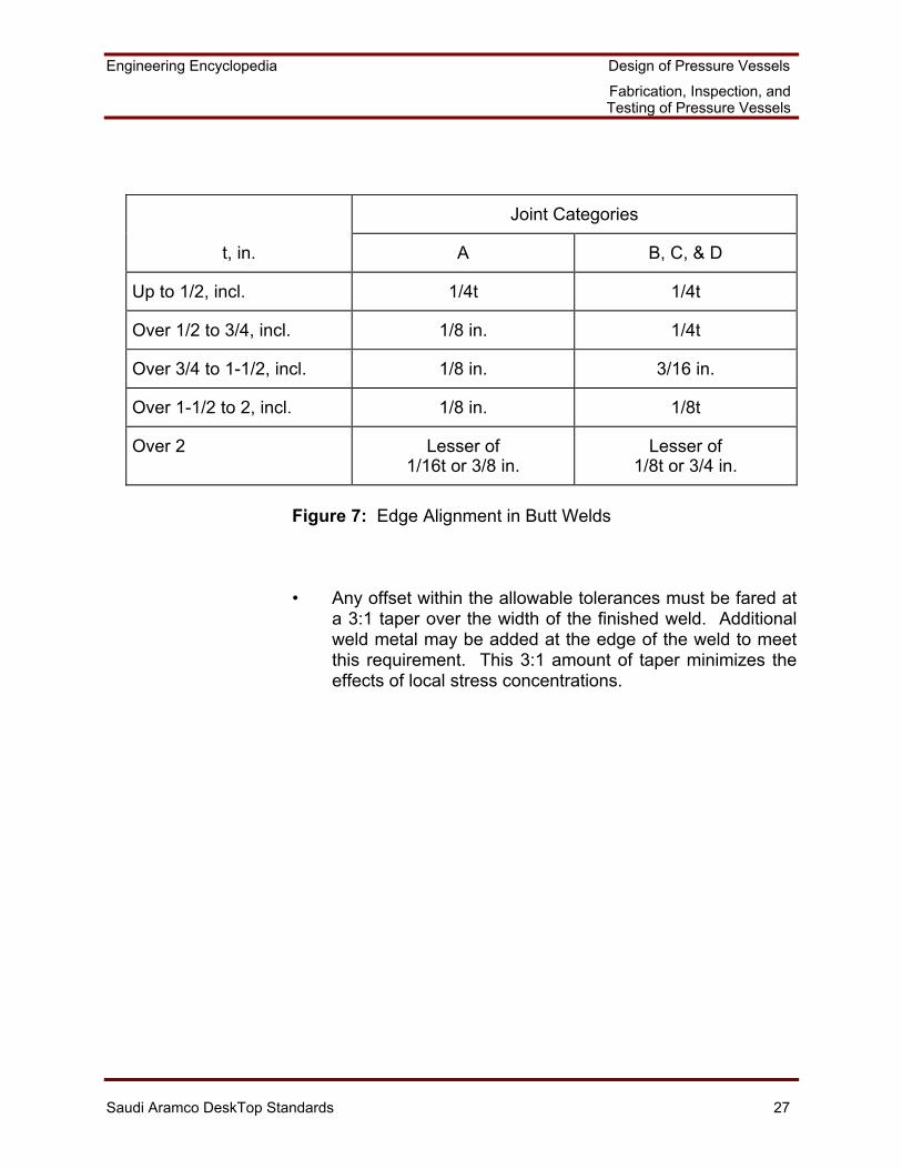
• Alignment at edges that are to be buttwelded must have a
maximum offset within the limits that are shown in Figure 7, based on weld joint category. The thickness, t, is the nominal thickness of the thinner edge at the joint.
Engineering Encyclopedia Design of Pressure Vessels
Fabrication, Inspection, and Testing of Pressure Vessels
Saudi Aramco DeskTop Standards 27
Joint Categories
t, in. A B, C, & D
Up to 1/2, incl. 1/4t 1/4t
Over 1/2 to 3/4, incl. 1/8 in. 1/4t
Over 3/4 to 1-1/2, incl. 1/8 in. 3/16 in.
Over 1-1/2 to 2, incl. 1/8 in. 1/8t
Over 2 Lesser of 1/16t or 3/8 in.
Lesser of 1/8t or 3/4 in.
Figure 7: Edge Alignment in Butt Welds
• Any offset within the allowable tolerances must be fared at a 3:1 taper over the width of the finished weld. Additional weld metal may be added at the edge of the weld to meet this requirement. This 3:1 amount of taper minimizes the effects of local stress concentrations.
Engineering Encyclopedia Design of Pressure Vessels
Fabrication, Inspection, and Testing of Pressure Vessels
Saudi Aramco DeskTop Standards 28
DETERMINING WHETHER VENDOR INSPECTION AND TESTING PLANS SATISFY SAUDI ARAMCO REQUIREMENTS
Overall inspection of completed pressure vessels includes an examination of the following:
• Welds
• Base material specification and quality
• Dimensional requirements
• Equipment documentation
This section discusses only the methods and extent of required weld examinations.
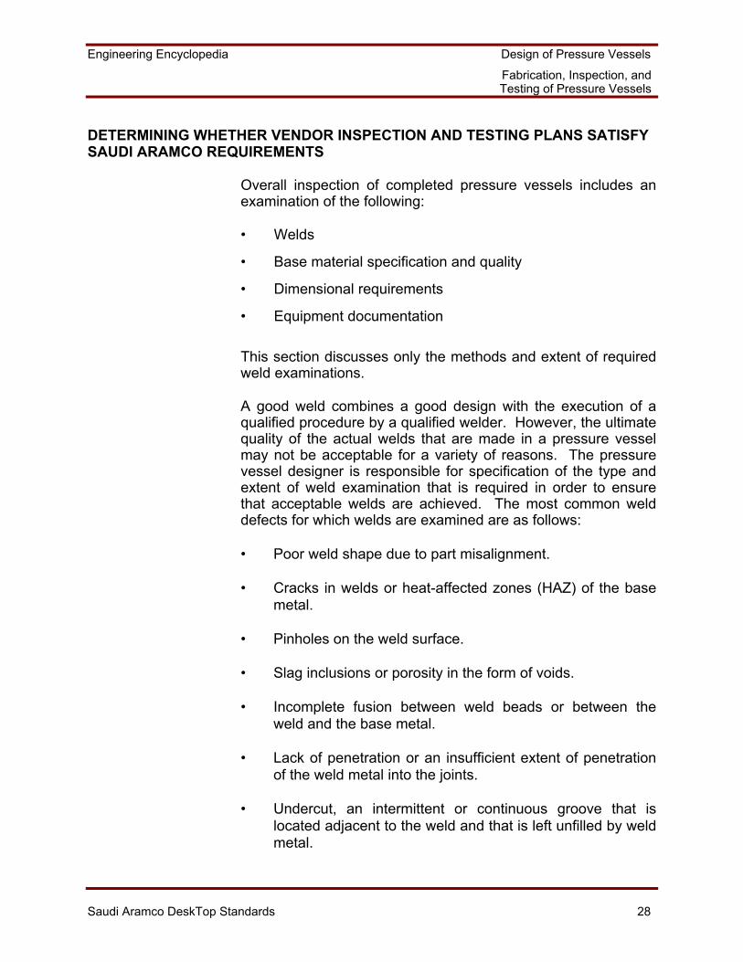
A good weld combines a good design with the execution of a qualified procedure by a qualified welder. However, the ultimate quality of the actual welds that are made in a pressure vessel may not be acceptable for a variety of reasons. The pressure vessel designer is responsible for specification of the type and extent of weld examination that is required in order to ensure that acceptable welds are achieved. The most common weld defects for which welds are examined are as follows:
• Poor weld shape due to part misalignment. • Cracks in welds or heat-affected zones (HAZ) of the base
metal. • Pinholes on the weld surface. • Slag inclusions or porosity in the form of voids. • Incomplete fusion between weld beads or between the
weld and the base metal. • Lack of penetration or an insufficient extent of penetration
of the weld metal into the joints. • Undercut, an intermittent or continuous groove that is
located adjacent to the weld and that is left unfilled by weld metal.
Engineering Encyclopedia Design of Pressure Vessels
Fabrication, Inspection, and Testing of Pressure Vessels
Saudi Aramco DeskTop Standards 29
Several of these common weld defects are illustrated in Figure 8.
���
���
��
���
���
��
���
���
�����
���
��
Lack of Fusion
Between Weld Bead and Base Metal Between Adjacent Passes
Incomplete Filling at RootIncomplete Filling at Root on One Side Only
Incomplete Penetration
���
���
��
External Undercut
Internal Undercut
Undercut
Figure 8: Typical Weld Defects
Engineering Encyclopedia Design of Pressure Vessels
Fabrication, Inspection, and Testing of Pressure Vessels
Saudi Aramco DeskTop Standards 30
The presence of defects reduces the strength of the weld below the requirements of the design calculations, reduces the overall strength of the fabrication, and increases the risk of failure. Weld inspection must be performed in a manner that will detect unacceptable defects and that will not damage the vessel material. This type of inspection is called nondestructive examination, or NDE.
Radiographic weld examination, weld joint efficiency, and ASME Code requirements have already been discussed. For example, a spot radiographic examination produces a weld joint efficiency of 0.85 in a full-penetration butt weld. A 100% radiographic examination produces a weld joint efficiency of 1.0 in a full-penetration butt weld. In practical terms, a weld joint efficiency of 1.0 means that there is greater assurance that high weld quality is achieved, that there is no difference in quality between the weld and the base metal, and that the vessel parts may, therefore, be fabricated from thinner material. Main seam pressure-containing welds are not the only ones whose quality must be assured. Welds that connect nozzles or major structural components to vessel shells must also be of high quality. The sections that follow discuss radiographic and other forms of weld inspection, the types of defects that they can detect, and the extent of required examination.
After a pressure vessel has been completely fabricated, it must be pressure-tested before it is considered safe for operation. The objective of a pressure test is to bring the vessel, under controlled conditions, to an internal pressure that is high enough to demonstrate its mechanical integrity. Later sections discuss pressure test requirements in more detail.
Weld hardness tests may be required prior to fabrication and after the welding of vessel components, based on service considerations and the vessel material. Weld hardness must be kept below specified maximum values in order to decrease the potential for weld cracking in certain process environments.
If the material is not exempt from impact testing in accordance with Division 2 requirements, Charpy impact tests must be made to confirm that the material has adequate fracture toughness prior to fabrication. The need for this impact testing must be included as part of the vessel vendor's fabrication plans.
Engineering Encyclopedia Design of Pressure Vessels
Fabrication, Inspection, and Testing of Pressure Vessels
Saudi Aramco DeskTop Standards 31
Methods of Examination
The five primary weld NDE methods are as follows:
• Radiographic examination (RT)
• Visual Inspection (VT)
• Liquid penetrant examination (PT)
• Magnetic particle test (MT)
• Ultrasonic examination (UT)
The choice of which weld examination method or methods to use depends on the weld quality required of the joint, the position of the weld, the material to be joined, and the particular defects that are expected. These weld NDE methods are discussed in the paragraphs that follow.
Radiographic Examination (RT)
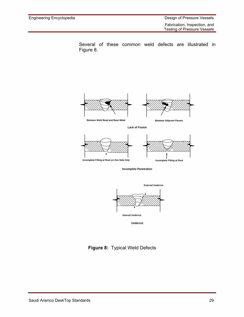
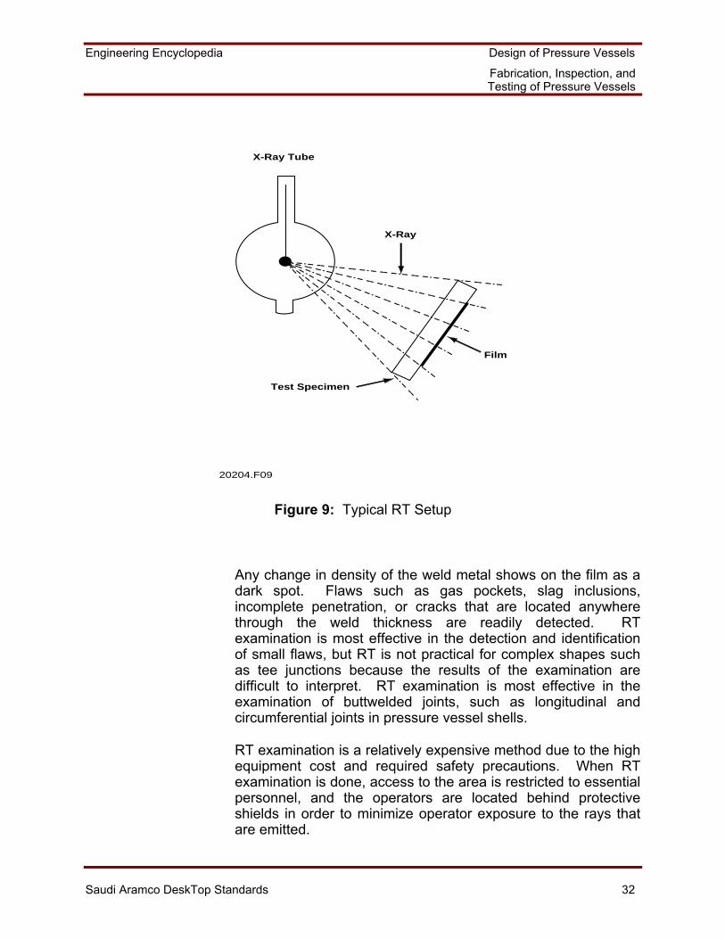
The most important NDE method is radiographic examination. In radiographic examination, a ray is emitted from a controllable source, penetrates a test specimen, and leaves an image on a strip of film that is mounted behind the test specimen. The major advantage of RT is that it produces a permanent record of the examination on film. Figure 9 shows a typical setup for RT examination.
Engineering Encyclopedia Design of Pressure Vessels
Fabrication, Inspection, and Testing of Pressure Vessels
Saudi Aramco DeskTop Standards 32
X-Ray Tube
X-Ray
Film
Test Specimen
20204.F09
Figure 9: Typical RT Setup
Any change in density of the weld metal shows on the film as a dark spot. Flaws such as gas pockets, slag inclusions, incomplete penetration, or cracks that are located anywhere through the weld thickness are readily detected. RT examination is most effective in the detection and identification of small flaws, but RT is not practical for complex shapes such as tee junctions because the results of the examination are difficult to interpret. RT examination is most effective in the examination of buttwelded joints, such as longitudinal and circumferential joints in pressure vessel shells.
RT examination is a relatively expensive method due to the high equipment cost and required safety precautions. When RT examination is done, access to the area is restricted to essential personnel, and the operators are located behind protective shields in order to minimize operator exposure to the rays that are emitted.
Engineering Encyclopedia Design of Pressure Vessels
Fabrication, Inspection, and Testing of Pressure Vessels
Saudi Aramco DeskTop Standards 33
Visual Inspection (VT)
A thorough visual inspection is usually satisfactory for minor structural welds, such as those that connect insulation support rings to a vessel shell. All weld surfaces that will be examined by more extensive means are first subject to VT. Visual weld inspection involves measuring the weld and noting any areas of obvious surface porosity, slag inclusions, weld undercut, or overlap. The VT provides an overall impression of weld quality and helps to locate areas where additional NDE should be performed.
Liquid Penetrant Examination (PT)
A liquid penetrant examination is used to detect weld surface-type defects. Defects which a PT examination may detect are cracks, seams, porosity, folds, inclusions, shrinkage, or any other surface defect. PT examination is used for both ferrous and nonferrous materials. The major limitation of PT examination is that it can only detect imperfections that are open to the surface. It cannot be used as the only examination tool for critical pressure-containing welds. PT is often used as the first and only step up from VT for relatively minor structural-type welds. In some cases, PT examination is done on intermediate weld passes for critical welds in order to detect and repair defects early before an entire weld is made. PT is often done on the weld root pass to ensure that the first weld pass is sound. PT is also often used after the final weld pass to find flaws that go through the weld surface, after which another inspection method is used to search for internal defects.
PT is relatively simple and is less expensive than RT, MT, or UT. The basic steps of a PT inspection are as follows:
(1) Surface Preparation and Cleaning: All surface coatings, such as paint and contaminants, must be completely removed since they could prevent the entrance of penetrant into the metal and could also prevent the identification of the flaw. Solvents are commonly used for surface preparation.
Engineering Encyclopedia Design of Pressure Vessels
Fabrication, Inspection, and Testing of Pressure Vessels
Saudi Aramco DeskTop Standards 34
(2) Penetrant Application: Liquid penetrant solutions have high fluidity, low viscosity, and high reliability to permit penetration into defects by capillary action. The liquid penetrant solutions also contain a fluorescent or visible dye to mark potential defect areas. Spraying is a common means of solution application. Adequate liquid penetration into any flaws generally takes 10 to 30 minutes, after which excess penetrant is removed.
(3) Removal of Excess Penetrant: Excess penetrant must be removed from the surface by wiping the surface with a clean cloth or equivalent. The penetrant must still be liquid at this stage rather than dried, or the entire process must be started again. The objective is to remove the penetrant from the weld surface without removing any penetrant that seeped into weld defects.
(4) Development: After excess penetrant has been removed, developer is immediately applied to make the flaws readily visible. By acceleration of the capillary bleed-out process, the developer helps detect penetrant that is retained in surface flaws. Development emphasizes the presence of a flaw by causing the penetrant that is retained in it to spread over a larger area. Development also acts as a color-contrasting background for the dye or fluorescent penetrants.
(5) Inspection and Evaluation: After development, the weld is inspected. Inspection is done in normal light when visible dye penetrants are used and in ultraviolet light when fluorescent dye penetrants are used. With either type of penetrant, both true and false indications may be revealed.
The standard true flaws that are indicated by PT include cracks, pits, and porosity. A large crack appears as a solid line of some width and becomes apparent soon after developer application. A cold-shut crack is an undersurface crack that bleeds to the surface. A cold-shut crack appears as a line of dots and comes to the surface a few minutes after the developer is applied. Porosity indications appear as dots and come to the surface almost immediately after developer application.
Engineering Encyclopedia Design of Pressure Vessels
Fabrication, Inspection, and Testing of Pressure Vessels
Saudi Aramco DeskTop Standards 35
False or nonrelevant indications are not caused by surface flaws. The primary reasons these false indications occur are poor PT application procedures or rough weld surfaces. The results of the PT are evaluated to determine if the flaws are real, to determine their extent and exact nature, and to determine if repairs are needed.
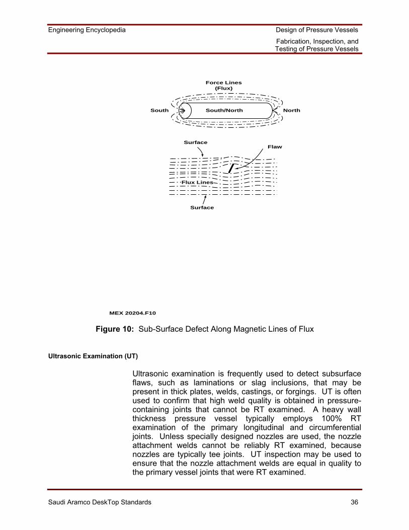
Magnetic Particle Test (MT)
The MT examination can detect cracks, porosity, and lack of fusion at or near the surface of ferromagnetic materials. Flaws that are up to 6 mm (1/4 in.) beneath the weld surface can be detected. MT depends on the magnetic properties of the material that is inspected and cannot be used on nonmagnetic materials. MT is frequently employed on the root and final weld passes or every 6 mm (1/4 in.) of weld buildup for critical welds where RT inspection is not practical (such as for nozzle attachment welds).
MT examination is based on the magnetic lines of flux (or force lines) that can be generated within a test piece. These force lines are parallel if no defects are present. If there is a defect, a small break in the force lines appears at the defect location. In MT examination, iron powder is applied to the surface and then the test piece is magnetized. If there are no defects, the iron powder is aligned in straight lines along the North-South magnetic flux lines. If there is a defect, the iron powder alignment is disturbed and flows around the defect. Figure 10 shows schematically how the iron powder is distributed at a defect during an MT examination.
Engineering Encyclopedia Design of Pressure Vessels
Fabrication, Inspection, and Testing of Pressure Vessels
Saudi Aramco DeskTop Standards 36
Force Lines
(Flux)
South NorthSouth/North
FlawSurface
Surface
Flux Lines
MEX 20204.F10
Figure 10: Sub-Surface Defect Along Magnetic Lines of Flux
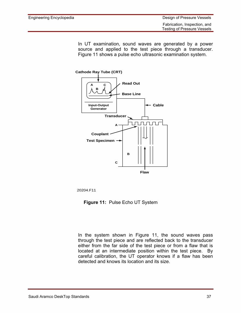
Ultrasonic Examination (UT)
Ultrasonic examination is frequently used to detect subsurface flaws, such as laminations or slag inclusions, that may be present in thick plates, welds, castings, or forgings. UT is often used to confirm that high weld quality is obtained in pressure-containing joints that cannot be RT examined. A heavy wall thickness pressure vessel typically employs 100% RT examination of the primary longitudinal and circumferential joints. Unless specially designed nozzles are used, the nozzle attachment welds cannot be reliably RT examined, because nozzles are typically tee joints. UT inspection may be used to ensure that the nozzle attachment welds are equal in quality to the primary vessel joints that were RT examined.
Engineering Encyclopedia Design of Pressure Vessels
Fabrication, Inspection, and Testing of Pressure Vessels
Saudi Aramco DeskTop Standards 37
In UT examination, sound waves are generated by a power source and applied to the test piece through a transducer. Figure 11 shows a pulse echo ultrasonic examination system.
Input-OutputGenerator
AB
C
B
A
C
Read Out
Base Line
Cable
Transducer
Couplant
Test Specimen
Flaw
Cathode Ray Tube (CRT)
20204.F11
Figure 11: Pulse Echo UT System
In the system shown in Figure 11, the sound waves pass through the test piece and are reflected back to the transducer either from the far side of the test piece or from a flaw that is located at an intermediate position within the test piece. By careful calibration, the UT operator knows if a flaw has been detected and knows its location and its size.
Engineering Encyclopedia Design of Pressure Vessels
Fabrication, Inspection, and Testing of Pressure Vessels
Saudi Aramco DeskTop Standards 38
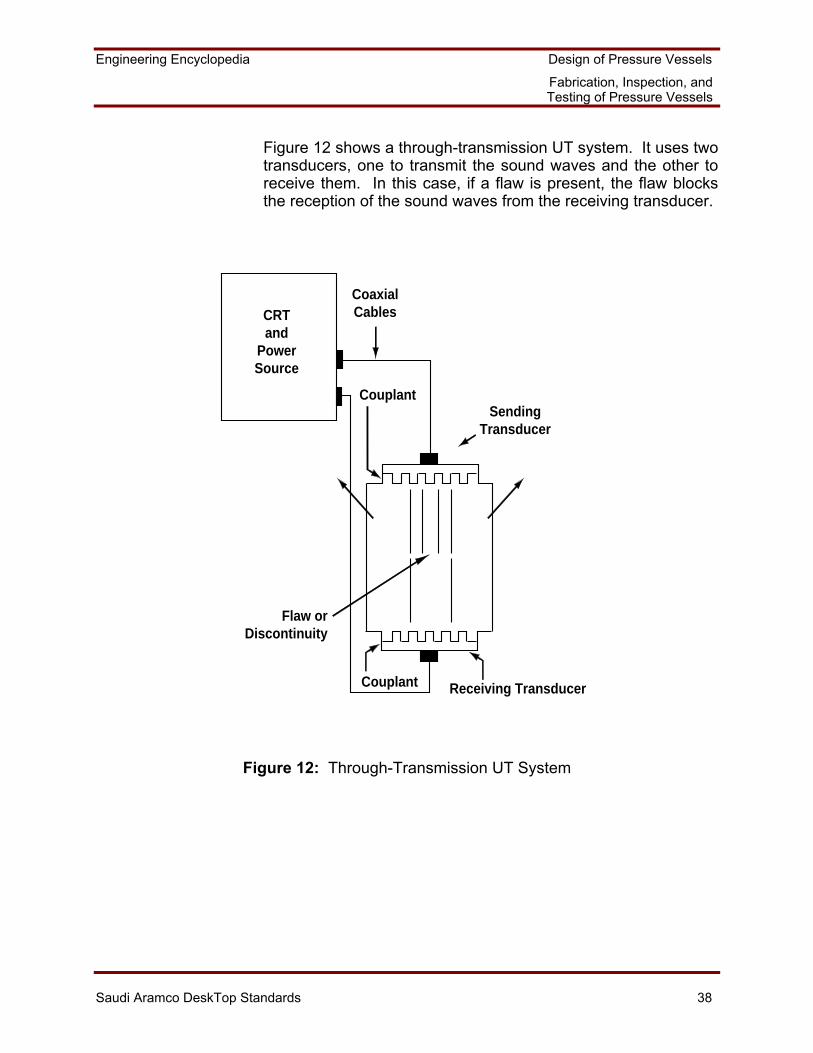
Figure 12 shows a through-transmission UT system. It uses two transducers, one to transmit the sound waves and the other to receive them. In this case, if a flaw is present, the flaw blocks the reception of the sound waves from the receiving transducer.
SendingTransducer
Couplant
Flaw orDiscontinuity
Receiving Transducer
CRTand
PowerSource
CoaxialCables
Couplant
Figure 12: Through-Transmission UT System
Engineering Encyclopedia Design of Pressure Vessels
Fabrication, Inspection, and Testing of Pressure Vessels
Saudi Aramco DeskTop Standards 39
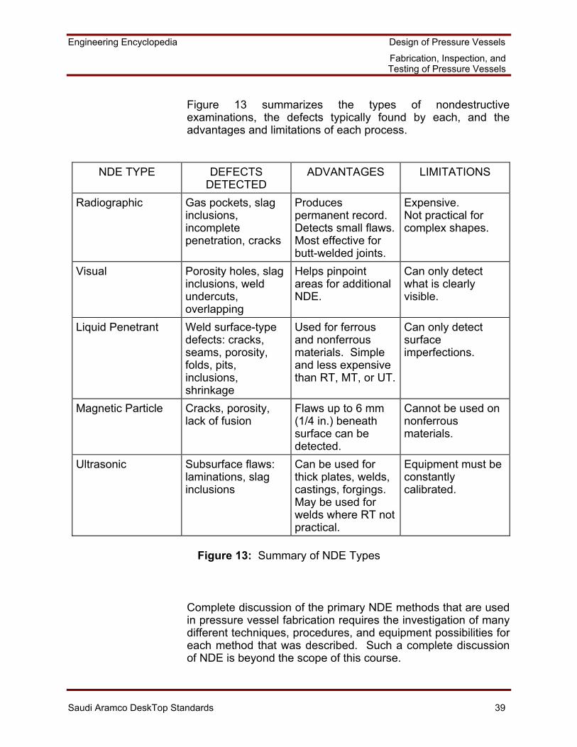
Figure 13 summarizes the types of nondestructive examinations, the defects typically found by each, and the advantages and limitations of each process.
NDE TYPE DEFECTS
DETECTED ADVANTAGES LIMITATIONS
Radiographic Gas pockets, slag inclusions, incomplete penetration, cracks
Produces permanent record. Detects small flaws.Most effective for butt-welded joints.
Expensive. Not practical for complex shapes.
Visual Porosity holes, slag inclusions, weld undercuts, overlapping
Helps pinpoint areas for additional NDE.
Can only detect what is clearly visible.
Liquid Penetrant Weld surface-type defects: cracks, seams, porosity, folds, pits, inclusions, shrinkage
Used for ferrous and nonferrous materials. Simple and less expensive than RT, MT, or UT.
Can only detect surface imperfections.
Magnetic Particle Cracks, porosity, lack of fusion
Flaws up to 6 mm (1/4 in.) beneath surface can be detected.
Cannot be used on nonferrous materials.
Ultrasonic Subsurface flaws: laminations, slag inclusions
Can be used for thick plates, welds, castings, forgings. May be used for welds where RT not practical.
Equipment must be constantly calibrated.
Figure 13: Summary of NDE Types
Complete discussion of the primary NDE methods that are used in pressure vessel fabrication requires the investigation of many different techniques, procedures, and equipment possibilities for each method that was described. Such a complete discussion of NDE is beyond the scope of this course.
Engineering Encyclopedia Design of Pressure Vessels
Fabrication, Inspection, and Testing of Pressure Vessels
Saudi Aramco DeskTop Standards 40
Type and Extent of Required Examination
The type and extent of examinations that are required for pressure vessel welds are specified by Saudi Aramco requirements and by the ASME Code. Requirements that are contained in Section VIII, Division 2 tend to be more stringent than Division 1 requirements. Participants should refer to Division 2 for details when required.
The ASME Code also specifies inspection procedures and acceptance criteria which must be followed. Work Aid 2A summarizes the steps which may be used to confirm that vessel vendor inspection plans meet Saudi Aramco and Division 1 requirements. The following paragraphs elaborate on several of these inspection requirements.
• SAES-W-010 requires that any pressure-containing weld that will not be hydrotested must be 100% radiographed. Such a situation is rare for pressure vessels. However, this situation could occur in very large field-fabricated vessels where the foundation has not been designed for the total water weight and where the vessel is not completely filled with water for field pressure testing.
• 32-SAMSS-004 requires UT examination as follows:
- All plates that are over 50 mm (2 in.) thick must be UT-examined. As plates get thicker, they are more prone to internal laminations which could be detrimental to vessel integrity after subsequent fabrication is done. For example, if attachment welds are made in the vicinity of a lamination, weld shrinkage stresses could cause a lamination to open further. Such opening of a lamination could also occur during plate forming.
- All plates that are over 50 mm (2 in.) thick must be
100% UT-examined for a distance of 150 mm (6 in.) back from a nozzle weld preparation or other cut-out. The presence of a lamination in these areas could lead to poor quality welds and/or high local stresses that were not considered in the vessel design calculations.
Engineering Encyclopedia Design of Pressure Vessels
Fabrication, Inspection, and Testing of Pressure Vessels
Saudi Aramco DeskTop Standards 41
- Clad steel plates must be UT-examined. UT examination is done to ensure that there is an acceptable bond between the cladding and base plate.
Pressure Test Plans
All pressure vessels that are designed to ASME Code requirements must be pressure tested after fabrication and inspection in order to demonstrate their structural integrity before they are placed into operation. The pressure test is made at a pressure that is higher than the design pressure. This excess pressure provides a safety margin since the vessel component stress levels during the test will be higher than the stress levels which will occur during operation. The objective of the pressure test is to bring the vessel to a high enough internal pressure, under controlled conditions, to demonstrate its mechanical integrity. Successful completion of the pressure test signifies that the vessel is acceptable for operation.
Pressure tests are typically made using water as the test medium because of the relative safety of water compared to a pneumatic test. The ASME Code permits performance of a pneumatic pressure test as an alternative to a hydrostatic test under certain circumstances. However, 32-SAMSS-004 specifies that all vessels except those in refrigerant service must be hydrotested. Vessels in refrigerant service must be either hydrotested and dried or must be pneumatically tested. SAES-A-004, Pressure Testing, prohibits a pneumatic pressure test without written approval from the Chief Inspection Engineer. SAES-A-004 also specifies general requirements for pressure testing.
Since the hydrostatic test will almost always be used, only the hydrostatic test will be discussed. Participants are referred to the ASME Code for pneumatic test requirements.
Engineering Encyclopedia Design of Pressure Vessels
Fabrication, Inspection, and Testing of Pressure Vessels
Saudi Aramco DeskTop Standards 42
32-SAMSS-004 requires that the pressure at the top of the vessel be determined by the rules of Paragraph UG-99 (c) for Division 1 vessels or by the rules of Paragraph AT-301 for Division 2 vessels. These ASME Code rules require that the hydrostatic test pressure at the top of the vessel be calculated by multiplying the "calculated test pressure" for each element by 1.5 and by reducing the value by the hydrostatic head on that element. The "calculated test pressure" for each element is determined based on the appropriate equation for MAWP that was discussed in MEX 202.03, the nominal component thickness which includes corrosion allowance, the appropriate weld joint efficiency, and the material allowable stress at test temperature. The Pressure Vessel Design Sheet (Form 9527) also contains the required equations. Work Aid 2B may be used to help determine if the hydrotest pressure that is specified by a vendor is correct. Use of this pressure level for the hydrotest permits potential use of the vessel up to its MAWP without the need for a new hydrotest.
Form 9527 contains areas that directly relate to determination of the required hydrotest pressure. Refer to the copy of Form 9527 that is contained in Course Handout 3 and note the following:
• Hydrotest pressures must be calculated for the shop test with the vessel in the horizontal position, for the field test with the vessel in the final position and with uncorroded component thicknesses, and for the field test with the vessel in the final position and with corroded component thicknesses.
• The basis for calculation of the initial test pressure for the
vessel in the shop is the lower of the pressure calculated for the shell or the pressure calculated for the heads.
• The shop hydrotest pressure must also consider the
permitted hydrotest pressure of any flanged connections. The calculated hydrotest pressure cannot exceed the test pressure of the flanged connections.
Engineering Encyclopedia Design of Pressure Vessels
Fabrication, Inspection, and Testing of Pressure Vessels
Saudi Aramco DeskTop Standards 43
SAES-D-001 and 32-SAMSS-004 require that, during the pressure test, the stress at any section of the vessel cannot exceed 90% of the material minimum specified yield strength (MSYS), based on use of the design weld joint efficiency (E). The stress in the vessel is limited to 90% of the MSYS to ensure that there is an adequate safety margin before permanent deformation in vessel components can occur. Also recall that a reduced wind must be considered to act during the field hydrotest, based on 32-SAMSS-004 requirements.
The requirement to design the vessel for field hydrotest introduces a complication, especially for tall towers. A tall tower is typically designed for a specific liquid level (design high liquid level) as part of its normal design conditions. However, the specific gravity of the design liquid is normally less than 1.0, and the design high liquid level is usually much lower than the top of the tower. During a field hydrotest, water at a specific gravity of 1.0 is used, and the tower is filled to the top. The larger specific gravity and fill height of hydrotest water results in a higher weight and hydrostatic head load than occurs during normal operation. Therefore, to withstand the hydrotest loads in some cases, thicker plates are required for lower sections of the tower than would be required for the operational loads.
There are situations where one pressure vessel may have two or more individual sections that are separated by intermediate heads. Each vessel section must typically be designed for a separate hydrotest. Each separate hydrotest could affect the intermediate head design because the head is exposed to a higher weight and hydrostatic test pressure than would occur during normal operation.
The paragraphs that follow summarize additional general hydrostatic test requirements that are based on the ASME Code, Section VIII, Division 1.
• If visible, permanent distortion of the vessel occurs during hydrotest, the ASME Authorized Inspector has the right to reject the vessel. Permanent distortion should not occur as long as the design is correct and the test pressure does not exceed the value that was calculated on the basis described above.
Engineering Encyclopedia Design of Pressure Vessels
Fabrication, Inspection, and Testing of Pressure Vessels
Saudi Aramco DeskTop Standards 44
• Pressure chambers of combination units that are designed to operate independently must be hydrotested as separate vessels: that is, each chamber must be tested without pressure in the other chambers. In addition: - If the common elements are designed for a higher
differential pressure than the MAWP's of the adjacent chambers, then the hydrotest of the common elements must subject them to at least 1.5 times their design differential pressure, corrected for the effect that design temperature has on material allowable stress. The allowable stress correction is equal to the ratio of the material allowable stress at test temperature to the allowable stress at design temperature.
- If the common elements are designed for the
maximum differential pressure that can occur, and if this pressure is less than the higher pressure in the adjacent chambers, then their common elements must have a hydrotest pressure that is at least 1-1/2 times the differential pressure that is marked on the unit, corrected for temperature.
After testing and inspection of the common elements, the
adjacent chambers are then hydrotested simultaneously. Care must be taken to limit the differential pressure between the chambers to the pressure that is used when testing the common elements.
• All joints and connections must be inspected after
application of the hydrotest pressure. This inspection must be made at a pressure that is not less than 2/3 of the test pressure.
• The metal temperature during hydrotest should be
maintained at least 17°C (30°F) above the minimum design metal temperature but not over 49°C (120°F). The minimum metal temperature is specified to minimize the risk of brittle fracture. The test pressure must not be applied until the vessel and water are at about the same temperature.
Engineering Encyclopedia Design of Pressure Vessels
Fabrication, Inspection, and Testing of Pressure Vessels
Saudi Aramco DeskTop Standards 45
• Vents must be provided at all vessel high points (based on test position) to purge possible air pockets while the vessel is filled with water.
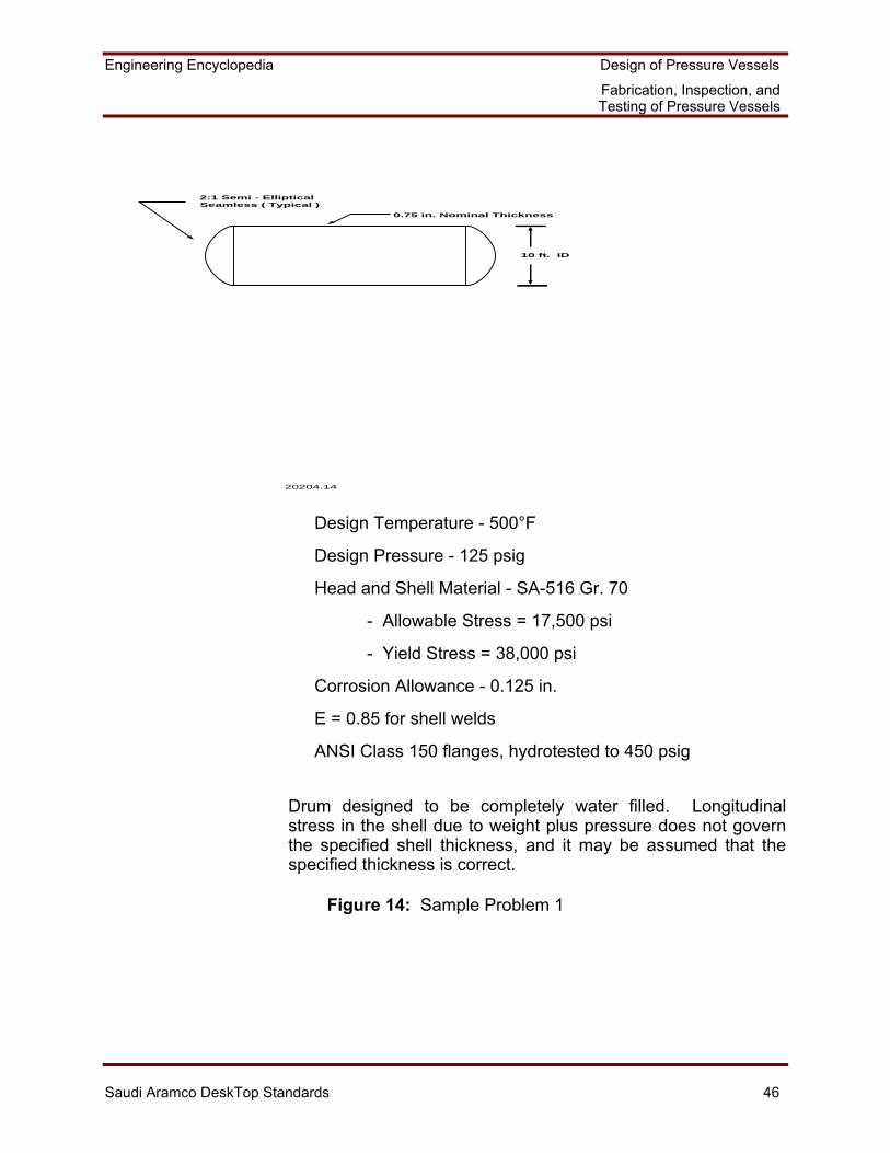
Sample Problem 1: Calculation of the Required Hydrotest Pressure
The horizontal drum that is described in Figure 14 is being supplied to Saudi Aramco.
Determine the required hydrotest pressures for the new vessel in the shop and field. Also determine the required service test pressure with the vessel corroded. Work Aid 2B may be used to help solve this problem.
Engineering Encyclopedia Design of Pressure Vessels
Fabrication, Inspection, and Testing of Pressure Vessels
Saudi Aramco DeskTop Standards 46
2:1 Semi - EllipticalSeamless ( Typical )
0.75 in. Nominal Thickness
10 ft. ID
20204.14
Design Temperature - 500°F
Design Pressure - 125 psig
Head and Shell Material - SA-516 Gr. 70
- Allowable Stress = 17,500 psi
- Yield Stress = 38,000 psi
Corrosion Allowance - 0.125 in.
E = 0.85 for shell welds
ANSI Class 150 flanges, hydrotested to 450 psig
Drum designed to be completely water filled. Longitudinal stress in the shell due to weight plus pressure does not govern the specified shell thickness, and it may be assumed that the specified thickness is correct.
Figure 14: Sample Problem 1
Engineering Encyclopedia Design of Pressure Vessels
Fabrication, Inspection, and Testing of Pressure Vessels
Saudi Aramco DeskTop Standards 47
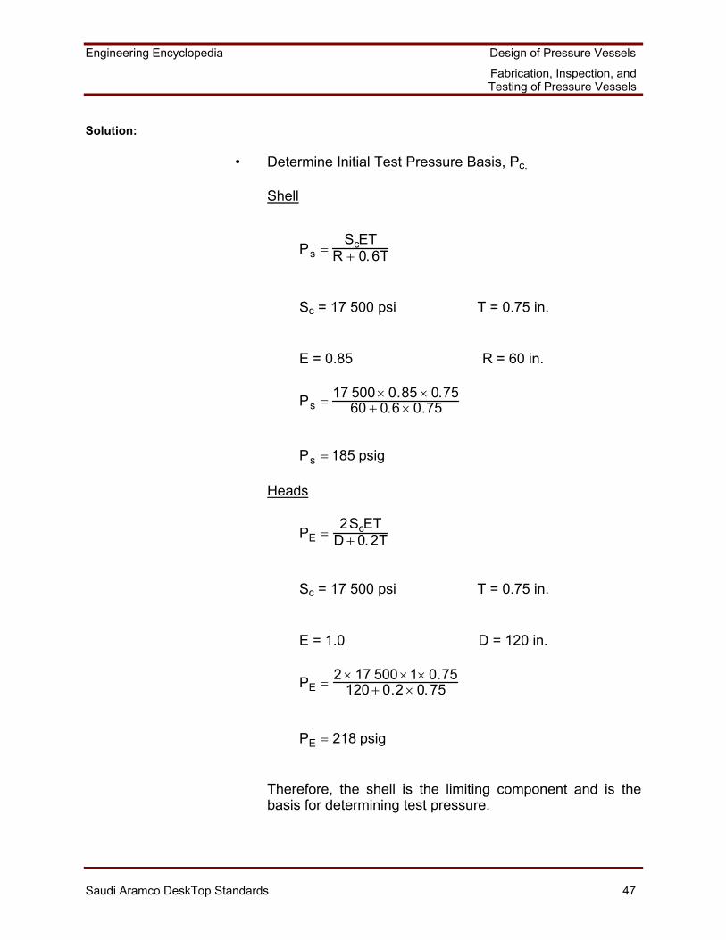
Solution:
• Determine Initial Test Pressure Basis, Pc.
Shell
Ps =ScET
R + 0. 6T
Sc = 17 500 psi T = 0.75 in.
E = 0.85 R = 60 in.
Ps = 17 500 × 0.85 × 0.7560 + 0.6 × 0.75
Ps = 185 psig
Heads
PE =2ScET
D + 0. 2T
Sc = 17 500 psi T = 0.75 in.
E = 1.0 D = 120 in.
PE = 2 × 17 500 ×1× 0.75120 + 0.2 × 0. 75
PE = 218 psig
Therefore, the shell is the limiting component and is the basis for determining test pressure.
Engineering Encyclopedia Design of Pressure Vessels
Fabrication, Inspection, and Testing of Pressure Vessels
Saudi Aramco DeskTop Standards 48
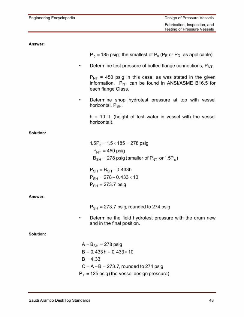
Answer:
Pc = 185 psig; the smallest of Ps (PE or PD, as applicable).
• Determine test pressure of bolted flange connections, PNT.
PNT = 450 psig in this case, as was stated in the given information. PNT can be found in ANSI/ASME B16.5 for each flange Class.
• Determine shop hydrotest pressure at top with vessel horizontal, PSH.
h = 10 ft. (height of test water in vessel with the vessel horizontal).
Solution:
1.5Pc = 1.5 ×185 = 278 psigPNT = 450 psigBSH = 278 psig (smaller of PNT or 1.5Pc )
PSH = BSH − 0.433hPSH = 278 − 0.433 ×10PSH = 273.7 psig
Answer:
PSH = 273.7 psig, rounded to 274 psig
• Determine the field hydrotest pressure with the drum new and in the final position.
Solution:
A = BSH = 278 psigB = 0. 433 h = 0.433 ×10B = 4.33C = A −B = 273. 7, rounded to 274 psig
PT = 125 psig (the vessel design pressure)
Engineering Encyclopedia Design of Pressure Vessels
Fabrication, Inspection, and Testing of Pressure Vessels
Saudi Aramco DeskTop Standards 49
D = 1. 5PT = 1.5 ×125 = 187. 5B = 4. 33E = D +B = 191.83, rounded to 192 psig at the bottom of the vessel
Answer:
Therefore, test pressure at the top = 274 psig (the higher of C or D). Note that the shop and field test pressures with the vessel new are equal in this case since this is a horizontal drum and since the hydrostatic head pressures from the water are equal. This would not be the case for a tall tower which is hydrotested horizontally in the shop but vertically in the field.
• Confirm that the stress in the limiting component does not exceed 0.9 of the minimum specified yield strength times the weld joint efficiency, E.
Solution:
Since the shell is the limiting component, we only need to check its stress:
S =P R + 0.6T( )
ET
Note that the pressure used is at the bottom of the limiting component.
S =278 60 + 0.6 ×0.75( )
0. 85 × 0.75S = 26 361psi0.9 × 38 000 = 34 200 psi
Answer:
Since S < 34 200 psi, the hydrotest pressure is acceptable. Note that E was accounted for already in the equation.
• Determine service test pressure at the top of the vessel with the vessel corroded and confirm that the stress in the vessel does not exceed 0.9 of the minimum specified yield strength times E.
Engineering Encyclopedia Design of Pressure Vessels
Fabrication, Inspection, and Testing of Pressure Vessels
Saudi Aramco DeskTop Standards 50
Service Test Pressure = 1. 5 ×PT = 187. 5 psig:
P = 192 psig at shell bottom T = 0.75 - 0.125 = 0.625 in., corroded thickness
Solution:
S =P R + 0.6T( )
ET
S =192 60.125 + 0.6 × 0.625( )
0.85 × 0.625
Answer:
S = 21 865 psi < 0.9 × 38 000 = 34 200 psi
Therefore, the vessel is acceptable.
Hardness Test Plans
Hardness in metals is defined as the ability to resist the penetration of the metallic surface. Hardness can be readily measured, is directly proportional to material strength, and is inversely proportional to ductility and toughness. Therefore, the harder a material is, the more prone it will be to cracking or brittle fracture. Hardness is affected by material chemistry and microstructure and is thus greatly influenced by the heat of welding. Therefore, there will be a variation in hardness across the base metal, weld metal, and HAZ of welded components due to local variations in chemistry (especially carbon content), welding technique, and preheat temperature. Welding procedure changes and PWHT are often done to reduce weld hardness when hardness reduction is needed due to material and/or service considerations.
The Brinell, Vickers, and Rockwell methods are the most common approaches that are used to measure hardness. It is also possible to convert hardness measurements that are taken using one method into equivalent values on the other hardness measurement scales. Discussion of such conversions is beyond the scope of this course. The paragraphs that follow briefly describe the Brinell and Vickers hardness measurement methods, since Saudi Aramco requires these methods.
Engineering Encyclopedia Design of Pressure Vessels
Fabrication, Inspection, and Testing of Pressure Vessels
Saudi Aramco DeskTop Standards 51
Brinell Hardness Test
In the Brinell test, a steel ball that is 10 mm (3/8 in.) in diameter is pressed into the surface of the metal with a load of 3 000 kg (6 614 lb.). The diameter of the impression that is made in the metal surface is then measured through the use of a special microscope. The diameter of the impression is converted to the Brinell hardness number (BHN) by consulting a table. For example, soft iron is about 100 BHN, and file-hard steel about 600 BHN. A portable Brinell hardness tester, which uses a much lighter weight to make the indentation, is used for hardness testing of production welds in a pressure vessel.
Vickers Hardness Test
The Vickers hardness test employs a similar principle as the Brinell test in that the Vickers test expresses the results in terms of the pressure under the indentor and uses the same units. However, the indentor is a diamond that is shaped as a square pyramid, the loads are lighter and vary between 1 and 120 kg (2.2 - 265 lb.), and the impression is measured using a medium-power compound microscope. The Vickers method is more flexible and is considered to be more accurate than either the Brinell or Rockwell methods. However, the equipment is more expensive, and the other methods are faster for production work.
Hardness Test Results
The ASME Code does not have weld hardness testing requirements or limitations. However, SAES-W-010 and 32-SAMSS-004 have weld hardness testing requirements. SAES-W-010 specifies when hardness testing must be done for pressure vessels and also specifies the acceptable hardness limits.
Work Aid 2C provides a checklist which may be used to help confirm that vessel vendor hardness test plans meet Saudi Aramco requirements. Hardness test requirements are specified for both the welding procedure qualification welds and the vessel production welds. The paragraphs that follow elaborate on several of these hardness test requirements.
Engineering Encyclopedia Design of Pressure Vessels
Fabrication, Inspection, and Testing of Pressure Vessels
Saudi Aramco DeskTop Standards 52
• The Vickers hardness test procedure must be used for welding procedure qualification welds for vessels that are in sour service
except for specified exemptions. However, the exemptions must still comply with all NACE MR-01-75 hardness levels and test requirements. Hardness testing is required for this application since hard welds are prone to cracking in sour service.
One of the exemptions from hardness testing is if all vessel internal surfaces are clad or weld-overlaid with austenitic stainless steel or nickel-based alloys. In this case, the cladding or overlay shields the ferritic base plate from the sour fluid. Partial or complete strip lining, partial cladding, or partial overlay are not exempt from hardness testing.
Another exemption from hardness testing is if the weld procedure is used only for external structural attachments and the vessel wall at the attachment point is at least 25 mm (1.0 in.) thick. In this case, the weld HAZ will not extend to the vessel inside surface and thus will not be affected by the sour fluid.
• The weld procedure qualification welds must also be hardness-tested for vessels in any service if the wall thickness is greater than 38 mm (1.5 in), except for vessels that are made from austenitic stainless steel or nickel-based alloys, and except when the weld procedure is used only for external structural attachment welds. The concern here is that the high heat inputs that are required to make heavy welds could cause the welds to be hard and more prone to cracking under service loads.
PWHT may be required for specific materials and/or thicknesses in order to meet the hardness limits that are specified by Saudi Aramco.
Engineering Encyclopedia Design of Pressure Vessels
Fabrication, Inspection, and Testing of Pressure Vessels
Saudi Aramco DeskTop Standards 53
SAES-W-010 also requires hardness testing of the production welds for all vessels that are in sour service, regardless of material, to ensure that the production welds consistently have acceptable hardness levels. The Brinell hardness test is used in this case because it is generally quicker and less expensive for production hardness testing than the other hardness testing methods.
SAES-W-001 specifies hardness testing procedural requirements as follows:
• Hardness testing of welding procedure qualification coupons must conform to Standard Drawing AB-036386 (W), Hardness Testing for Welding Procedure Qualifications.
• Production weld hardness testing, when specified, must
meet the following requirements:
- Testing must be done with a portable hardness tester (TeleBrinell or approved equivalent). The Brinell scale must be used unless another scale is approved by Saudi Aramco.
- The weld must be ground to a smooth flat surface for
testing. This smoothing is required to obtain an accurate hardness measurement.
- Hardness indentations must be made at or near the
middle of the weld bead. This indentation location will give an average hardness reading that is a composite of the weld metal, base metal, and HAZ (considering the size of the indentor that is used).
- Hardness retesting may be performed within specified
limits if the original hardness test results are too high.
The Saudi Aramco hardness testing requirements ensure that weld hardness is considered in the weld procedure qualification tests when appropriate. The hardness tests then confirm that the hardness of the actual production welds is acceptable for sour service.
Engineering Encyclopedia Design of Pressure Vessels
Fabrication, Inspection, and Testing of Pressure Vessels
Saudi Aramco DeskTop Standards 54
Impact Test Plans
Material toughness, brittle fracture, Charpy impact testing, and the ASME Code exemption curves were discussed in MEX 202.02. Also recall that 32-SAMSS-004 requires that ASME exemption criteria and impact test procedures must be used for both Division 1 and Division 2 pressure vessels. Therefore, once it is determined that the material cannot be exempt from impact testing, the vendor's impact test plans must be based on both Division 2 and Saudi Aramco requirements.
Work Aid 2D contains a checklist which may be used to confirm that vendor impact test plans meet Saudi Aramco requirements. The paragraphs that follow highlight several Saudi Aramco and Division 2 requirements. Participants are referred to Division 2 for additional details. Unless otherwise noted, the stated requirements are from Division 2.
• Requirements for impact test procedures and apparatus are specified.
• Each set of impact tests must consist of three specimens
of a specified size. Unless otherwise specified, plate specimens may be oriented with the specimen length parallel to the final direction of rolling. With this orientation, impact energies will be measured in the direction in which the plate will tend to be tougher.
• Certified impact test reports by the materials manufacturer
are acceptable provided that either of the following conditions are met:
- The specimens are representative of the material that
was delivered and the vessel fabrication will not reduce the impact properties of the material.
- The materials from which the specimens are removed
are heat treated separately such that they are representative of the material in the finished vessel.
This approach ensures that the basic materials are
acceptable before they arrive at the vessel vendor and provides earlier materials quality control. The material "as-tested" must then be confirmed to be equivalent to the material "as-fabricated."
Engineering Encyclopedia Design of Pressure Vessels
Fabrication, Inspection, and Testing of Pressure Vessels
Saudi Aramco DeskTop Standards 55
As an alternative to this confirmation, the vessel manufacturer may do the impact testing.
• Minimum required Charpy V-notch impact energy values are specified. These values are stated both as the average value for the three specimens and the minimum value for any one specimen. Acceptable impact energy values are specified as a function of tensile strength, and higher values are required as the tensile strength increases. Higher strength steels are more prone to brittle fracture than lower strength steels, all other parameters being equal. Therefore, higher strength steels must achieve higher impact energy values in order to have adequate fracture toughness.
• 32-SAMSS-004 requires that the impact test temperature
must be 18°C (32°F) below the minimum design temperature that is specified on the Pressure Vessel Design Data Sheet Form 9527. This approach provides an extra margin of safety against brittle fracture. When impact testing is required, it must include the base metal, weld metal, and HAZ.
• SAES-W-010 contains the following items related to impact
tests:
- For any flux, Gas Metal Arc Welding (GMAW) electrode or for any Flux Cored Arc Welding (FCAW) electrode that is used for welding procedures with impact toughness requirements, the specified brand, type, and maximum size used for the Procedure Qualification Record (PQR) must be used in the actual fabrication.
- Welding procedures with impact test requirements
must be submitted by the Inspection Department to the Consulting Services Department for final review and approval. This approach provides additional review to ensure that material toughness is adequately considered in the weld procedure.
Engineering Encyclopedia Design of Pressure Vessels
Fabrication, Inspection, and Testing of Pressure Vessels
Saudi Aramco DeskTop Standards 56
Applicable Codes and Standards
The codes and standards that apply to the evaluation of vendor inspection and testing plans were discussed throughout the prior sections of this module. These codes and standards include the following: • ASME Code, Section VIII (Division 1 or 2, as appropriate) • ASME Code, Section IX • SAES-D-001, Pressure Vessels • SAES-W-010, Welding Requirements for Pressure Vessels • 32-SAMSS-004, Pressure Vessels Work Aid 2 may be used to help determine whether vendor inspection and testing plans meet Saudi Aramco requirements.
Engineering Encyclopedia Design of Pressure Vessels
Fabrication, Inspection, and Testing of Pressure Vessels
Saudi Aramco DeskTop Standards 57
SUMMARY
This module discussed welding fundamentals, types of welded joints, welding procedures and welder qualification, and acceptable welding techniques. It has also identified the acceptable welding details and fabrication tolerances for pressure vessel components that are contained in the Saudi Aramco SAESs and SAMSSs, and in the ASME Code. These requirements will enable the Participant to correctly evaluate fabrication drawings for acceptability. The second section of this module discussed methods of examination; type and extent of required examination; pressure, hardness, and impact test plans; and the applicable codes and standards which will enable the Participant to determine whether vendor inspection and testing plans satisfy Saudi Aramco requirements.
This module completes discussion of the requirements that must be met for a new pressure vessel. MEX 202.05 will discuss maintenance and repair requirements for existing pressure vessels.
Engineering Encyclopedia Design of Pressure Vessels
Fabrication, Inspection, and Testing of Pressure Vessels
Saudi Aramco DeskTop Standards 58
WORK AID 1: STEPS, DRAWINGS, AND CODE (SAES-W-010) AND PROCESS REQUIREMENTS FOR EVALUATING FABRICATION DRAWINGS FOR ACCEPTABILITY
This Work Aid may be used to evaluate fabrication drawings for suitability, and takes the form of a checklist with appropriate references. Figure references that are noted are in the ASME Code, Section VIII, Division 1, unless stated otherwise. Reference should be made to the classroom copies of the ASME Code, Section VIII, Division 1 in Course Handout 1, and SAES-W-010 in Course Handout 2, in conjunction with this Work Aid.
1. Vendor fabrication drawings are to reference the ASME Code, Section VIII, Division 1, and 32-SAMSS-004, Pressure Vessels. This reference should generally be sufficient confirmation that the vendor intends to follow the fabrication requirements that are contained in these documents, unless there is specific information to the contrary. For example, dimensional tolerances will typically not be shown on vendor drawings, but must meet ASME requirements.
2. Shell and head pressure-containing welds are to be full penetration and full fusion.
3. Shell and head joint details are to be consistent with weld joint categories that are used in the vessel design in accordance with Figure UW-12.
4. Nozzle attachments are to be full-penetration welds.
5. Nozzles and manholes that extend into clad vessels are to be in accordance with Standard Drawing AB-036367 (Reference Course Handout 3).
6. Reinforcing pad attachment welds are to be at least 50 mm (2 in.) from head-to-shell welds.
7. A 6 mm (1/4 in.) NPS weep hole is to be in all reinforcement or other plates that are welded to the shell.
8. Support skirts are to be welded to the vessel heads such that the skirt centerline aligns with the head straight flange centerline. This requirement is not applicable to hemispherical heads.
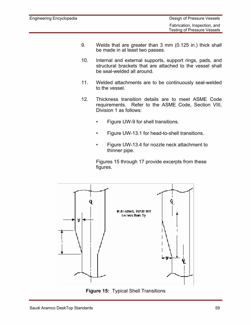
Engineering Encyclopedia Design of Pressure Vessels
Fabrication, Inspection, and Testing of Pressure Vessels
Saudi Aramco DeskTop Standards 59
9. Welds that are greater than 3 mm (0.125 in.) thick shall be made in at least two passes.
10. Internal and external supports, support rings, pads, and structural brackets that are attached to the vessel shall be seal-welded all around.
11. Welded attachments are to be continuously seal-welded to the vessel.
12. Thickness transition details are to meet ASME Code requirements. Refer to the ASME Code, Section VIII, Division 1 as follows:
• Figure UW-9 for shell transitions. • Figure UW-13.1 for head-to-shell transitions. • Figure UW-13.4 for nozzle neck attachment to
thinner pipe.
Figures 15 through 17 provide excerpts from these figures.
Figure 15: Typical Shell Transitions
Engineering Encyclopedia Design of Pressure Vessels
Fabrication, Inspection, and Testing of Pressure Vessels
Saudi Aramco DeskTop Standards 60
Tangent lineTh
inn
er p
art
y
y
Th
inn
er p
art
y
I
Tangent line
Th
inn
er p
art
y
I
Tangent line
Th
inn
er p
art
................
. . . . .. . . . .. . . . .. . . . .
FilletWeld
Butt Weld
Intermediate Head Attachment
I I
th th
ts ts
th th
ts ts
Figure 16: Typical Head-to-Shell Transitions
Engineering Encyclopedia Design of Pressure Vessels
Fabrication, Inspection, and Testing of Pressure Vessels
Saudi Aramco DeskTop Standards 61
Figure 17: Nozzle Neck Attachment to Thinner Pipe
13. Nozzle attachment details shall be in accordance with
Figure UW-16.1, except that only details that use full-penetration welds are acceptable. Typical nozzle attachment details from this figure were illustrated in MEX 202.03.
14. Stiffener ring attachment details shall be in accordance with Figure UG-30. See Figure 18.
Figure 18: Stiffener Ring Attachment 15. Weld procedure requirements shall be as follows:
• A weld procedure is required for each weld type and shall meet ASME requirements.
Engineering Encyclopedia Design of Pressure Vessels
Fabrication, Inspection, and Testing of Pressure Vessels
Saudi Aramco DeskTop Standards 62
• A weld map or equivalent is to be provided that relates each weld in the vessel to the required weld procedure.
• Weld procedure test requirements shall be in
accordance with SAES-W-010, Welding Requirements for Pressure Vessels. Vessel fabrication documentation should reference SAES-W-010, or the weld procedure test requirements should be explicitly stated within the documentation.
• Minimum preheat temperature shall the greater of:
- 20°C (68°F)
- Appendix R of the ASME Code
- The preheat listed in Standard Drawing AE-036451(W) for field fabrication or repair of P-No. 1 carbon steel material. (Reference Course Handout 3).
• PWHT shall be based on the ASME Code, Para. UCS-56 for carbon and low-alloy steels. PWHT is also required for the following services in accordance with SAES-W-010, Welding Requirements for Pressure Vessels:
- Caustic soda (NaOH) solutions, in accordance
with Standard Drawing AE-036208 (W)
- Monoethanolamine (MEA) solutions at all temperatures
- Diglycolamine (DGA) solutions above 138°C (280°F) design temperature
- Rich amino disopropanol (ADIP) solutions above 90°C (194°F) design temperature
- Lean ADIP solutions above 60°C (140°F) design temperature
- Deaerator service
16. Welder qualifications are to meet ASME requirements.
Engineering Encyclopedia Design of Pressure Vessels
Fabrication, Inspection, and Testing of Pressure Vessels
Saudi Aramco DeskTop Standards 63
WORK AID 2: STEPS FOR DETERMINING WHETHER VENDOR INSPECTION AND TESTING PLANS SATISFY SAUDI ARAMCO REQUIREMENTS
This Work Aid may be used in conjunction with the class reference copies of the ASME Code in Course Handout 1, and the SAESs in Course Handout 2, to determine whether vendor inspection and testing plans satisfy Saudi Aramco requirements.
Work Aid 2A: Procedure for Inspection Plans
Use the steps that follow to confirm that the inspection plans that are proposed by pressure vessel vendors meet Saudi Aramco requirements for Division 1 pressure vessels. All the requirements are based on Division 1, except where a Saudi Aramco source document is noted.
1. Vendor fabrication drawings are to reference the ASME Code, Section VIII, Division 1, and 32-SAMSS-004, Pressure Vessels.
2. As a minimum, the extent of radiography is to be consistent with the weld joint type, category, and joint efficiency that were employed in the design calculations in accordance with Table UW-12 of the ASME Code.
3. Full radiography is also required for the following cases even if not required by Step 2:
• Shell and head butt welds for vessels that are in lethal service.
• Butt welds which exceed the following nominal
thicknesses:
- 32 mm (1 1/4 in.) for P-No. 1 material (carbon steel)
- 19 mm (3/4 in.) for P-No. 3 material (C-1/2 Mo
through 1/2 Cr-1/2 Mo) - 16 mm (5/8 in.) for P-No. 4 material (such as 1
1/4 Cr - 1/2 Mo)
Engineering Encyclopedia Design of Pressure Vessels
Fabrication, Inspection, and Testing of Pressure Vessels
Saudi Aramco DeskTop Standards 64
- All thicknesses for P-No. 5 material (such as 2 1/4 Cr - 1 Mo)
- 38 mm (1 1/2 in.) for austenitic stainless steels
• Shell and head butt welds in unfired steam boilers that are over 345 kPa (50 psig) design pressure.
• Butt welds in nozzles and communicating chambers
that are attached to vessel sections or heads that must be fully radiographed due to lethal or steam boiler service. Exception: Category B and C butt welds that do not exceed NPS 10 or 29 mm (1 1/8 in.) thickness do not require radiography.
• Butt welds that are joined by electrogas welding with
any single pass that is over 38 mm (1 1/2 in.). • Butt welds that are joined by electroslag welding. • All butt welds in vessels with a minimum design
temperature below 0°C (32°F), or are in wet, sour service (SAES-D-001 and 32-SAMSS-004).
• Welds that are located under reinforcing pads (32-
SAMSS-004). • Pressure-containing welds that will not be hydrotested
(SAES-W-010). • Category A and B welds that are made from one side,
or are located in shell components that are over 75 mm (3 in.) thick (SAES-W-010).
4. UT examination is required as follows:
• As a substitute for RT for the final closure seam if the vessel construction is such that a radiograph cannot be interpreted.
• Electrogas welds that are in ferritic material with any
single pass over 38 mm (1 1/2 in.). UT examination shall be done after heat treatment.
• Electroslag welds that are in ferritic material. UT
examination shall be done after heat treatment.
Engineering Encyclopedia Design of Pressure Vessels
Fabrication, Inspection, and Testing of Pressure Vessels
Saudi Aramco DeskTop Standards 65
• Welds that are made by the electron beam process. • Welds that are made by inertia and continuous drive
friction process that are full- or spot-radiographed. • Plate that is over 50 mm (2 in.) thick. UT examination
shall be done in accordance with ASTM A578, Level I (32-SAMSS-004).
• Plate that is over 50 mm (2 in.) thick, for a distance of
150 mm (6 in.) back from a nozzle weld preparation, or other cut-out (32-SAMSS-004).
• Clad steel plate. UT examination shall be done in
accordance with ASTM A578, supplementary requirement S7 (32-SAMSS-004).
• For vessels that are over 75 mm (3 in.) thick (SAES-
W-010):
- All Category A and B welds - All nozzle attachment welds that exceed 25 mm
(1 in.) throat thickness that cannot be radiographed
- Any nozzle attachment welds that exceed 50 mm
(2 in.) throat thickness, in addition to any other inspection
All UT procedures and acceptance criteria are to be in accordance with Appendix 12 of Division 1.
5. Magnetic particle and/or liquid penetrant examination is
required as follows:
• When a pressure part is welded to a flat plate that is thicker than 13 mm (1/2 in.) and forms a corner joint:
- Flat plate weld joint preparation is to be MT- or
PT-examined before welding. - MT or PT examination of the peripheral edge of
the flat plate, and any remaining exposed surface of weld joint preparation, after welding.
Engineering Encyclopedia Design of Pressure Vessels
Fabrication, Inspection, and Testing of Pressure Vessels
Saudi Aramco DeskTop Standards 66
• MT (or PT if nonmagnetic) examination of structural attachment welds that are made to pressurized components that are not hydrotested after making the weld (SAES-W-010).
• Except for nonferromagnetic materials, wet
fluorescent MT using AC yoke is required for (SAES-W-010):
- All internal welds, including temporary weld
areas, for vessels that are in sour service - All internal and external welds of 25 mm (1 in.) or
greater thickness that are made by the Shielded Metal Arc Welding (SMAW) process
• For vessels over 75 mm (3 in.) thick, wet fluorescent
MT (PT for nonferromagnetic material) examination for all welds, including temporary attachment welds (SAES-W-010).
Work Aid 2B: Procedure for Pressure Test Plans
The pressure test shall be made using water, unless a pneumatic pressure test is approved by the Chief Inspection Engineer. The required test pressure at the top of the vessel must be specified for the cases that follow:
- Shop hydrotest with the vessel horizontal - Field hydrotest with the vessel in its final position and
uncorroded component thicknesses - Field hydrotest with the vessel in its final position and
corroded component thicknesses
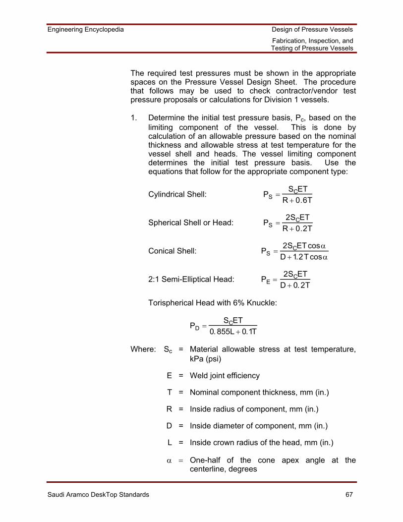
Engineering Encyclopedia Design of Pressure Vessels
Fabrication, Inspection, and Testing of Pressure Vessels
Saudi Aramco DeskTop Standards 67
The required test pressures must be shown in the appropriate spaces on the Pressure Vessel Design Sheet. The procedure that follows may be used to check contractor/vendor test pressure proposals or calculations for Division 1 vessels.
1. Determine the initial test pressure basis, Pc, based on the limiting component of the vessel. This is done by calculation of an allowable pressure based on the nominal thickness and allowable stress at test temperature for the vessel shell and heads. The vessel limiting component determines the initial test pressure basis. Use the equations that follow for the appropriate component type:
Cylindrical Shell: PS =SCET
R + 0.6T
Spherical Shell or Head: PS =2SCET
R + 0.2T
Conical Shell: PS =2SCET cosα
D +1.2T cosα
2:1 Semi-Elliptical Head: PE =2SCET
D + 0. 2T
Torispherical Head with 6% Knuckle:
PD =SCET
0.855L + 0.1T
Where: Sc = Material allowable stress at test temperature, kPa (psi)
E = Weld joint efficiency
T = Nominal component thickness, mm (in.)
R = Inside radius of component, mm (in.)
D = Inside diameter of component, mm (in.)
L = Inside crown radius of the head, mm (in.)
α = One-half of the cone apex angle at the centerline, degrees
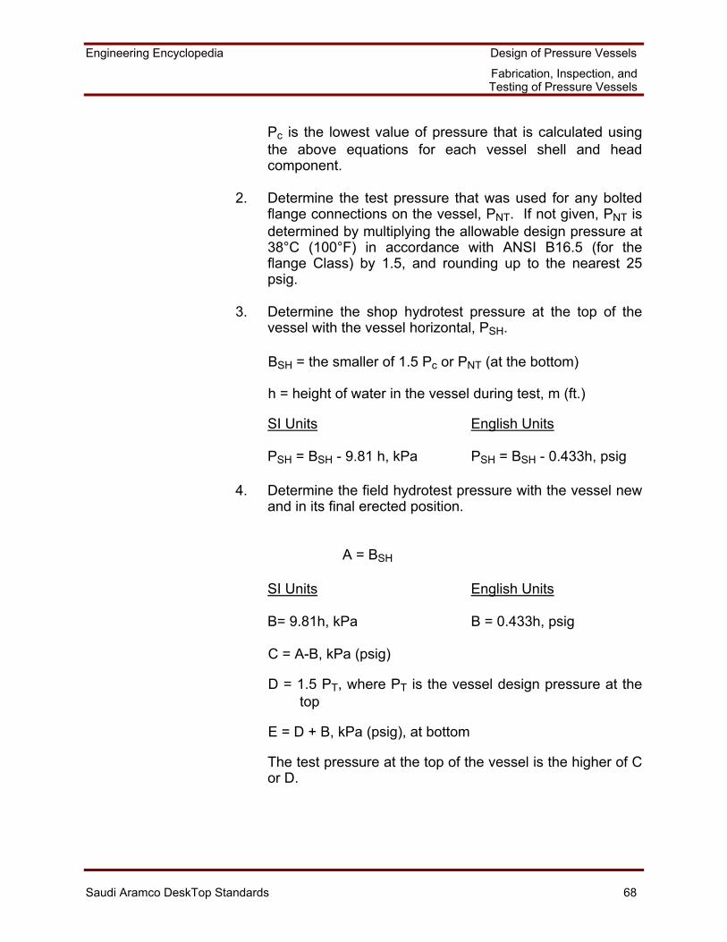
Engineering Encyclopedia Design of Pressure Vessels
Fabrication, Inspection, and Testing of Pressure Vessels
Saudi Aramco DeskTop Standards 68
Pc is the lowest value of pressure that is calculated using the above equations for each vessel shell and head component.
2. Determine the test pressure that was used for any bolted flange connections on the vessel, PNT. If not given, PNT is determined by multiplying the allowable design pressure at 38°C (100°F) in accordance with ANSI B16.5 (for the flange Class) by 1.5, and rounding up to the nearest 25 psig.
3. Determine the shop hydrotest pressure at the top of the vessel with the vessel horizontal, PSH.
BSH = the smaller of 1.5 Pc or PNT (at the bottom)
h = height of water in the vessel during test, m (ft.)
SI Units English Units
PSH = BSH - 9.81 h, kPa PSH = BSH - 0.433h, psig
4. Determine the field hydrotest pressure with the vessel new and in its final erected position.
A = BSH
SI Units English Units
B= 9.81h, kPa B = 0.433h, psig
C = A-B, kPa (psig)
D = 1.5 PT, where PT is the vessel design pressure at the top
E = D + B, kPa (psig), at bottom
The test pressure at the top of the vessel is the higher of C or D.
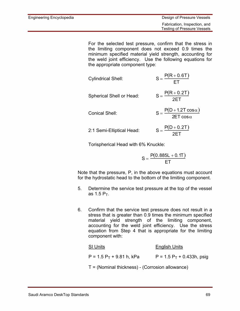
Engineering Encyclopedia Design of Pressure Vessels
Fabrication, Inspection, and Testing of Pressure Vessels
Saudi Aramco DeskTop Standards 69
For the selected test pressure, confirm that the stress in the limiting component does not exceed 0.9 times the minimum specified material yield strength, accounting for the weld joint efficiency. Use the following equations for the appropriate component type:
Cylindrical Shell: S =P R + 0.6T( )
ET
Spherical Shell or Head: S =P R + 0.2T( )
2ET
Conical Shell: S =P D +1.2T cosα( )
2ET cosα
2:1 Semi-Elliptical Head: S =P D + 0.2T( )
2ET
Torispherical Head with 6% Knuckle:
S =P 0.885L + 0.1T( )
ET
Note that the pressure, P, in the above equations must account for the hydrostatic head to the bottom of the limiting component.
5. Determine the service test pressure at the top of the vessel as 1.5 PT.
6. Confirm that the service test pressure does not result in a stress that is greater than 0.9 times the minimum specified material yield strength of the limiting component, accounting for the weld joint efficiency. Use the stress equation from Step 4 that is appropriate for the limiting component with:
SI Units English Units
P = 1.5 PT + 9.81 h, kPa P = 1.5 PT + 0.433h, psig
T = (Nominal thickness) - (Corrosion allowance)
Engineering Encyclopedia Design of Pressure Vessels
Fabrication, Inspection, and Testing of Pressure Vessels
Saudi Aramco DeskTop Standards 70
Note that "h" is the height of the water to the bottom of the limiting component.
7. Confirm that the requirements in SAES-A-004, Pressure Testing, are followed.
Work Aid 2C: Procedure for Hardness Test Plans
Use the checklist that follows to confirm that vessel vendor hardness test plans meet Saudi Aramco requirements. Saudi Aramco test requirements are specified in SAES-W-010, and 32-SAMSS-004, which are contained in Course Handout 2.
1. Vickers hardness testing of welding procedure qualification welds for sour service is required, with the following exceptions:
• Vessels fabricated of austenitic stainless steel or nickel-based alloys for all wetted pressure boundaries.
• All vessel internal surfaces that are clad or weld
overlaid with austenitic stainless steel or nickel-based alloys.
• Weld procedures are only for external structural
attachment welds, and the vessel wall at the attachment point is at least 25 mm (1.0 in.) thick.
2. Vickers hardness testing of welding procedure qualification
welds is required for any service if the wall thickness exceeds 38 mm (1.5 in.), except for:
• Vessels made from austenitic stainless steel or nickel-based alloys, or
• Welding procedure is used only for external structural
attachment welds.
3. Maximum allowable hardness for procedure qualification welds is VHN 250 when hardness testing is done.
Engineering Encyclopedia Design of Pressure Vessels
Fabrication, Inspection, and Testing of Pressure Vessels
Saudi Aramco DeskTop Standards 71
4. Brinell hardness testing of production welds is required for vessels of all materials that are in sour service.
• Maximum hardness of BHN 200 for P-No. 1 material (carbon steel)
• Maximum hardness per NACE MR-01-75, Sulfide
Stress Cracking Resistant Metallic Materials for Oilfield Equipment, for all other materials. Production weld hardness testing must meet API RP942, Controlling Weld Hardness of Carbon Steel Refinery Equipment to Prevent Environmental Cracking, and SAES-W-001 requirements.
5. Confirm that the vessel fabrication drawing or other vessel
documentation references SAES-W-010 for procedural requirements for hardness testing.
Work Aid 2D: Procedure for Impact Test Plans
Use the checklist that follows to confirm that vessel vendor impact test plans meet Saudi Aramco requirements. This checklist is applied after it has already been determined that the combination of material category, minimum design temperature, and thickness would not be exempt from impact testing in accordance with Section VIII, Division 2 criteria.
1. Confirm that fabrication drawings or other vessel documentation contains reference to the ASME Code Section VIII, Division 2 for impact test procedural requirements, even if the pressure vessel is designed in accordance with Division 1 in all other respects.
2. Impact test temperature is to be 18°C (32°F) below the minimum design temperature that is specified on the Pressure Vessel Design Data Sheet.
3. Confirm that reference is made to SAES-W-010 for other impact test requirements.
Engineering Encyclopedia Design of Pressure Vessels
Fabrication, Inspection, and Testing of Pressure Vessels
Saudi Aramco DeskTop Standards 72
GLOSSARY
capillary action The tendency of certain liquids to travel, climb, or draw
into tight crack-like interface areas due to such properties as surface tension, wetting, cohesion, adhesion, and viscosity.
communicating chamber An appurtenance to a vessel which intersects the shell or heads and forms an integral part of the pressure-containing enclosure.
crack A material separation that has a relatively large cross section in one direction and a small or negligible cross section when viewed in a direction perpendicular to the first direction.
defect A discontinuity whose size, shape, orientation, location, or properties make it detrimental to the useful service of the part in which it occurs; or a discontinuity which exceeds the accept/reject criteria of the particular design.
developer A finely divided material applied over the surface of a part to help bring out penetrant indications.
electrogas A modification of the flux-cored welding process in which there is an externally supplied source of gas or gas mixture.
electroslag A welding process in which consumable electrodes are fed into a joint containing flux; the current melts the flux, and the flux in turn melts the faces of the joint and the electrodes, allowing the weld metal to form a continuously cast ingot between the joint faces.
false indication An indication that may be interpreted incorrectly as a discontinuity or a defect; a nonrelevant indication.
ferritic Any magnetic iron alloy that contains more than 12% chromium and that has a body-centered cubic structure.
Engineering Encyclopedia Design of Pressure Vessels
Fabrication, Inspection, and Testing of Pressure Vessels
Saudi Aramco DeskTop Standards 73
flaw An imperfection which may not be harmful. (An imperfection that could be harmful is referred to as a defect or discontinuity.)
flux A coating of mineral compounds on a welding electrode that is intended to perform some function by chemical reactions in the weld pool.
flux lines Imaginary lines used to explain the behavior of magnetic fields.
heat-affected zone (HAZ) The portion of the base metal that is adjacent to the weld and that is affected by the welding heat.
inspection The process of examining and checking materials and parts for possible defects or deviation from acceptance standards.
lamination The arrangement of a solid in layers.
magnetic flux The total number of magnetic lines existing in a magnetic circuit.
nondestructive examination (NDE)
Testing to detect internal, surface, or concealed defects or flaws in a material by the use of techniques that do not damage the item being tested.
penetration The distance from the original surface of the base metal to that point at which weld fusion ends. The distance to which a projectile sinks into a target.
porosity The ability of a material to allow passage of a liquid. A material having porosity contains fine holes, voids, or pores.
Postweld Heat Treatment (PWHT)
A process that relieves residual stresses set up in welded joints after initial cooling.
radiography The use of radiant energy in the form of neutrons, x-rays, or gamma rays for NDE of opaque objects. The radiant energy produces graphical records on sensitized film; these records indicate the comparative soundness of the object being tested.
Engineering Encyclopedia Design of Pressure Vessels
Fabrication, Inspection, and Testing of Pressure Vessels
Saudi Aramco DeskTop Standards 74
slag The solidified, glassy mixture of impurities and flux that forms in the weld pool after chemical reaction.
shrinkage The contraction of either the base metal or weld metal upon cooling after the weld process.