fabrication of short polymer fibers by electrospinning … abstract polymer nanofibers are commonly...
TRANSCRIPT
Fabrication of Short Polymer Fibers by Electrospinning and Control
of Fiber Length
(静電紡糸法によるポリマー短繊維の合成および繊維長の制御)
By
Indra Wahyudhin Fathona
HIROSHIMA UNIVERSITY
SEPTEMBER 2014
Fabrication of Short Polymer Fibers by Electrospinning and Control
of Fiber Length
(静電紡糸法によるポリマー短繊維の合成および繊維長の制御)
A Dissertation Submitted to
The Department of Chemical Engineering
Graduate School of Engineering
Hiroshima University
By
Indra Wahyudhin Fathona
In Partial Fulfillment of the Requirement
For the Degree of
Doctor of Engineering
Hiroshima University
July 2014
Approved by
Professor Akihiro Yabuki
Advisor

i
Acknowledgement
First, I would like to express my praise and gratitude to Allah the almighty for
the gifts and blessings. I would like to express my sincere gratitude to Professor Akihiro
Yabuki for his guidance, support, and patience during my doctoral study. I also would
like to express my sincere gratitude to Professor Okuyama for all support since the
beginning to the end of my program. They also give me a precious chance to get
doctoral degree in Hiroshima University.
I wish thank to Professor Sakohara Syuuji and Professor Shiono Takeshi for
their patience, wisdom, and the valuable comments and suggestion. My grateful thank
also dedicated to Dr. Takashi Ogi and Dr. Toru Iwaki for their great support, advice, and
guidance during my research.
Special thanks are spent to Professor Khairurrijal, Professor Mikrajuddin
Abdullah, Dr. Ferry Iskandar, and Dr. Muhammad Miftahul Munir, Department of
Physics Institut Teknologi Bandung, for theirs never ending support on research
discussion and inspired spirit and work ethic, I am so proud to be theirs student and
collage. I also thanks to Dr. Asep Bayu Dani Nandiyanto, Dr. Asep Suhendi, and all
members of Thermal-Fluid Engineering Laboratory for theirs help and kindness in daily
life.
Thanks to Ministry of Education, Culture, Sports, Science and Technology
(MEXT) of japan for providing a doctoral scholarship, and Graduate School of
Engineering of Hiroshima University, Japan for organizing a doctoral course.
I would to thank to my beloved wife and daughter, to my parents, sister, and
brother for theirs support, pray, patience, motivation, and sacrifice. They give
immeasurable things into my life, and brought me happiness when I was down. Theirs
love give me a power and spirit to finish my study well.
Indra Wahyudhin Fathona
Higashi Hiroshima, July 2014

ii
Abstract
Polymer nanofibers are commonly fabricated by electrospinning methods for
application such as affinity membranes, filter media, and electrical application, etc.
Short polymer fibers have certain length, in which reliable as filler in composite
materials, drugs carrier, and material template. In this dissertation, two types of one-step
fabrication processes for short polymer fibers by electrospinning were developed, which
is used electric spark as cutting tool and is controlled electrospinning conditions. The
methodology to control the length of short polymer fibers was developed by altering a
needle inner diameter, applied voltage, flow rate of polymer solution, and added the
nanoparticles.
Chapter 1 provides an introduction and current progress of various methods to
fabricate polymer fibers, which are drawing method, template synthesis, phase
separation, self-assembly, and electrospinning.
Chapter 2 describes a development of one-step electrospinning process by
electric spark as a cutting tool to fabricate short electrospun polymer fibers. A solution
of cellulose acetate and organic solvent was ejected from a syringe needle and was
stretched by the electric field then it cut after passed through the gap between the tips of
two electrodes that generated an electric spark with frequency of 5 kHz. The obtained
short fibers have average length of 231 µm, and the theoretical calculation of fiber
length has been developed based on solution flow rate and electric spark frequency,
which fit with the experimental data.
Chapter 3 describes a simple one-step fabrication of short elcectrospun
polymer nanofibers with controllable length by manipulating polymer concentration,
flow rate, and applied voltage. The concentration of the cellulose acetate polymer in the
iii
solution was important factor which varied from 13 to 15 wt. %. The length of fibers
was increased by increasing the flow rate of the solution, and it was decreased with an
increase in applied voltage, resulting in controllable length of short nanofibers at 37 to
670 µm. The polymer solution jet ejected straight from the needle tip then it split and
segmented into short fiber because of the rapid increase of the repulsive force from
surface charges combined longitudinal forces from the applied voltage.
Chapter 4 describes the effect of inner diameter of a needle on the length of
electrospun polymer fibers. Cellulose acetate solution was ejected from various needles
with different inner diameter then it split and breaks into short polymer fibers by
electrostatic repulsion. The length could be controlled from 10 to 240 µm by increasing
the inner diameter of needle from 0.11 to 0.26 mm.
Chapter 5 describes the fabrication of short composite nanofibers of
TiO2/cellulose acetate. The length of the short composite nanofibers was significantly
decreased from 112 to 70 µm by the addition of 5 wt. % concentration of nanoparticles,
and it gradually continued to decrease as the nanoparticle concentration was increased
to 50 wt. %. The length of the short composite nanofibers with a low concentration of
nanoparticles was affected by the surface charge of the nanoparticles, and negatively
charged nanoparticles readily dispersed to the negatively charged polymers in solution,
which resulted in an elongation of the fabricated short composite nanofibers.
Chapter 6 describes a summary and some comments for further investigations.

Contents
iv
Contents
Acknowledgement ...................................................................................................... i
Abstract ......................................................................................................................... ii
Contents ....................................................................................................................... iv
List of Figures .......................................................................................................... viii
Chapter 1. Introduction ...........................................................................................1
1.1. Background .................................................................................................................1
1.2. Fabrication methods of short polymer fiber ...............................................................2
1.2.1. Drawing method ...............................................................................................3
1.2.2. Template synthesis method ..............................................................................3
1.2.3. Self-assembly method ......................................................................................4
1.2.4. Electrospinning method ...................................................................................4
1.3. Objectives and outline of dissertation ........................................................................6
1.4. References ..................................................................................................................9
Chapter 2. One-Step Fabrication of Short Electrospun Polymer Fiber
by Electric Spark ......................................................................................................14
2.1. Introduction ..............................................................................................................14

Contents
v
2.2. Experimental Methods ..............................................................................................17
2.2.1. Preparation of polymer solution .....................................................................17
2.2.2. Experimental setup .........................................................................................18
2.2.3. Observation of electric spark and frequency measurement ...........................20
2.2.4. Short electrospun polymer fiber observation .................................................21
2.3. Results and Discussion .............................................................................................21
2.3.1. Condition of electric spark .............................................................................21
2.3.2. Preparation of short electrospun polymer fiber ..............................................24
2.3.3. Cutting mechanism of short electrospun polymer fiber .................................27
2.4. Conclusions ..............................................................................................................31
2.5. References ................................................................................................................31
Chapter 3. A simple one-step fabrication of short polymer nanofibers
via electrospinning ...................................................................................................34
3.1. Introduction ..............................................................................................................34
3.2. Experimental methods ..............................................................................................37
3.2.1. Preparation of polymer solution .....................................................................37
3.2.2. Electrospinning of the polymer solution ........................................................37
3.2.3. Observation of electrospun fiber ....................................................................38
3.3. Results and Discussion .............................................................................................39
3.3.1. Effect of the polymer concentration in the polymer solution ........................39

Contents
vi
3.3.2. The effect of flow rate and voltage on fiber length of short nanofibers ........43
3.3.3. Mechanism for the formation of short nanofiber ...........................................47
3.5. Conclusions ..............................................................................................................51
3.6. References ................................................................................................................52
Chapter 4. One-step fabrication of short nanofibers by
electrospinning: effect of needle size on nanofiber length. ........................56
4.1. Introduction ..............................................................................................................56
4.2. Experimental .............................................................................................................57
4.2.1. Preparation and electrospinning of the polymer solution ..............................57
4.2.2. Observation of short nanofibers .....................................................................58
4.3. Results and Discussion .............................................................................................58
4.3.1. Effect of needle size on the fiber diameter and length ...................................58
4.3.2. Mechanism formation of short nanofibers .....................................................60
4.4. Conclusions ..............................................................................................................62
4.5. References ................................................................................................................62
Chapter 5. Short electrospun composite nanofibers: Effects of
nanoparticle concentration and surface charge on fiber length ..............64
5.1. Introduction ..............................................................................................................64
5.2. Experimental methods ..............................................................................................67
Contents
vii
5.2.1. Preparation of the polymer/nanoparticle solutions ........................................67
5.2.2. Electrospinning of the polymer/nanoparticle solutions .................................68
5.2.3. Measurement of the zeta potential of TiO2 nanoparticles ..............................68
5.2.4. Observation of short composite nanofibers ...................................................69
5.3. Results and discussion ..............................................................................................69
5.3.1. The effect of nanoparticle concentration on the length of short composite
nanofibers ......................................................................................................69
5.3.2. The effect of the zeta potential of nanoparticles on composite nanofiber
length .............................................................................................................73
5.3.3. Fabrication mechanism of short composite nanofibers ..................................76
5.4. Conclusions ..............................................................................................................79
5.5. References ................................................................................................................80
Chapter 6. Summary ...............................................................................................85

List of Figures
viii
List of Figures
Figure 2.1. Precursor solution of cellulose acetate.
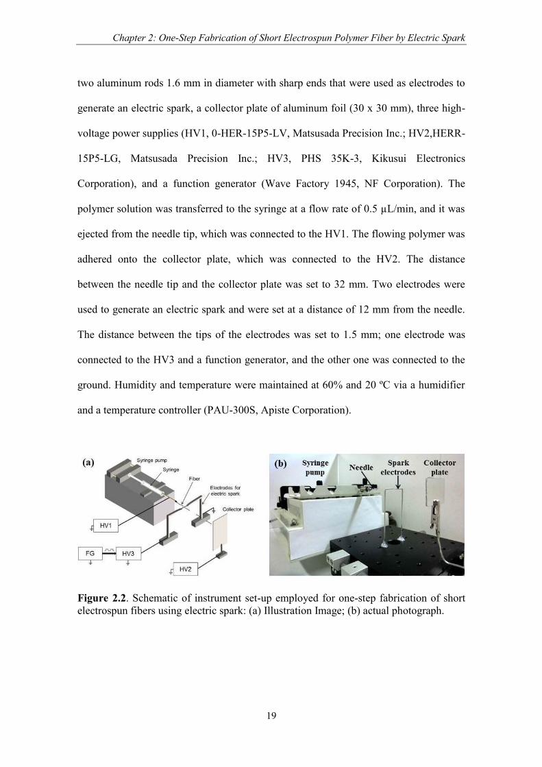
Figure 2.2. Schematic of instrument set-up employed for one-step fabrication of
short electrospun fibers using electric spark: (a) Illustration Image; (b)
actual photograph.
Figure 2.3. Condition of the typical electric spark occurred between the tips of two
electrodes. Electric spark was observed with a center diameter of
approximately 0.5 mm.
Figure 2.4. The typical sound wave generated by an electric spark at: (a) 3.6 kV; (b)
4.1 kV.
Figure 2.5. The typical sound wave of electric spark is recognized as damped
oscillation with frequency of 5 kHz. Observation is obtained from typical
sound wave at 4.1 kV by increasing the time resolution.
Figure 2.6. SEM images of (a) a short fiber, (b) the center of a short fiber, (c) the
edge of a short fiber, and (d) a continuous electrospun fiber without an
electric spark.
Figure 2.7. The distribution of the lengths of the short fibers.
Figure 2.8. The distribution of the diameters of the short fibers.
Figure 2.9. The conditions of electric sparks: (a) the electric spark was cutting the
fiber as the polymer solution was ejected; (b) the polymer solution was
not ejected.
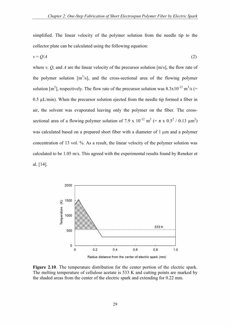
Figure 2.10. The temperature distribution for the center portion of the electric spark.
The melting temperature of cellulose acetate is 533 K and cutting points
List of Figures
ix
are marked by the shaded areas from the center of the electric spark and
extending for 0.22 mm.
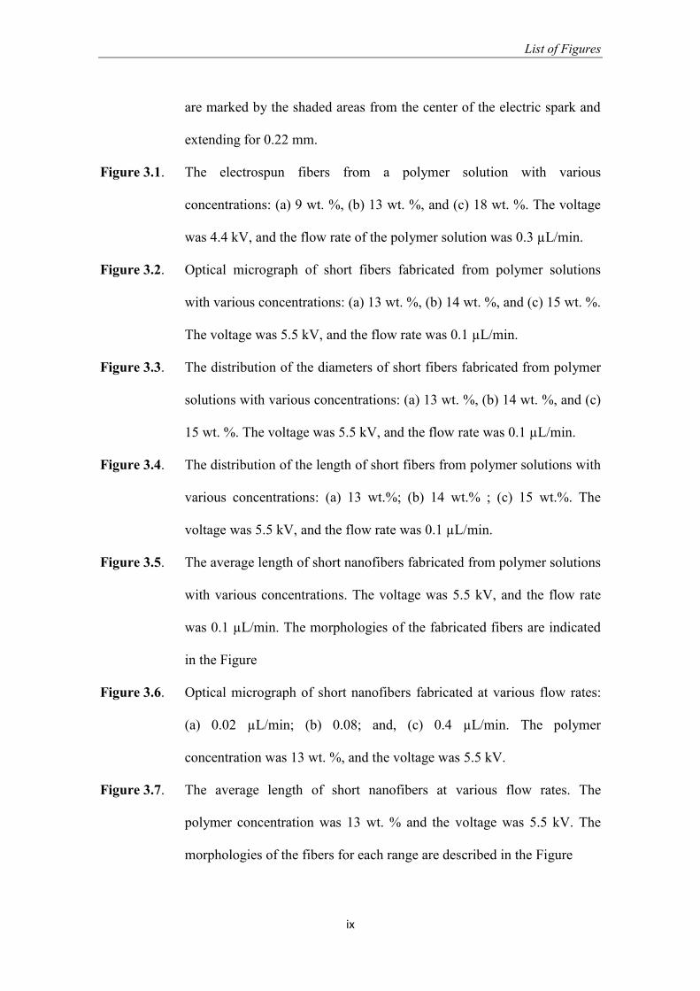
Figure 3.1. The electrospun fibers from a polymer solution with various
concentrations: (a) 9 wt. %, (b) 13 wt. %, and (c) 18 wt. %. The voltage
was 4.4 kV, and the flow rate of the polymer solution was 0.3 µL/min.
Figure 3.2. Optical micrograph of short fibers fabricated from polymer solutions
with various concentrations: (a) 13 wt. %, (b) 14 wt. %, and (c) 15 wt. %.
The voltage was 5.5 kV, and the flow rate was 0.1 µL/min.
Figure 3.3. The distribution of the diameters of short fibers fabricated from polymer
solutions with various concentrations: (a) 13 wt. %, (b) 14 wt. %, and (c)
15 wt. %. The voltage was 5.5 kV, and the flow rate was 0.1 µL/min.
Figure 3.4. The distribution of the length of short fibers from polymer solutions with
various concentrations: (a) 13 wt.%; (b) 14 wt.% ; (c) 15 wt.%. The
voltage was 5.5 kV, and the flow rate was 0.1 µL/min.
Figure 3.5. The average length of short nanofibers fabricated from polymer solutions
with various concentrations. The voltage was 5.5 kV, and the flow rate
was 0.1 µL/min. The morphologies of the fabricated fibers are indicated
in the Figure
Figure 3.6. Optical micrograph of short nanofibers fabricated at various flow rates:
(a) 0.02 µL/min; (b) 0.08; and, (c) 0.4 µL/min. The polymer
concentration was 13 wt. %, and the voltage was 5.5 kV.
Figure 3.7. The average length of short nanofibers at various flow rates. The
polymer concentration was 13 wt. % and the voltage was 5.5 kV. The
morphologies of the fibers for each range are described in the Figure
List of Figures
x
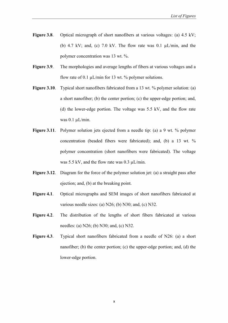
Figure 3.8. Optical micrograph of short nanofibers at various voltages: (a) 4.5 kV;
(b) 4.7 kV; and, (c) 7.0 kV. The flow rate was 0.1 µL/min, and the
polymer concentration was 13 wt. %.
Figure 3.9. The morphologies and average lengths of fibers at various voltages and a
flow rate of 0.1 µL/min for 13 wt. % polymer solutions.
Figure 3.10. Typical short nanofibers fabricated from a 13 wt. % polymer solution: (a)
a short nanofiber; (b) the center portion; (c) the upper-edge portion; and,
(d) the lower-edge portion. The voltage was 5.5 kV, and the flow rate
was 0.1 µL/min.
Figure 3.11. Polymer solution jets ejected from a needle tip: (a) a 9 wt. % polymer
concentration (beaded fibers were fabricated); and, (b) a 13 wt. %
polymer concentration (short nanofibers were fabricated). The voltage
was 5.5 kV, and the flow rate was 0.3 µL/min.
Figure 3.12. Diagram for the force of the polymer solution jet: (a) a straight pass after
ejection; and, (b) at the breaking point.
Figure 4.1. Optical micrographs and SEM images of short nanofibers fabricated at
various needle sizes: (a) N26; (b) N30; and, (c) N32.
Figure 4.2. The distribution of the lengths of short fibers fabricated at various
needles: (a) N26; (b) N30; and, (c) N32.
Figure 4.3. Typical short nanofibers fabricated from a needle of N26: (a) a short
nanofiber; (b) the center portion; (c) the upper-edge portion; and, (d) the
lower-edge portion.
List of Figures
xi
Figure 4.4. Diagram for the force of the polymer solution jet during the short
nanofiber fabrication: (a) a straight pass after ejection; and, (b) at the
breaking point.
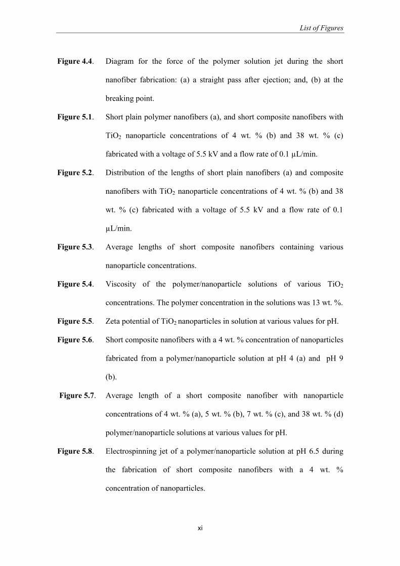
Figure 5.1. Short plain polymer nanofibers (a), and short composite nanofibers with
TiO2 nanoparticle concentrations of 4 wt. % (b) and 38 wt. % (c)
fabricated with a voltage of 5.5 kV and a flow rate of 0.1 µL/min.
Figure 5.2. Distribution of the lengths of short plain nanofibers (a) and composite
nanofibers with TiO2 nanoparticle concentrations of 4 wt. % (b) and 38
wt. % (c) fabricated with a voltage of 5.5 kV and a flow rate of 0.1
µL/min.
Figure 5.3. Average lengths of short composite nanofibers containing various
nanoparticle concentrations.
Figure 5.4. Viscosity of the polymer/nanoparticle solutions of various TiO2
concentrations. The polymer concentration in the solutions was 13 wt. %.
Figure 5.5. Zeta potential of TiO2 nanoparticles in solution at various values for pH.
Figure 5.6. Short composite nanofibers with a 4 wt. % concentration of nanoparticles
fabricated from a polymer/nanoparticle solution at pH 4 (a) and pH 9
(b).
Figure 5.7. Average length of a short composite nanofiber with nanoparticle
concentrations of 4 wt. % (a), 5 wt. % (b), 7 wt. % (c), and 38 wt. % (d)
polymer/nanoparticle solutions at various values for pH.
Figure 5.8. Electrospinning jet of a polymer/nanoparticle solution at pH 6.5 during
the fabrication of short composite nanofibers with a 4 wt. %
concentration of nanoparticles.
List of Figures
xii
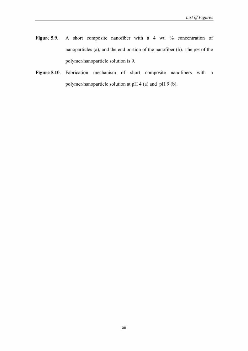
Figure 5.9. A short composite nanofiber with a 4 wt. % concentration of
nanoparticles (a), and the end portion of the nanofiber (b). The pH of the
polymer/nanoparticle solution is 9.
Figure 5.10. Fabrication mechanism of short composite nanofibers with a
polymer/nanoparticle solution at pH 4 (a) and pH 9 (b).
1
Chapter 1
Introduction
1.1. Background
Polymer fiber with diameter ranging from nanometer to micrometer is of great
interest because of their unique properties and has applications in many areas. They
have advantages and outstanding properties compared with their bulk size [1]. The term
of polymer micro-fiber is used to describe the polymer fiber with diameter ranging from
1-100 µm, whereas the term of nanofiber is used to describe the polymer fiber with a
diameter less than 1 µm. As the diameter of fiber shrunk from micrometer to nanometer,
the surface area to volume ratio of fiber was increased resulting in the changing on
physical properties [1]. Polymeric fibers can be produced with different morphologies
such as beaded fiber, short fiber, continuous fiber, and coaxial fiber morphologies in
which each has different applications. Therefore, control over the fiber morphology is
dispensable for their applications [2-6].
Several researchers have reported various morphologies of polymeric fibers,
such as beaded fibers, coaxial fiber, and short fibers [7-13]. Beaded fiber describes as a
continuous fiber with beads along its body. The occurrence of beads was causing the
lack of diameter uniformity. Beaded fiber can be fabricated by electrospinning by
altering the concentration of polymer in the precursor solution applied voltage, and
altering the additional ion on the precursor solution [7]. Coaxial fiber has a core-sheath
structure with core part consist of several channels and can be fabricated by
eletrsopinning method. This structure allows the formation of the hollow fiber and also
Chapter 1: Introduction
2
allows the encapsulation of several materials within the fiber [8]. Coaxial beaded fiber
has been applied as container of self-healing coating on the metal substrate [14].
Recently, short fiber fabrication has been a hot topic due to its wide applications
in the aerospace industry, automotive industry, corrosion protection, flexible display, etc.
[15-18]. Short fiber is a discrete fiber with lengths varied several nanometer to a few
millimeters. Short fiber fabrication can be done with one process or multiple processes.
In general, short-fiber fabrication is done by two processes, where the second process is
a process of cutting the continuous fiber into short fiber. The technique used is the
injection molding and extrusion in which the cutting is done mechanically with a knife
to make a short fiber [19-20]. Short fibers can also be made by electrospinning by using
mechanically and chemically cutting methods as a secondary process which performed
on continuous electrospun fiber to obtain short fiber [12,13]. However, the short fiber
fabrication by multiple processes has some deficiencies that cause the process becomes
inefficient and effective. Therefore, in this doctoral program, we are interesting in
developing a one-step process of short fiber fabrication by electrospinning.
In this dissertation, two types of one-step fabrication processes for short polymer
fibers by electrospinning were developed, which is used electric spark as cutting tool
and is controlled electrospinning conditions. The methodology to control the length of
short polymer fibers was developed by altering a needle inner diameter, applied voltage,
flow rate of polymer solution, and added the nanoparticles.
1.2. Fabrication methods of short polymer fiber
There are a number of techniques to fabricate short polymeric fiber, such as
drawing, template synthesis, self-assembly, and electrospinning, which resulted in the
Chapter 1: Introduction
3
polymer fiber with diameter varied from several nanometer to micrometer and length
varied from several nanometers to meters [21]. These short polymer fibers have been
applied as a sensor, drug delivery system, corrosion self-healing, membrane, etc.
1.2.1. Drawing method
The drawing method can produce fine fiber with diameter ranging from 2 to 100
nm and length ranging from 10 µm to several millimeters. Commonly, a sodium citrate
dissolve in chloroauric acid is use as a precursor solution. The milimetric droplet of
precursor solution is deposited on the surface and the fiber is fabricated by dipping a
micropipette into a milimetric droplet then withdrawn at speed of approximately 10-4
ms-1
[21]. The viscoelasticity of milimetric droplet is an important factor in drawing
method that can undergo strong deformation while being cohesive enough to support the
stress developed during the pulling. While using the polymer material as a precursor
solution, the length of obtained fiber were elongated due to the high molecular weight of
polymer materials increase viscoelasticity of the drawing solution [22,23]. The
advantage of drawing method is requiring minimum equipment, whereas the
disadvantage is discontinuous process. The length of short polymer fiber fabricated by
this method is depend on the viscoelasticity and viscosity of used polymer that correlate
with the tensile strength of polymer.
1.2.2. Template synthesis method
The template synthesis is a method to fabricate fiber by using a metal oxide
membrane as a template or mold. Commonly, nanoporous aluminum oxide is utilized as
a membrane. This method can fabricate fiber with length 10 µm and fiber diameter can
Chapter 1: Introduction
4
be adjusted by altering the pores sizes of membrane. The fibers are fabricate within the
single column chamber consist of water, polymer solution, membrane, and solidification
solution, which the solidification solution is separated from water and polymer solution
by aluminum oxide membrane. Pressurized water pushes the polymer solution into a
nanoporous membrane then the polymer fibers are come out from the nanoporous
membrane and solidified after contact with solidification solution. The advantage of this
method is the diameter of fiber can be adjusted by altering the template size [21,24].
1.2.3. Self-assembly method
The fabrication of short polymer fiber by self-assembly method is performed by
assembling the smaller molecules as building blocks into the nano-scale fiber. The
diameter of fiber is 7-100 nm and length varied from 1-20 µm [25-27]. The important
factor in fiber formation is intermolecular forces that caused the smaller units stick
together and the molecular shape that determine the shape of macromolecular shape.
This technique is feasible for fabrication of smaller polymeric fiber. However, it has
disadvantages such as take complex processes.
1.2.4. Electrospinning method
Electrospinning is the simplest and most reliable technique to fabricate polymer
fibers, which use high electric voltage. The conventional setup of electrospinning is
consist of a syringe with metal needle to hold the polymer solution, a syringe pump to
drain out the polymer solution through the tip of metal needle, a DC voltage power
supply in kV range, and grounded collector plate. High voltage is applied to a viscous
polymer solution in order to create an electrified polymer solution jet. The jet is
Chapter 1: Introduction
5
continuously stretched by electrostatic repulsions between the surface charges and the
solvent is evaporated leaving behind the polymer fiber [2].
Commonly, continuous fibers with diameter varied from 3 nm to 1 µm were
obtained by electrospinning method. The morphology of fiber such as smooth fiber and
beaded fiber is affected by polymer chain entanglement, which correlated directly with
polymer concentration in the solution. The polymer solution with chain entanglement
between 1 and 2.5 will produce beaded fiber, whereas polymer solution with chain
entanglement more than 2.5 will produce smooth and continuous fiber [28,29].
Electrospinning method also can fabricate coaxial fiber by utilizing coaxial needle or
single needle. Polymer/polymer or polymer/oil is utilized as an inner and outer solution
while the coaxial needle is used to fabricate coaxial fiber [30-33], whereas the emulsion
of polymer /polymer solution is used as precursor solution while the single needle is
used [33]. Composite polymer fiber is another type of fiber that can be produced by
electrospinning method. The precursor solution for electrospinning is a suspension of
polymer/nanoparticles [34-36].
Short polymer fiber can be fabricated by one-step process of electrospinning or
multiple processes. Luo et al reported the one-step fabrication of short fiber by
electrospinning [9]. The different molecular weight of polymethylsilsesquioxane
polymer were dissolve in the volatile solvent resulted in short microfiber with aspect
ratio varied from 10-200. The length of fiber was affected by molecular weight of
polymer therefore to control the length of fiber was not easy. The fabrication of short
polymer fiber by multiple processes including electrospinning is reported by several
researchers. Cutting process of continuous electrospun as a post processing is necessary
in order to obtain short fiber. A UV cutting method has been employed by Stoiljkovic

Chapter 1: Introduction
6
and Agarwal to produce 20-150 µm fibers [12]. They employed the concept of a
photocross-linking reaction upon UV radiation. The precursor for electrospinning was
double bound polymers with a photocross-linker and a photoinitiator. The electrospun
fibers were irradiated by UV in the presence of a mask slit, and, thus, the uncovered
fibers were cross-linked and insoluble, whereas the covered fibers were non-cross-
linked and soluble in the appropriate solvent. The short fibers were obtained by
immersing the irradiated fibers into the appropriate solvent. However, the length of the
fibers was limited by the width of the mask, and the process took more than one step.
Yoshikawa et al. reported the fabrication of shortened electrospun polymer fibers with a
well-defined concentrated polymer brush [13]. First, the electrospun fibers were
fabricated by electrospinning then the brush was formed on the surface of electrospun
fibers by atom transfer radical polymerization. The short fibers were obtained by cutting
the dispersed fibers in the water using homogenizer for 1 to 3h. The short fibers cut by
the Yoshikawa method were 11 µm in length and controllable by adjusting the cutting
time in the water. However, this technique requires several steps and much time for the
polymerization and cutting of the fibers. The current cutting methods are not entirely
convenient and require a relatively long amount of time due to the secondary process,
therefore a simple and straight-forward cutting method is necessary.
1.3. Objectives and outline of dissertation
The objective of this dissertation is to investigate the fabrication of short
polymer fibers by electrospinning and controlling electrospinning parameter in order to
obtain the controlled length of polymer fiber. Two types of one-step fabrication
processes for short polymer fibers by electrospinning were developed, which is used

Chapter 1: Introduction
7
electric spark as cutting tool and is controlled electrospinning conditions. The
methodology to control the length of short polymer fibers was developed by altering a
needle inner diameter, applied voltage, flow rate of polymer solution. The effect of
nanoparticles and theirs surface charge on the length of composite fiber were also
investigated. Cellulose acetate solution is used as precursor for short fiber fabrication.
The background and review of polymer fiber fabrication is describes in Chapter 1 and
outline of this dissertation is shown in Figure 1.
Chapter 2 describes a development of one-step electrospinning process by
electric spark as a cutting tool to fabricate short electrospun polymer fibers. A solution
of cellulose acetate and organic solvent was ejected from a syringe needle and was
stretched by the electric field then it cut after passed through the gap between the tips of
two electrodes that generated an electric spark with frequency of 5 kHz. The short fibers
were found on the collector plate with a density of 1-5 fibers per 0.12x0.2 mm2, whereas
the fibers that did not flow through to the electric spark were uncut and remained as
continuous fibers on the collector plate. The continuous fibers were dominant on the
collector plate due to the limited size of the cutting area of the electric spark: 1.5x0.5
mm2. The theoretical fiber length was calculated from the flow rate and the cross-
sectional area of the precursor polymer solution fibers, and the damped oscillation
frequency of the electric spark. The theoretical fiber length was calculated at 271 µm
when employing a 5 kHz of electric spark, which was in good agreement with the length
of the short fibers obtained in the experiment.
Chapter 3 describes the fabrication of elcectrospun short polymer nanofibers
with controllable length by manipulating polymer concentration and processing
parameters such as solution flow rate and voltage. The conventional electrospinning

Chapter 1: Introduction
8
setup is used and the production rate of short fiber is higher than that of electric spark
cutting method. The concentration of the cellulose acetate polymer in the solution was
important factor which varied from 13 to 15 wt. %. The length of fibers was increased
by increasing the flow rate of the solution, and it was decreased with an increase in
applied voltage, resulting in controllable length of short nanofibers at 37 to 670 µm. The
polymer solution jet ejected straight from the needle tip then it split and segmented into
short fiber because of the rapid increase of the repulsive force from surface charges
combined longitudinal forces from the applied voltage. The breaking of the fibers into
short nanofibers occurred because the repulsive force from the surface charges and the
longitudinal force from the applied voltage surpassed the tensile strength of the polymer
solution jet.
Figure 1. Dissertation outline
Chapter 1: Introduction
One –step fabrication using electric spark
Chapter 2: One-step fabrication of short electrospun polymer fiber by
electric spark
One-step fabrication by controlling electrospinning conditions
Chapter 3: A simple one-step fabrication of short polymer nanofibers viaelectrospinning
Chapter 4: One-step fabrication of short nanofibers by electrospinning:Effect of needle size on nanofiber length.
Fabrication of short composite fibers
Chapter 5: Short electrospun composite nanofibers: Effects of
nanoparticle concentration and surface charge on fiber length
Chapter 6: Summary

Chapter 1: Introduction
9
Chapter 4 describes a study of the needle inner diameter effect on the fiber
length. Cellulose acetate solution was ejected from various needles with different inner
diameter then it split and break into short polymer fibers by electrostatic repulsion. The
length of electrospun polymer fiber could be controlled from 10-240 µm by increasing
the inner diameter of needle from 0.11 to 0.26 mm.
Chapter 5 describes the fabrication of short composite nanofiber of
TiO2/cellulose acetate. The length of the short composite nanofibers was significantly
decreased from 112 to 70 µm by the addition of 5 wt. % concentration of nanoparticles,
and it gradually continued to decrease as the nanoparticle concentration was increased
to 50 wt. %. The length of the short composite nanofibers with a low concentration of
nanoparticles was affected by the surface charge of the nanoparticles, and negatively
charged nanoparticles readily dispersed to the negatively charged polymers in solution,
which resulted in an elongation of the fabricated short composite nanofibers.
In Chapter 6, the summary of all chapters is presented.
1.4. References
[1] Z.M. Huang, Y.Z. Zhang, M. Kotaki, S. Ramakrishna, A review on polymer
nanofiber by electrospinning and their applications in nanocomposites, Composites
Sci. Technol. 63 (2003) 2223-2253.
[2] D. Li, Y. Xia, Electrospinning of nanofibers: reinventing the wheel?, Adv. Mater 16
(2004) 1151-1170.
[3] H. Fong, I. Chun, D.H. Reneker, Beaded nanofiber form during electrospinning,
Polymer 40 (1999) 4585-4592.
Chapter 1: Introduction
10
[4] J.M. Deitzel, K.K. Meyer, D. Harris, N.C.B. Tan, The effect of processing variables
on the morphology of electrospun nanofibers and textiles, Polymer 42 (2001) 261-
272.
[5] H. Fong, W. Liu, C.S. Wang, R.A. Vaia, Generation of electrospun fibers of nylon 6
and nylon 6-montmorillonite nanocomposite, Polymer 43 (2002) 775- 780.
[6] M.G. McKee, G.L. Wilkes ,R.H. Colby, T.E. Long, Correlations of solution
rheology with electrospun fiber formation of linear and branched polyesters,
Macromol. 37 (2004) 1760-1767.
[7] K.H. Lee, H.Y. Kim, H.J. Bang, Y.H. Jung, SG Lee, The change of bead
morphology formed on electrospun polystyrene, Polymer 44 (2003) 4029-4034.
[8] Z. Sun, E. Zussman, A.L. Yarin, J.H. Wendorff and A. Greiner, Compound core–
shell polymer nanofibers by co-electrospinning, Adv. Mater. 15 (2003) 1929-1932.
[9] C.J. Luo, E. Stride, S. Stoyanov, E. Pelan, M. Edirisinghe, Electrospinning short
polymer micro-fibres with average aspect ratios in the range of 10-200, J Polym.
Res. 18 (2011) 2515-2522.
[10] I.W. Fathona, A. Yabuki, One-step fabrication of short electrospun fibers using an
electric spark, J. Mater. Proces. Technol. 213 (2013) 1894-1899.
[11] I.W. Fathona, A. Yabuki, A Simple One-Step Fabrication of Short Polymer
Nanofibers via Electrospinning, J. Mater. Sci. 49 (2014) 3519-3528.
[12] A. Stoiljkovic, S. Agarwal, Short electrospun fibers by UV cutting method,
Macromol. Mater. Eng. 293 (2008) 895-899.
[13] C. Yoshikawa, K. Zhang, E. Zawadzak, and H. Kobayashi, A novel shortened
electrospun nanofiber modified with a ‘concentrated’ polymer brush, Sci. Technol.
Adv. Mater. 12 (2011) 1-7.
Chapter 1: Introduction
11
[14] J.H. Park, P.V. Braun, Coaxial electrospinning of self-healing coating, Adv. Mater.
22 (2010) 496-499.
[15] L.N. Song, M. Xiao, X.H. Li, Y.Z. Meng, Short carbon fiber reinforced electrically
conductive aromatic polydisulfide/expanded graphite nanocomposites, Mater.
Chem. Phys. 93 (2005) 122-128.
[16] B. Yao, G. Wang, J. Ye, X. Li, Corrosion inhibition of carbon steel by polyaniline
nanofibers, Mater. Lett. 62 (2008) 1775-1778.
[17] S.A. Gordeyev, J.A. Ferreira, C.A. Bernardo, I.M. Ward, A promising conductive
material: highly oriented polypropylene filled with short vapour-grown carbon
fibres, Mater. Lett. 51 (2001) 32.
[18] E. Hablot, R. Matadi, S. Ahzi, L. Averous, Renewable biocomposites of dimer
fatty acid-based polyamides with cellulose fibres: Thermal, physical and
mechanical properties, Compos. Sci. Technol. 70 (2010) 504-509.
[19] S.Y. Fu, B. Lauke, E. Mader, X. Hu, C.Y. Yue, Fracture resistance of short-glass-
fiber-reinforced and short-carbon-fiber-reinforced polypropylene under Charpy
impact load and its dependence on processing. Journal of Materials Processing
Technology 89-90 (1999) 501-507.
[20] S.Y. Fu, B. Lauke, E. Mader, C.Y. Yue, X. Hu, Tensile properties of short-glass-
fiber and short-carbon-fiber-reinforced polypropylene composites. Composites:
Part A 31 (2000) 1117-1125.
[21] S. Ramakrishna, F. Kazutoshi, T. Wee-Eong, L. Teik-Cheng, M. Zuwei, An
introcduction to electrospinning and nanofibers, World Scientific Publishing Co.
Pte. Ltd. (2005) 7-21.

Chapter 1: Introduction
12
[22] S.N. Amrinder, C.W. Joanna, A. Cristina, S. Metin, Drawing suspended polymer
micro-/nanofibers using glass micropipettes, Appl. Phys. Lett. 89 (2006) 183105-
18308.
[23] X. Xiaobo, W. Yuqing, L. Baojun, Nanofiber drawing and nanodevice assembly in
poly (trimethylene terephthalate), Optics express, 16 (2008) 10815-10822.
[24] F. Lin, L. Shuhong, L. Huanjun, Z. Jin, S. Yanlin, J. Lei, Z. Daoben, Super-
hydrophobic surface of aligned polyacrilonitrile nanofibers, Angew Chem. Int. Ed.
41 (2002) 1221-1223.
[25] T.G James, T. Hashimoto, K. Saijo, Polystyrene-block-poly(2-cinnamoylethyl
methacrylate) nanofibers preparation, characterization, and liquid crystalline
properties, Chem. Eur. J. 5 (1999) 2740-2749.
[26] G. Liu, L. Qiao, A. Guo, Diblock copolymer nanofibers, Macromolecules 29
(1996) 5508-5510.
[27] K. de Moel, G. O. R. A. Ekenstein, H. Nijland, E. Polushkin, G. ten Brinke,
Polymeric Nanofibers prepared from self-organized supramolecules, Chem. Mater.
13 (2001) 4580 – 4583.
[28] M.M. Munir, A.B. Suryamas, F. Iskandar, K. Okuyama, Scaling law on particle-to-
fiber formation during electrospinning, Polymer 50 (2009) 4935–4943.
[29] S.L. Shenoy, W. D. Bates, H.L. Frisch, G.E. Wnek, Role of chain entanglements on
fiber formation during electrospinning of polymer solutions: good solvent, non-
specific polymer–polymer interaction limit, Polymer 46 (2005) 3372–3384.
[30] D. Li, Y. Xia, Direct fabrication of composite and ceramic hollow nanofibers by
electrospinning, Nano Lett. 4 (2004) 933–938.

Chapter 1: Introduction
13
[31] X. Li, Q. Qian, W. Zheng, W. Wei, X. Liu, L. Xiao, Q. Chen, Y. Chen, F. Wang,
Preparation and characteristics of LaOCl nanotubes by coaxial electrospinning,
Mater. Lett. 80, (2012) 43-45.
[32] D. Han, A.J. Steckl, Superhydrophobic and oleophobic fibers by coaxial
electrospinning, Langmuir 25 (2009) 9454–9462.
[33] A.L.Yarin, Coaxial electrospinning and emulsion electrospinning of core–shell
fibers, Polym. Adv. Technol. (2011) 22 310–317.
[34] L.D. Tijing, A. Amarjargal, Z. Jiang, M.T.G. Ruelo, C.H. Park, H.R. Pant, D.W.
Kim, D.H. Lee, C.S. Kim, Antibacterial tourmaline nanoparticles/polyurethane
hybrid mat decorated with silver nanoparticles prepared by electrospinning and UV
photoreduction, Curr. Appl. Phys. 13 (2013) 205-210.
[35] N.A.M. Barakat, M.F. Abadir, F.A. Sheikh, M.A. Kanjwal, S. J. Park, H.Y. Kim,
Polymeric nanofibers containing solid nanoparticles prepared by electrospinning
and their applications, Chem. Eng. 156 (2010) 487-495.
[36] D.P. Macwan, P.N. Dave, S. Chaturvedi, A review on nano-TiO2 sol–gel type
syntheses and its applications, J. Mater. Sci. 46 (2011) 3669–3686.

14
Chapter 2
One-step fabrication of short electrospun polymer fiber by electric
spark
2.1. Introduction
The short fiber fabrication process has been drawn a tremendous attention of
many researchers due to the broad applications of short fibers, which varied from
mechanical engineering to corrosion protection. Short fibers were applied as filler or
reinforcement to improve the electrochemical, thermal properties, and mechanical of
polymer matrix. Fu et. al reported that short carbon fibers and short glass fibers
reinforced to the polymer matrix have enhanced the tensile properties [1,2]. This
composite is applicable for aerospace and automotive industries, due to its lightweight
and excellent mechanical properties. In corrosion protection field, adding the
polyanilinne (PANI) short fibers into the coating process of carbon steel (CS) has
enhanced the corrosion resistance of coated carbon steel [3]. The thermomechanical
stability of poly (butylene succianate) has greatly improved by introducing
biodegradable reinforcement of short silk fiber [4]. This performance improvement of
an environmentally friendly material makes biocomposites industrially applicable.
Recently, the process of short fibers fabrication usually involved the mechanical,
thermal, and polymerization processes. These processes are responsible for the
formation of the short fibers. Each process has yielded short fibers that range in size
from millimeters to nanometers and each has several drawbacks. Yao et al. [3] has used
Interfacial polymerization to fabricate PANI short fibers ranging from 200-400 nm. The
monomers of aniline were dissolved in chloroform then the interfacial

Chapter 2: One-Step Fabrication of Short Electrospun Polymer Fiber by Electric Spark
15
polymerization was conducting in a mixture of HCl and ammonium persulfate solution.
This process is expensive and environmentally harmful due to the use of an acid
chloride reactant and a toxic solvent. Fu et al. [1] have been employed Extrusion
compounding and injection molding processes in order to fabricate short-glass-fiber and
short-carbon-fiber reinforcement with length ranging from 150-300 µm. The glass and
carbon roving fibers were melted at 214-239 oC using a twin-screw extruder then the
cooled extruded strands were chopped mechanically to form short fibers. In order to
form a composite polymer bulk, these short fibers were injection-molded with
polypropylene at 210-230 oC forming a dumbbell-shaped composite. The high
temperature and many-staged processes reduce the cost-effectiveness of this method.
These problems have encouraged many researchers to seek effective process for the
fabrication of short fibers.
The effective method to fabricate short fiber have been performed and developed.
The research has focused on electrospinning-based fabrication due to its wide
application, and due to the simple process and efficient for the fabrication of polymer
composite nanofibers [5] and ceramic nanofibers [6]. The electrospinning technique
utilizes a high voltage, which applied to a viscous polymer solution in order to create an
electrified jet. The surface charges were generated on the solution and then it
continuously stretched by electrostatic repulsions between the surface charges and the
evaporation solvents, forming polymer fibers [5]. Generally, electrospinning technique
fabricates continuous fibers therefore cutting process is necessary to obtain short fibers.
A photocross-linking under influence of UV-radiation has been employed as a cutting
method by Stoiljkovic and Agarwal [7] in order to produce 20-150 µm short fibers.
They employed the concept of a polymer chain photocross-linking reaction upon UV

Chapter 2: One-Step Fabrication of Short Electrospun Polymer Fiber by Electric Spark
16
radiation. The solution precursor for electrospinning was double-bound polymers
solution including a photocross-linker and a photoinitiator. The obtained electrospun
fibers were irradiated by UV in the presence of a mask slit. The uncovered electrospun
fibers were cross-linked and insoluble, whereas the covered fibers were non-cross-
linked and soluble in the appropriate solvent. The short fibers were obtained by
immersing the irradiated fibers into the appropriate solvent. However, the length of the
fibers was limited by the width of the mask, and the process took more than one-step.
Yoshikawa et al. [8] reported the fabrication of shortened electrospun polymer fibers
with a well-defined concentrated polymer brush. This method was dividing into three
major processes, which are electrospinning of continuous fiber, brush-like formation,
and mechanical cutting. The first process was electrospinning of polymer solution to
fabricate continuous fiber. The second process was the brush formation on the surface
of continuous electrospun fibers using atom transfer radical polymerization method. The
last process was the cutting process of these continuous fibers in the water using
homogenizer for 1 to 3h. The short fibers were 11µm in length and controllable by
adjusting the cutting time in the water. However, this technique requires several steps
and much time for the polymerization and cutting of the fibers. The current cutting
methods are not entirely convenient and require a relatively long amount of time due to
the secondary process; therefore, a simple and straightforward cutting method is
necessary.
The cutting technique via an electric spark established in electrical discharge
machining (EDM) can be applied to the fabrication of short fibers. EDM is well-known
method to cutting and material machining process via an electric spark. This method is a
machining process for the manufacturing of geometrically complex and hard material
Chapter 2: One-Step Fabrication of Short Electrospun Polymer Fiber by Electric Spark
17
parts. The thermal energy of the electric spark initializes a substantial amount of heating
and melts the material on the surface of solid metal [9]. The electric spark can be simply
generated between the tips of two electrodes by applying a high voltage to one of them
and by keeping the other one at ground level. The occurrence of electric spark is
dependent on the amplitude of the electric field and on the distance between the tips of
the two electrodes [10].
In this Chapter, a one-step process for the production of short polymer fibers
using an electrospinning technique and periodic electric spark was proposed. Different
from the current electrospinning-based techniques, the cutting process was conducted in
situ by electric spark during electrospinning of polymer precursor. A single step and
relatively simple and low cost process could be achieved using this method. The electric
spark was generated by adjusting the distance between the tips of two electrodes, then
applying a voltage to the electrodes. A biodegradable polymer of cellulose acetate was
employed. A solution of cellulose acetate and organic solvent was ejected from a
syringe needle and was stretched by the electric field then it cut after passed through the
gap between the tips of two electrodes that generated an electric spark with frequency of
5 kHz. The lengths and diameters of the obtained short electrospun polymer fibers are
characterized herein, as well as the cutting mechanism used to obtain the short
electrospun polymer fibers.
2.2. Experimental methods
2.2.1. Preparation of polymer solution
Cellulose acetate (CA, Sigma Aldrich, UK) with a molecular weight (Mw) of
30,000 was used. The solvent was a mixture of acetone (99.5% of purity, Kanto

Chapter 2: One-Step Fabrication of Short Electrospun Polymer Fiber by Electric Spark
18
Chemical, Japan) and N,N-dimethyl formamide (DMF) (99.5% of purity, Wako
Chemical, Japan ) at a volume ratio of 2:1. DMF was mixed with acetone in order to
delay the evaporation of acetone during electrospinning [11]. The total volume fraction
of CA in the solution was set at 13 vol %. The polymer solution for electrospinning was
prepared by pouring the CA powder into a glass bottle containing solvent. The mixture
of CA and solvent in the closed bottle was then stirred using a magnetic stirrer for
several hours until a homogenous solution was obtained (Figure 2.1).
Figure 2.1. Precursor solution of cellulose acetate.
2.2.2. Experimental setup
A schematic of the apparatus and an actual photograph used to electrospin and
cut the polymer fibers is shown in Figures 2.2a and b, respectively. The apparatus
consisted of a micro syringe pump (ESP64, EiCom Corporation), a 1,000 cc syringe
(TTL 2-432, Hamilton Company) with a stainless needle (OD: 0.8 mm, ID: 0.5 mm),
Chapter 2: One-Step Fabrication of Short Electrospun Polymer Fiber by Electric Spark
19
two aluminum rods 1.6 mm in diameter with sharp ends that were used as electrodes to
generate an electric spark, a collector plate of aluminum foil (30 x 30 mm), three high-
voltage power supplies (HV1, 0-HER-15P5-LV, Matsusada Precision Inc.; HV2,HERR-
15P5-LG, Matsusada Precision Inc.; HV3, PHS 35K-3, Kikusui Electronics
Corporation), and a function generator (Wave Factory 1945, NF Corporation). The
polymer solution was transferred to the syringe at a flow rate of 0.5 µL/min, and it was
ejected from the needle tip, which was connected to the HV1. The flowing polymer was
adhered onto the collector plate, which was connected to the HV2. The distance
between the needle tip and the collector plate was set to 32 mm. Two electrodes were
used to generate an electric spark and were set at a distance of 12 mm from the needle.
The distance between the tips of the electrodes was set to 1.5 mm; one electrode was
connected to the HV3 and a function generator, and the other one was connected to the
ground. Humidity and temperature were maintained at 60% and 20 ºC via a humidifier
and a temperature controller (PAU-300S, Apiste Corporation).
Figure 2.2. Schematic of instrument set-up employed for one-step fabrication of short
electrospun fibers using electric spark: (a) Illustration Image; (b) actual photograph.
Chapter 2: One-Step Fabrication of Short Electrospun Polymer Fiber by Electric Spark
20
2.2.3. Observation of electric spark and frequency measurement
The generation of an electric spark by the tips of the two electrodes was
observed using a CCD camera with a resolution of 0.4 MP, twice-digital zoom, and 0.8
lux of minimum illumination (MTV-73x11HN, Mintron Enterprise Co., Ltd). A
monocular optical lens with a diameter of 50 mm and a magnification factor of 8
(M0850, Specwell) was attached to the CCD camera. The images were taken at a speed
of 30 fps and were recorded on a personal computer (PC). The condition of the electric
spark when a polymer solution was flowed between the tips of the two electrodes was
also observed. The CCD camera was placed above the two electrodes to capture the
electric spark. The PC recorded these conditions for 2 min, and still images were cut
from the video that was produced.
The frequency of the electric spark was analyzed from a beat sound that
occurred during the electric spark. When the electric spark occurred, an electric current
transient went through the spark channel and produced an intense release of heat. This
rapid thermal change caused a sharp rise in pressure, which generated a beat sound due
to the sonic waves [12]. The sound was recorded as a waveform on the PC through
audio analyzer software (Audacity 1.3 Beta) and a microphone for 50 s with a sampling
rate of 44 ksps. The waveform was plotted and analyzed in the time domain using the
same audio analyzer software to find peaks showing the beat sounds. The peaks images
in different time resolutions (Figures 2.4 and 2.5) were printed on the screen, then the
time interval between the peaks were measured by image processing software (Ruler ver.
0.002) to obtain the frequency of the electric spark. During the spark measurement, the
values for temperature and humidity were maintained under the same conditions as
those of electrospinning.
Chapter 2: One-Step Fabrication of Short Electrospun Polymer Fiber by Electric Spark
21
2.2.4. Short electrospun polymer fiber observation
The prepared short fibers were observed by SEM (JSM-6340F, JEOL Ltd.) with
a maximum magnification factor of 650,000x and a resolution of 1.2 nm at an
acceleration voltage of 20 kV. The shape of the short fibers was evaluated by measuring
the diameter at the centers and the edges of the fibers, which were also compared with
those of the continuous electrospun polymer fibers.
The distribution of the lengths of the short electrospun polymer fibers was
measured using the ruler function of image processing software during observation
using a digital microscope with a resolution of 2.11 MP (VH-8000, Keyence
Corporation) and a high-range zoom lens with a magnification ranging from 450 -
3,000x (VH-Z450, Keyence Corporation). The distribution of the diameters of the
center parts of the short fibers was noted. The mean length and diameter of the short
fibers was calculated from the measurement of approximately 200 fibers.
2.3. Results and discussion
2.3.1. Condition of electric spark
Figure 2.3 shows the typical electric spark generated within a spark gap. A
bluish-white electric spark was observed with a center diameter of approximately 0.5
mm. To generate electric spark, sufficient voltage was generated within the spark gap.
In this experiment, the electrodes had sharp ends and the breakdown voltage of the
electric spark was found at 3.5 kV with a spark gap of 1.5 mm. Compared to the
spherical electrodes, the electrodes with sharp ends gave a lower voltage breakdown for
the generation of electric spark [12]. Due to the distance ratio of the spark gap and the

Chapter 2: One-Step Fabrication of Short Electrospun Polymer Fiber by Electric Spark
22
needle-collector (1:21), the electric field generated between the needle and the collector
was found to have not significantly affected the electric spark.
Figure 2.3. Condition of the typical electric spark occurred between the tips of two
electrodes. Electric spark was observed with a center diameter of approximately 0.5
mm.
The characteristics of an electric spark were investigated by detecting and
recording the sound waves produced by an electric spark. Two voltages, 3.6 and 4.1 kV,
were applied to investigate the characteristics of a typical sound wave. Figures 2.4a and
b show a typical sound wave over a 1 sec period generated at both voltages, respectively.
There were 18 and 33 spikes at voltages of 3.6 and 4.1 kV, respectively. As the time
resolution for Figures 2.4a and b was increased, each spike at both voltages was
recognized as damped oscillation with a frequency of 5 kHz (Figure 2.5). These results
confirm that the typical sound wave of an electrical spark has a damped oscillation with
a repetitive occurrence. The occurrence interval of a damped oscillation was more
uniform at 4.1 kV than it was at 3.6 kV. Due to the occurrence interval of the damped
oscillation, the electric spark generated at 4.1 kV was reliable for the fabrication of short
fibers.

Chapter 2: One-Step Fabrication of Short Electrospun Polymer Fiber by Electric Spark
23
Figure 2.4. The typical sound wave generated by an electric spark at: (a) 3.6 kV; (b) 4.1
kV
Figure 2.5. The typical sound wave of electric spark is recognized as damped
oscillation with frequency of 5 kHz. Observation is obtained from typical sound wave at
4.1 kV by increasing the time resolution.

Chapter 2: One-Step Fabrication of Short Electrospun Polymer Fiber by Electric Spark
24
2.3.2. Preparation of short electrospun polymer fiber
The short fibers were prepared by electrospinning that included an electric spark
to cut the fibers. A polymer solution was ejected from a syringe into the collector and
partially through the electric spark gap. The fibers that flowed through to the electric
spark gap were cut and short fibers were found on the collector plate with a density of 1-
5 fibers per 0.12x0.2 mm2, whereas the fibers that did not flow through to the electric
spark were uncut and remained as continuous fibers on the collector plate. The
continuous fibers were dominant on the collector plate due to the limited size of the
cutting area of the electric spark: 1.5x0.5 mm2
(Figure 2.3). For comparison, the
continuous fibers were also prepared by a common electrospinning set up. A
comparison of the diameters of short fibers and continuous fibers was performed to
study the influence of electric spark on fiber fabrication.
Figure 2.6 shows the SEM images of prepared short fiber and continuous fibers
produced by the method outlined in this chapter and by common electrospinning,
respectively. The length of the short fiber was approximately 100 µm, and one edge was
curled (Figure 2.6a). The rectangle boxes in Figure 2.6a are magnifications of the
center and the edge parts of the short fiber that show the diversity in diameter. The
diameters at the center part ranged from 500 to 1000 nm (Figure 2.6b). The edge of the
short fiber was not smooth (Figure 2.6c), and the diameters varied from 200 to 140 nm,
which was narrower than that of the center part of the short fiber. From the observation
of the shape of the short fiber, it seems apparent that the electrospun fiber was stretched
and cut by the periodic electrical field and thermal energy from the electric spark,
respectively.

Chapter 2: One-Step Fabrication of Short Electrospun Polymer Fiber by Electric Spark
25
Figure 2.6. SEM images of (a) a short fiber, (b) the center of a short fiber, (c) the edge
of a short fiber, and (d) a continuous electrospun fiber without an electric spark.
The diameters of continuous electrospun fibers produced by common
electrospinning (Figure 2.6d) varied from 90 to 400 nm. Compared with the diameters
of the short fibers, the diameters at the edges of the short fibers were smaller than those
of the continuous fibers, and the diameters at the centers of the short fibers were larger
than those of the continuous fibers. This indicated that the short electrospun fibers were
not only stretched but were also compressed. The electric field generated by the electric
spark blocked the fiber flow, so that it compressed the mass in the centers of the short
fibers.
Figure 2.7 shows the distribution of the lengths of the short electrospun fibers,
which were measured by optical microscope. The lengths varied from 22 to 1,000 µm.
Most of the short fibers prepared in the experiment ranged from 22 to 400 µm in length,
although a small amount of the fibers had lengths ranging from 500 to 1,000 µm. This
result confirmed that short fibers were fabricated although the continuous fiber was still

Chapter 2: One-Step Fabrication of Short Electrospun Polymer Fiber by Electric Spark
26
observed. The mean length of the short fibers was 230 µm. Figure 2.8 shows the
distribution of the diameters for the centers of the short fibers. The diameters primarily
ranged from 0.6 to 1.4 µm. The mean diameter of the short fibers was 1 µm.
Figure 2.7. The distribution of the lengths of the short fibers.
Figure 2.8. The distribution of the diameters of the short fibers.

Chapter 2: One-Step Fabrication of Short Electrospun Polymer Fiber by Electric Spark
27
2.3.3. Cutting mechanism of short electrospun polymer fiber
In order to confirm the mechanism of fiber cutting, the video and images around
the electric spark gap were captured and recorded on a PC. The fiber motion in
electrospinning was random, however, in this experiment the fibers had passed the spark
gap and the image was captured successfully. As the polymer solution was ejected, the
spark cut the fiber. Truncated fibers were on the left and the right sides of the electric
spark (Figure 2.9a). As the electric spark cut the fiber, it had a wide shape with a
bluish-white color in the center and a red color on the left and the right sides. For
comparison, the condition of the electric spark without a polymer solution ejected from
the needle was obtained (Figure 2.9b). The electric spark had a straight and slim shape
with a bluish-white color. These results confirmed that fiber flowed toward the spark
gap then the electric spark burned and truncated it in one particular spot.
Figure 2.9. The conditions of electric sparks: (a) the electric spark was cutting the fiber
as the polymer solution was ejected; (b) the polymer solution was not ejected.
For further analysis, the temperature distribution of the steady-state condition
around an electrical spark was also estimated. Based on the temperature distribution, the
cutting points were estimated. The temperature distribution along the x-y axis was
derived as follows:
Chapter 2: One-Step Fabrication of Short Electrospun Polymer Fiber by Electric Spark
28
t
Tcq
y
T
yx
T
xyx
(1)
Eq. (1) can be solved numerically using a 2D finite element method (Quickfield, Tera
Analysis Ltd.), where x and y are components of the heat conductivity tensor on the x-
y axis [W/K.m], T is the temperature [K], q is the volume power of the heat source
[W/m3], c is the specific heat of air [J/kg.K], and is the density of air [kg/m
3]. The
initial ambient temperature is set at 293 K and the melting point of cellulose acetate is
533 K (Material Safety Data Sheet). Electric spark power was calculated from the data
of voltage applied and the electric current (V=4.1 kV, I=0.8 mA). It was assumed that
electric spark has a cylindrical shape with a cross-sectional diameter and height that are
0.5 mm and 1.5 mm, respectively. The volume power of the heat source was obtained
by dividing the electric spark power by the volume of the electric spark to yield
1.1x10¹⁰
W/m3. For analysis simplicity, the volume power of the heat source was
assumed to be constant over the time. Figure 2.10 shows the temperature distribution
for a 1 mm radius with respect to the center of the electric spark. The results confirmed
that cutting points lie in a radial direction from the center of a spark up to 0.22 mm
(shaded area in Figure 2.10). These results also confirmed that high temperatures of an
electric spark are distributed within the electric spark in a radius of less than 0.5 mm.
This result agreed with that found by Zeng and Zhao [13].
With regard to the cutting of an electrospun fiber by an electric spark, the length
of a short electrospun fiber should be related to the linear velocity of the polymer
solution and to the frequency of the electric sparks. We considered that only the fibers
with linear motion were cut by an electric spark, therefore the calculation could be
Chapter 2: One-Step Fabrication of Short Electrospun Polymer Fiber by Electric Spark
29
simplified. The linear velocity of the polymer solution from the needle tip to the
collector plate can be calculated using the following equation:
v = Q/A (2)
where v, Q, and A are the linear velocity of the precursor solution [m/s], the flow rate of
the polymer solution [m3/s], and the cross-sectional area of the flowing polymer
solution [m2], respectively. The flow rate of the precursor solution was 8.3x10
-12 m
3/s (=
0.5 µL/min). When the precursor solution ejected from the needle tip formed a fiber in
air, the solvent was evaporated leaving only the polymer on the fiber. The cross-
sectional area of a flowing polymer solution of 7.9 x 10⁻¹²
m2 (= π x 0.5
2 / 0.13 µm
2)
was calculated based on a prepared short fiber with a diameter of 1 m and a polymer
concentration of 13 vol. %. As a result, the linear velocity of the polymer solution was
calculated to be 1.05 m/s. This agreed with the experimental results found by Reneker et
al. [14].
Figure 2.10. The temperature distribution for the center portion of the electric spark.
The melting temperature of cellulose acetate is 533 K and cutting points are marked by
the shaded areas from the center of the electric spark and extending for 0.22 mm.

Chapter 2: One-Step Fabrication of Short Electrospun Polymer Fiber by Electric Spark
30
The length of the short electrospun fiber was predicted by dividing the linear
velocity of the polymer solution by the frequency of the damped oscillation of the
electric spark, as follows:
l = v/f = Q/Af (3)
where l and f are the length of the short electrospun fiber [m] and the frequency of the
electric spark [Hz], respectively. The fiber length calculated from 5 kHz was 271 µm.
This calculation approximated the measured fiber length of 230 µm, thus confirming
that the cutting to prepare a short fiber was due to an electric spark of 5 kHz. The
dispersion of the distribution of the lengths of the short fibers shown in Figure 2.7 was
caused by a fluctuation in the flow rate of the polymer solution, by different cutting
points, and by the dumped oscillation of an electric spark. There were 5-7 peaks in the
damped oscillation of 5 kHz with decaying amplitude, as shown in Figure 2.5. We
suspected that some peaks did not cut the fibers, so that short fibers with lengths of 400-
1,000 µm were created. We suspected that the variation of the cutting point in a radial
direction also affected the distribution of the lengths of prepared short fibers.
In order to control the lengths of the short fibers, it was useful to control the
flow rate of the polymer solution, the frequency of the electric spark, and the trajectory
of fibers. Some improvements in this method are required in order to enhance the
efficiency of the production of short fibers. This method of using an electric spark for
cutting will be very useful for applications in industrial production, because of the one-
step fabrication.
Chapter 2: One-Step Fabrication of Short Electrospun Polymer Fiber by Electric Spark
31
2.4. Conclusions
The one-step fabrication process of short electrospun fibers was successfully
developed. The one-step fabrication process was combining an electrospinning method
and electric spark generation at once time. High voltage with a square wave was applied
to two electrodes to generate a periodic electric spark that could be recognized at 4.1
kV. As a solution of cellulose acetate and organic solvent was ejected from a syringe
needle and was stretched by the electric field then it cut after passed through the gap
between the tips of two electrodes that generated an electric spark with frequency of 5
kHz. The short fibers of average 231 µm were found on the collector plate with a
density of 1-5 fibers per 0.12x0.2 mm2, whereas the fibers that did not flow through to
the electric spark were uncut and remained as continuous fibers on the collector plate.
The theoretical fiber length was calculated at 271 µm when employing a 5 kHz of
electric spark, which was in good agreement with the length of the short fibers obtained
in the experiment.
2.5. References
[1] S.Y. Fu, B. Lauke, E. Mader, X. Hu, C.Y. Yue, Fracture resistance of short-glass-
fiber-reinforced and short-carbon-fiber-reinforced polypropylene under Charpy
impact load and its dependence on processing, J. Mater. Process. Technol. 89-90
(1999) 501-507.
[2] S.Y. Fu, B. Lauke, E. Mader, C.Y. Yue, X. Hu, Tensile properties of short-glass-
fiber and short-carbon-fiber-reinforced polypropylene composites, Compos. : Part A
31 (2000) 1117-1125.
Chapter 2: One-Step Fabrication of Short Electrospun Polymer Fiber by Electric Spark
32
[3] B. Yao, G. Wang, J. Ye, X. Li, Corrosion inhibition of carbon steel by polyaniline
nanofibers, Mater. Lett. 62 (2008) 1775-1778.
[4] S.M. Lee, D. Chao, W.H. Park, S.G. Lee, S.O. Han, L.T. Drzal, Novel
silk/poly(butylene succinate) biocomposites: The effect of short fibre content on
their mechanical and thermal properties, Compos. Sci. Technol. 65 (2005) 647-657.
[5] D. Li, Y. Xia, Electrospinning of nanofibers: Reinventing the wheel, Adv. Mater. 16
(2004) 1151-1170.
[6] H. Wu, W. Pan, , D. Lin, H. Li, Electrospinning of ceramic nanofibers: Fabrication,
assembly and application, J. Adv. Ceramics 1 (2012) 2-23.
[7] A. Stoiljkovic, S. Agarwal, Short electrospun fibers by UV cutting method,
Macromol. Mater. Eng. 293 (2008) 895-899.
[8] C.Yoshikawa, K. Zhang, E. Zawadzak, H. Kobayashi, A novel shortened
electrospun nanofiber modified with a ‘concentrated’ polymer brush, Sci. Technol.
Adv. Mater. 12 (2011) 1-7.
[9] K.H. Ho, S.T. Newman, State of the art electrical discharge machining, Int. J.
Machine Tools Manufacture 43 (2003) 1287-1300.
[10] J.J. Lowke, Theory of electrical breakdown in air: the role of metastable oxygen
molecules, J. Phys. D: Appl. Phys. 25 (1992) 202-210.
[11] Z. Ma, M. Kotaki, S. Ramakrishna, Electrospun cellulose nanofiber as affinity
membrane, J. Membrane Sci. 265 (2005) 115-123.
[12] E. Martinson, J. Delsing, Electric spark discharge as an ultrasonic generator in flow
measurement situations, Flow Measurement and Instrumentation 21 (2010) 394-401.
[13] H. Zeng, Y. Zhao, Microfabrication in electrospun nanofibers by electrical
discharges, Sensors and Actuators A: Physical 166 (2011) 214-218.
Chapter 2: One-Step Fabrication of Short Electrospun Polymer Fiber by Electric Spark
33
[14] D.H. Reneker, A.L. Yarin, H. Fong, S. Koombhongse, Bending instability of
electrically charged liquid jets of polymer solutions in electrospinning. J. of Appl.
Phys. 87 (2000) 4531-4547.
34
Chapter 3
A simple one-step fabrication of short polymer nanofibers via
electrospinning
3.1. Introduction
Recently, short fiber has attracted tremendous attention of researcher due to the
good performance as filler in the composite material. The short fiber filler has ability to
enhance the tensile strength, conductivity, corrosion resistance, and thermal stability of
polymer composites, which make it applicable in many fields such as in the aerospace
industry, in the automotive industry, for corrosion protection, in flexible displays, as
electrodes, etc. [1-8]. The diameter and length control of short fibers are the important
factors in enhancing the properties of a polymer composite [9-12]. The general method
for the preparation of controllable length and diameter of short fibers is a vapor-grown
technique [13-15]. In this technique, the length and diameter of short fibers can be
controlled by altering the catalyst size, temperature processing, and catalyst activity
[13,14]. This technique is widely used in industry; however, several drawbacks are
persisting such as an extended chemical route and post-processing, which necessary in
order to enhance the physical properties of the carbon fibers. Due to this problems, the
researchers have made various efforts to find more effective methods for the fabrication
of short fibers [16,17].
The simplest and most reliable technique to fabricate polymer fiber with
diameter varied from micro to nanometer is electrospinning. This technique utilizes a
high voltage in order to electrified viscous polymer solution. The surface charges are
generated on the drop of polymer solution then the Taylor cone shape is forming due to
Chapter 3: A simple one-step fabrication of short polymer nanofibers via electrospinning
35
the rapid increase of surface charges. The Taylor cone is continuously stretched into a
jet by electrostatic repulsions between the surface charges and the evaporation solvents,
forming continuous polymer fibers [18]. The important factors in the electrospinning
technique are properties of precursor solution such as conductivity and dielectric
constant of solvent, chain entanglement of polymer, viscosity, and surface tension.
These properties are affected by solvent selection, polymer solution concentration and
solubility of the polymer in the solvent, which allowed the transition from
electrospraying to electrospinning. Luo et al has been demonstrated the spinnability-
solubility maps for the polymethylsilsesquioxane (PMSQ) and poly(-caprolactone)
(PCL) based on solvent selection and polymer solubility. However, electrospinning
technique can only produces continuous fibers. In order to fabricate short fibers from
the continuous electrospun fibers, secondary processes are applied [16,17]. As stated in
the introduction of Chapter 1, Stoiljkovic et al. [16] and Yoshikawa et al. employed the
secondary process in order to fabricate short polymer fiber from continuous electrospun
fibers. The concept of Stoiljkovic et al. is a photocross-linking reaction under UV
radiation as a secondary process [16], while the Yoshikawa et al. using a mechanical
crushing by homogenizer as a secondary process [17]. Although the length of fiber can
be controlled by these methods, the many stages processes were caused this method not
effective.
The one-step process of short micro-fibers fabrication has been reported by Luo
et al. The length of short micro-fibers could be changed by altering the molecular
weight of PMSQ and using a volatile solvent, although the diameter of the short fibers is
on a micro-order [21]. A low molecular weight of PMSQ resulted in shorter micro-
fibers. However, a mechanism for the formation of short micro-fibers has not been
Chapter 3: A simple one-step fabrication of short polymer nanofibers via electrospinning
36
developed, and controlling the fiber length by altering polymer molecular weight could
not be performed during the electrospinning process. The other method to fabricate
discrete nanofiber is a pressurized gyration process, which resulted in nanofibers with
length varied from 200 to 800 mm. the control of fiber length has been achieved by
altering the rotational speed [23]. This method has the advantage of not requiring such
high voltage and offers mass production capabilities, but the length of the nanofiber is
too long for use as filler in the composite material. We have reported a one-step
fabrication of short fibers using an electrical spark to cut the fibers during
electrospinning in Chapter 1 [22]. The length of the short fibers is dependent on the
frequency of the electrical spark; however, the range for the controlled length of the
short fibers is narrow due to the difficulties with the frequency of the electrical spark.
In this chapter, a simple one-step fabrication of short polymer nanofibers by
electrospinning was investigated. The effect of the concentration of the polymer
solution, applied voltage, and the flow rate of the polymer solution on the fabrication of
short nanofibers was investigated. The values for the length and diameter of the
fabricated short polymer fibers were measured in order to correlate the spinning
conditions. Herein, we note our observations on the shape of the short nanofibers and
the condition of the ejected polymer solution, and we describe the fabrication
mechanism: the rapid increase in repulsive force generated a lateral perturbation that
made the polymer solution jet spread. The rapid increase in the repulsive force from
surface charges combined longitudinal forces from the applied voltage split the solution
jet and segmented the nanofibers.

Chapter 3: A simple one-step fabrication of short polymer nanofibers via electrospinning
37
3.2. Experimental methods
3.2.1. Preparation of polymer solution
Cellulose acetate (CA, Sigma Aldrich, UK) polymer with a number-average
molecular weight of 30,000 was used as an electrospun polymer fiber. Acetone
(>99.5%, Kanto Chemical, Japan) and N,N-dimethyl acetamide (DMAc) (>99.5%,
Wako Chemical, Japan) was mixed at a volume ratio of 2:1 as a solvent, and CA
polymer powder was added to 15 mL of solvent in a glass bottle. A DMAc was mixed
in order to delay the evaporation of acetone during electrospinning [24,25]. The
polymer solution of polymer and solvent mixed in the glass bottle were then stirred
using a magnetic stirrer for several hours until a homogenous solution was obtained.
The concentrations of polymer in the polymer solution varied from 9 to 18 wt. %.
3.2.2. Electrospinning of the polymer solution
A conventional electrospinning setup was used to fabricate the polymer fibers
[26-28]. The polymer solution was loaded into a 1,000 cc syringe (TTL 2-432, Hamilton
Company) with a stainless needle (OD: 0.46 mm, ID: 0.26 mm). A high-voltage power
supply (HER-15P5-LV, Matsusada Precision Inc.) was connected to the stainless needle
to electrify the polymer solution. The flow rate of polymer solution was controlled via a
micro syringe pump (ESP64, EiCom Corporation). A 30 mm x 30 mm aluminum plate
that was used to collect the fibers was connected to the ground, and a 3 mm x 3 mm
silicon wafer was attached on it to observe the fibers. The distance between the needle
tip and the aluminum plate was set at 90 mm. The ambient temperature and humidity
were maintained at 20 ºC and 60% using a temperature controller and an integrated
humidifier (PAU-300S, Apiste Corporation), respectively. The voltage for

Chapter 3: A simple one-step fabrication of short polymer nanofibers via electrospinning
38
electrospinning was varied from 0 to 12.0 kV, and the flow rate of the polymer solution
was varied from 0.01 to 0.7 µL/min. The syringe was washed by acetone before each of
the solution replacements.
3.2.3. Observation of electrospun fiber
The distribution of the diameters and the lengths of the short electrospun
polymer fibers were measured using the ruler function of image processing software
during observation with a digital microscope at a resolution of 2.11 megapixels (VH-
8000, Keyence Corporation). Two types of lenses, a low-range lens and a high-range
zoom lens with a magnification ranging from 25-3,000x (VH-Z450, Keyence
Corporation), were used for the observation. The distribution and the average lengths of
the electrospun fibers were determined for more than 200 fibers.
The shapes of the short nanofibers were observed using a SEM (JSM-6340F,
JEOL Ltd.) with a maximum magnification factor of 650,000x and a resolution of 1.2
nm at an acceleration voltage of 20 kV. The diameters at the centers and the edges of
the short nanofibers were measured to confirm the stretching of the fibers.
The operation of the polymer solution jet was observed using a CCD camera
with a resolution of 0.4 megapixels, a two-fold digital zoom, and 0.8 lux with a
minimum illumination (MTV-73x11HN, Mintron Enterprise Co., Ltd). A monocular
optical lens with a diameter of 50 mm and a magnification factor of 8 (M0850,
Specwell) was attached to the CCD camera. The images were taken at a speed of 30 fps
and were recorded on a personal computer.

Chapter 3: A simple one-step fabrication of short polymer nanofibers via electrospinning
39
3.3. Results and discussion
3.3.1. Effect of the polymer concentration in the polymer solution
The electrospun fibers were fabricated from a polymer solution of various
polymer concentrations, and the morphology of the fibers was observed. The voltage for
electrospinning was set to 4.4 kV, and the flow rate of the polymer solution was kept at
0.3 µL/min. As a result, three types of fibers were recognized: beaded fibers, short
fibers, and continuous fibers. Figure 3.1 shows the typical fibers fabricated from a
polymer solution with various polymer concentrations. The beaded fibers were
fabricated at polymer concentrations that ranged from 9 to 12 wt. %. Figure 3.1a shows
typical beaded fibers fabricated at a concentration of 9 wt. %, with a diameter of fibers
and beads that was approximately 300 nm and 2 µm, respectively. The fabrication of
beaded fibers has previously been reported, and the effect of the polymer concentrations
and solvent type on the shape of the beaded fibers has been discussed [25, 29, 30]. Since
the polymer concentration ranged from 13 to 15 wt. %, short fibers could be fabricated.
Typical short fibers fabricated at a polymer concentration of 13 wt. % are shown in
Figure 3.1b. Both straight and curled shapes were recognized in the short fibers
fabricated under these conditions. The lengths of the short fibers ranged from 50 to 150
µm, and the average diameter was 1 m. Continuous fibers were fabricated from
concentrations that ranged from 16 to 18 wt. %. Figure 3.1c shows continuous fibers
fabricated from a polymer solution with a concentration of 18 wt. %, and an average
diameter of 3 m. The morphology of the fiber transformed generally from that of
beaded fibers to continuous fibers as the polymer concentration increased [19,31].
However, short nanofibers could be fabricated at a concentration of 13-15 wt. % during
the transformation from beaded fibers to continuous fibers. This was due to the effect of

Chapter 3: A simple one-step fabrication of short polymer nanofibers via electrospinning
40
the selected solvents and polymer, acetone and DMAc as the solvent, and cellulose
acetate as the polymer. Santi et al. have reported that a solution of cellulose acetate in a
2:1 volume ratio of acetone/DMAc has a low surface tension [25], and that the solvent-
polymer interaction has an influence on the tensile strength of the polymer solution,
which results in fibers that are readily segmented. Thus, the shape of the fibers
fabricated by electrospinning was largely dependent on the concentration of the polymer
in the solution. Short fibers could be fabricated from polymer solutions that were 13
to15 wt. %.
Figure 3.1. The electrospun fibers from a polymer solution with various concentrations:
(a) 9 wt. %, (b) 13 wt. %, and (c) 18 wt. %. The voltage was 4.4 kV, and the flow rate of
the polymer solution was 0.3 µL/min.
The diameter of the short fibers fabricated at a voltage of 4.4 kV and a flow rate
of 0.3 µL/min (Figure 3.1b) was still large for nanomaterial applications, and resulted
in a curled shape. In order to determine the optimal conditions to fabricate nano-sized
and straight short fibers, further experiments were conducted. These experiments
showed that short fibers with a nano-sized diameter and a straight shape could be
fabricated by increasing the voltage and decreasing the flow rate of the polymer
solution. Figure 3.2 shows the optical micrographs of the short nanofibers fabricated
from polymer solutions with concentrations of 13 to 15 wt. %. The voltage was 5.5 kV,
and the flow rate was 0.1 µL/min. Figure 3.3 shows the distribution of the diameters of
short nanofibers that correspond with the short fibers shown in Figure 3.2. At a polymer
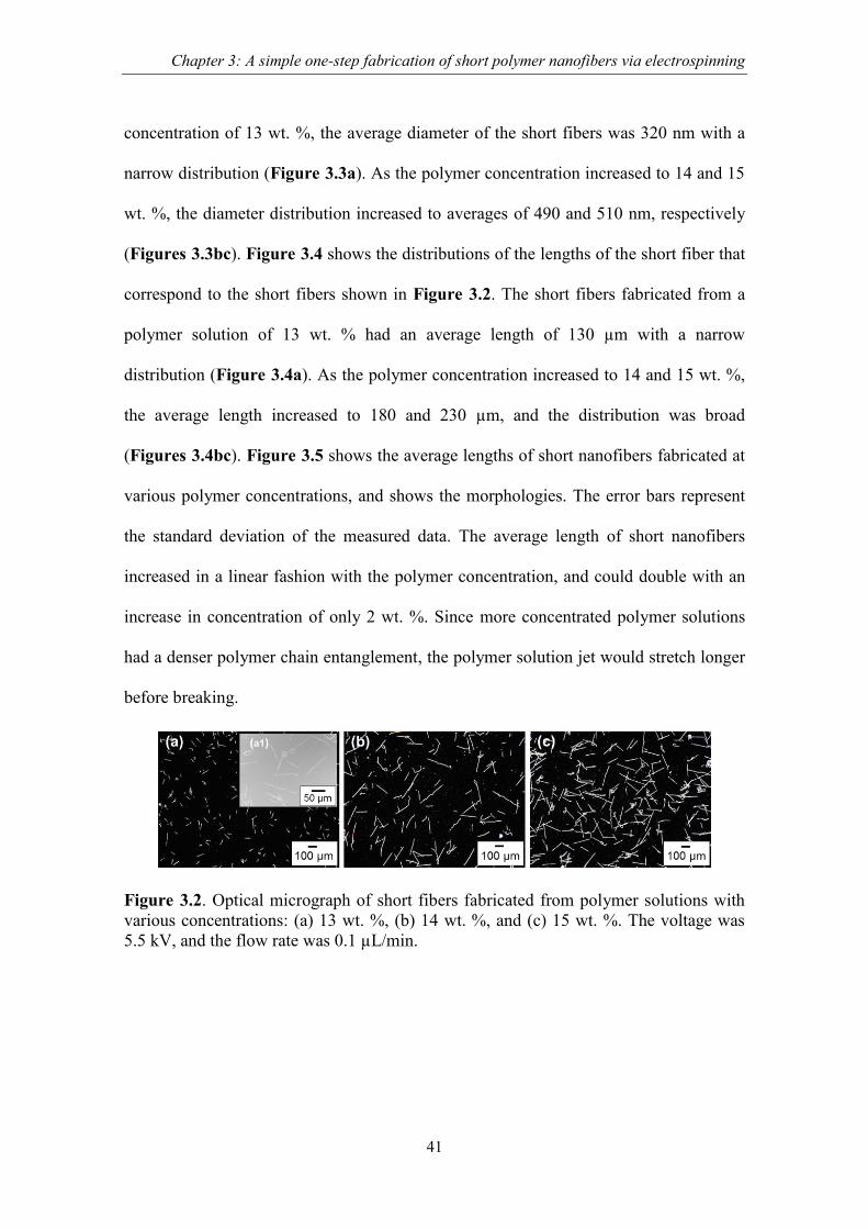
Chapter 3: A simple one-step fabrication of short polymer nanofibers via electrospinning
41
concentration of 13 wt. %, the average diameter of the short fibers was 320 nm with a
narrow distribution (Figure 3.3a). As the polymer concentration increased to 14 and 15
wt. %, the diameter distribution increased to averages of 490 and 510 nm, respectively
(Figures 3.3bc). Figure 3.4 shows the distributions of the lengths of the short fiber that
correspond to the short fibers shown in Figure 3.2. The short fibers fabricated from a
polymer solution of 13 wt. % had an average length of 130 µm with a narrow
distribution (Figure 3.4a). As the polymer concentration increased to 14 and 15 wt. %,
the average length increased to 180 and 230 µm, and the distribution was broad
(Figures 3.4bc). Figure 3.5 shows the average lengths of short nanofibers fabricated at
various polymer concentrations, and shows the morphologies. The error bars represent
the standard deviation of the measured data. The average length of short nanofibers
increased in a linear fashion with the polymer concentration, and could double with an
increase in concentration of only 2 wt. %. Since more concentrated polymer solutions
had a denser polymer chain entanglement, the polymer solution jet would stretch longer
before breaking.
Figure 3.2. Optical micrograph of short fibers fabricated from polymer solutions with
various concentrations: (a) 13 wt. %, (b) 14 wt. %, and (c) 15 wt. %. The voltage was
5.5 kV, and the flow rate was 0.1 µL/min.
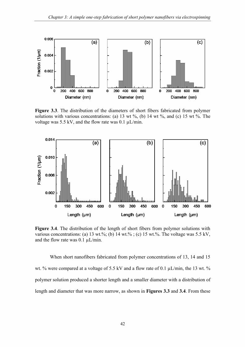
Chapter 3: A simple one-step fabrication of short polymer nanofibers via electrospinning
42
Figure 3.3. The distribution of the diameters of short fibers fabricated from polymer
solutions with various concentrations: (a) 13 wt %, (b) 14 wt %, and (c) 15 wt %. The
voltage was 5.5 kV, and the flow rate was 0.1 µL/min.
Figure 3.4. The distribution of the length of short fibers from polymer solutions with
various concentrations: (a) 13 wt.%; (b) 14 wt.% ; (c) 15 wt.%. The voltage was 5.5 kV,
and the flow rate was 0.1 µL/min.
When short nanofibers fabricated from polymer concentrations of 13, 14 and 15
wt. % were compared at a voltage of 5.5 kV and a flow rate of 0.1 µL/min, the 13 wt. %
polymer solution produced a shorter length and a smaller diameter with a distribution of
length and diameter that was more narrow, as shown in Figures 3.3 and 3.4. From these

Chapter 3: A simple one-step fabrication of short polymer nanofibers via electrospinning
43
results, the capability to control the length of short nanofibers was further investigated
using a 13 wt. % polymer solution.
Figure 3.5. The average length of short nanofibers fabricated from polymer solutions
with various concentrations. The voltage was 5.5 kV, and the flow rate was 0.1 µL/min.
The morphologies of the fabricated fibers are indicated in the Figure
3.3.2. The effect of flow rate and voltage on fiber length of short nanofibers
The effect of flow rate and voltage on the length of short nanofibers was
investigated using polymer solutions with concentrations of 13 wt. %.
The flow rate was varied from 0.01 to 0.7 µL/min, and the voltage was
maintained at 5.5 kV. Figure 3.6 shows the optical micrograph of short nanofibers
fabricated at flow rates of 0.02, 0.08 and 0.4 µL/min. A few short nanofibers were found
with a flow rate of 0.02 µL/min and an average length of short nanofibers of 65 µm
(Figure 3.6a). At a flow rate of 0.08 µL/min, the average length was 120 µm and the
production of short fibers was increased (Figure 3.6b). As the flow rate increased to 0.4
µL/min, the average length was 150 µm, and the production of short fibers was further
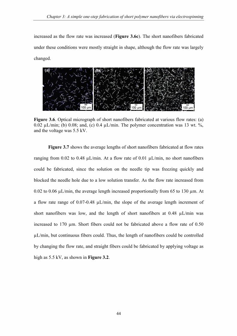
Chapter 3: A simple one-step fabrication of short polymer nanofibers via electrospinning
44
increased as the flow rate was increased (Figure 3.6c). The short nanofibers fabricated
under these conditions were mostly straight in shape, although the flow rate was largely
changed.
Figure 3.6. Optical micrograph of short nanofibers fabricated at various flow rates: (a)
0.02 µL/min; (b) 0.08; and, (c) 0.4 µL/min. The polymer concentration was 13 wt. %,
and the voltage was 5.5 kV.
Figure 3.7 shows the average lengths of short nanofibers fabricated at flow rates
ranging from 0.02 to 0.48 µL/min. At a flow rate of 0.01 µL/min, no short nanofibers
could be fabricated, since the solution on the needle tip was freezing quickly and
blocked the needle hole due to a low solution transfer. As the flow rate increased from
0.02 to 0.06 µL/min, the average length increased proportionally from 65 to 130 µm. At
a flow rate range of 0.07-0.48 µL/min, the slope of the average length increment of
short nanofibers was low, and the length of short nanofibers at 0.48 µL/min was
increased to 170 µm. Short fibers could not be fabricated above a flow rate of 0.50
µL/min, but continuous fibers could. Thus, the length of nanofibers could be controlled
by changing the flow rate, and straight fibers could be fabricated by applying voltage as
high as 5.5 kV, as shown in Figure 3.2.
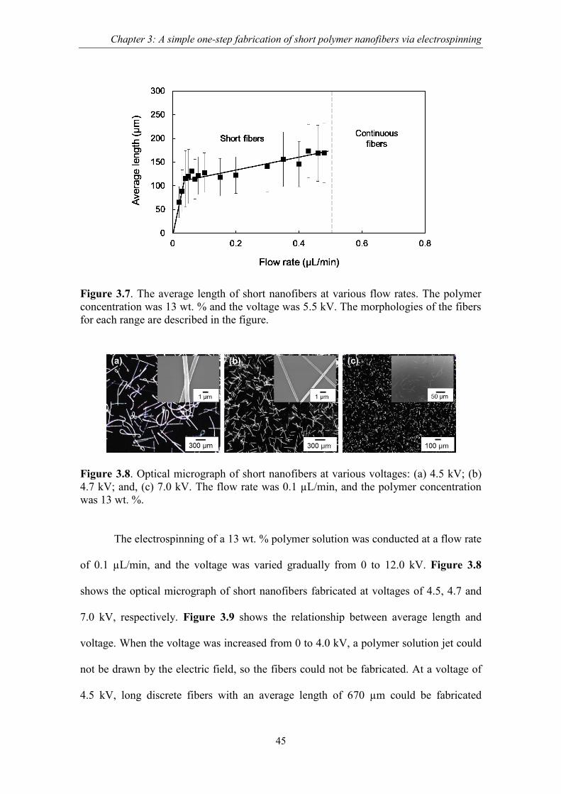
Chapter 3: A simple one-step fabrication of short polymer nanofibers via electrospinning
45
Figure 3.7. The average length of short nanofibers at various flow rates. The polymer
concentration was 13 wt. % and the voltage was 5.5 kV. The morphologies of the fibers
for each range are described in the figure.
Figure 3.8. Optical micrograph of short nanofibers at various voltages: (a) 4.5 kV; (b)
4.7 kV; and, (c) 7.0 kV. The flow rate was 0.1 µL/min, and the polymer concentration
was 13 wt. %.
The electrospinning of a 13 wt. % polymer solution was conducted at a flow rate
of 0.1 µL/min, and the voltage was varied gradually from 0 to 12.0 kV. Figure 3.8
shows the optical micrograph of short nanofibers fabricated at voltages of 4.5, 4.7 and
7.0 kV, respectively. Figure 3.9 shows the relationship between average length and
voltage. When the voltage was increased from 0 to 4.0 kV, a polymer solution jet could
not be drawn by the electric field, so the fibers could not be fabricated. At a voltage of
4.5 kV, long discrete fibers with an average length of 670 µm could be fabricated

Chapter 3: A simple one-step fabrication of short polymer nanofibers via electrospinning
46
(Figure 3.8a). The average diameter of a short nanofiber was 750 nm, and the fibers
had a curled shape that was caused by the weak stretching force from the applied
voltage. When the voltage was increased to 4.7 kV, short nanofibers 380 nm in diameter
could be fabricated, and the average length of the short nanofibers was decreased
rapidly to 250 µm (Figure 3.8b). As the voltage was varied from 4.9 to 5.5 kV, the
average length of short nanofibers ranged from 170 to 127 µm. The length of short
nanofiber was almost constant at a voltage of 6.0 to 8.5 kV. The average length of short
nanofibers fabricated at a voltage of 7 kV was 40 µm with a straight shape (Figure
3.8c). Above a voltage of 8.5 kV, the nanofibers could not be fabricated due to the
imbalance between fibers drawn by the strong electric field and a low flow rate.
Figure 3.9. The morphologies and average lengths of fibers at various voltages and a
flow rate of 0.1 µL/min for 13 wt. % polymer solutions.
Consequently, it was confirmed that the concentration of the polymer in the
solution was the most important factor in the fabrication of short nanofibers. Short
nanofibers could be fabricated using a 13 to 15 wt. % polymer solution. Using 13 wt. %
of polymer solution, the length of short nanofibers could be controlled in a range of

Chapter 3: A simple one-step fabrication of short polymer nanofibers via electrospinning
47
from 65 to 170 µm (Figures 3.6, 3.7) by altering the flow rate of the polymer solution,
whereas the length could be controlled in a range of from 37 to 670 µm by altering the
applied voltage (Figures 3.8, 3.9). However, the diameter of fibers fabricated by
applying low voltage was large and the shape was curled, although the short fibers were
longer in length. When the voltage was increased, a straight short nanofiber could be
fabricated.
3.3.3. Mechanism for the formation of short nanofiber
The fabrication mechanism for short nanofibers is discussed here based on the
observation of short nanofibers and on the conditions of electrospinning. Figure 3.10
shows the morphology of a typical short nanofiber fabricated at a flow rate 0.1 µL/min
with a voltage of 5.5 kV.
The Figure 3.10 compares the center (Figure 3.10b) with the edges (Figures 3.
10cd) of a short nanofiber. The diameter of the center portion ranged from 120 to 210
nm (Figure 3. 10b). The diameters of both edges of the short nanofiber were narrower
than the diameter of the center portion, and it was stretched to approximately 70 nm in
portions to within a range of 3 µm from the edge. This indicates that the fiber was
locally stretched, leading to a thinning of the diameter of the fiber and to a breakaway of
the fiber. This was due to the repulsive force of the surface charges and longitudinal
force by the external electric field [33].
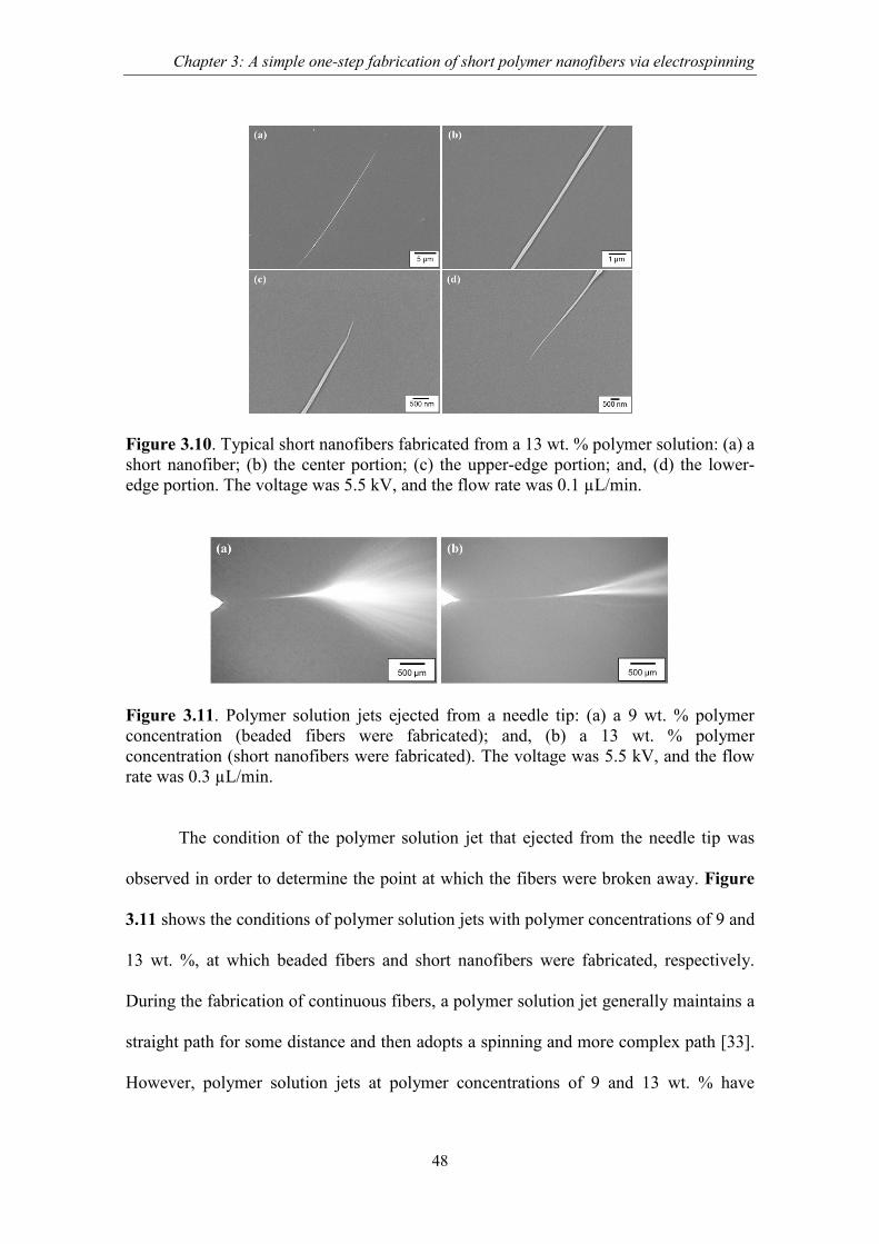
Chapter 3: A simple one-step fabrication of short polymer nanofibers via electrospinning
48
Figure 3.10. Typical short nanofibers fabricated from a 13 wt. % polymer solution: (a) a
short nanofiber; (b) the center portion; (c) the upper-edge portion; and, (d) the lower-
edge portion. The voltage was 5.5 kV, and the flow rate was 0.1 µL/min.
Figure 3.11. Polymer solution jets ejected from a needle tip: (a) a 9 wt. % polymer
concentration (beaded fibers were fabricated); and, (b) a 13 wt. % polymer
concentration (short nanofibers were fabricated). The voltage was 5.5 kV, and the flow
rate was 0.3 µL/min.
The condition of the polymer solution jet that ejected from the needle tip was
observed in order to determine the point at which the fibers were broken away. Figure
3.11 shows the conditions of polymer solution jets with polymer concentrations of 9 and
13 wt. %, at which beaded fibers and short nanofibers were fabricated, respectively.
During the fabrication of continuous fibers, a polymer solution jet generally maintains a
straight path for some distance and then adopts a spinning and more complex path [33].
However, polymer solution jets at polymer concentrations of 9 and 13 wt. % have
Chapter 3: A simple one-step fabrication of short polymer nanofibers via electrospinning
49
straight segments of approximately 2 mm in length, and are then spread to angles of 37o
and 15o, respectively. The spreading was due to a lateral perturbation caused by the
repulsive forces between surface charges of the electrified polymer solution jet [33].
This must be a feature of fabrication of short nanofibers that leads to the breakaway of
fibers. The difference in the spread angles for these two conditions was caused by the
viscosity of the polymer solution that in turn was caused by the differences in the
polymer concentration. When the polymer concentration was 9 wt. %, the spread angle
of the polymer solution jet was wide due to low viscosity, and beads formed on the
fibers due to a lack elasticity in the polymer solution jet [30]. When the polymer
concentration was 13 wt. %, the solution was also broken away by the longitudinal force
of an external electric field, although the spread angle of the polymer solution was
relatively narrow due to the higher viscosity. However, the polymer solution was
difficult to move in the solution jet, which resulted in short nanofibers with stretched
edges, as shown in Figure 3.10.
Based on observation of the short nanofibers (Figure 3.10), on the condition of
the polymer solution jets from the needle tip (Figure 3.11), and on the theoretical report
[32-34], the major factor that led to the fabrication of the short nanofibers was the
balance between the tensile strength of the polymer solution, the longitudinal force, and
the lateral perturbation of the surface charge on the polymer solution jet. Figure 3.12
shows the mechanism for short nanofiber fabrication and a diagram of the force in the
straight pass after ejection and at the point of breaking. Eq. 1 describes these factors
under equilibrium conditions on the cross-section area of the polymer solution jet,
Ft= ΔF cosθ + FL (1)

Chapter 3: A simple one-step fabrication of short polymer nanofibers via electrospinning
50
Figure 3.12. Diagram for the force of the polymer solution jet: (a) a straight pass after
ejection; and, (b) at the breaking point.
where the tensile strength, Ft, is the maximum force that a polymer solution jet can
withstand while being stretched before breaking. This force was affected by the mutual
attraction of the polymer molecules and the polymer-solvent interaction in the polymer
solution jet [20]. The high concentration of polymer could increase the mutual
interaction of polymer molecules, and, thus, the tensile strength increased, whereas the
selection of a solvent with a low surface tension could decrease the tensile strength. ΔF
is the force in the longitudinal direction due to the applied voltage. The FL is the force
due to the repulsive force, FR, between equal surface charges, which generates lateral
perturbation [33,34]. The angle θ is measured from the jet axis. The polymer solution jet
in the straight pass after ejection had a thick diameter with a straight shape and was
flowing in a single path. The ΔF of the applied voltage and the repulsive force FR of the
surface charge on the polymer solution jet stretched the polymer solution jet and moved
it forward (Figure 3.12a). In the straight path just before the jet was spread, the polymer
solution jet could not break away, because it had a thick diameter and the ΔF and
Chapter 3: A simple one-step fabrication of short polymer nanofibers via electrospinning
51
repulsive force FR of the surface charge were insufficient to break the polymer solution
jet (ΔF +FR < Ft). As the polymer solution jet moved farther away, its diameter thinned,
and the increase in the surface charge density resulted in an increase in the repulsive
force FR. The rapid increased in FR generated a lateral perturbation, FL, that made the
polymer solution jet spread. Thus, short nanofibers were fabricated by the breaking of
the fibers due to the resultant force of FL, and the ΔF cosθ surpassed the tensile strength
of the polymer solution jet (ΔF cosθ +FL > Ft) (Figure 3.12b).
3.5. Conclusions
The simple and one-step process fabrication of short polymer nanofibers has
been successfully developed based on electrospinning method. This proves that
electrospinning either can make short or continuous nanofiber. A polymer solution was
loaded into a syringe, and was then ejected by the application of high voltage. The effect
of the concentration of the polymer solution, the applied voltage, and the flow rate of
the polymer solution was investigated for its effect on the fabrication of short nanofibers,
and the following results were obtained. The concentration of the cellulose acetate
polymer in the solution was important factor which varied from 13 to 15 wt. %. The
length of fibers was increased by increasing the flow rate of the solution, and it was
decreased with an increase in applied voltage, resulting in controllable length of short
nanofibers at 37 to 670 µm. The edges of the short nanofibers were narrowed by
stretching. Observation of the polymer solution jet that was ejected from the needle tip
showed it passing straight, and then spreading due to lateral perturbations on its surface.
The breaking of the fibers into short nanofibers occurred because the repulsive force
Chapter 3: A simple one-step fabrication of short polymer nanofibers via electrospinning
52
from the surface charges and the longitudinal force from the applied voltage surpassed
the tensile strength of the polymer solution jet.
3.6. References
[1] J.N. Coleman, U. Khan, Y.K. Gun’ko, Mechanical reinforcement of polymers using
carbon nanotubes, Adv. Mater. 18 (2006) 689-706.
[2] L.N. Song, M. Xiao, X.H. Li, Y.Z. Meng, Short carbon fiber reinforced electrically
conductive aromatic polydisulfide/expanded graphite nanocomposites, Mater.
Chem. Phys. 93 (2005) 122-128.
[3] B. Yao, G. Wang, J. Ye, X. Li, Corrosion inhibition of carbon steel by polyaniline
nanofibers, Mater. Lett. 62 (2008) 1775-1778.
[4] S.A. Gordeyev, J.A. Ferreira, C.A. Bernardo, I.M. Ward, A promising conductive
material: highly oriented polypropylene filled with short vapor-grown carbon fibres,
Mater. Lett. 51 (2001) 32-36.
[5] E. Hablot, R. Matadi, S. Ahzi, L. Averous, Renewable biocomposites of dimmer
fatty acid-based polyamides with cellulose fibres: Thermal, physical, and
mechanical properties, Composites Sci. and Technol. 70 (2010) 504-509.
[6] S.Y. Fu, B. Lauke, E. Mader, C.Y. Yue, X. Hu, Tensile properties of short-glass-
fiber- and short-carbon-fiber-reinforced polypropylene composites, Compos.: Part A
Appl. Sci. Manuf. 31 (2000) 1117-1125.
[7] J. Huang, R.B. Kaner, A general chemical route to polyaniline nanofibers, J. Am.
Chem. Soc. 126 (2004) 851-855.
Chapter 3: A simple one-step fabrication of short polymer nanofibers via electrospinning
53
[8] A.E. Deniz, A. Celebiouglu, F. Kayaci, T. Uyar, Electrospun polymeric nanofibrous
composites containing TiO2 short nanofibers, Mater. Chem. Phys. 129 (2011) 701-
704.
[9] V.C. Li, K.H. Obla, Effect of fiber length variation on tensile properties of carbon-
fiber cement composites, Compos. Eng. 4 (1994) 947-964.
[10] J.L. Thomason, The Influence of fiber length and concentration on the properties of
glass fibre reinforced polypropylene: 5. Injection moulded long and short fibre PP,
Compos. Part A Appl. Sci. Manuf. 33 (2002) 1641-1652.
[11] H. Zhang, Z. Zhang, K. Friedrich, Effect of fiber length of wear resistance of short
carbon fiber reinforced epoxy composites, Compos. Sci. Technol. 67 (2007) 222-
230.
[12] F. Rezaei, R. Yunus, N.A. Ibrahim, Effect of fiber length on thermomechanical
properties of short carbon fiber reinforced polypropylene composites, Mater.
Design 30 (2009) 260-263.
[13] M.H. Al-Saleh, U. Sundararaj, Review of mechanical properties of carbon
nanofiber/polymer composites, Composites: Part A 42 (2011) 2126-2142.
[14] M. Endo, Y.A. Kim, T. Hayashi, K. Nishimura, T. Matusita, T. Mayashita, M.S.
Dresselhaus, Vapor-grown carbon fiber (VGCFs) basic properties and their battery
applications, Carbon 39 (2001) 1287-1297.
[15] G.G. Tibbetts, M.L. Lake, K.L. Strong, B.P. Rice, A review of vapor-grown carbon
nanofiber/polymer composites, Compos. Sci. Technol. 67 (2007) 1709-1718.
[16] A. Stoiljkovic, S. Agarwal, Short electrospun fibers by UV cutting method,
Macromol. Mater. Eng. 293 (2008) 895-899.

Chapter 3: A simple one-step fabrication of short polymer nanofibers via electrospinning
54
[17] C. Yoshikawa, K. Zhang, E. Zawadzak, H. Kobayashi, A novel shortened
electrospun nanofiber modified with a ‘concentrated’ polymer brush, Sci. Technol.
Adv. Mater. 12 (2011) 1-7.
[18] D. Li, Y. Xia, Electrospinning of nanofibers: Reinventing the wheel?, Adv. Mater.
16 (2004) 1151-1170.
[19] C.J. Luo, M. Nangrejo, M. Edirisinghe, A novel method of selecting solvents for
polymer electrospinning, Polymer 51 (2010) 1654-1662.
[20] C.J Luo, E. Stride, M. Edirisinghe, Mapping the influence of solubility and
dielectric constant on electrospinning polycaprolactone solutions, Macromolecules
45 (2012) 4669-4680.
[21] C.J. Luo, E. Stride, S. Stoyanov, E. Pelan, M. Edirisinghe Electrospinning short
polymer micro-fibres with average aspect ratios in the range of 10-200, J. Polym.
Res. 18 (2011) 2515-2522.
[22] I.W. Fathona, A. Yabuki, One-step fabrication of short electrospun fibers using an
electric spark, J. Mater. Proces. Technol. 213 (2013) 1894-1899.
[23] S. Mahalingam, M. Edirisinghe, Forming of polymer nanofibers by a pressurised
gyration process, Macromol. Rapid Commun. 34 (2013) 1134–1139.
[24] R. Konwarh, N. Karak M. Misra, Electrospun cellulose acetate nanofibers: The
present status and gamut of biotechnological applications, Biotechnol. Adv. 31
(2013) 421-437.
[25] S. Tungprapa, T. Puangparn, M. Weerasombut, I. Jangchud, P. Fakum, S.
Semongkhol, C. Meechaisue, P. Supaphol, Electrospun cellulose acetate fibers:
effect of solvent system on morphology and fiber diameter, Cellulose 14 (2007)
563-575.

Chapter 3: A simple one-step fabrication of short polymer nanofibers via electrospinning
55
[26] N. Bhardwaj, S.C. Kundu, Electrospinning: A fascinating fiber fabrication
technique, Biotechnol. Adv. 28 (2010) 325-347.
[27] Z.M. Huang, Y.Z. Zhang, M. Kotaki, S. Ramakrishna, A review on polymer
nanofibers by electrospinning and their applications in nanocomposites, Compos.
Sci. Technol. 63 (2003) 2223-2253.
[28] J.Y. Chen, H.C. Chen, J.N. Lin, C. Kuo, Effects of polymer media on electrospun
mesoporous titania nanofibers, Mater. Chem. Phys. 107 (2008) 480-487.
[29] K.H. Lee, H.Y. Kim, H.J. Bang, Y.H. Jung, S.G. Lee, The change of bead
morphology formed on electrospun polystyrene fibers, Polymer 44 (2003) 4029-
4034.
[30] J.H. Yu, S.V. Fridrikh, G.C. Rutledge, The role of elasticity in the formation of
electrospun fibers, Polymer 47 (2006) 4789-4797.
[31] S.L. Shenoy, W. Douglas, B.H.L. Frisch, G.E. Wnek, Role of chain entanglements
on fiber formation during electrospinning of polymer solutions: good solvent, non-
specific polymer–polymer interaction limit, Polymer 46 (2005) 3372-3384.
[32] D.H. Reneker, A.L. Yarin, H. Fong, S. Koombhongse, Bending instability of
electrically charged liquid jet of polymer solutions in electrospinning, J. Appl.
Phys. 87 (2000) 4531-4547.
[33] M.M. Hohman, M. Shin , G. Rutledge, M.P. Brenner, Electrospinning and
electrically forced jets. I. Stability theory, Phys. Fluids 13 (2001) 2201-2220.
[34] M.M. Hohman , M. Shin , G. Rutledge, M.P. Brenner, Electrospinning and
electrically forced jets. II. Applications, Phys. Fluids 13 (2001) 2221-2236.

56
Chapter 4
One-step fabrication of short nanofibers by electrospinning: Effect of
needle size on nanofiber length.
4.1. Introduction
Recently, researches on short fibers have been performed intensively due to its
ability to enhance the tensile strength, conductivity, corrosion resistance, and thermal
stability of the polymer composite for many applications, for example, aerospace,
automotive industries, corrosion protection, flexible display, or electrode, etc. [1-4].
Electrospinning has been employed by several researchers to produce fibers due to its
simple process. However, the post processing are always needed to produce the short
fibers from the as spun continuous fibers. Stoiljkovic et al. have used the concept of a
photocross-linking reaction upon UV radiation as a secondary process [5], whereas
Yoshikawa et al. have employed the mechanical cutting of electrospun fibers dispersed
in the water using homogenizer as secondary process [6]. The direct fabrication of short
fibers using electrospinning method has been reported and performed [7,8]. Luo et al.
have reported the direct fabrication of short micro-fibers with aspect ratio of 10-200 by
altering the molecular weight of polymethylsisesquioxane (PMSQ) and using the
volatile solvent [7]. In the chapter 2, the electric spark was utilized to cut the fibers
during electrospinning [8].
In this chapter, a one-step process for the production of short polymer nanofibers
using an electrospinning technique is proposed. Differing from our previous work which
describe in chapter 2 [8], the electric spark generator was uninstalled from the
electrospinning setup. The polymer solution was loaded into a syringe with a needle,
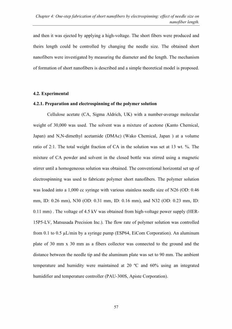
Chapter 4: One-step fabrication of short nanofibers by electrospinning: effect of needle size on
nanofiber length.
57
and then it was ejected by applying a high-voltage. The short fibers were produced and
theirs length could be controlled by changing the needle size. The obtained short
nanofibers were investigated by measuring the diameter and the length. The mechanism
of formation of short nanofibers is described and a simple theoretical model is proposed.
4.2. Experimental
4.2.1. Preparation and electrospinning of the polymer solution
Cellulose acetate (CA, Sigma Aldrich, UK) with a number-average molecular
weight of 30,000 was used. The solvent was a mixture of acetone (Kanto Chemical,
Japan) and N,N-dimethyl acetamide (DMAc) (Wako Chemical, Japan ) at a volume
ratio of 2:1. The total weight fraction of CA in the solution was set at 13 wt. %. The
mixture of CA powder and solvent in the closed bottle was stirred using a magnetic
stirrer until a homogeneous solution was obtained. The conventional horizontal set up of
electrospinning was used to fabricate polymer short nanofibers. The polymer solution
was loaded into a 1,000 cc syringe with various stainless needle size of N26 (OD: 0.46
mm, ID: 0.26 mm), N30 (OD: 0.31 mm, ID: 0.16 mm), and N32 (OD: 0.23 mm, ID:
0.11 mm) . The voltage of 4.5 kV was obtained from high-voltage power supply (HER-
15P5-LV, Matsusada Precision Inc.). The flow rate of polymer solution was controlled
from 0.1 to 0.5 µL/min by a syringe pump (ESP64, EiCom Corporation). An aluminum
plate of 30 mm x 30 mm as a fibers collector was connected to the ground and the
distance between the needle tip and the aluminum plate was set to 90 mm. The ambient
temperature and humidity were maintained at 20 ºC and 60% using an integrated
humidifier and temperature controller (PAU-300S, Apiste Corporation).

Chapter 4: One-step fabrication of short nanofibers by electrospinning: effect of needle size on
nanofiber length.
58
4.2.2. Observation of short nanofibers
The prepared short nanofibers were observed by SEM (JSM-6340F, JEOL Ltd.)
with an acceleration voltage of 20 kV. The shape of the short fibers was evaluated by
measuring the diameter at the centers and the edges of the fibers. The lengths and
diameters of the short nanofibers were measured using the ruler function of image
processing software during observation using a digital microscope with a resolution of
2.11 MP (VH-8000, Keyence Corporation) and a high-range zoom lens with a
magnification ranging from 450 - 3,000x (VH-Z450, Keyence Corporation).
4.3. Results and discussion
4.3.1. Effect of needle size on the fiber diameter and length
The electrospun fibers were fabricated from a polymer solution of 13 wt. %
concentration, and the morphology of the fibers was observed. Three needles with
different inner diameter of N26, N30, and N32 were used. The fiber jet could be drawn
at voltage of 4.5 kV, and the flow rate of the polymer solution was varied gradually
from 0.1 to 0.5 µL/min. As results, two types of morphologies of fibers were
recognized: the short nanofibers were fabricated at flow rate ranging from 0.1 to 0.48
µL/min and continuous fibers were fabricated at flow rate 0.5 µL/min. For further
investigation, a voltage of 4.5 kV and flow rate of 0.1 µL/min were employed.
Figures 4.1a, 4.1b, and 4.1c show the optical micrographs and SEM images of
the short nanofibers fabricated from different needles of N26, N30, and N32,
respectively. As the needle inner diameter was increased from 0.16 to 0.26 mm, which
is N30 and N26, the averages diameter of short fibers were increased approximately
twice, that is from 170 to 370 nm. At the N32 the average short fiber diameter was 168
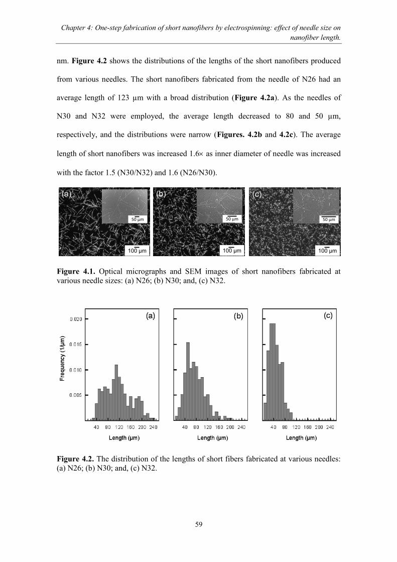
Chapter 4: One-step fabrication of short nanofibers by electrospinning: effect of needle size on
nanofiber length.
59
nm. Figure 4.2 shows the distributions of the lengths of the short nanofibers produced
from various needles. The short nanofibers fabricated from the needle of N26 had an
average length of 123 µm with a broad distribution (Figure 4.2a). As the needles of
N30 and N32 were employed, the average length decreased to 80 and 50 µm,
respectively, and the distributions were narrow (Figures. 4.2b and 4.2c). The average
length of short nanofibers was increased 1.6 as inner diameter of needle was increased
with the factor 1.5 (N30/N32) and 1.6 (N26/N30).
Figure 4.1. Optical micrographs and SEM images of short nanofibers fabricated at
various needle sizes: (a) N26; (b) N30; and, (c) N32.
Figure 4.2. The distribution of the lengths of short fibers fabricated at various needles:
(a) N26; (b) N30; and, (c) N32.
100 µm 100 µm 100 µm
50 µm 50 µm 50 µm
(a) (b) (c)
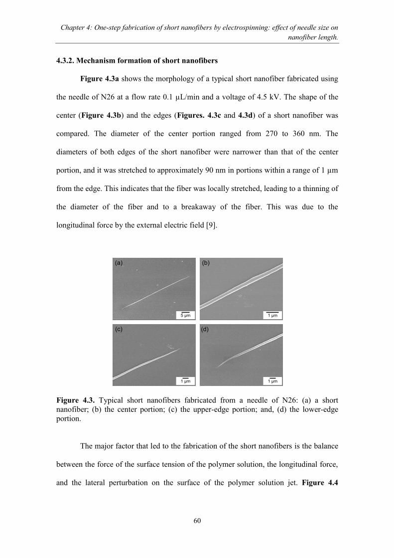
Chapter 4: One-step fabrication of short nanofibers by electrospinning: effect of needle size on
nanofiber length.
60
4.3.2. Mechanism formation of short nanofibers
Figure 4.3a shows the morphology of a typical short nanofiber fabricated using
the needle of N26 at a flow rate 0.1 µL/min and a voltage of 4.5 kV. The shape of the
center (Figure 4.3b) and the edges (Figures. 4.3c and 4.3d) of a short nanofiber was
compared. The diameter of the center portion ranged from 270 to 360 nm. The
diameters of both edges of the short nanofiber were narrower than that of the center
portion, and it was stretched to approximately 90 nm in portions within a range of 1 µm
from the edge. This indicates that the fiber was locally stretched, leading to a thinning of
the diameter of the fiber and to a breakaway of the fiber. This was due to the
longitudinal force by the external electric field [9].
Figure 4.3. Typical short nanofibers fabricated from a needle of N26: (a) a short
nanofiber; (b) the center portion; (c) the upper-edge portion; and, (d) the lower-edge
portion.
The major factor that led to the fabrication of the short nanofibers is the balance
between the force of the surface tension of the polymer solution, the longitudinal force,
and the lateral perturbation on the surface of the polymer solution jet. Figure 4.4
5 µm
1 µm
1 µm
1 µm
(a) (b)
(c) (d)

Chapter 4: One-step fabrication of short nanofibers by electrospinning: effect of needle size on
nanofiber length.
61
represents the mechanism for short nanofiber fabrication. Eq. 1 describes these factors
under equilibrium conditions,
πRσ=ΔF (1)
where the surface tension σ is the cohesive force of the polymer molecules on the
surface with radius R. The term ΔF is the resultant force in the longitudinal direction
that is the ratio between the Coulomb force, Fq, and the net cohesive force, Fc, in the
polymer solution jet (ΔF= Fq – Fc). The polymer solution jet in the straight pass after
ejection had a straight shape and was flowing in a single path. On the cross-section of
this polymer solution jet, the ΔF slightly dominated the surface tension, so the polymer
solution jet was stretched and moved forward (Figure 4.4a). In this straight path, the
polymer solution jet could not break away, because it had a thick diameter of R which
has almost same in size with inner diameter of needle. As the polymer solution jet
moved further away, its diameter thinned with a large ratio becomes r and then the
longitudinal force of the external electric field easily broke it. Thus, short nanofibers
were fabricated by the breaking of fibers due to the significant imbalance of force
between the surface tension of the polymer solution and the resultant influence of
Coulomb force, Fq from the applied voltage, and the net cohesive force, Fc, of polymer
molecule confined on the polymer solution jet (Figure 4.4b). From this mechanism, the
broken fiber has correlation with the inner-diameter of needle, and the shorter fibers
were fabricated from the smaller inner diameter of needle.
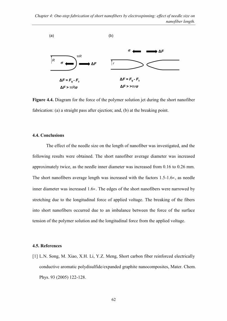
Chapter 4: One-step fabrication of short nanofibers by electrospinning: effect of needle size on
nanofiber length.
62
Figure 4.4. Diagram for the force of the polymer solution jet during the short nanofiber
fabrication: (a) a straight pass after ejection; and, (b) at the breaking point.
4.4. Conclusions
The effect of the needle size on the length of nanofiber was investigated, and the
following results were obtained. The short nanofiber average diameter was increased
approximately twice, as the needle inner diameter was increased from 0.16 to 0.26 mm.
The short nanofibers average length was increased with the factors 1.5-1.6, as needle
inner diameter was increased 1.6. The edges of the short nanofibers were narrowed by
stretching due to the longitudinal force of applied voltage. The breaking of the fibers
into short nanofibers occurred due to an imbalance between the force of the surface
tension of the polymer solution and the longitudinal force from the applied voltage.
4.5. References
[1] L.N. Song, M. Xiao, X.H. Li, Y.Z. Meng, Short carbon fiber reinforced electrically
conductive aromatic polydisulfide/expanded graphite nanocomposites, Mater. Chem.
Phys. 93 (2005) 122-128.
σ ΔF
ΔF = Fq - Fc
ΔF > πRσ
R
πR
σ ΔF
ΔF = Fq - Fc
ΔF > >πrσ
r
(a) (b)
Chapter 4: One-step fabrication of short nanofibers by electrospinning: effect of needle size on
nanofiber length.
63
[2] B. Yao, G. Wang, J. Ye, X. Li, Corrosion inhibition of carbon steel by polyaniline
nanofibers, Mater. Lett. 62 (2008) 1775-1778.
[3] S.A. Gordeyev, J.A. Ferreira, C.A. Bernardo, I.M. Ward, A promising conductive
material: highly oriented polypropylene filled with short vapour-grown carbon
fibres, Mater. Lett. 51 (2001) 32-36.
[4] E. Hablot, R. Matadi, S. Ahzi, L. Averous, Renewable biocomposites of dimmer
fatty acid-based polyamides with cellulose fibres: Thermal, physical and mechanical
properties, Compos. Sci. Technol. 70 (2010) 504-509.
[5] A. Stoiljkovic, S. Agarwal, Short electrospun fibers by UV cutting method,
Macromol. Mater. Eng. 293 (2008) 895-899.
[6] C. Yoshikawa, K. Zhang, E. Zawadzak, H. Kobayashi, A novel shortened
electrospun nanofiber modified with a ‘concentrated’ polymer brush, Sci. Technol.
Adv. Mater. 12 (2011) 1-7.
[7] C.J. Luo, E. Stride, S. Stoyanov, E. Pelan, M. Edirisinghe, Electrospinning short
polymer micro-fibres with average aspect ratios in the range of 10-200, J. Polym.
Res. 18 (2011) 2515-2522.
[8] I.W. Fathona, A. Yabuki, One-step fabrication of short electrospun fibers using an
electric spark, J. Mater. Proces. Technol. 213 (2013) 1894-1899.
[9] D.H. Reneker, A.L. Yarin, H. Fong, S. Koombhongse, Bending instability of
electrically charged liquid jet of polymer solutions in electrospinning, J. Appl. Phys.
87 (2000) 4531-4547.

64
Chapter 5
Short electrospun composite nanofibers: Effects of nanoparticle
concentration and surface charge on fiber length
5.1. Introduction
Research into composite fibers has recently intensified in various industrial
fields. The presence of nanoparticles has resulted in an enhancement of the mechanical,
photocatalytic, electrical, thermal, and optical properties of the fibers [1-16]. Nano-sized
composite fibers can utilize the characteristic features of nanoparticles such as tunable
electronic band gaps and a high surface area. Yu et al. have reported that the
photoluminescent property of cadmium sulfate quantum-dots with a particle-size-
dependent electronic band gap could be enhanced by embedding the cadmium quantum-
dots into polyethylene oxide fiber [8]. This kind of material is expected to be applicable
to the preparation of electroluminescent devices and nano-optoelectronic devices [8].
The photocatalytic efficiency of TiO 2 in the nanofiber morphology is highly superior to
that of the TiO2 film or nanoparticles [17,18]. The enhancement of photocatalytic
efficiency is due to the high surface areas and high porosity of the TiO2 nanofibers. The
short fibers have several advantages compared to continuous fiber [19-21]. Anil et al.
have reported using the short nanofibers as a drug carrier with a diameter and length of
4 nm and 50-400 nm, respectively, that could deliver the drugs to a tumor site within a
much shorter period of time compared with that of a spherical nanoparticle [19]. Fu et al.
report that the special regular short nanofiber microstructure has had a great impact on
photocatalytic performance and removal efficiency, and that it greatly increases the

Chapter 5: Short electrospun composite nanofibers: Effects of nanoparticle concentration and
surface charge on fiber length
65
permeability of visible light, expands the reaction zone, and promotes photocatalytic
efficiency [20]. Jiang et al. report that the short electrospun polyimide fiber dispersed in
a polymer matrix enhances the mechanical properties of a polymer matrix with the
addition of only 2 wt. % of short fiber, whereas the amount of continuously long
polyimide fiber required to even approximate the mechanical strength was much higher
as 38 wt. % [21]. Therefore, the studies of both effects of nanoparticles and processing
parameters on the fabrication of short composite fibers are relevant in order to find the
optimum performance of short composite fibers that could contribute to further research
such as drug carriers, material templates for hollow or porous structures of metal oxide,
membranes, and high tensile and modulus materials.
The method that is commonly used to fabricate short fibers is called the vapor-
grown technique. With this technique, a controllable length of short fibers can be
achieved by altering the catalyst size, temperature processing, and catalyst activity
[22,23]. This technique is feasible for industrial applications; however, several
drawbacks persist, such as an extended chemical route and post-processing, which are
necessary in order to enhance the physical properties of the carbon fibers. A novel
method to fabricate short fibers is called the pressurized gyration process, which
combines centrifugal spinning and solution blowing [24]. With this process, the
diameter and length of obtained fibers are 60-1000 nm and 200-800 mm, respectively.
This method offers mass production capabilities, but the length of the nanofibers is too
long for use as filler. These problems have motivated many researchers to find effective
methods for the fabrication of short fibers or short composite fibers.
Electrospinning is a simple and reliable method for the fabrication of fibers with
diameters in the nano to micro scale. A polymer solution is electrified by high voltage to

Chapter 5: Short electrospun composite nanofibers: Effects of nanoparticle concentration and
surface charge on fiber length
66
form a cone jet, which stretches to fabricate the nanofibers. Composite nanofiber can be
produced with this technique by utilizing a suspension of polymer/nanoparticles as a
precursor [25-27]. The nanofibers prepared via the electrospinning method are generally
continuous, and secondary processes must be applied in order to fabricate short
nanofibers. Ali et al. used mechanical crushing as a secondary process in order to
fabricate TiO2 short nanofibers from the continuous electrospun fibers of
polyvinylpirrolidone/TiO2 [28]. In the chapter 2 and 3, short electrospun polymer
nanofibers could be fabricated in a one-step process. In these methods, the short
nanofibers could be fabricated by cutting the continuous fibers using an electric spark
[29], and by regulating the concentration of the polymer, the flow rate, and the working
voltage [30]. One-step process methods of electrospinning can be applied to the
fabrication of short composite nanofibers by replacing the polymer solution with a
polymer/nanoparticle solution.
In this chapter, the polymer/nanoparticle solutions consisted of cellulose acetate,
TiO2 nanoparticles, and organic solvents that were electrospun to fabricate short
composite nanofibers. The goal of this study was to investigate the effect of the
concentrations and the surface charges of the nanoparticles on the length of fabricated
short composite nanofibers that could contribute to the development of drug delivery
systems, material template fabrication, and fibril filler for composite materials. The
morphologies of the fabricated short composite nanofibers and the conditions of the
electrospun jets of the polymer/nanoparticle solutions were observed to elucidate the
mechanism of fabrication for short composite nanofibers.
Chapter 5: Short electrospun composite nanofibers: Effects of nanoparticle concentration and
surface charge on fiber length
67
5.2. Experimental methods
5.2.1. Preparation of the polymer/nanoparticle solutions
The polymer/nanoparticle solutions consisted of cellulose acetate polymer
powder with a molecular weight of 30,000 (Sigma Aldrich, UK), TiO2 nanoparticles
with a diameter of 10-30 nm (TTO-51C (rutile type), Ishihara Sangyo Kaisha, Ltd.,
Japan), and organic solvents that consisted of acetone (>99.5%, Kanto Chemical, Japan)
and N,N-dimethyl acetamide (DMAc) (>99.5%, Sigma Aldrich, UK) with a volume
ratio of 2:1. The concentration of the polymer was set at 13 wt. % and the
concentrations of TiO2 nanoparticles in the polymer/nanoparticle solutions were varied
from 0.5 to 17 wt. % for the fabrication of short composite nanofibers. The prepared
polymer/nanoparticle solutions turned to short composite nanofibers with 4 to 56 wt. %
nanoparticles after evaporation of the organic solvent. The suspension was prepared by
pouring the TiO2 nanoparticles into 15 mL of organic solvent, which was then subjected
to an ultrasonic homogenizer in a closed bottle for 30 min. The polymer powder was
added into the suspension of TiO2 nanoparticles and organic solvent and then stirred and
homogenized for 3 h. During the ultrasound-homogenization process, the weight of the
suspension decreased as a portion of the organic solvent was evaporated. After
dispersion, organic solvent was added to compensate for the weight loss of the
suspension and to return the weight ratio of each component to the original amount.
Polymer/nanoparticle solutions of various pHs were prepared using either aqueous
sodium hydroxide or hydrochloric acid. The pH of the solution was measured using a
digital pH meter (Cyberscan pH 110, EUTECH INSTRUSMENTS) with a glass
electrode (EC620131, EUTECH INSTRUSMENTS). The viscosity of each solution was
measured using a viscometer (TVE-22H cone plate type, Toki Sangyo Co., Ltd, Japan).
Chapter 5: Short electrospun composite nanofibers: Effects of nanoparticle concentration and
surface charge on fiber length
68
5.2.2. Electrospinning of the polymer/nanoparticle solutions
A conventional electrospinning setup was used to fabricate short composite
nanofibers. The polymer/nanoparticle solutions were loaded into a 1,000 cc syringe
(TTL 2-432, Hamilton Company) with a stainless needle (OD: 0.46 mm, ID: 0.26 mm).
A high-voltage power supply (HER-15P5-LV, Matsusada Precision Inc.) was connected
to the stainless needle to electrify the polymer/nanoparticle solutions. The voltage was
increased gradually to find the appropriate voltage for conducting electrospinning. The
flow rates of polymer/nanoparticle solutions were controlled via a micro syringe pump
(ESP64, EiCom Corporation). The voltage and the flow rates were set at 5.5 kV and 0.1
µL/min, respectively [30]. A 30 mm x 30 mm aluminum plate that was used to collect
the electrospun nanofibers was connected to the ground, and a 3 mm x 3 mm silicon
wafer was attached to observe the nanofibers. The distance between the needle tip and
the aluminum plate was set at 90 mm. The ambient temperature and humidity were
maintained at 20 ºC and 60% using a temperature controller and an integrated
humidifier (PAU-300S, Apiste Corporation), respectively.
5.2.3. Measurement of the zeta potential of TiO2 nanoparticles
The zeta potential of the nanoparticles was measured at pH values ranging from
2 to 11 via a Nanozeta apparatus (Malvern Zetasizer, Nano ZS, UK). The TiO2
nanoparticles were dispersed into 100 mL of deionized water with a concentration 0.05
wt. %. Then, 1 M of either aqueous sodium hydroxide or hydrochloride acid was
dropped gradually into the solution to control the pH.
Chapter 5: Short electrospun composite nanofibers: Effects of nanoparticle concentration and
surface charge on fiber length
69
5.2.4. Observation of short composite nanofibers
The diameters and the lengths of fabricated short composite nanofibers were
measured using the ruler function of image processing software during observation with
a digital microscope at a resolution of 2.11 megapixels (VH-8000, Keyence
Corporation). Two types of lenses, a low-range lens and a high-range zoom lens with a
magnification ranging from 25-3,000x (VH-Z450, Keyence Corporation), were used for
the observation. The distribution and the average lengths of the short composite fibers
were determined for more than 200 fibers. The morphologies of the short composite
nanofibers were observed using a scanning electron microscope (SEM) (JSM-6340F,
JEOL Ltd.) with a maximum magnification factor of 650,000x and a resolution of 1.2
nm at an acceleration voltage of 20 kV.
The conditions of the electrospinning jets of various polymer/nanoparticle
solutions were observed using a CCD camera with a resolution of 0.4 megapixels,
twice-digital zoom, and 0.8 lux of minimum illumination (MTV-73x11HN, Mintron
Enterprise Co., Ltd). A monocular optical lens with a diameter of 50 mm and a
magnification factor of 8 (M0850, Specwell) was attached to the CCD camera. The
images were taken at a speed of 30 fps and were recorded on a personal computer.
5.3. Results and discussion
5.3.1. The effect of nanoparticle concentration on the length of short composite
nanofibers
We previously reported that short nanofibers could be fabricated using a 13
wt. % cellulose acetate polymer solution [29,30]. Therefore, 13 wt. % concentrations of
polymer were chosen. Figure 5.1 shows the short composite nanofibers with various

Chapter 5: Short electrospun composite nanofibers: Effects of nanoparticle concentration and
surface charge on fiber length
70
concentrations of nanoparticles fabricated by the electrospinning of a 13 wt. % polymer
solution at a voltage of 5.5 kV and a flow rate of 0.1 L/min. The short plain polymer
nanofibers without nanoparticles were almost straight, although some curling was
observed toward the ends of the short nanofibers (Figure 5.1a). The diameters of the
short plain nanofibers ranged from 110 to 150 nm. The short composite nanofibers
produced using a 4 wt. % concentration of nanoparticles were also straight and had a
smooth surface—a few nanoparticles were observed on the surface of the fibers (Figure
5.1b). The diameters of the short composite nanofibers were larger, and ranged from
250 to 270 nm. The short composite nanofibers with a 5 to 7 wt. % concentration of
nanoparticles showed morphologies that were similar to those produced using a 4 wt. %
concentration of nanoparticles. The morphology of short composite nanofibers with a 38
wt. % concentration of nanoparticles was also straight and a bead was recognized on
each of the short composite nanofibers (Figure 5.1c). Some nanoparticles were
observed on the surface of the nanofibers. The diameters of short composite nanofibers
with a 38 wt. % concentration of nanoparticles were larger, and ranged from 310 to 370
nm. The short composite nanofibers with a 40 to 50 wt. % concentration of
nanoparticles had a similar morphology to the nanofibers with a 38 wt. % concentration
of nanoparticles.
Figure 5.2 shows the distribution of the lengths of the short plain and composite
nanofibers from Figure 5.1. The short plain polymer nanofibers and the short composite
nanofibers with a 4 wt. % concentration of nanoparticles had an average length of 120
and 112 µm, respectively, with a broad distribution (Figures 5.2ab). As the
concentration of nanoparticles was increased to 38 wt. %, the average length of the short
composite nanofibers decreased to 47 µm, and the distribution narrowed (Figure 5. 2c).
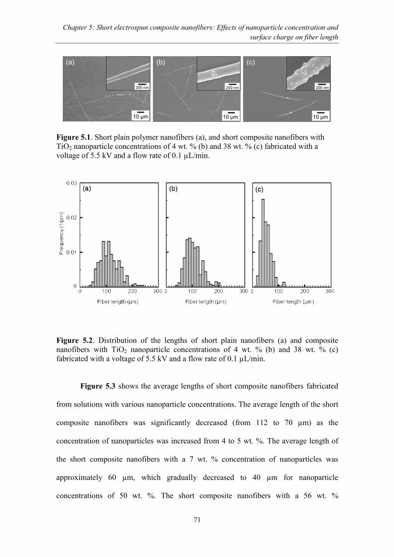
Chapter 5: Short electrospun composite nanofibers: Effects of nanoparticle concentration and
surface charge on fiber length
71
Figure 5.1. Short plain polymer nanofibers (a), and short composite nanofibers with
TiO2 nanoparticle concentrations of 4 wt. % (b) and 38 wt. % (c) fabricated with a
voltage of 5.5 kV and a flow rate of 0.1 µL/min.
Figure 5.2. Distribution of the lengths of short plain nanofibers (a) and composite
nanofibers with TiO2 nanoparticle concentrations of 4 wt. % (b) and 38 wt. % (c)
fabricated with a voltage of 5.5 kV and a flow rate of 0.1 µL/min.
Figure 5.3 shows the average lengths of short composite nanofibers fabricated
from solutions with various nanoparticle concentrations. The average length of the short
composite nanofibers was significantly decreased (from 112 to 70 µm) as the
concentration of nanoparticles was increased from 4 to 5 wt. %. The average length of
the short composite nanofibers with a 7 wt. % concentration of nanoparticles was
approximately 60 µm, which gradually decreased to 40 µm for nanoparticle
concentrations of 50 wt. %. The short composite nanofibers with a 56 wt. %
(b)10 µm
(a) (b) (c)
200 nm
10 µm 10 µm
200 nm 200 nm

Chapter 5: Short electrospun composite nanofibers: Effects of nanoparticle concentration and
surface charge on fiber length
72
concentration of nanoparticles could no longer be electrospun. This was caused by the
high viscosity of the solution. During the fabrication of short composite nanofibers, the
threshold concentration for added nanoparticles that resulted in significant changes in
fiber length was found to be 5 wt. %.
Figure 5.3. Average lengths of short composite nanofibers containing various
nanoparticle concentrations.
The viscosities of the polymer/nanoparticle solutions with various nanoparticle
concentrations are shown in Figure 5.4. The concentration of a polymer/nanoparticle
solution, which is the x-axis in the Figure, corresponds to the x-axis of Figure 5.3; for
instance, a concentration of 0.5 wt. % of polymer/nanoparticle solution corresponded to
a concentration of 4 wt. % of nanoparticles for short composite nanofibers. The
viscosity of the polymer/nanoparticle solutions gradually increased as the nanoparticle
concentration was increased. However, the added-nanoparticle-concentration threshold
(5 wt. %) that amounted to a significant change in fiber length, as shown in Figure 5.3,
was not related to the viscosity of the polymer/nanoparticle solution. These results
0
20
40
60
80
100
120
140
0 10 20 30 40 50 60
Ave
rag
e f
ibe
r le
ng
th (
µm
)
Nanoparticle concentration in fibers (wt. %)
56
No e
lectr
ospin
nin
g

Chapter 5: Short electrospun composite nanofibers: Effects of nanoparticle concentration and
surface charge on fiber length
73
showed that the viscosity of the polymer/nanoparticle solutions did not determine the
length of the short composite nanofibers.
Figure 5.4. Viscosity of the polymer/nanoparticle solutions of various TiO2
concentrations. The polymer concentration in the solutions was 13 wt. %.
5.3.2. The effect of the zeta potential of nanoparticles on composite nanofiber
length
The dispersion conditions of the nanoparticles in the polymer nanofibers were an
important parameter, and the length of the short composite nanofibers might have been
related to the dispersion conditions. Veronovsky et al. have reported that the dispersion
condition of TiO2 was affected by its zeta potential [31]. Therefore, in order to confirm
the effect of the dispersion of TiO2 on the length of short composite nanofibers, the zeta
potential of TiO2 nanoparticles in the solution was controlled by changing the pH of the
solution. Figure 5.5 shows the zeta potentials of TiO2 nanoparticles dispersed in the
deionized water at various pHs. The zeta potentials of the nanoparticles were gradually
decreased from 25 to -34 mV with an increase in the pH of the solution. The pH of the
0
200
400
600
800
1000
1200
0 5 10 15
Vis
co
sity (
mP.s
)
Nanoparticle concentration in solution (wt. %)
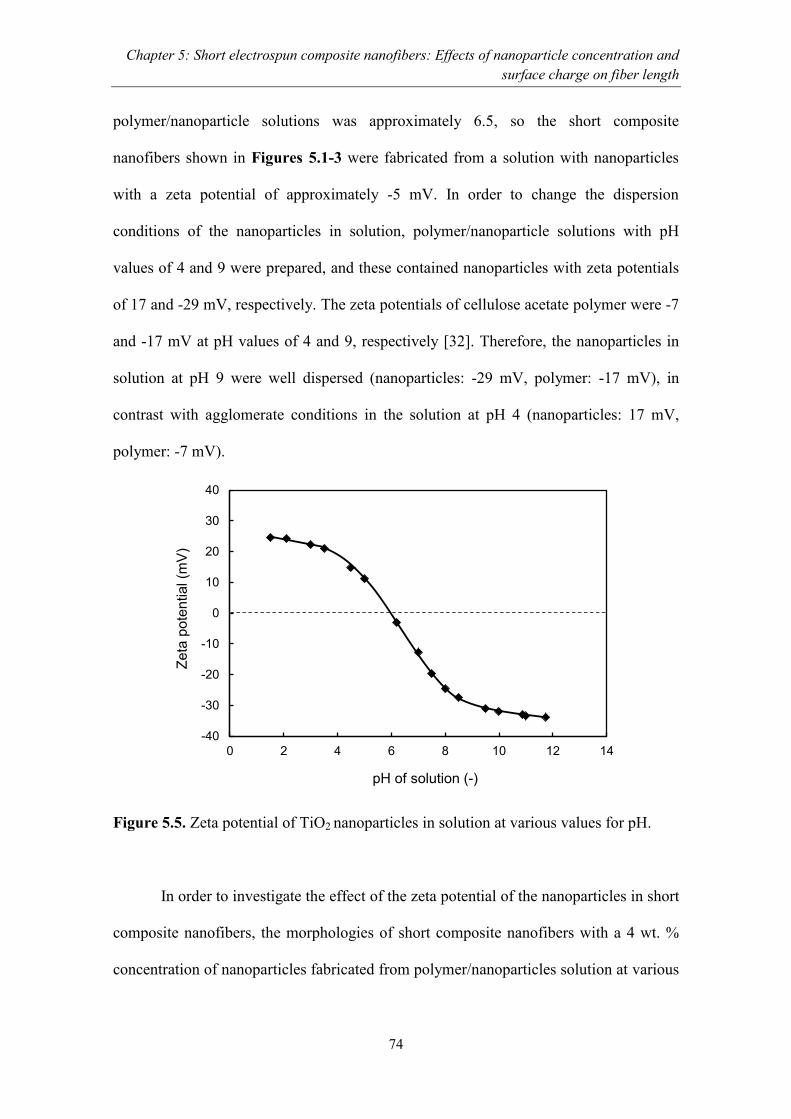
Chapter 5: Short electrospun composite nanofibers: Effects of nanoparticle concentration and
surface charge on fiber length
74
polymer/nanoparticle solutions was approximately 6.5, so the short composite
nanofibers shown in Figures 5.1-3 were fabricated from a solution with nanoparticles
with a zeta potential of approximately -5 mV. In order to change the dispersion
conditions of the nanoparticles in solution, polymer/nanoparticle solutions with pH
values of 4 and 9 were prepared, and these contained nanoparticles with zeta potentials
of 17 and -29 mV, respectively. The zeta potentials of cellulose acetate polymer were -7
and -17 mV at pH values of 4 and 9, respectively [32]. Therefore, the nanoparticles in
solution at pH 9 were well dispersed (nanoparticles: -29 mV, polymer: -17 mV), in
contrast with agglomerate conditions in the solution at pH 4 (nanoparticles: 17 mV,
polymer: -7 mV).
Figure 5.5. Zeta potential of TiO2 nanoparticles in solution at various values for pH.
In order to investigate the effect of the zeta potential of the nanoparticles in short
composite nanofibers, the morphologies of short composite nanofibers with a 4 wt. %
concentration of nanoparticles fabricated from polymer/nanoparticles solution at various
-40
-30
-20
-10
0
10
20
30
40
0 2 4 6 8 10 12 14
Ze
ta p
ote
ntia
l (m
V)
pH of solution (-)
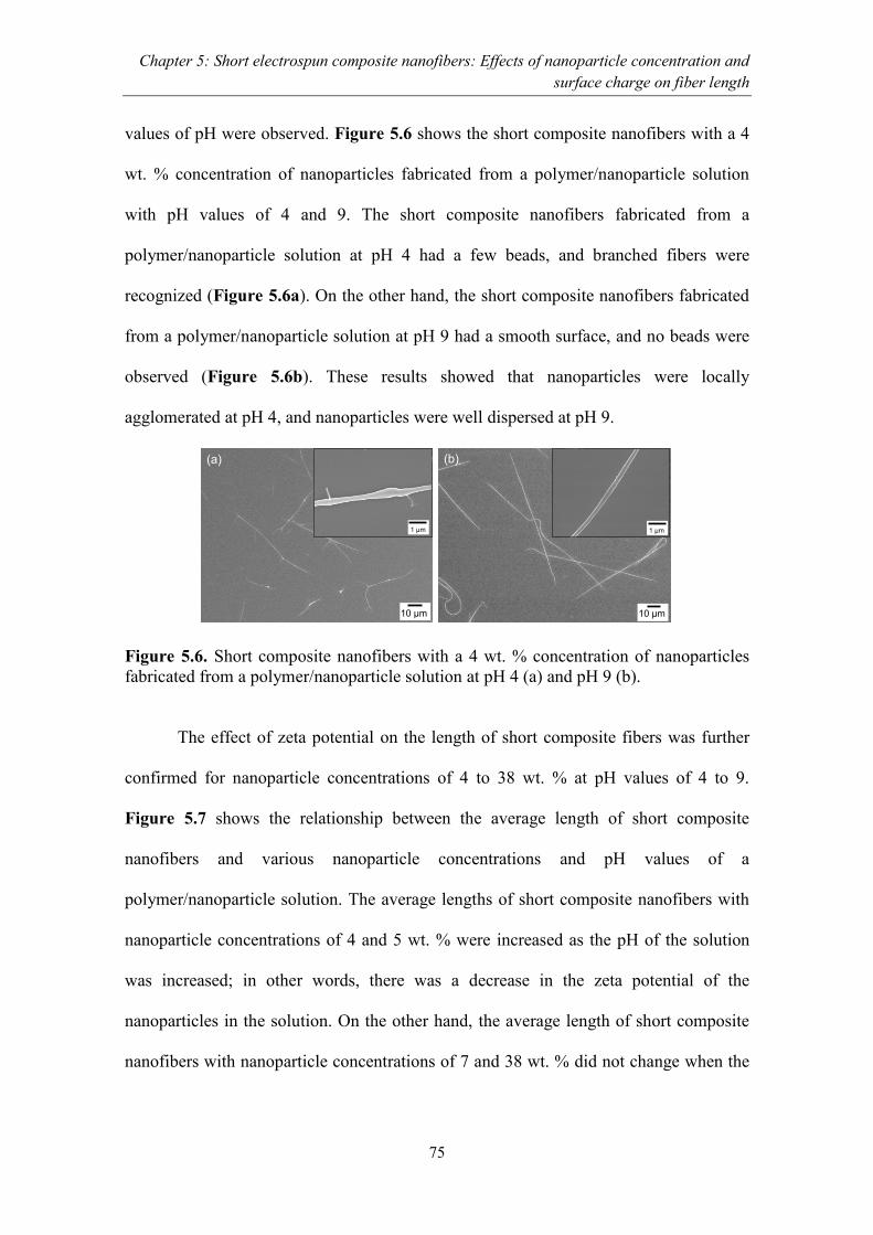
Chapter 5: Short electrospun composite nanofibers: Effects of nanoparticle concentration and
surface charge on fiber length
75
values of pH were observed. Figure 5.6 shows the short composite nanofibers with a 4
wt. % concentration of nanoparticles fabricated from a polymer/nanoparticle solution
with pH values of 4 and 9. The short composite nanofibers fabricated from a
polymer/nanoparticle solution at pH 4 had a few beads, and branched fibers were
recognized (Figure 5.6a). On the other hand, the short composite nanofibers fabricated
from a polymer/nanoparticle solution at pH 9 had a smooth surface, and no beads were
observed (Figure 5.6b). These results showed that nanoparticles were locally
agglomerated at pH 4, and nanoparticles were well dispersed at pH 9.
Figure 5.6. Short composite nanofibers with a 4 wt. % concentration of nanoparticles
fabricated from a polymer/nanoparticle solution at pH 4 (a) and pH 9 (b).
The effect of zeta potential on the length of short composite fibers was further
confirmed for nanoparticle concentrations of 4 to 38 wt. % at pH values of 4 to 9.
Figure 5.7 shows the relationship between the average length of short composite
nanofibers and various nanoparticle concentrations and pH values of a
polymer/nanoparticle solution. The average lengths of short composite nanofibers with
nanoparticle concentrations of 4 and 5 wt. % were increased as the pH of the solution
was increased; in other words, there was a decrease in the zeta potential of the
nanoparticles in the solution. On the other hand, the average length of short composite
nanofibers with nanoparticle concentrations of 7 and 38 wt. % did not change when the
(a)
10 µm
1 µm
(b)
10 µm
1 µm
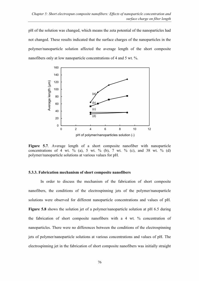
Chapter 5: Short electrospun composite nanofibers: Effects of nanoparticle concentration and
surface charge on fiber length
76
pH of the solution was changed, which means the zeta potential of the nanoparticles had
not changed. These results indicated that the surface charges of the nanoparticles in the
polymer/nanoparticle solution affected the average length of the short composite
nanofibers only at low nanoparticle concentrations of 4 and 5 wt. %.
Figure 5.7. Average length of a short composite nanofiber with nanoparticle
concentrations of 4 wt. % (a), 5 wt. % (b), 7 wt. % (c), and 38 wt. % (d)
polymer/nanoparticle solutions at various values for pH.
5.3.3. Fabrication mechanism of short composite nanofibers
In order to discuss the mechanism of the fabrication of short composite
nanofibers, the conditions of the electrospinning jets of the polymer/nanoparticle
solutions were observed for different nanoparticle concentrations and values of pH.
Figure 5.8 shows the solution jet of a polymer/nanoparticle solution at pH 6.5 during
the fabrication of short composite nanofibers with a 4 wt. % concentration of
nanoparticles. There were no differences between the conditions of the electrospinning
jets of polymer/nanoparticle solutions at various concentrations and values of pH. The
electrospinning jet in the fabrication of short composite nanofibers was initially straight
0
20
40
60
80
100
120
140
160
0 2 4 6 8 10 12
Avera
ge
len
gth
(µ
m)
pH of polymer/nanoparticles solution (-)
(c)
(b)
(d)
(a)

Chapter 5: Short electrospun composite nanofibers: Effects of nanoparticle concentration and
surface charge on fiber length
77
and continuous, and then it was broken and spread-out several millimeters away from
the needle tip with a spread angle of approximately 20o. The electrospinning jet in the
fabrication of short composite nanofibers was different from the electrospinning jet in
the fabrication of continuous nanofibers, which was not spread and spiral at 1 to 2 cm
away from the needle tip [33].
Figure 5.8. Electrospinning jet of a polymer/nanoparticle solution at pH 6.5 during the
fabrication of short composite nanofibers with a 4 wt. % concentration of nanoparticles.
Figure 5.9 shows a short composite nanofiber with a 4 wt. % concentration of
nanoparticles fabricated from a solution at pH 9. Figure 5.9b shows the end portion of a
short composite nanofiber, which corresponds to the rectangle in Figure 5.9a. The
diameter at the end portion of the short composite nanofiber was narrower than the
diameter of the center portion. The narrower diameter at the end portion of the short
composite nanofiber was observed on all the prepared short composite nanofibers. This
indicated that the composite fiber was locally stretched by the electric field generated
from the applied high voltage, and led to a thinning of the diameter of the composite
nanofiber and to a breakaway of the composite nanofiber.
200 µm
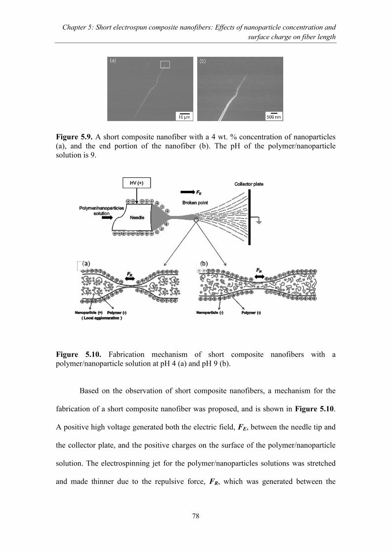
Chapter 5: Short electrospun composite nanofibers: Effects of nanoparticle concentration and
surface charge on fiber length
78
Figure 5.9. A short composite nanofiber with a 4 wt. % concentration of nanoparticles
(a), and the end portion of the nanofiber (b). The pH of the polymer/nanoparticle
solution is 9.
Figure 5.10. Fabrication mechanism of short composite nanofibers with a
polymer/nanoparticle solution at pH 4 (a) and pH 9 (b).
Based on the observation of short composite nanofibers, a mechanism for the
fabrication of a short composite nanofiber was proposed, and is shown in Figure 5.10.
A positive high voltage generated both the electric field, FE, between the needle tip and
the collector plate, and the positive charges on the surface of the polymer/nanoparticle
solution. The electrospinning jet for the polymer/nanoparticles solutions was stretched
and made thinner due to the repulsive force, FR, which was generated between the

Chapter 5: Short electrospun composite nanofibers: Effects of nanoparticle concentration and
surface charge on fiber length
79
positive charges on the surface of the polymer/nanoparticle solutions. At low
concentrations of nanoparticles in a solution at pH 4, the positively charged
nanoparticles were attracted to the negatively charged polymer, and they were locally
aggregated. Thus, the solution was easily broken during stretching, which resulted in a
short length (Figure 5.10a). On the other hand, at a low concentration of nanoparticles
in solutions at pH 9, the polymers were repelled by the negatively charged nanoparticles,
and, thus, the nanoparticles were evenly dispersed in the solution and the composite
nanofiber became longer (Figure 5.10b). The negative charges within the
polymer/nanoparticle solution were attracted to the positive charges generated on the
surface of the polymer/nanoparticle solution and then redistributed to allow the electric
field inside the electrified polymer/nanoparticles solution to be zero. This mechanism
has been proposed by Reneker et al. in the electrospinning of various polymer solutions
[34]. With a high concentration of nanoparticles, either positively or negatively charged
nanoparticles were locally aggregated with the polymer, and then composites nanofibers
were easily cut, which resulted in shorter composite nanofibers. Thus, the surface
charges of the nanoparticles affected the length of the short composite nanofibers only
at low concentrations of nanoparticles.
5.4. Conclusions
Short polymer/nanoparticle composite fibers with concentrations of
nanoparticles as high as 50 wt. % were successfully fabricated via electrospinning using
13 wt. % cellulose acetate polymer under a voltage of 5.5 kV and at a flow rate of 0.1
µL/min. The concentration and the surface charges of nanoparticles affected the length
of short composite nanofibers. The average lengths of short composite nanofibers were
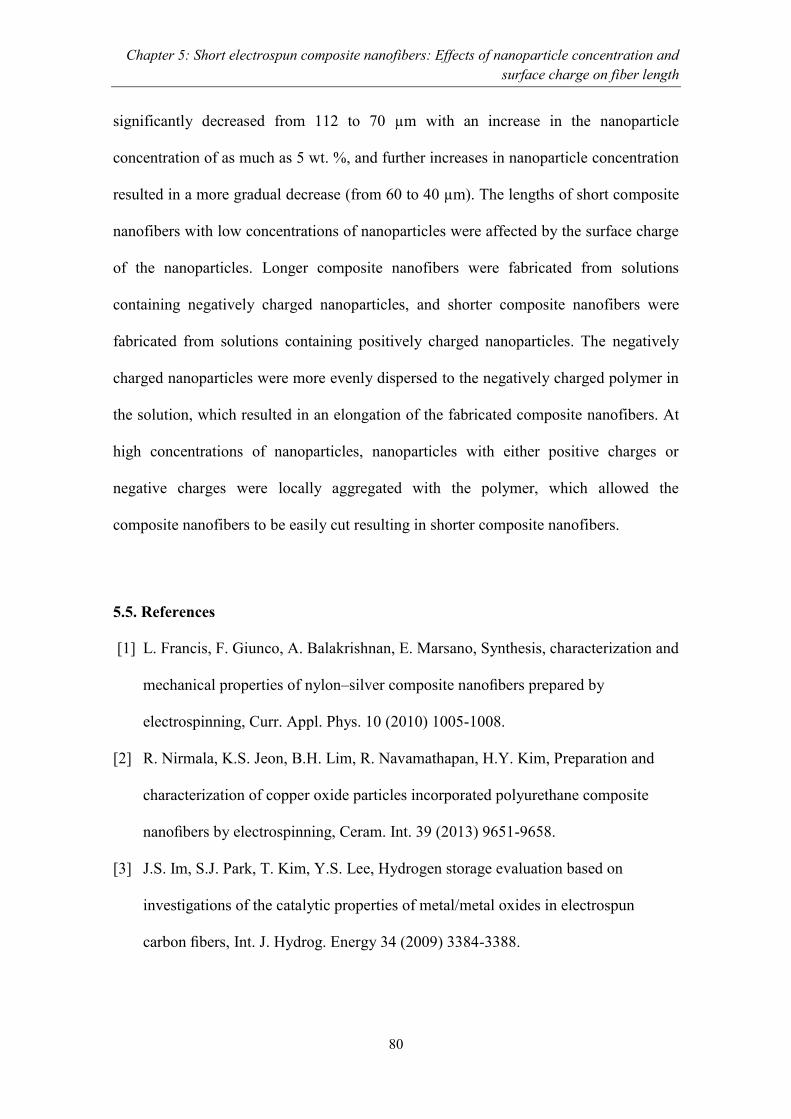
Chapter 5: Short electrospun composite nanofibers: Effects of nanoparticle concentration and
surface charge on fiber length
80
significantly decreased from 112 to 70 µm with an increase in the nanoparticle
concentration of as much as 5 wt. %, and further increases in nanoparticle concentration
resulted in a more gradual decrease (from 60 to 40 µm). The lengths of short composite
nanofibers with low concentrations of nanoparticles were affected by the surface charge
of the nanoparticles. Longer composite nanofibers were fabricated from solutions
containing negatively charged nanoparticles, and shorter composite nanofibers were
fabricated from solutions containing positively charged nanoparticles. The negatively
charged nanoparticles were more evenly dispersed to the negatively charged polymer in
the solution, which resulted in an elongation of the fabricated composite nanofibers. At
high concentrations of nanoparticles, nanoparticles with either positive charges or
negative charges were locally aggregated with the polymer, which allowed the
composite nanofibers to be easily cut resulting in shorter composite nanofibers.
5.5. References
[1] L. Francis, F. Giunco, A. Balakrishnan, E. Marsano, Synthesis, characterization and
mechanical properties of nylon–silver composite nanofibers prepared by
electrospinning, Curr. Appl. Phys. 10 (2010) 1005-1008.
[2] R. Nirmala, K.S. Jeon, B.H. Lim, R. Navamathapan, H.Y. Kim, Preparation and
characterization of copper oxide particles incorporated polyurethane composite
nanofibers by electrospinning, Ceram. Int. 39 (2013) 9651-9658.
[3] J.S. Im, S.J. Park, T. Kim, Y.S. Lee, Hydrogen storage evaluation based on
investigations of the catalytic properties of metal/metal oxides in electrospun
carbon fibers, Int. J. Hydrog. Energy 34 (2009) 3384-3388.

Chapter 5: Short electrospun composite nanofibers: Effects of nanoparticle concentration and
surface charge on fiber length
81
[4] E. Zhao, C. Ma, W. Yang, Y. Xiong, J. Li, J. Sun, Electrospinning La0.8Sr0.2
Co0.2Fe0.8O3-δ tubes impregnated with Ce0.8Gd0.2O1.9 nanoparticles for an
intermediate temperature solid oxide fuel cell cathode, Int. J. Hydrog. Energy 38
(2013) 6821-6829.
[5] S. Anita, B. Brabu, D. J. Triruvadigal, C. Gopalakrishnan, T.S. Natarajan, Optical,
bactericidal and water repellent properties of electrospun nano-composite
membranes of cellulose acetate and ZnO, Carbohydr. Polym. 87 (2012) 1065-1072.
[6] V. Modafferi, G. Panzera, A. Donato, P.L. Antonucci, C. Cannilla, N. Donato, D.
Spadaro, G. Neri, Highly sensitive ammonia resistive sensor based on electrospun
V2O5 fibers, Sens. Actuator B: Chem.163 (2012) 61-68.
[7] A. Mahapatra, B.G. Mishra, G. Hota, Electrospun Fe2O3-Al2O3 nanocomposite
fibers as efficient adsorbent for removal heavy metal ions from the aqueous
solution, J. Hazard. Mater. 258-259 (2013) 116-123.
[8] G. Yu, X. Li, X. Cai, W. Cui, S. Zhou, J. Weng, The photoluminescence
enhancement of electrospun poly(ethylene oxide) fibers with CdS and polyaniline
inoculations, Acta Materialia 56 (2008) 5775-5782.
[9] L. Huang, L. Cheng, H. Yu, J. Zhang, L. Zhou, J. Sun, H. Zhong, X. Li, Y. Tian, Y.
Zheng, T. Yu, C. Li, H. Zhong, W. Liu, L. Zhang, J. Wang, B. Chen,
Electrospinning preparation and optical transition properties of Eu(DBM)3Phen/PS
fluorescent composite fibers, Opt. Commun. 285 (2012) 1476-1480.
[10] H.R. Pant, D.R. Pandeya, K.T. Nam, W. Baek, S.T. Hong, H.Y. Kim,
Photocatalytic and antibacterial properties of a TiO2/nylon-6 electrospun
nanocomposite mat containing silver nanoparticles, J. Hazard. Mater. 189 (2011)
465-471.
Chapter 5: Short electrospun composite nanofibers: Effects of nanoparticle concentration and
surface charge on fiber length
82
[11] R. Liu, H. Ye, X. Xiong, H. Liu, Fabrication of TiO2/ZnO composite nanofibers by
electrospinning and their photocatalytic property, Mater. Chem. Phys. 121 (2010)
432-439.
[12] H.R. Pant, B. Pant, P. Pokharel, H.J. Kim, L.D. Tijing, C.H. Park, D.S. Lee, H.Y.
Kim, C.S. Kim, Photocatalytic TiO2–RGO/nylon-6 spider-wave-like nano-nets via
electrospinning and hydrothermal treatment, J. Membr. Sci. 15 (2013) 225-234.
[13] Y. Horie, T. Watanabe, M. Deguchi, D. Asakura, T. Nomiyama, Enhancement of
carrier mobility by electrospun nanofibers of Nb-doped TiO2 in dye sensitized solar
cells, Electrochim. Acta, 105, (2013) 394-402.
[14] J.S. Lee, Y.I. Lee, H. Song, D.H. Jang, Y.H. Choa, Synthesis and characterization
of TiO2 nanowires with controlled porosity and microstructure using
electrospinning method, Curr. Appl. Phys. 11 (2011) S210-S214.
[15] M. Su, J. Wang, H. Du, P. Yao, Y. Zheng, X. Li, Characterization and humidity
sensitivity of electrospun ZrO2:TiO2 hetero-nanofibers with double jets, Sens.
Actuators B: Chem. 161 (2012) 1038-1045.
[16] L. Zhou, N. Wu, Q. Cao, B. Jing, X. Wang, Q. Wang, H. Kuang, A novel
electrospun PVDF/PMMA gel polymer electrolyte with in situ TiO2 for Li-ion
batteries, Solid State Ionics 249-250 (2013) 93-97.
[17] X. Zhang, S. Xu, G. Han, Fabrication and photocatalytic activity of TiO2
nanofiber membrane, Mater. Lett. 63(2009) 1761-1763.
[18] M. Hamadanian, A. Akbari, V. Jabbari, Electrospun titanium dioxide nanofibers:
fabrication, properties and its application I photo-oxidative degradation of methyl
orange (MO), Fibers Polym. 12 (2011) 880-885.
Chapter 5: Short electrospun composite nanofibers: Effects of nanoparticle concentration and
surface charge on fiber length
83
[19] A. Wagh, et al, A short circulating peptide nanofiber as a carrier for tumoral
delivery, Nanomedicine: NBM 9 (2013) 449-457.
[20] L. Fu, Y. Wu, F. Li, B. Zhang, Synthesis of InNbO4 short nanofiber membrane as
visible-light-driven photocatalyst, Mater. Lett. 109 (2013) 225-228.
[21] S. Jiang, G. Duan, J. Schöbel, S. Agarwal, A. Greiner, Short electrospun polymeric
nanofibers reinforced polyimide nanocomposites, Compos. Sci. Technol. 88 (2013)
57-61.
[22] M.H. Al-Saleh, U. Sundararaj, Review of mechanical properties of carbon
nanofiber/polymer composites, Composites: Part A 42 (2011) 2126-2142.
[23] M. Endo, Y.A. Kim, T. Hayashi, K. Nishimura, T. Matusita, T. Mayashita, M.S.
Dresselhaus, Vapor-grown carbon fiber (VGCFs) basic properties and their battery
applications, Carbon 39 (2001) 1287-1297.
[24] S. Mahalingam, M. Edirisinghe, Forming of polymer nanofibers by a pressurised
gyration process, Macromol. Rapid Commun. 34 (2013) 1134–1139.
[25] L.D. Tijing, A. Amarjargal, Z. Jiang, M.T.G. Ruelo, C.H. Park, H.R. Pant, D.W.
Kim, D.H. Lee, C.S. Kim, Antibacterial tourmaline nanoparticles/polyurethane
hybrid mat decorated with silver nanoparticles prepared by electrospinning and UV
photo reduction, Curr. Appl. Phys. 13 (2013) 205-210.
[26] N.A.M. Barakat, M.F. Abadir, F.A. Sheikh, M.A. Kanjwal, S. J. Park, H.Y. Kim,
Polymeric nanofibers containing solid nanoparticles prepared by electrospinning
and their applications, Chem. Eng. 156 (2010) 487-495.
[27] D.P. Macwan, P.N. Dave, S. Chaturvedi, A review on nano-TiO2 sol–gel type
syntheses and its applications, J. Mater. Sci. 46 (2011) 3669–3686.
Chapter 5: Short electrospun composite nanofibers: Effects of nanoparticle concentration and
surface charge on fiber length
84
[28] A.E. Deniz, A. Celebioglu, F. Kayaci, T. Uyar, Electrospun polymeric nanofibrous
composites containing TiO2 short nanofibers, Mater. Chem. Phys. 129 (2011) 701-
704.
[29] I.W. Fathona, A. Yabuki, One-step fabrication of short electrospun fibers using an
electric spark, J. Mater. Proces. Technol. 213 (2013) 1894-1899.
[30] I.W. Fathona, A. Yabuki, A Simple One-Step Fabrication of Short Polymer
Nanofibers via Electrospinning, J. Mater. Sci. 49 (2014) 3519–3528.
[31] N. Veronovski, P. Andreozzi, C. La Mesa, M.S. Smole, Stable TiO2 dispersions for
nanocoating preparation, Surf. Coat. Tech. 204 (2010) 1445-1451.
[32] H. Matsumoto, Y. Koyama, A. Tanioka, Preparation and characterization of novel
weak amphoteric charged membrane containing cysteine residues, J. Coll. Interface
Sci. 239 (2001) 467–474.
[33] D.H. Reneker, A.L. Yarin, H. Fong, S. Koombhongse, Bending instability of
electrically charged liquid jet of polymer solutions in electrospinning, J Appl. Phys.
87 (2000) 4531-4547.
[34] D.H. Reneker, A.L. Yarin, Electrospinning jets and polymer nanofibers, Polymer
49 (2008) 2387-2425.
85
Chapter 6
Summary
The one-step fabrication method to fabricate short polymer fiber by
electrospinning has been discussed. The effect of electrospinning parameters such as
polymer concentration, applied voltage, and solution flow rate, and nanoparticle
addition have been investigated in order to control the length of short polymer fiber.
Two types of one-step fabrication processes for short polymer fibers by
electrospinning were developed, which is used electric spark as cutting tool and is
controlled electrospinning conditions. The methodology to control the length of short
polymer fibers was developed by altering a needle inner diameter, applied voltage, flow
rate of polymer solution, and added the nanoparticles. These one-step fabrication
processes and methodology in controlling short polymer fiber could be simply
explained in the following:
(i) The one-step fabrication process was combining an electrospinning method and
electric spark generation at once time. Electric spark was used as a cutting tool
of electrospun polymer fiber during electrospinning process. High voltage with a
square wave was applied to two electrodes to generate a periodic electric spark
that could be recognized at 4.1 kV. The following results has been discussed and
explained in Chapter 2:
a. Solution of cellulose acetate and organic solvent was ejected from a syringe
needle and was stretched by the electric field then it cut after passed through
the gap between the tips of two electrodes that generated an electric spark
with frequency of 5 kHz.
Chapter 6: Summary
86
b. The short fibers of average 231 µm were found on the collector plate with a
density of 1-5 fibers per 0.12x0.2 mm2, whereas the fibers that did not flow
through to the electric spark were uncut and remained as continuous fibers
on the collector plate.
c. The theoretical fiber length was calculated at 271 µm when employing a 5
kHz of electric spark, which was in good agreement with the length of the
short fibers obtained in the experiment.
(ii) The simple and one-step process fabrication of short polymer nanofibers has
been successfully developed based on simple electrospinning method. The
length also could be controlled by controlling electrospinning parameters. The
process of this methodology is described in Chapter 3, which could be
summarized as follows:
a. A polymer solution was loaded into a syringe, and was then ejected by the
application of high voltage. The effect of the concentration of the polymer
solution, the applied voltage, and the flow rate of the polymer solution was
investigated for its effect on the length of short nanofibers.
b. The concentration of the cellulose acetate polymer in the solution was
important factor which varied from 13 to 15 wt. %. The length of fibers was
increased by increasing the flow rate of the solution, and it was decreased
with an increase in applied voltage, resulting in controllable length of short
nanofibers at 37 to 670 µm.
c. The edges of the short nanofibers were narrowed by stretching. Observation
of the polymer solution jet that was ejected from the needle tip showed it
passing straight, and then spreading due to lateral perturbations on its surface.
Chapter 6: Summary
87
The breaking of the fibers into short nanofibers occurred because the
repulsive force from the surface charges and the longitudinal force from the
applied voltage surpassed the tensile strength of the polymer solution jet.
(iii) The effect of the needle size on the length of nanofiber was investigated and
describe in Chapter 4, and the following results were obtained: The short
nanofiber average diameter was increased approximately twice, as the needle
inner diameter was increased from 0.16 to 0.26 mm. The short nanofibers
average length was increased with the factors 1.5-1.6, as needle inner diameter
was increased 1.6. The breaking of the fibers into short nanofibers occurred due
to an imbalance between the force of the surface tension of the polymer solution
and the longitudinal force from the applied voltage.
(iv) The effect of nanoparticle concentration and surface charge on short composite
fibers fabrication has been investigated (Chapter 5) resulted in the following
points:
a. Short composite fiber has been fabricated via electrospinning using 13 wt. %
cellulose acetate polymer and TiO2 nanoparticles under a voltage of 5.5 kV
and at a flow rate of 0.1 µL/min. Concentration of nanoparticle in the fiber
could be achieved as high as 50 wt. %.
b. The average lengths of short composite nanofibers were significantly
decreased from 112 to 70 µm with an increase in the nanoparticle
concentration of as much as 5 wt. %, and further increases in nanoparticle
concentration resulted in a more gradual decrease (from 60 to 40 µm).
c. The lengths of short composite nanofibers with low concentrations of
nanoparticles were affected by the surface charge of the nanoparticles.
Chapter 6: Summary
88
Longer composite nanofibers were fabricated from solutions containing
negatively charged nanoparticles, and shorter composite nanofibers were
fabricated from solutions containing positively charged nanoparticles. The
negatively charged nanoparticles were more evenly dispersed to the
negatively charged polymer in the solution, which resulted in an elongation
of the fabricated composite nanofibers.
d. At high concentrations of nanoparticles, nanoparticles with either positive
charges or negative charges were locally aggregated with the polymer, which
allowed the composite nanofibers to be easily cut resulting in shorter
composite nanofibers.