fabrication of special icf targets a depolymerizable .../67531/metadc626410/...fabrication of...
TRANSCRIPT

UCRG JC-121115 PREPRINT
Fabrication of Special ICF Targets using a Depolymerizable Mandrel Technique
S. A. Letts E. M. Fearon L. M. Allison R. Cook
This paper was prepared for submittal to the 42nd National Symposium of the American Vacuum Society
Minneapolisf MN October 16-20,1995
October 5 1995
Thisisa preprintof a paper intended forpublication ina journalorpr&eedings. Since changes may be made before publicatioa, this preprint is made available with the understanding that it will not be cited or reproduced without the permission of the author.

This document wasprepared as anaammt of work spansored by an agency of the UNtd *tes Government. Neither the United States Government n a the University of California nor any of their employees, makes any warranty, express or impiied, or assumes any legal liability or responsibility for the accuracy, completeness, or usefulness of any information, apparahls, product, or disdosed, or represents that its use would not infringe privately em= Referenoe herein to any spedfic commercial prod-, proas, or service by trade name, &&emark, mdacturer, or otherwise, does not necessarily constitute or imply its endorsement, recommendatian, or favoring by the United States Government or the University of California. The views and opinions d authors expressed herein do not “ecessarily state or reflect those of the United States Govemnmt or the University of Wontia, and shall not be used for advertising c x ~ e n d O ~ t p l l q o e %
Portions of this document may be fllegfble lo t)e!c&onic image products Images are pmduced from the best available Originat docmnmt.
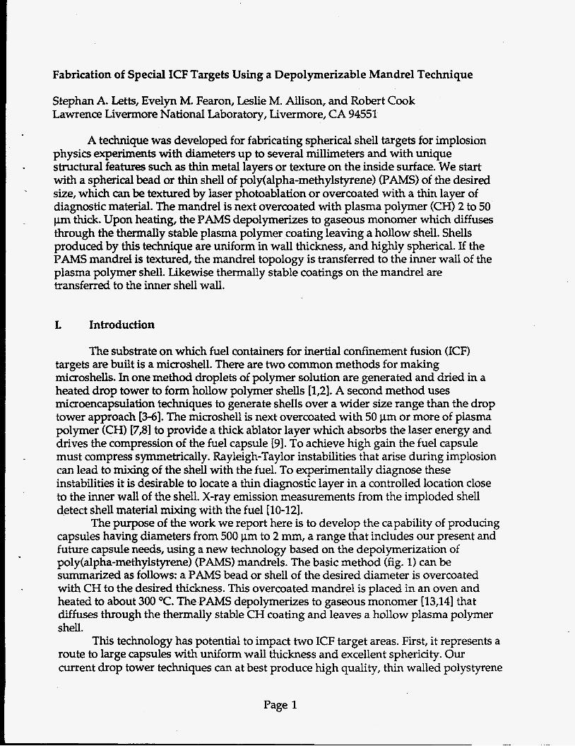
Fabrication of Special ICF Targets Using a Depolymerizable Mandrel Technique
Stephan A. Letts, Evelyn M. Fearon, Leslie M. Allison, and Robert Cook Lawrence Livermore National Laboratory, Livermore, CA 94551
A technique was developed for fabricating spherical shell targets for implosion physics experiments with diameters up to several millimeters and with unique structural features such as thin metal layers or texture on the inside surface. We start with a spherical bead or thin shell of polflalpha-methylstyrene) (PAMS) of the desired size, which can be textured by laser photoablation or overcoated with a thin layer of diagnostic material. The mandrel is next overcoated with plasma polymer (CH) 2 to 50 pm thick. Upon heating, the PAMS depolymerizes to gaseous monomer which diffuses through the thermally stable plasma polymer coating leaving a hollow shell. Shells produced by this technique are uniform in wall thickness, and highly spherical. If the PAMS mandrel is textured, the mandrel topology is transferred to the inner wall of the plasma polymer shell. Likewise thermally stable coatings on the mandrel are transferred to the inner shell wall.
L Introduction
The substrate on which fuel containers for inertial confinement fusion (ICF) targets are built is a microshell. There are two common methods for making microshells. In one method droplets of polymer solution are generated and dried in a heated drop tower to form hollow polymer shells [1,2]. A second method uses microencapsulation techniques to generate shells over a wider size range than the drop tower approach [3-6]. The microshell is next overcoated with 50 pm or more of plasma polymer (CH) [7,8] to provide a thick ablator layer which absorbs the laser energy and drives the compression of the fuel capsule [9]. To achieve high gain the fuel capsule must compress symmetrically. Rayleigh-Taylor instabilities that arise during implosion can lead to mixing of the shell with the fuel. To experimentally diagnose these instabilities it is desirable to locate a thin diagnostic layer in a controlled location close to the inner wall of the shell. X-ray emission measurements from the imploded shell detect shell material mixing with the fuel [lo-121.
The purpose of the work we report here is to develop the capability of producing capsules having diameters from 500 pm to 2 mm, a range that includes our present and future capsule needs, using a new technology based on the depolymerization of poly(alpha-methylstyrene) (PAMS) mandrels. The basic method (fig. 1) can be summarized as follows: a PAMS bead or shell of the desired diameter is overcoated with CH to the desired thickness. This overcoated mandrel is placed in an oven and heated to about 300 "C. The PAMS depolymerizes to gaseous monomer [13,14] that diffuses through the thermally stable CH coating and leaves a hollow plasma polymer shell.
This technology has potential to impact two ICF target areas. First, it represents a route to large capsules with uniform wall thickness and excellent sphericity. Our current drop tower techniques can at best produce high quality, thin walled polystyrene
Page 1
shells with diameters of about 500 pm. Microencapsulation, while able to produce large shells, does not always result in uniform wall thickness and vacuole defects are often present in the shell wall 161. With the depolymerizing mandrel technique, we form the layer that becomes the shell by vapor deposition; wall uniformity is consequently good. Second, this method offers the possibility of producing capsules with unique diagnostic or structural features. Previous reports on this subject have discussed primarily the use of solid bead PAMS mandrels [15,16]. In this report we will concentrate on the use of hollow shell mandrels. We will show that thin uniform shells can be prepared by this method. In addition we report the incorporation of unique features in the target shells such as inner texture in the form of laser photoablated pits or thin metal diagnostic layers.
11. Shell Mandrel Preparation
Bead mandrels tested previously have some advantages-they are relatively easy to fabricate and can be made with excellent sphericity and surface finish [15,16]. However, distortion occurring during CH overcoating and during pyrolysis led us to investigate shell mandrels. Shells can be made by microencapsulation techniques in the 500 pm to 2 mm diameter range 13-61. Thick walled shells prepared this way usually are not uniform in wall thickness and may contain numerous vacuole bubbles in the wall that form during drying. However, in the depolymerizing mandrel process, since the mandrel is pyrolyzed, the requirements are only that the shell be smooth and spherical. Shell mandrels have three advantages over solid beads: there is much less PAMS to remove, forces exerted on the CH coating during pyrolysis are lower because of the low mass of the PAMS layer, and pressure generated by gas evolution during pyrolysis is lower because of the large void volume.
using techniques of microencapsulation. The material chosen for the shells was monodisperse 96 k Mw PAMS. PAMS shells from 500 p.m to 2 mm diameter are prepared by a two stage emulsion process. The first step is to prepare a water-in-oil emulsion by pouring water into a 5 weight percent PAMS solution (toluene, 1,2 dichloroethane, ethyl-ethylketone) formulated to match the density of water. The solution is broken up into small droplets with agitation. This emulsion is next poured into a stirred dilute poly(viny1 alcohol) (PVA) solution to produce a water-in-oil-in- water emulsion. Solvent is removed from the oil phase by an in-liquid drying procedure involving heating for several hours in suspension.
A rotary atomic force microscope (AFM) was used to characterize shells for sphericity 1171. In a rotary AFM, the sample is rotated on an air bearing to scan the shell under the AFM tip. This provides an accurate technique for detecting deviations from sphericity as well as measurements of surface roughness. Fig. 2 shows a rotary AFM trace for a PAMS shell mandrel. The deviation from sphericity of this 450 pm diameter mandrel is about 200 nm.
Shell mandrels used in this study were prepared at General Atomics, San Diego,
. I
III. Pyrolyzed Shell Characterization
Page 2

The final step in processing is to pyrolyze the coated mandrel at 300 "C for 500 minutes as described in earlier work [15,16]. Shells made by the depolymerizing mandrel process were characterized for thickness, surface smoothness, uniformity and sphericity using a number of techniques. General assessment of shell quality was performed with an optical microscope to detect large deformations, cracks, and particles. Two perpendicular diameter measurements were made to assess Sphericity. Mass was determined which, combined with diameter and density, enabled us to calculate the wall thickness of the shell. If the shell appeared to be of good quality, other characterization techniques including scanning electron microscopy (SEM), interferometry, AFM and rotary AFM were used to examine in greater detail the quality of the shell.
One of our objectives was to investigate the range of CH thickness that could be achieved by the depolymerizing mandrel process. In earlier experiments we deposited 15 to 50 p of CH overcoating on the PAMS mandrels [15,16]. Recently we have tested thinner overcoatings to determine the feasibility of producing thin shells. A series of coatings 15,5 and 2 pm thick were deposited on 450 to 900 vm diameter shell mandrels. The mandrels were then decomposed by pyrolysis.
prepared as thin as 2 pm wall thickness. Interferometric characterization (Fig. 3) shows a pyrolyzed shell that is uniform in wall thickness and is spherical. Analysis of the interferometer image shows that this shell has wall nonuniformity of only 1.3% in its poorest orientation. For 900 p diameter shell mandrels, 2 p CH wall thickness resulted in breakage or deformation during pyrolysis. However, at 5 pm wall thickness the shells survived.
We found for 450 pm diameter mandrels, shells with good sphericity could be
IV. Textured Inner Surface
To study Rayleigh-Taylor instabilities a technique has been developed using laser photoablation with an argon-fluoride excimer laser to produce shaped pits on the outer surface of the target [17,181. In this technique, an argon-fluoride laser (193 nm wavelength) is focused to a small spot to produce gaussian pits on the surface. For these experiments, beam fluence was calculated to be 77 millijoules/cm2 with a pulse width of 20 ns. A depth of 1 pn was achieved with 13 laser pulses. Combining photoablation with the decomposable mandrel technique, we have investigated the possibility of producing texture on the inner surface of the shell.
Pits were photoablated on PAMS shell mandrels with diameters from 650 to 950 pn and a wall thickness of approximately 8 p. One hundred pits were laid down in a regular pattern on one hemisphere of the mandrel. The pits were mapped at four stages: as ablated, after adding 35 and 70 pm of CH, and after pyrolyzing the PAMS out of a subset of the 3 5 p thick overcoated shells.
of the surface. The sphere was oriented on the rotary AFM vacuum chuck so that the pits would pass under the AFM tip as it traced the equator. By taking a trace and then stepping the sphere in 5 p increments, we were able to profile a 125 pm wide band around the equator. From these data we reconstructed the surface topography of the pits and obtained dimensions of the most completely imaged pits. An example of a
We measured the pit depths and widths by using the rotary AFM to map a band
Page 3

scanned band map from one of the shells after thermal decomposition of the PAMS is shown in Fig. 4.
the sphere. Because the band profiled by the rotary AFM is only 125 p wide, most of the pits were partially imaged. We measured only the pits that had a minimum of 70% of the surface visible. On each shell we were able to measure at least three pits. The average diameter and depth dimensions of the pits were: 119 pm by 0.63 pm on the PAMS mandrel; 129 pm wide by 0.79 pm deep with 35 p.m of plasma polymer; 136 pm wide by 0.73 p deep with 70 pm of plasma polymer; and 124 p by 0.67 pm deep after
The apparent 15% increase in pit diameter for the overcoated shells before pyrolysis of the PAMS is probably due both to poor statistics and to the uncertainty in identifying the pit boundary in the overcoated shells. The data clearly show that the contour of the pits does not change appreciably even with the addition of 70 pm of CH coating. The coating conforms to the surface topography. The actual contour of the inside texture was not measured. We believe the exterior AFM scans represent closely the inside texture since the coating is highly conformal. To fill in the pits would require a self leveling coating technique such as solvent casting or melting of a thermoplastic overcoating layer where surface tension would drive the liquid layer to smooth over the pits.
We did not attempt to measure identical pits because of the difficulty of orienting
pyrolysis.
V, Diagnostic Layer on Inner Surface
To diagnose mix caused by Rayleigh-Taylor instability at the shell-fuel interface, targets have been seeded with a number of elements [10,11,19]. In these experiments, the desired element was covalently incorporated in the polystyrene that is subsequently blown into a hollow shell in a drop tower. This doped shell becomes the inner layer of the fuel capsule. This approach imposes two restrictions: first, a chemical synthesis route must exist for the element to be incorporated; second, the diagnostic element can only be uniformly distributed throughout the thickness (usually 3 p) of the polystyrene shell.
Using the depolymerizing mandrel approach, we have investigated the possibility of producing high quality shells for diagnostic targets by sputtering the diagnostic element. Sputter deposition has two advantages: a wide range of elements can be incorporated, and the diagnostic can be located precisely at a desired location within the target. The two restrictions associated with the use of the depolymerizing mandrel approach are: the surface of the deposited layer must be smooth, and the layer must be permeable to the gas evolved from the decomposing mandrel. For our application, the thickness of the diagnostic layer can be very thin. Previous targets incorporating titanium in the 3 pm polystyrene shell at the 0.1 atomic percent level have the equivalent of 3 nm of pure titanium. For this thickness we will show that the sputtered layer is both smooth and permeable to the decomposed mandrel.
10 nm thick, on PAMS shell mandrels. The metal layers were next overcoated with CH 5,15 and 30 pn thick, and then the inner PAMS mandrel was removed by pyrolysis.
To test the feasibility of incorporating metal layers, we deposited titanium, 5 and
Page 4

The layers were finally characterized using x-ray fluorescence (XRF) to confirm the metal thickness.
We found from optical microscopy, SEM, and AFM that 5 and 10 nm thick titanium layers did not increase the surface roughness. Using the same pyrolysis canditions resulted in complete removal of the mandrel which indicated that the titanium layer did not impede gas diffusion during pyrolysis of the mandrel. After fracturing, SEM examination showed the inner surface to be smooth and particle free. Interferometry on the shells showed them to be uniform and spherical. XRF before and after pyrolysis showed the titanium content was unchanged.
VI, Conclusions
Using a depolymerizing PAMS shell mandrel process we have made uniform, smooth, CH shells that meet the quality requirements of the ICF program. Shells were made with diameters from 0.4 to 2 mm with sphericity better than 1%. Wall nonuniformity was shown by interferometry to be less than 2%. Surface finish was measured by AFM and was found to be on the order of 5 nm RMS for 15 pm thick shells. In addition we have shown that two new types of diagnostic targets can be prepared using this technique. First, texture was transferred to the inner wall by photoablating pits on the surface and overcoating with plasma polymer. Second, 5 to 10 nm thick layers of titanium were located on the inner surface of the fuel capsde by sputter coating on the mandrel which was subsequently removed by pyrolysis.
Acknowledgments
The authors wish to thank Ed Lindsey, Craig Moore, Andrea Pad, Rand McEachern, Bob Turner, and Charlotte King for providing analytical support for this project; Steve Buckley and Mike Saculla for help in developing the mandrel processing methods and thermal analysis; Bill Wilcox for performing the laser photoablation; and Ricke Behymer for providing the titanium coatings. We gratefully acknowledge the efforts of Don Czechowicz and Fred Elsner from General Atomics who developed the microencapsulation process and produced the PAMS shell mandrels used in this study.
References
[I] [2] [3] [4]
[5]
[6]
[7]
A.K. Bumham, J.Z. Grens, E.M. Lilley, J. Vac. Sa. Technol. A 5(6), 3417 (1987). R Cook, Mat. Res. Soc Symp. Roc., 372,101 (1995). U. Kubo, H. Tsubakihara, J. Vac. Sci. Technol. A 4,1134 (1986). M. Takagi, T. Norimatsu, T. Yamanaka, and S. Nakai, J. Vac. Sci. Technol. A 9(3), 820 (1991). M. Takagi, T. Norimatsu, Y. Izawa, and S. Nakai, Mat. Res. Soc. Symp. Proc., 372, 199 (1995). T. Boone, L. Cheung, D. Nelson, D. Soane, G. Wilemski, and R. Cook, Res. Soc. Symp. Proc., 372,193 (1995). S.A. Letts, D.W. Myers, L.A. Witt, J. Vac Sa. Technol. 19,739 (1981).
Page 5
G.W. Collins, S.A. Letts, E.M. Fearon, R.L. McEachern, T.P. Bernat, Phys. Rev. Lett 73,708 (1994). J.D. Lindl, E.M. Campbell, Physics Today, 45(9), 32 (1992). C.J. Keane, G.W. Pollak, RC. Cook, T.R Dittrich, B.A. Hammel, O.L. Landen, S.H. Langer, W.K. Levedahl, D.H. Munro, H.A. Scott, and G.B. Zimmerman, J. Quant. Spectrosc. Radiant Transfer, 54,207 (1995)- O.L. Landen, C.J. Keane, B.A. Hanunel, M.D. Cable, J. Colvin, R Cook, T.R. Ditbich, S.W. Haan, SIP. Hatchett, RG. Hay, J.D. Kilkenny, RA. Lerche, W.K. Levedahi, R McEachem, T.J. Murphy, M.B. Nelson, L. Suter, and RJ. Wallace, J. Quant. Speetrocs. Radiant Transfer, 54,245, (1995). T.R Dettrich, B.A. Hammel, RE. Tumer, R McEachern, C.J. Keane, S.W. Haan, and LJ. Suter, Phys. Rev. Lett. 73,2324 (1994). H.H.G. Jellin&, H. Kachi, J. Poly. Sci. C 23,97 (1968). S.L. Malhotra, C. Baillet, L. Minh, L.P. Blanchard, J. Macromolec. Sei-Chem. A 12(1), 129 (1978). S.A. Letts, E.M. Fearon, S.R. Buckley, M.D. Sadla, L.M. Allison, and R.C. Cook, Mat. Res. Sot. Symp. Proc., 372,125 (1995). S.A. Letts, E.M. Fearon, S.R Buckley, M.D. Sadla, L.M. Allison, and RC. Cook, Fus. Tec, (Submitted). RL McEachern, C.E. Moore, RJ. Wallace, J. Va. Sci. T&oL A 13(3), 983 (1995). RJ. Wallace, RL. McEachern, and W.W. Wilcox, ICF Q. Rep. 94,79 (1994), UCRL-
R Cook, G.E. Overturf, R McEachern, and S.R Buddey, J. Vac Sci. Technol. A 12(4), 1275 (1994).
LR-I05821-9&3.
7hp work was performed under the auspices of the US. Department of Energy by Lawrence l-iierinore NatOnal khratoty under contract No. W-7405-Eng-48.
Page 6

Figure Captions
Figure 1. Hollow shells can be produced by (a) starting with a poly(alpha- methylstyrene) shell, then overcoating with a thermally more stable plasma polymer. The coated shell is pyrolyzed at 300 "C for 10 hours leaving a spherical hollow shell. Imperfections in the mandrel such as bubbles or wall thickness nonuniformity are eliminated by pyrolysis of the mandrel. The surface of the mandrel can be (b) textured by photoablation, or (c) coated with a thin metal layer.
Figure 2 Rotary AFM traces around the circumference of a PAMS shell mandrel show that spherical deformation is about 200 nm for a 500 pm diameter or 0.04%.
Figure 3. An interferometric image of a pyrolyzed CH shell shows that it is uniform and spherical. The shell diameter is 394 pn with a wall thickness of 5.1 p. Nonconcentriaty was measured to be 1.3%.
Figure 4. A contour map scanned on the rotary AFM from one of the shells after thermal decomposition of the PAMS is shown. The pits are 125 pm wide and 0.7 pm deep. The pits appear unchanged in shape from the original on the mandrel.
Page 7

Fig. 1 Special shells from depolymerizable mandrel process
Microencapsulated PAMS - Pyrolyze ___) 300°C
Titanium coated PAMS shell

Figure 2. Sphere map of p-enc PAMS shell
0 4 5 90 135 180 225 270 315 360
degrees

Fig 3. interferogram thin baked shell

Figure 4. Band map of baked CH coated photoablated PAMS shell
h
E S Y
5 P 2
Width (pm) lb- 600