facon-plc communication protocol - fatek uk · ascii code→ stx h l h l 0〜500 ascii code h l etx...
TRANSCRIPT

FACON-PLC
Communication
Protocol
FATEK AUTOMATION CORP.
3/16/2001
Ver. 1.1

FACON PLC Communication Protocol Contents
1: The definition of Master and Slave device ............................................................................................1
2: The communication message format of FACON PLC.....................................................................1
3: The communication error code of FACON PLC .................................................................................2
4: The function description of communication command .................................................................3
4.1 The accessible elements and its designation ....................................................... 3
4.2 The description of communication command ........................................................ 4
Command 40:Read the brief system status of PLC ....................................................... 6
Command 41:Control the PLC RUN/STOP.................................................................... 7
Command 42:Control single discrete element............................................................... 8
Command 43:Read multiple ENABLE/DISABLE status of discrete elements ................... 9
Command 44:Read multiple status of consecutive discrete elements ............................. 10
Command 45:Write multiple status of consecutive discrete elements ............................. 11
Command 46:Read multiple consecutive registers ........................................................ 12
Command 47:Write to multiple consecutive registers .................................................... 13
Command 48:Mixed read the arbitrary discrete and register data .................................. 14
Command 49:Mixed write the arbitrary discrete and registers........................................ 15
Command 4E:Loop back test....................................................................................... 16
Command 4F:Read program ....................................................................................... 17
Command 50:Write program........................................................................................ 18
Command 53:Read the detail system status of PLC...................................................... 19

The Communication Protocol of FACON PLC
The FA CON PL C comm un i ca t i on p r o toco l i s a pp l i ca b le f o r a l l commu n ica t i on po r t s o f FAC ON PL C tha t wo rk unde r t he s ta nda rd mod e . Any pe r i ph e ra l s t ha t wan t t o comm un ica t e w i t h FA CO N PL C, bes ide s h a rdware i n te r fa ce , commun ica t i on pa ra me te rs m us t ac co rdan ce w i th FA CO N PL C a l so t he f o rma t o f t he message mus t f o l l ow th i s commun ica t i on p ro toco l .
1. The def in i t ion of Master and Slave device
FAC ON P LC a c ts as a s lave wh i l e c ommun i ca t i n g w i t h pe r i phe ra l dev i ce t ha t a lwa ys ac t s a s mas te r when c ommun i ca t e w i t h FA CO N PL C. A l l t he pe r i phe ra l de v i c es ac t i ve l y s end the mes sage t o t he FA CON PL C an d FA C ON PL C w i l l pas s i v e l y re sponse th e me ssag e a f t e r rece i ve t he mes sage f ro m mas te r.
Command message
Mas te r (Pe r i phe ra l dev i ces )
S lave (FACON PLC)
Response
2.The Message Format of FACON Communicat ion Protocol
The re a re 6 f i e l d s i n t he FAC ON PL C me ssage i nc l ud ing c ommand (m as te r ) and respo nse ( s l ave ) message .
Send ing d i rec t i on F i r s t send Las t send
↓ ↓ � � � � � �
F ie ld name→
S ta r t code
S lave s ta t i on
No .
Command code Da ta
Checksum
End code
ASCI I code→ STX H L H L 0〜 500 ASCI I code H L ETX
L R C s u m
�Sta r t code (STX): The AS CI I code o f STX i s 02 H i n h exade c ima l f o rma t . The s t a r t cha rac t e r i s STX bo th f o r comman d and res ponse me ssa ge . Wh i le r ece i v i ng , c an d i sc r im ina te t he message s ta r t by check ing the STX code .
�The s t a t i on No . o f s l a v e: The s ta t i on n umber c ons i s t s o f tw o he xadec im a l cha r ac te r s . The re i s on l y one ma s te r s ta t i on and 255 s lave s ta t i o ns can b e ex i s ted fo r FAC ON PL C commun i ca t i on n e two r k . Eve r y s lave s t a t i on ha s a un iq ue s ta t i on n umber f r om 1〜 F EH ( I f t he s ta t i on N o . i s 0 me ans the m essa ge i s f o r a l l s l a ve s ta t i o n ) .
1

When the ma s te r wa n t t o send a command m essa ge to a ce r ta in s lav e i t w i l l pu t t he s ta t i on n o . o f t h e acco r dan t s l av e i n t o t h e s l a ve s t a t i on f i e ld o f t he command me ssage i n o rd e r t o add ress t ha t s l av e . The s lave w i l l pu t i t ’ s ow n s ta t i o n no . i n to t he s lav e s ta t i on f i e l d o f t he re sponse mess age th en se nd back to mas te r.
R e m a r k: T h e s t a t i o n n o . o f FA C O N P L C a r e a l l s e t t o 1 b e f o r e s h i p m e n t . T h e s t a t i o n n o . c a n n o t b e s e t t h r u t h e FA C O N c o m m u n i c a t i o n p r o t o c o l , i t c a n o n l y b e c h a n g e d b y u s i n g t h e F P - 0 7 o r P r o g r a m m i n g s o f t w a r e s u c h a s P R O - L A D D E R o r W i n P r o l a d d e r.
�Comm and c ode : The command code cons i s t s o f two hexad ec ima l ch a rac t e rs . I t i s t h e ac t i on wh i ch t he mas te r wan ts s l av e t o execu t e . Fo r examp le , t o read o r w r i t e t he s ta t us o f d i sc re t e , f o r c i n g , r u n , s t op… The command co de o f t he respon se mess a ge i s i den t i ca l t o t he command message .
�Dat a i n f o rma t i o n :T he da ta i n fo rma t i on co n ta in s 0 (no da ta )〜 500 AS CI I ch a rac te rs . Th e da ta i n t h i s f i e l d i s t o ass ign t he a dd r ess o r va l ue f o r r ead i ng o r w r i t i ng . The f i r s t d a ta o f t he response m essa ge i s t h e e r ro r code . I n no rm a l con d i t i on (no e r r o r happene d ) t he e r ro r code mu s t be ‘ 0 ’ ( 3 0 H) and th en fo l l o w the re spond i ng s ta tus o r va lu e i n t he response mes sage . Wh e n e r ro r hap pened , i t s va l ue w i l l be o t he r t h an ‘ 0 ’ ( 30H) and the da ta i n fo rma t i on w i l l be absen t .
�Che cks um : Ch ecksum i s t he s ummat i o n o f t he hexad ec im a l va lue o f A S CI I cod e i n t h e p rev iou s �〜� f i e l ds an d the su m w i l l o n l y t a kes by te v a lue ( tw o h exade c ima l va lue 00〜 FF) t ha t i s s o ca l l e d “L RC (Lon g i t ud ina l Redundan cy Ch eck ) ” me t hod . Th i s mes sage w i l l be che cked w i th t he sa me w ay a t t he rec e i v i ng s ide whe n the message i s re ce i ved . Wh en the t wo ch eck va lu es a re t he sa me , i t means th e da ta t r ans fe r red co r re c t l y. I f t he tw o c heck va lues a re d i f f e ren t , t he r e a re some e r ro r happened . The ca l cu la t i o n o f LR C me th od i s t o ad d a l l t h e hexa dec i ma l v a l ue (8 b i t s l e ng th ) o f A SCI I cod e and i gno re t he ca r r y t o keep the ch eck v a lue a t 8 b i t s l eng th .
�En d code (ET X): The hexade c ima l c ode o f ET X code o f A SCI I i s 03H . T he ETX c ode fo r bo th t he command o r re spons e me ssage i s t he same . When the rece i v i ng s i de re ce i ve s t he ETX code , i t means th a t t he da ta t r ansm iss ion o f t h i s mes sage i s ended an d can s ta r t t o p rocess t he command .
3.The communicat ion error code of FACON PLC
I f t he mess age h as e r ro r s i n c ommand code , add r e ss o r ove r ra nge o f va lue o r ha rdw are p rob lem w i l l ca use the s la ve dev i ce ca n no t p ro ces s the c omm and comes f rom mas te r dev i ce . I f t he re i s e r r o r happened , s lave dev i ce w i l l r espon d the me ssage t o mas t e r de v i ce . No ma t t e r wha t co mmand code o r da ta t he mas t e r dev i ce sends , t h e f o rma t o f r e spond i ng mess age i s a l l t he same . I nc lud in g t h e requ i red s ta r t cod e ( STX ) , end code ( ETX) and c hecks um v a lue , t he com mand c ode and s ta t i on N o . w i l l be sen t back t o m as t e r dev i ce . Th e s l ave dev i ce w i l l j udg e wh a t k ind o f t he e r ro r and re spond th e e r ro r code to mas te r dev i ce acco rd ing l y.
2

● Fo l l ow ing tab le i s t he response e r ro r code o f FACON PLC:
E r ro r code (Hex ) Desc r i p t i on
0 No e r ro r
2 I l l ega l va lue (ex . Dec ima l f o rma t con ta ins hexadec ima l number )
3 Wr i t e p roh ib i t ed (PLC equ ipped w i th ROM PACK)
4 I l l ega l command fo rma t ( I nc ludes i l l ega l command code ) o r command can no t execu te
5 Can no t r un (Ladde r Checksum e r ro r when run PLC)
6 Can no t r un (PLC ID no t i den t i ca l w i t h Ladde r ID when run PLC)
7 Can no t r un (Syn tax check e r ro r when run PLC)
9 Can no t r un (One o r more i ns t ruc t i ons i n l adde r p rog ram i s no t suppo r ted by t h i s PLC)
A I l l ega l r e fe rence add ress
4.The funct ion descr ipt ion of communicat ion command
In t h i s sec t i on w i l l i l l u s t ra te t he f o rma t o f t h e command and res pon se mess ages fo r a l l command cod es tha t FAC ON suppo r ted . (O n ly t he s ucces s fu l r es ponse w i l l b e i l l us t r a ted , f o r t he e r ro r r esponse p lease re fe r sec t i on 3 )
4 .1 The access ib le e lements and i ts des ignat ion
The ma in f un c t i o n o f PL C commun ica t i on i s t o r ead and wr i t e t he s ta tu s o r va lue i ns id e P LC e lemen t s . C once rn ing t he d i sc re te and reg i s te r wh i ch a re a va i l ab le f o r r ead and wr i t e a re des i gna ted and re fe renced by f o l l ow ing tab le:
Elements
Symbol
Name D isc re te add ress
(5 cha rac te rs )
16 b i t s reg i s te r add ress
(6 cha rac te rs )
32 b i t s reg i s te r add ress (7 cha rac te rs )
X I npu t d i sc re te X0000〜 X9999 WX0000〜 WX9984 DWX0000〜 DWX9968
Y Ou tpu t re l ay Y0000〜 Y9999 WY0000〜 WY9984 DWY0000〜 DWY9968
M In te rna l r e l ay M0000〜 M9999 WM0000〜 WM9984 DWM0000〜 DWM9968
S S tep re lay S0000〜 S9999 WS0000〜 WS9984 DWS0000〜 DWS9968
T T imer d i sc re te T0000〜 T9999 WT0000〜 WT9984 DWT0000〜 DWT9968
Discrete
C Coun te r d i sc re te C0000〜 C9999 WC0000〜 WC9984 DWC0000〜 DWC9968
TMR T imer reg i s te r − RT0000〜 RT9999 DRT0000〜 DRT9998
CTR Coun te r reg i s te r − RC0000〜 RC9999 DRC0000〜 DRC9998
HR Da ta reg i s te r − R00000〜 R65535 DR00000〜 DR65534
Data register
DR Da ta reg i s te r − D00000〜 D65535 DD00000〜 DD65534
3

● The d i sc re t e s ta tu s (X, Y, M, S)c an comb ine 16 o r 32 con secu t i ve s ta tus as t he 16 -b i t o r 32 -b i t r eg i s te r, s uch as t he a bo ve tab le W X△△△△ o r D WX△△△△ , bu t △△△△ s hou ld be t he mu l t i p l e o f 8 .
● I t nee ds 5 cha rac t e rs wh en as s ign t he d i sc re t e a d d ress and 6 cha rac te rs w hen a ss ig n t h e 1 6 -b i t r eg i s te r add ress and 7 cha rac te rs t o ass ign t he 32 -b i t r eg i s te r add ress .
● The add res s range o f e l emen ts i n abo ve tab le i s t he l a rg es t f o r a l l mode l s o f FAC ON PL C. Th e use rs sh ou ld n o t i c e t he app l i cab le add res s o f ea ch e leme n t f o r PLC i n ha nd . (E x . Fo r FB E- PLC , t he range fo r X、 Y add r ess i s 000 0〜 0255 ; f o r S i s 000 0〜 0 999 ) I f exce ed the ra nge o f va l i d add ress , PLC w i l l r ep l y e r ro r code “A” ( i l l ega l add ress ) , and w i l l no t execu te t ha t command .
4 .2 The descr ip t ion o f communicat ion command
● The desc r i p t i on o f commun ica t i on command:
Command code (Hex )
Func t i on desc r i p t i on Da ta s i ze can be
p rocessed w i th one command
Remark
40 Read the br ie f sys tem s ta tus o f PLC − 41 Con t ro l t he RUN/STOP o f PLC − 42 Wr i te s ing le d isc re te s ta tus 1 po in t
43
Read mul t ip le ENABLE/DISABLE s ta tus o f d isc re te e lements
1〜 256 po in t s
44 Read mul t ip le s ta tus o f consecut ive d isc re te e lements
1〜 256 po in t s
45 Wr i te mu l t ip le s ta tus o f consecut ive d isc re te e lements
1〜 256 po in t s
46 Read mul t ip le consecut ive reg is te rs da ta 1〜 64 Words 47 Wr i te mu l t ip le consecut ive reg is te rs da ta 1〜 64 Words
48
Mixed read o f a rb i t ra ry d isc re te and reg is te r s ta tus
1〜 64 po in t s o r Words
49 Mixed wr i te o f a rb i t ra ry d isc re te and reg is te r s ta tus
1〜 32 po in t s o r Words
4E Loop back tes t 0〜 256 cha rac te rs 4F Read program 64 Words 50 Wr i te p rogram 64 Words 53 Read the de ta i l sys tem s ta tus o f PLC −
4

1: The mes sage o f d i sc re te s ta tus i s r ep re sen ted b y o ne cha rac te r ( 1 means ON , 0 mea ns OFF) and the da t a o f 16 -b i t r eg i s te r us es 4 cha r ac te rs t o rep rese n t t he va lue o f one WORD(0000H〜 FFFFH)
2: The da t a o f 32 -b i t r eg i s te r i s DW( t wo con s ecu t i ve Word s ) , i t has t o use 8 cha rac t e rs t o rep resen t i t s da ta . I f t he e lemen t i s 32 -b i t r eg i s te r, t he e l emen t has t o be t r ea ted a s 2 W. Fo r examp le , t he comma nd cod e 46 o r 47 can p r ocess 64 16 -b i t e l emen t s and on l y ca n p rocess 32 32 -b i t e l emen ts .
3: I n t he comma nd code 4 8 and 49 , t he da t a l eng t h i s t he t o ta l o f d i sc re te and reg i s t e r e l emen t and can no t ex c eed 64 W(co mmand 48 ) a nd 32 W(comm and 49 ) . As i nc re ase one po in t , i t s t o ta l r eg i s te rs w i l l dec rea se one word , v i ce ve rs us . Beca use th e da ta l eng th o f 32 -b i t e lemen t i s 2 wo rds , t he app l i c ab le re g i s t e r o r d i sc re te w i l l be redu ce d by 2 when i nc reas e one 32 -b i t e l em en t . Fo r examp l e , t he da t a l eng th o f com mand 48 i s 1〜 64 W. I f i t r ead 2 0 32 -b i t e l emen t s , i t s mes sage w i l l o ccup y 40 words a nd rema in 2 4W a va i l ab le f o r d i sc re te o r 16 -b i t r eg i s te r. I n t h i s ex am p le , co mmand code can read 44 e leme n ts (20 32 -b i t e l emen ts and 24d i sc re te o r 16 -b i t e l emen ts ) i n one commun ica t i on .
4: The ope ra t i on ( rea d and wr i t e ) o f co nsec u t i v e d i sc re te o r reg i s te r ca n be ea s i l y a ss ig ned by t he s ta r t i ng r e fe renc e number an d i t s s i ze , no e numera t i o n i s r equ i red . T he ope ra t i ng e lemen ts can on l y be ing one o f d i sc re te o r r eg i s te r and can no t be ope ra ted m ixed .
5: The com mand o f a rb i t r a r y ope ra t i ng on ob jec t s c an read o r w r i t e s eve ra l d i sc re te an d reg i s te r a t w i l l . As t he i r number i s no t con secu t i v e , yo u ha ve to des i gna te t he i r numb er hence can a l l ow ope ra t i ng on d i sc re te and reg i s te r r andomly.
6: The Re ad a nd Wr i t e p rog ram ope ra t i on re t r i eve a l l t he p rog ram a rea o f PLC o r w r i t e t he PLC p ro g ram to PL C. Th e max imum da t a t r ans fe r r i ng i n one comm un i ca t i o n i s 64 wo rds so tha t i t w i l l t akes many t imes o f commun ica t i on t o comp le te t he ope ra t i on .
5

6
● Command code 40 (Read the brief system status of PLC)
Format
MASTER Command
S T X
0 1 4 0 C 7 E T X
H L H L H L
Station No.
Comm
and code
PLC response
S T X 0 1 4 0
STATUS 1
STATUS 2
STATUS 3
Check sum
E T X
Station No.
Comm
and code
Check sum
H L H L Error code
H L H L H L H L
H
L STATUS 1: B7 B6 B5 B4 B3 B2 B1 B0
STATUS 2: (LADDER program capacity)
00H ,RESERVE FFH ,FB 8K Step program 53H ,FBE 8K Step program 54H ,FBE 13K Step program 55H ,FBN 8K Step program 56H ,FBN 13K Step program
STATUS 3: 0 (Reserve for future)
B0:Run/Stop 0 – Stop, 1- Run B1:Battery status 0 – Normal, 1 – Low energy B2:Ladder checksum status
0 – Normal , 1- Error B3:ROM PACK usage 0- Not use, 1- use B4:WDT status 0 – OK , 1 - Error B5: ID status 0 – Not set, 1- set B6:Emergency stop status
0 – OK , 1 – Emergency stop B7:0 (Reserve for future)
Ex.
If the PLC is equipped with ROM PACK and ID is set in both PLC and ROM PACK and PLC status is “RUN” under normal condition, the system status of PLC which MASTER read will be as following: (B5,B3, and B0 are 1 and the other are all 0 that the STATUS is 29H) .
MASTER Command
S T X
0 1 4 0 C 7 E T X
02H 30H 31H 34H 30H 43H 37H 03H
PLC response
S T X
0 1 4 0 0 2 9 0 0 0 0 2 2 E T X
02H 30H 31H 34H 30H 30H 32H 39H 30H 30H 30H 30H 30H 32H 32H

7
● Command code 41 (Control the RUN/STOP of PLC)
Format
MASTER Command
S T X
0 1 4 1 C 7 E T X
H L H L
Control code H L
Station No.
Comm
and code
PLC response
S T X 0 1 4 1
Check sum
E T X
Station No.
Comm
and code
H L H L
Error code
H L
0:STOP Control code 1:RUN
Ex. Control the PLC to “RUN”
MASTER Command
S T X
0 1 4 1 1 F 9 E T X
02H 30H 31H 34H 31H 31H 46H 39H 03H
PLC response
S T X
0 1 4 1 0 F 8 E T X
02H 30H 31H 34H 31H 30H 46H 38H 03H

8
● Command code 42 (Control single discrete element)
Format This command can control the designated discrete to do ENABLE, DISABLE, SET, RESET four operations.
MASTER Command
S T X
0 1 4 2 Discrete No.
Check sum
E T X
H L H L
Running code
H L Station No.
Comm
and code
PLC response
S T X
0 1 4 2
Check sum
E T X
H L H L
Error code H L
1:Disable 2:Enable 3:Set
Running code
4:Reset
Ex. The following communication format is the example to DISABLE the discrete X16.
MASTER Command
S T X
0 1 4 2 1 X 0 0 1 6 1 9 E T X
02H 30H 31H 34H 32H 31H 58H 30H 30H 31H 36H 31H 39H 03H
PLC response
S T X
0 1 4 2 0 F 9 E T X
02H 30H 31H 34H 32H 30H 46H 39H 03H

9
● Command code 43 (Read multiple ENABLE/DISABLE status of discrete elements)
Format Use this command to read the ENABLE/DISABLE status of consecutive discrete elements.
MASTER Command
S T X
0 1 4 3
Number N
Star No.
Check sum
E T X
H L H L H L
Station No.
Comm
and code
PLC response
S T X
0 1 4 3 ••••
Check sum
E T X
Station No.
Comm
and code H L H L
Error code Status 0 Status 1
Status N
H L
Number N: The range of two-digit Hex value can be 1≤N≤256 (When N=00H it equals to256)
Ex.
Among the 7 consecutive discrete elements of Y10~Y16, if the DISABLE/ENABLE status of Y10, Y12, Y16 are DISABLE, and the others are all ENABLE, the PLC status of this command reading is as
MASTER Command
S T X
0 1 4 3 0 7 Y 0 0 1 0 4 B E T X
02H 30H 31H 34H 33H 30H 37H 59H 30H 30H 31H 30H 34H 42H 03H
PLC response
S T X
0 1 4 3 0 1 0 1 0 0 0 1 4 D E T X
02H 30H 31H 34H 33H 30H 31H 30H 31H 30H 30H 30H 31H 34H 44H 03H

10
● Command code 44 (Read multiple status of consecutive discrete elements)
Format
MASTER Command
S T X
0 1 4 4
Number
N Start No.
Check sum
E T X
H L H L H L
Station No.
Comm
and code
PLC response
S T X
0 1 4 4 ••••
Check sum
E T X
Station No.
Comm
and code H L H L
Error code Status 0 Status 1
Status N
H L
Number N: The range of two-digit Hex value can be 1≤N≤256 (When N=00H, is equals to 256)
Ex.
If the status of X50, X52, X55 are all 0 and X51, X53, X54 are all 1, following is the status of reading the consecutive 6 inputs (X50〜X55)
MASTER Command
S T X
0 1 4 4 0 6 X 0 0 5 0 4 E E T X
02H 30H 31H 34H 34H 30H 36H 58H 30H 30H 35H 30H 34H 44H 03H
PLC response
S T X
0 1 4 4 0 0 1 0 1 1 0 1 E E T X
02H 30H 31H 34H 34H 30H 30H 31H 30H 31H 31H 30H 31H 44H 03H X55 Status
X54 Status No error X53 Status
X52 Status X51 Status X50 Status
N=6

11
● Command code 45 (Write multiple status of consecutive discrete elements)
Format
MASTER Command
S T X
0 1 4 5
Number
N Start No. ••••
Check sum
E T X
H L H L
Status 0 Status 1
Status N
H L
Station No.
Comm
and code
PLC response
S T X
0 1 4 5
Check sum
E T X
Station No.
Comm
and code H L H L
Error code
H L
Number N: The range of two-digit Hex value can be 1≤N≤256 (When N=00H it equals to256)
Ex.
Write the status to consecutive 4 outputs (Y0〜Y3) , Y0 and Y3 are 1, Y1 and Y2 are 0.
Y0 Status Y1 Status Y2 Status Y3 Status
MASTER Command
S T X
0 1 4 5 0 4 Y 0 0 0 0 1 0 0 1 0 B E T X
02H 30H 31H 34H 35H 30H 34H 59H 30H 30H 30H 30H 31H 30H 30H 31H 30H 42H 03H
PLC response
S T X
0 1 4 5 0 F C E T X
02H 30H 31H 34H 35H 30H 46H 43H 03H
12
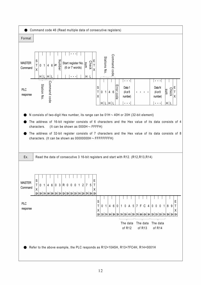
● Command code 46 (Read multiple data of consecutive registers)
Format
•••
MASTER Command
S T X
0 1 4 6
Number
N Start register No. (6 or 7 words)
Check sum
E T X
H L H L ••• H L
Stations No.
Comm
and code
••• •••
PLC response
S T X
0 1 4 6 Data 1 (4 or 8
number) ••••
Data N (4 or 8
number)
Check sum
E T X
Station No.
Comm
and code H L H L
Error code
••• ••• H L
● N consists of two-digit Hex number, its range can be 01H〜40H or 20H (32-bit element)
● The address of 16-bit register consists of 6 characters and the Hex value of its data consists of 4 characters. (It can be shown as 0000H〜FFFFH)
● The address of 32-bit register consists of 7 characters and the Hex value of its data consists of 8 characters. (It can be shown as 00000000H〜FFFFFFFFH)
Ex. Read the data of consecutive 3 16-bit registers and start with R12. (R12,R13,R14)
MASTER Command
S T X
0 1 4 6 0 3 R 0 0 0 1 2 7 5 E T X
02H 30H 31H 34H 36H 30H 33H 52H 30H 30H 30H 31H 32H 37H 35H 03H
PLC response
S T X
0 1 4 6 0 1 0 A 5 7 F C 4 0 0 0 1 8 9 E T X
02H 30H 31H 34H 36H 30H 31H 30H 41H 35H 37H 46H 43H 34H 30H 30H 30H 31H 38H 39H 03H
The data
of R12
The data of R13
The data of R14
● Refer to the above example, the PLC responds as R12=10A5H, R13=7FC4H, R14=0001H

13
● Command code 47 (Write to multiple consecutive registers)
Format
••• ••• •••
MASTER Command
S T X
0 1 4 7
Number
N Start register No. (6 or 7 words)
Data 1 (4 or 8
numbers) •••
Data N (4 or 8
numbers) Check sum
E T X
H L H L ••• ••• ••• H L
Station No.
Comm
and code
PLC response
S T X
0 1 4 7
Check sum
E T X
Station No.
Comm
and code H L H L
Error code
H L
● N consists of two-digit Hex number, its range can be 01H〜40H or 20H (32-bit element)
● The address of 16-bit register consists of 6 characters and the Hex value of its data consists of 4 characters. (It can be shown as 0000H〜FFFFH)
● The address of 32-bit register consists of 7 characters and the Hex value of its data consists of 8 characters. (It can be shown as 00000000H〜FFFFFFFFH)
Ex.
Write AAAAH to the 16-bit register WY8 and 5555H to WY24. This can use the multiple write register command because WY8 and WY24 are consecutive registers.
Start element numbers
WY8 Data WY24 Data
MASTER Command
S T X
0 1 4 7 0 2 W Y 0 0 0 8 A A A A 5 5 5 5 8 0 E T X
02H 30H 31H 34H 37H 30H 32H 57H 59H 30H 30H 30H 38H 41H 41H 41H 41H 35H 35H 35H 35H 38H 30H 03H
PLC response
S T X
0 1 4 7 0 F F E T X
02H 30H 31H 34H 37H 30H 46H 45H 03H

14
● Command code 48(Mixed read the arbitrary discrete and register data)
Format ••• •••
MASTER Command
S T X
0 1 4 8
Number N
Element No.1 (5, 6 or 7 words) •••••• Element No.N
(5, 6 or 7 words)
Check sum
E T X
H L H L ••• ••• H L
Station No.
Comm
and code �
PLC response
S T X
0 1 4 8
Station No.
Comm
and code
H L H L
Error code
••• •••
Element No.1 data (1, 4 or 8 numbers)
•••••• Element No.N data (1, 4 or 8 numbers)
Check sum
E T X
�
••• ••• H L
● N consists of two-digit Hex number; it means the total numbers of elements. Its range can be 01H〜40H.(Refer to the item 3)
● If the element is discrete, its address consists of 5 characters and status response consists of one character (1 or 0)
● If the element is 16-bit register, its address consists of 6 characters and data response consists of 4-character Hex value.
● If the element is 32-bit register, its address consists of 7 characters and data response consists of 8-character Hex value.
Ex. Read the status of R1,Y9 and DWM0( i.e. M31〜M0)
Element 1 Element 2 Element 3
MASTER Command
S T X
0 1 4 8 0 3 R 0 0 0 0 1 Y 0 0 0 9 D W M 0 0 0 0 3 F E T X
02H 30H 31H 34H 38H 30H 33H 52H 30H 30H 30H 30H 31H 41H 41H 41H 41H 41H 44H 57H 4DH 30H 30H 30H 30H 33H 46H 03H �
PLC response
The status of element 2
S T X
0 1 4 8
02H 30H 31H 34H 37H Data of element 1 Data of element 3
0 5 C 3 4 1 0 0 3 5 4 7 B A C 5 E T X
30H 35H 43H 33H 34H 31H 30H 30H 33H 35H 34H 37H 42H 41H 43H 35H 03H ● In the above example, R1=5C34H and Y9 status is 1(〝ON〞),DWM0=3547BAH
�

15
● Command code 49(Mixed write the arbitrary discrete and registers)
Format ••• ••• •••
MASTER Command
S T X
0 1 4 9
Number N
Element No.1 (5, 6 or 7 words)
Element No.1 data (1, 4 or 8 words)
••••••••••• Element No.N (5, 6 or 7 words)
H L H L ••• ••• •••
•••
Element No.N data (1, 4 or 8 words)
Check sum
E T X
••• H L �
PLC response
S T X
0 1 4 9
Check sum
E T X
H L H L
Error code
H L
● N consists of two-digit Hex number; it means the total elements to write. Its range can be 01H〜20H.(Refer to the item 3)
● If the element is discrete, its address consists of 5 characters and status response consists of one character (0 or 1)
● If the element is 16-bit register, its address consists of 6 characters and data response consists of 4-digit Hex value.
● If the element is 32-bit register, its address consists of 7 characters and data response consists of 8-digit Hex value.
Ex. Set the status of Y0 at 1, Y1 to 0, 16-bit register WM8 to 5555H, 32-bit register DR2 to FFH.
The status of element 1 The status of element 2 Element 1 Element 2 Element 3 Data of element 3
MASTER Command
S T X
0 1 4 9 0 4 Y 0 0 0 0 1 Y 0 0 0 1 0 W M 0 0 0 8 5 5 5 5
02H 30H 31H 34H 39H 30H 34H 59H 30H 30H 30H 30H 31H 59H 30H 30H 30H 31H 44H 57H 4DH 30H 30H 30H 38H 35H 35H 35H 35H
Element 4 Data of element 4
D R 0 0 0 0 2 0 0 0 0 0 0 F F 3 C E T X
44H 52H 30H 33H 30H 30H 32H 30H 30H 30H 30H 30H 30H 46H 46H 33H 43H 03H �
PLC response
S T X
0 1 4 9 0 0 0 E T X
02H 30H 31H 34H 39H 30H 30H 30H 03H
Station No.
Comm
and code
�
�

16
● Command code 4E(Loop back test)
Format
This command makes slave PLC respond al l test data back to Master. It is only for testing the communication condition between Master and PLC and it will not influence the PLC operation.
MASTER Command
S T X
0 1 4 E Testing data X
Check sum
E T X
Station No.
Comm
and code
H L H L H L
PLC response
S T X
0 1 4 6 Testing data X
Check sum
E T X
Station No.
Comm
and code H L H L H L
These two data is the same
Ex.
Use this command to send the data〝ABCDEFG〞 from Master to PLC to test weather the PLC respond normally.
MASTER Command
S T X
0 1 4 E A B C D E F G B 8 E T X
02H 30H 31H 34H 45H 41H 42H 43H 44H 45H 46H 47H 42H 38H 03H
PLC response
S T X
0 1 4 E A B C D E F G B 8 E T X
02H 30H 31H 34H 45H 41H 42H 43H 44H 45H 46H 47H 42H 38H 03H
17
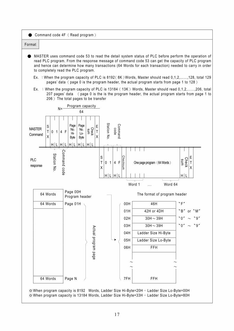
● Command code 4F(Read program)
Format
● MASTER uses command code 53 to read the detail system status of PLC before perform the operation of read PLC program. From the response message of command code 53 can get the capacity of PLC program and hence can determine how many transactions (64 Words for each transaction) needed to carry in order to completely read the PLC program.
Ex. :When the program capacity of PLC is 8192(8K)Words, Master should read 0,1,2,……,128, total 129 pages’ data(page 0 is the program header, the actual program starts from page 1 to 128)
Ex. :When the program capacity of PLC is 13184(13K)Words, Master should read 0,1,2,……,206, total 207 pages’ data (page 0 is the is the program header, the actual program starts from page 1 to 206)The total pages to be transfer
MASTER Command
S T X
0 1 4 F Page No. Hi-
Byte
Page No. Lo- Byte
Check sum
E T X
Station No.
Comm
and code
H L H L H L H L H L
PLC response
S T X
0 1 4 F One page program(64 Words)
Check sum
E T X
Station No.
Comm
and code H L H L
Checksum
H L
Word 1 …. Word 64
64 Words Page 00H Program header The format of program header
64 Words Page 01H 00H 46H 〝F〞
01H 42H or 4DH 〝B〞or〝M〞
02H 30H〜39H 〝0〞〜〝9〞
03H 30H〜39H 〝0〞〜〝9〞
04H Ladder Size Hi-Byte
05H Ladder Size Lo-Byte
06H FFH
〜 〜 〜 〜
64 Words Page N 7FH FFH
※When program capacity is 8192 Words, Ladder Size Hi-Byte=20H,Ladder Size Lo-Byte=00H ※ When program capacity is 13184 Words, Ladder Size Hi-Byte=33H,Ladder Size Lo-Byte=80H
Program capacity N=
64
Actual program page

18
● Command code 50(Write program)
Format
● Master can use this command code to write program to PLC, which were retrieved by previous command code 4F.
If the capacity of writing program is 8192 (8K) Words, Master should transfer 129 pages data to the PLC (page 0 is the program header, the actual program starts from page 1 to 128).
If the saved program capacity is 13184 (13K) Words, Master should transfer 206 pages data to the PLC (page 0 is the program header, the actual program starts from page 1 to 206).
MASTER Command
S T X
0 1 5 0 P No. Hi-
Byte
P No. Lo- Byte
One page program(64 Words)
Checksum
E T X
02H 30H 31H 35H 30H H L H L H L 03H
PLC response
S T X
0 1 5 0
Checksum
E T X
Word 1 …. Word 64
02H 30H 31H 35H 30H
Error code
H L 03H
64 Words Page 00H Program header The format of program header
64 Words Page 01H 00H 46H 〝F〞
01H 42H or 4DH 〝B〞or〝M〞
02H 30H〜39H 〝0〞〜〝9〞
03H 30H〜39H 〝0〞〜〝9〞
04H Ladder Size Hi-Byte
05H Ladder Size Lo-Byte
06H FFH
〜 〜 〜 〜
64 Words Page N 7FH FFH
※When program capacity is 8192 Words, Ladder Size Hi-Byte=20H, Ladder Size Lo-Byte=00H ※When program capacity is 13184 Words, Ladder Size Hi-Byte=33H, Ladder Size Lo-Byte=80H
Program capacity N=
64
Actual program page
Station No.
Comm
and code

19
● Command code 53(Read the detail system status of PLC)
Format
MASTER Command
S T X
0 1 5 3 C B E T X
Station No.
H L H L H L
Comm
and code
PLC response
S T X
0 1 5 3 STATUS 1
STATUS 2
STATUS 3
STATUS 4
STATUS 5
STATUS 6
•••••••• STATUS
64
Check sum
E T X
Station No.
Comm
and code
Checksum
H L H L
Checksum
H L H L H L H L H L H L H L H L
B0:RUN/STOP B1:Battery Low/Normal B2:Ladder checksum error/Normal B3:Use ROM PACK/Not use B4:WDT Time out/Normal B5: ID setting/Not set ID STATUS 15 M Relay Hi-Byte B6:Emergency stop/Normal STATUS 16 M Relay Lo-Byte
STATUS 1
B7: (reserve for future use) STATUS 17 S Relay Hi-Byte Types of Main unit STATUS 18 S Relay Lo-Byte 00H:MA/MU STATUS 19 L Relay Hi-Byte 01H:MC
FB series STATUS 20 L Relay Lo-Byte
STATUS 2
Other values: reserve STATUS 21 R Register Hi-Byte Total I/O points of main unit STATUS 22 R Register Lo-Byte 01H:20 points STATUS 23 D Register Hi-Byte 02H:28 points STATUS 24 D Register Lo-Byte 03H:40 points STATUS 25 Timer Hi-byte
STATUS 3
˙ ˙ STATUS 26 Timer Lo-byte
OS Version of PLC STATUS 27 Counter Hi-Byte 30H:V3.0 STATUS 28 Counter Lo-Byte 31H:V3.1 STATUS 29
STATUS 4 ˙ ˙
STATUS 5 Ladder Size Hi-Byte STATUS 6 Ladder Size Lo-Byte
˙
˙
˙
˙ ˙
˙ STATUS 7 Discrete input Hi-Byte ˙ ˙ STATUS 8 Discrete input Lo-Byte STATUS 9 Discrete output Hi-Byte
˙ ˙
STATUS 10 Discrete output Lo-Byte STATUS 64
˙ ˙
STATUS 11 Analog input Hi-Byte STATUS 12 Analog input Lo-Byte STATUS 13 Analog output Hi-Byte STATUS 14 Analog output Lo-Byte
〜 〜 〜 〜

20
● Command code 53(Read the detail system status of PLC)
Ex.
If the PLC model is FBE-28MC, OS version is 3.10, program capacity is 13K words, without ROM PACK, and ID setting, all the status are normal and in RUN model, then the result of reading the system status is as following:
Ladder size
=13184 DI=256 MASTER Command
S T X
0 1 5 3 C B E T X
02H 30H 31H 35H 33H 43H 42H 03H
Station No.
Comm
and code
STATUS
1
FBE -MC
STATUS
2
28Pt. 之CPU
STATUS
3
OS V3.1
STATUS
4 STATUS
5 STATUS
6 STATUS
7 STATUS
8
�
PLC response
S T X
0 1 5 3 0 2 1 0 1 0 2 3 1 3 3 8 0 0 1 0 0
Station No.
Comm
and code
Checksum
02H 30H 31H 35H 33H 30H 32H 31H 30H 31H 30H 32H 33H 31H 33H 33H 38H 30H 30H 31H 30H 30H
DO=256 AI=64 AO=64
M Relay = 2002
S Relay = 1000
L Relay = 0
R Register = 8072
STATUS
9 STATUS
10 STATUS
11 STATUS
12 STATUS
13 STATUS
14 STATUS
15 STATUS
16 STATUS
17 STATUS
18 STATUS
19 STATUS
20 STATUS
21 STATUS
22 � �
0 1 0 0 0 0 6 4 0 0 6 4 0 7 D 2 0 3 E 8 0 0 0 0 1 F 8 8
30H 31H 30H 30H 30H 30H 36H 34H 30H 30H 36H 34H 30H 37H 44H 32H 30H 33H 45H 38H 30H 30H 30H 30H 31H 46H 38H 38H
D Register = 3072 Timer=256 Counter=256 Reserve
STATUS
23 STATUS
24 STATUS
25 STATUS
26 STATUS
27 STATUS
28 STATUS
29 STATUS
30
�
0 C 0 0 0 1 0 0 0 1 0 0 0 0 0 0 •••• 0 0 0 0
Check sum
E T X
30H 43H 30H 30H 30H 31H 30H 30H 30H 31H 30H 30H 30H 30H 30H 30H 30H 30H 30H 30H 03H